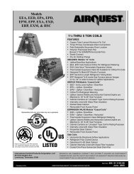
ENA4X Aluminum Uncased N-coil Upflow/Downflow R-410A ...
ENA4X Aluminum Uncased N-coil Upflow/Downflow R-410A ...
ENA4X Aluminum Uncased N-coil Upflow/Downflow R-410A ...

You also want an ePaper? Increase the reach of your titles
YUMPU automatically turns print PDFs into web optimized ePapers that Google loves.
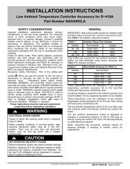
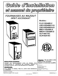
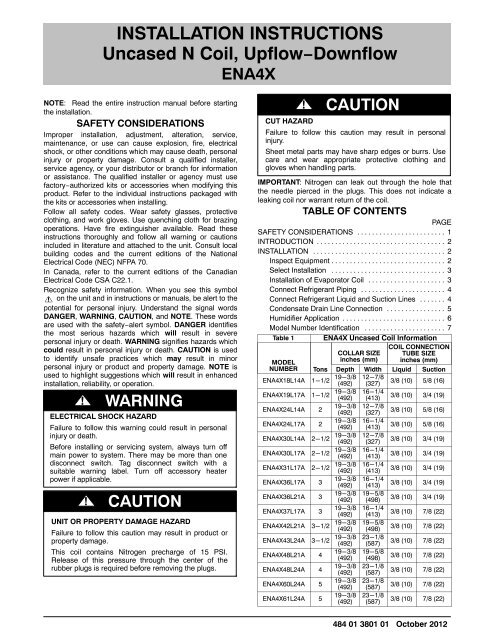
INSTALLATION INSTRUCTIONS<br />
<strong>Uncased</strong> N Coil, <strong>Upflow</strong>−<strong>Downflow</strong><br />
<strong>ENA4X</strong><br />
NOTE: Read the entire instruction manual before starting<br />
the installation.<br />
SAFETY CONSIDERATIONS<br />
Improper installation, adjustment, alteration, service,<br />
maintenance, or use can cause explosion, fire, electrical<br />
shock, or other conditions which may cause death, personal<br />
injury or property damage. Consult a qualified installer,<br />
service agency, or your distributor or branch for information<br />
or assistance. The qualified installer or agency must use<br />
factory−authorized kits or accessories when modifying this<br />
product. Refer to the individual instructions packaged with<br />
the kits or accessories when installing.<br />
Follow all safety codes. Wear safety glasses, protective<br />
clothing, and work gloves. Use quenching cloth for brazing<br />
operations. Have fire extinguisher available. Read these<br />
instructions thoroughly and follow all warning or cautions<br />
included in literature and attached to the unit. Consult local<br />
building codes and the current editions of the National<br />
Electrical Code (NEC) NFPA 70.<br />
In Canada, refer to the current editions of the Canadian<br />
Electrical Code CSA C22.1.<br />
Recognize safety information. When you see this symbol<br />
on the unit and in instructions or manuals, be alert to the<br />
potential for personal injury. Understand the signal words<br />
DANGER, WARNING, CAUTION, and NOTE. These words<br />
are used with the safety−alert symbol. DANGER identifies<br />
the most serious hazards which will result in severe<br />
personal injury or death. WARNING signifies hazards which<br />
could result in personal injury or death. CAUTION is used<br />
to identify unsafe practices which may result in minor<br />
personal injury or product and property damage. NOTE is<br />
used to highlight suggestions which will result in enhanced<br />
installation, reliability, or operation.<br />
! WARNING<br />
ELECTRICAL SHOCK HAZARD<br />
Failure to follow this warning could result in personal<br />
injury or death.<br />
Before installing or servicing system, always turn off<br />
main power to system. There may be more than one<br />
disconnect switch. Tag disconnect switch with a<br />
suitable warning label. Turn off accessory heater<br />
power if applicable.<br />
!<br />
CAUTION<br />
UNIT OR PROPERTY DAMAGE HAZARD<br />
Failure to follow this caution may result in product or<br />
property damage.<br />
This <strong>coil</strong> contains Nitrogen precharge of 15 PSI.<br />
Release of this pressure through the center of the<br />
rubber plugs is required before removing the plugs.<br />
!<br />
CAUTION<br />
CUT HAZARD<br />
Failure to follow this caution may result in personal<br />
injury.<br />
Sheet metal parts may have sharp edges or burrs. Use<br />
care and wear appropriate protective clothing and<br />
gloves when handling parts.<br />
IMPORTANT: Nitrogen can leak out through the hole that<br />
the needle pierced in the plugs. This does not indicate a<br />
leaking <strong>coil</strong> nor warrant return of the <strong>coil</strong>.<br />
TABLE OF CONTENTS<br />
PAGE<br />
SAFETY CONSIDERATIONS ........................ 1<br />
INTRODUCTION ................................... 2<br />
INSTALLATION .................................... 2<br />
Inspect Equipment ............................... 2<br />
Select Installation ............................... 3<br />
Installation of Evaporator Coil ..................... 3<br />
Connect Refrigerant Piping ....................... 4<br />
Connect Refrigerant Liquid and Suction Lines ....... 4<br />
Condensate Drain Line Connection ................ 5<br />
Humidifier Application ............................ 6<br />
Model Number Identification ...................... 7<br />
Table 1 <strong>ENA4X</strong> <strong>Uncased</strong> Coil Information<br />
COIL CONNECTION<br />
MODEL<br />
COLLAR SIZE<br />
inches (mm)<br />
TUBE SIZE<br />
inches (mm)<br />
NUMBER Tons Depth Width Liquid Suction<br />
<strong>ENA4X</strong>18L14A 1-1/2 19-3/8<br />
(492)<br />
12-7/8<br />
(327)<br />
3/8 (10) 5/8 (16)<br />
<strong>ENA4X</strong>19L17A 1-1/2 19-3/8<br />
(492)<br />
16-1/4<br />
(413)<br />
3/8 (10) 3/4 (19)<br />
<strong>ENA4X</strong>24L14A 2<br />
19-3/8<br />
(492)<br />
12-7/8<br />
(327)<br />
3/8 (10) 5/8 (16)<br />
<strong>ENA4X</strong>24L17A 2<br />
19-3/8<br />
(492)<br />
16-1/4<br />
(413)<br />
3/8 (10) 5/8 (16)<br />
<strong>ENA4X</strong>30L14A 2-1/2 19-3/8<br />
(492)<br />
12-7/8<br />
(327)<br />
3/8 (10) 3/4 (19)<br />
<strong>ENA4X</strong>30L17A 2-1/2 19-3/8<br />
(492)<br />
16-1/4<br />
(413)<br />
3/8 (10) 3/4 (19)<br />
<strong>ENA4X</strong>31L17A 2-1/2 19-3/8<br />
(492)<br />
16-1/4<br />
(413)<br />
3/8 (10) 3/4 (19)<br />
<strong>ENA4X</strong>36L17A 3<br />
19-3/8<br />
(492)<br />
16-1/4<br />
(413)<br />
3/8 (10) 3/4 (19)<br />
<strong>ENA4X</strong>36L21A 3<br />
19-3/8<br />
(492)<br />
19-5/8<br />
(498)<br />
3/8 (10) 3/4 (19)<br />
<strong>ENA4X</strong>37L17A 3<br />
19-3/8<br />
(492)<br />
16-1/4<br />
(413)<br />
3/8 (10) 7/8 (22)<br />
<strong>ENA4X</strong>42L21A 3-1/2 19-3/8<br />
(492)<br />
19-5/8<br />
(498)<br />
3/8 (10) 7/8 (22)<br />
<strong>ENA4X</strong>43L24A 3-1/2 19-3/8<br />
(492)<br />
23-1/8<br />
(587)<br />
3/8 (10) 7/8 (22)<br />
<strong>ENA4X</strong>48L21A 4<br />
19-3/8<br />
(492)<br />
19-5/8<br />
(498)<br />
3/8 (10) 7/8 (22)<br />
<strong>ENA4X</strong>48L24A 4<br />
19-3/8<br />
(492)<br />
23-1/8<br />
(587)<br />
3/8 (10) 7/8 (22)<br />
<strong>ENA4X</strong>60L24A 5<br />
19-3/8<br />
(492)<br />
23-1/8<br />
(587)<br />
3/8 (10) 7/8 (22)<br />
<strong>ENA4X</strong>61L24A 5<br />
19-3/8<br />
(492)<br />
23-1/8<br />
(587)<br />
3/8 (10) 7/8 (22)<br />
484 01 3801 01 October 2012
INTRODUCTION<br />
Use this instruction manual to install indoor <strong>coil</strong>s on upflow<br />
or downflow furnaces. (See Figure 1) Do not install <strong>coil</strong> in<br />
horizontal position. <strong>ENA4X</strong> <strong>coil</strong>s have factory−installed<br />
thermostatic expansion valves (TXVs) and are used with<br />
R−<strong>410A</strong> refrigerant systems.<br />
INSTALLATION<br />
These units can be installed in either upflow or downflow<br />
configurations. Before installation, there are several<br />
performance requirements that must be considered<br />
because poor installation can negatively alter performance.<br />
This section will briefly discuss those factors.<br />
TXV<br />
A thermal expansion valve is utilized in this <strong>coil</strong> design to<br />
optimize performance and comfort throughout the entire<br />
operating range of the system. Special attention needs to be<br />
taken to the TXV when installing the <strong>coil</strong><br />
Do not overheat valve. Temperatures that exceed 212F<br />
(100C) can harm valve performance. Use a wet cloth or<br />
heat sink when brazing.<br />
Place filter dryer near ID unit to reduce the risk of debris<br />
clogging the valve.<br />
Make sure TXV bulb is securely fastened and wrapped in<br />
the indentation on heater tube.<br />
<strong>ENA4X</strong> <strong>coil</strong>s have a factory−installed hard−shutoff TXV<br />
designed only for use with R−<strong>410A</strong> refrigerant. Use only<br />
with outdoor units designed for R−<strong>410A</strong>.<br />
NOTE: All TXVs have preset superheat settings and are<br />
not field−adjustable.<br />
Airflow<br />
Airflow amount and distribution are vital to adequate system<br />
performance. Problems that can be experienced with<br />
incorrect airflow include:<br />
low system performance<br />
restricted TXV<br />
frosted <strong>coil</strong><br />
poor humidity control<br />
water blow−off<br />
When attaching the <strong>coil</strong> and building the plenum, pay<br />
special attention to the effect these details will have on<br />
airflow. After system start−up, check the cfm to insure that it<br />
is correct. (Generally, the cfm should be 350 to 400 cfm/ton<br />
during normal cooling operation.)<br />
Condensate Management<br />
With proper installation, these <strong>coil</strong>s will manage the<br />
condensate without blow−off into the duct work. See<br />
detailed instructions for more info.<br />
Procedure 1 — Inspect Equipment<br />
File claim with shipper if equipment is damaged.<br />
The following parts are included with this <strong>coil</strong> (See<br />
Figure 1), depending on your application different<br />
components will be required.<br />
COMPONENT<br />
QUANTITY<br />
Support Rails 2<br />
Collar 1<br />
Header Plate 1<br />
Grommets 2<br />
Extension Air Baffles 2<br />
Header Plate<br />
1 pc.<br />
Extension Air Baffles<br />
2 pcs. (Attached to <strong>coil</strong>)<br />
<strong>Uncased</strong> N-<strong>coil</strong><br />
Support Rails<br />
2 pcs.<br />
Collar<br />
1 pc.<br />
Figure 1 − <strong>Uncased</strong> N−Coil Components<br />
A06362<br />
2 484 01 3801 01
Procedure 2 — Select Installation<br />
Select and follow the installation instruction that best suits your needs:<br />
<br />
<br />
<br />
<br />
<br />
<br />
<br />
<br />
<br />
<br />
<br />
<br />
<br />
<br />
<br />
<br />
<br />
<br />
<br />
<br />
<br />
<br />
<br />
Figure 2 − <strong>Uncased</strong> N−Coil Applications<br />
A06363<br />
See Table 1 for dimensions and overhang options. Note<br />
instructions for placement of <strong>coil</strong> casing on furnace.<br />
For replacement applications using an existing cased<br />
N−<strong>coil</strong> assembly follow Procedure 3A.<br />
For replacement applications using an existing uncased<br />
A−<strong>coil</strong> plenum installation follow Procedure 3B.<br />
For new applications using a field−fabricated plenum<br />
installation follow Procedure 3C.<br />
Procedure 3 — Installation of Evaporator Coil<br />
!<br />
CAUTION<br />
UNIT OR PROPERTY DAMAGE HAZARD<br />
Failure to follow this caution may result in property<br />
damage.<br />
Take precautions to ensure <strong>Aluminum</strong> tubes do not<br />
come in direct contact or allow for condensate run<br />
off with a dissimilar metal. Dissimilar metals can<br />
cause galvanic corrosion and possible premature<br />
failure.<br />
!<br />
CAUTION<br />
CUT HAZARD<br />
Failure to follow this caution may result in personal<br />
injury.<br />
Sheet metal parts may have sharp edges or burrs. Use<br />
care and wear appropriate protective clothing and<br />
gloves when handling parts.<br />
NOTE: <strong>Upflow</strong> and downflow applications using an<br />
existing A−<strong>coil</strong> casing is not approved:<br />
N-<strong>coil</strong>s will not properly fit into A-Coil casings and retrofitting<br />
is not approved. Only replace an uncased N-<strong>coil</strong> in a N-<strong>coil</strong><br />
casing.<br />
3A. <strong>Upflow</strong> and downflow applications using an existing<br />
N−<strong>coil</strong> casing.<br />
1. Remove and keep front access and tubing header panel.<br />
2. Remove old N−<strong>coil</strong> from casing and discard <strong>coil</strong>.<br />
3. Slide new N−<strong>coil</strong> into casing.<br />
4. Cut holes for liquid, suction and drain connections in<br />
the existing header panel. Use new header plate<br />
supplied with <strong>coil</strong> as template to locate holes. Align<br />
header plate to the header panel using the upper hole<br />
as indicated in Figure 3.<br />
484 01 3801 01 3
Align through<br />
upper hole<br />
A06292<br />
Figure 3 − Use Header Plate as Template<br />
5. Slide header panel over tubing and condensate pan<br />
connections. Secure fitting panel to casing.<br />
6. Cut bottom portion of header plate, just below the<br />
drain connections, see Figure 4.<br />
66.2 mm Cut this portion<br />
approx. 2-5/8"<br />
Figure 4 − Header Plate Cut−Off<br />
A06293<br />
7. Slide header plate and grommets over tubing and<br />
condensate pan connections and secure it to the<br />
header panel to cover up oversized and additional<br />
holes. This will provide an airtight seal and better<br />
installation presentation (See Figure 5).<br />
8. Reinstall and secure front access panel to casing.<br />
4. Remove front and rear extension air baffles from<br />
new N−<strong>coil</strong>.<br />
5. Slide new N−<strong>coil</strong> into plenum.<br />
6. Cut holes for liquid, suction and drain connections in<br />
the existing field−fabricated front access panel of<br />
plenum on fabricated new panel. Use header plate<br />
supplied with <strong>coil</strong> as template to locate holes.<br />
7. Slide header plate and grommets over tubing and<br />
condensate pan connections and secure it to the<br />
plenum front access to cover up oversized and<br />
additional holes. This will provide an airtight seal and<br />
better installation presentation.<br />
8. Seal all joints to create air tight seal using locally<br />
approved materials.<br />
3C. <strong>Upflow</strong> and downflow applications using a new field<br />
fabricated plenum installation.<br />
For uncased N−<strong>coil</strong> <strong>ENA4X</strong> width and depth dimensions<br />
See Table 1. Fabricate plenum accordingly.<br />
1. Mount collar directly on furnace flanges to support<br />
the <strong>coil</strong>.<br />
2. Remove front and rear extension air baffles from new<br />
N−<strong>coil</strong>.<br />
3. Slide new N−<strong>coil</strong> into plenum opening.<br />
4. Cut holes for liquid, suction connections in field<br />
−fabricated front plenum panel. Use header plate<br />
supplied as template to locate holes.<br />
5. Cover plenum opening with field−fabricated front<br />
plenum panel.<br />
6. Slide header plate and grommets over tubing and<br />
condensate pan connections and secure it to the field<br />
fabricated front plenum panel to cover up oversized<br />
holes. This will provide an airtight seal and better<br />
installation presentation.<br />
7. Seal all joints to create air tight seal using locally<br />
approved materials.<br />
IMPORTANT: Locate caution label stapled to installation<br />
instructions. Attach to right side of plenum or accessory<br />
casing (See Figure 6).<br />
CAUTION<br />
AIR CONDITIONING COIL BEHIND THIS<br />
PANEL. DO NOT DRILL OR CUT PANEL<br />
UNTIL COIL LOCATION HAS BEEN<br />
VERIFIED BY REMOVING ACCESS<br />
COVER.<br />
Figure 6 − Plenum Caution Label<br />
A06285<br />
A06364<br />
Figure 5 − <strong>Uncased</strong> N−Coil & Cased N−<strong>coil</strong> Casing<br />
3B. <strong>Upflow</strong> and downflow replacement applications<br />
using an existing plenum with an uncased A−<strong>coil</strong>.<br />
1. Cut front access of plenum so that old A−<strong>coil</strong> can be<br />
removed.<br />
2. Remove old A−<strong>coil</strong> from plenum and discard <strong>coil</strong>.<br />
3. Place collar over furnace flanges inside of plenum<br />
(See Figure 1).<br />
IMPORTANT: Insure that collar is level for proper drainage.<br />
NOTE: The uncased N−<strong>coil</strong> features an enclosure to direct<br />
airflow through the third <strong>coil</strong> slab.<br />
NOTE: If <strong>coil</strong> is not being installed in the standard<br />
orientation (front of <strong>coil</strong> matching front of furnace) then <strong>coil</strong><br />
must be raised 2−1/4 inches (57mm) above furnace.<br />
NOTE: Installing <strong>coil</strong>s rotated 90 from the front of the<br />
furnace, in upflow or downflow applications, can cause<br />
water blow−off or <strong>coil</strong> freeze−up due to the concentration of<br />
air on one slab of the <strong>coil</strong> or lack of air to a slab in the <strong>coil</strong>. It<br />
is recommended that on this type of application, a<br />
field−supplied adapter be placed between the <strong>coil</strong> and<br />
4 484 01 3801 01
furnace to allow air to distribute properly between all slabs of<br />
the <strong>coil</strong>.<br />
Procedure 4 — Connect Refrigerant Piping<br />
Use accessory tubing package or field−supplied tubing of<br />
refrigerant grade. Suction tube must be insulated. Do not<br />
use damaged, dirty, or contaminated tubing because it may<br />
plug refrigerant flow−control device. ALWAYS evacuate the<br />
<strong>coil</strong> and field−supplied tubing before opening outdoor unit<br />
service valves.<br />
Procedure 5 — Connect Refrigerant Liquid<br />
and Suction Lines<br />
For matched and mismatched systems, use line sizes<br />
recommended in outdoor unit Installation Instructions.<br />
The <strong>coil</strong> can be connected to outdoor units using accessory<br />
tubing packages or field−supplied tubing of refrigerant<br />
grade. Always evacuate tubing and reclaim refrigerant when<br />
making connections or flaring tubing. Leak check<br />
connections before insulating entire suction line.<br />
SUCTION LINE<br />
Suction line is designed for field sweat connection. Line is<br />
plugged to keep out moisture and dirt. Remove these plugs<br />
only when ready to make connection.<br />
See Figure 1 for <strong>coil</strong> connection tube size.<br />
!<br />
CAUTION<br />
PRODUCT DAMAGE HAZARD<br />
Failure to follow this caution may result in product or<br />
property damage.<br />
To avoid damage to the refrigerant control device while<br />
brazing, wrap tubing or fittings with a heat−sinking<br />
material such as a wet cloth.<br />
!<br />
CAUTION<br />
PROPERTY DAMAGE HAZARD<br />
Failure to follow this caution may result in property damage.<br />
When installing over a finished ceiling and/or living area,<br />
install a field−fabricated secondary condensate pan<br />
under the entire unit.<br />
The <strong>coil</strong> is designed to dispose of accumulated water<br />
through built−in condensate drain fittings. It is recommended<br />
that PVC fittings be used on the condensate pan. Do not<br />
over−tighten. Finger tighten plus 1−1/2 turns. Be sure to<br />
install plastic plug in unused condensate drain fitting. Two<br />
3/4 (19mm) inch female threaded pipe connections are<br />
provided in each <strong>coil</strong> condensate pan.<br />
A trap is not necessary on the condensate line. Consult<br />
local codes for additional restrictions or precautions. If local<br />
codes require a trap then the following guidelines are<br />
suggested to assure proper drainage. Install a trap in<br />
condensate line of <strong>coil</strong> as close to the <strong>coil</strong> as possible. Make<br />
trap at least 3 inches (76 mm) deep and no higher than the<br />
bottom of unit condensate drain opening (See Figure 7).<br />
Pitch condensate line 1 inch (25.4 mm) for every 10 feet<br />
(3m) of length to an open drain or sump. Make sure that the<br />
outlet of each trap is below its connection to condensate<br />
pan to prevent condensate from overflowing the drain pan.<br />
Prime all traps, test for leaks, and insulate traps and lines if<br />
located above a living area.<br />
1. Remove header plate.<br />
2. Remove rubber plugs from <strong>coil</strong> stubs using a pulling<br />
and twisting motion. Hold <strong>coil</strong> stubs steady to avoid<br />
bending or distorting.<br />
3. Wrap TXV and nearby tubing with a heat sinking<br />
material such as a wet cloth.<br />
4. Fit refrigerant lines into <strong>coil</strong> stubs. Wrap a heat sinking<br />
material such as a wet cloth behind braze joints.<br />
5. Braze using a Sil−Fos or Phos−copper alloy.<br />
6. After brazing, allow joints to cool. Slide tubing plate<br />
with rubber grommets over joints. Position tubing at<br />
center of each grommet to ensure an air seal around<br />
the tube.<br />
REFRIGERANT METERING DEVICE<br />
<strong>ENA4X</strong> <strong>coil</strong>s have a factory−installed hard−shutoff TXV<br />
designed only for use with R−<strong>410A</strong> refrigerant. Use only<br />
with outdoor units designed for R−<strong>410A</strong>.<br />
NOTE: ALL TXVs HAVE PRESET SUPERHEAT<br />
SETTINGS AND ARE FIELD NON−ADJUSTABLE.<br />
Condensate Drain Line Connection<br />
3” / 76mm<br />
A08067X<br />
Figure 7 − Condensate Trap<br />
NOTE: If unit is located in or above a living space, where<br />
damage may result from condensate overflow, a<br />
field−supplied, external condensate pan should be installed<br />
underneath the entire unit, and a secondary condensate line<br />
(with appropriate trap) should be run from the unit into the<br />
pan. Any condensate in this external condensate pan<br />
should be drained to a noticeable place. As an alternative to<br />
using an external condensate pan, some localities may<br />
allow the running of a separate 3/4 inch (19 mm)<br />
condensate line (with appropriate trap) per local code to a<br />
place where the condensate will be noticeable. The owner<br />
of the structure must be informed that when condensate<br />
flows from secondary drain or external condensate pan, the<br />
unit requires servicing or water damage will occur. To further<br />
protect against water damage, install a float switch to shut<br />
the unit off if the water in the secondary pan gets too high.<br />
NOTE: To avoid drainage problems, test the primary drain<br />
line by slowly pouring water into the pan. Check piping for<br />
leaks and proper condensate drainage. Using the<br />
secondary drain as explained in the previous note provides<br />
484 01 3801 01 5
further protection against overflow due to a clogged primary<br />
drain.<br />
NOTE: In applications where return air humidity levels stay<br />
at 70% or above for a prolonged period of time,<br />
condensation can form on the bottom of pan and drip.<br />
WASTE LINE CONNECTION<br />
If the condensate line is to be connected to a waste (sewer)<br />
line, an open trap must be installed ahead of the waste line<br />
to prevent escape of sewer gases (See Figure 8).<br />
Supply<br />
Evaporator<br />
N−Coil<br />
Figure 8 − Condensate Drain to Waste Line<br />
A10216<br />
<strong>Upflow</strong><br />
Furnace<br />
! WARNING<br />
EXPLOSION HAZARD<br />
Failure to follow this warning could result in personal<br />
injury or death.<br />
Provide trap with air gap in drain line when connecting<br />
to waste (sewer) line.<br />
A06016<br />
Figure 9 − Installation of Humidifier in System with<br />
N−Coil<br />
Procedure 6 — Humidifier Application<br />
When installing a humidifier in a system which contains an<br />
N−<strong>coil</strong>, consideration must be given to location of <strong>coil</strong> slabs.<br />
(See Figure 9)<br />
1. Care must be taken to prevent damage of N−<strong>coil</strong><br />
when attaching humidifier to <strong>coil</strong> casing or plenum.<br />
2. These models are shipped with a Caution Label (see<br />
Figure 6) to be applied to plenum to indicate slab<br />
location. When these <strong>coil</strong>s are removed from their<br />
casing and applied directly into the plenum, affix this<br />
Caution Label to the right side of the plenum<br />
enclosure. This is needed only in cases where the<br />
humidifier is not installed with original equipment.<br />
Label will alert future service and installation<br />
technicians about <strong>coil</strong> slab location.<br />
3. Ensure that humidifier has adequate airflow.<br />
6 484 01 3801 01
E = Evaporator<br />
B = Builder<br />
D = Standard<br />
COIL MODEL NUMBER IDENTIFICATION GUIDE<br />
Digit Position 1 2 3 4 5 6,7 8 9,10 11 12<br />
N = N Coil<br />
A = <strong>Uncased</strong><br />
D = Cased <strong>Upflow</strong>/<strong>Downflow</strong><br />
E N A 4 X 18 L 14 A 1<br />
TYPE<br />
M = Cased Multiposition (<strong>Upflow</strong>/<strong>Downflow</strong>/Horizontal)<br />
W = Cased <strong>Upflow</strong>/<strong>Downflow</strong> for narrower furnaces<br />
H = Cased Horizontal<br />
INSTALLATION<br />
4 = Environmentally Sound R−<strong>410A</strong> REFRIGERANT<br />
P = Piston<br />
X = TXV<br />
18 = 18,000 BTUH = 1½ tons<br />
19 = 18,000 BTUH = 1½ tons<br />
24 = 24,000 BTUH = 2 tons<br />
30 = 30,000 BTUH = 2½ tons<br />
31 = 30,000 BTUH = 2½ tons<br />
36 = 36,000 BTUH = 3 tons<br />
37 = 36,000 BTUH = 3 tons<br />
42 = 42,000 BTUH = 3½ tons<br />
43 = 42,000 BTUH = 3½ tons<br />
48 = 48,000 BTUH = 4 tons<br />
60 = 60,000 BTUH = 5 tons<br />
METERING DEVICE<br />
61 = 60,000 BTUH = 5 tons NOMINAL CAPACITY<br />
L = <strong>Aluminum</strong><br />
14 = 14−3/16”<br />
17 = 17−1/2”<br />
21 = 21”<br />
24 = 24−1/2”<br />
BB = 15−1/2”<br />
FF = 19.1”<br />
JJ = 22.8”<br />
LL = 24−1/2”<br />
Sales Digit (Major Revision)<br />
Engineering Digit (Minor Revision)<br />
HAIRPIN MATERIAL<br />
WIDTH<br />
International Comfort Products, LLC<br />
Lewisburg, TN 37091 USA<br />
484 01 3801 01 7