- Page 1 and 2: Copyright By Jaime Fernando Argudo
- Page 3 and 4: Evaluation and Synthesis of Experim
- Page 5 and 6: Acknowledgements The research descr
- Page 7 and 8: Abstract Evaluation and Synthesis o
- Page 9 and 10: CHAPTER 3 EVALUATION AND SYNTHESIS
- Page 11 and 12: 4.6.2 Shear Strength provided by Sh
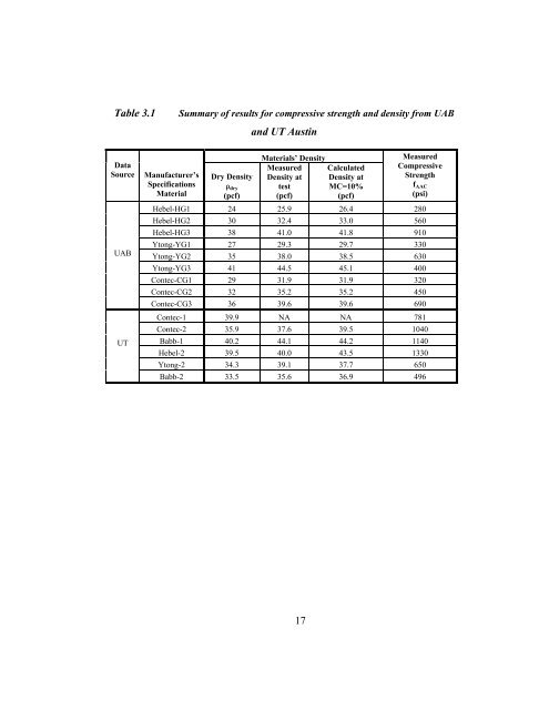
- Page 13 and 14: List of Tables Table 3.1 Summary of
- Page 15 and 16: Figure 3.18 Modulus of rupture vers
- Page 17 and 18: of AAC, but after 1950, AAC did suc
- Page 19 and 20: Because RILEM methods of test are n
- Page 21 and 22: Within that overall scope of work,
- Page 23 and 24: CHAPTER 2 Background of Available D
- Page 25 and 26: 2.3.2 Data from The University of A
- Page 27 and 28: obtained from Ytong 4 . Results fro
- Page 29 and 30: CHAPTER 3 Evaluation and Synthesis
- Page 31: average requirements, and a few tes
- Page 35 and 36: Excluding Ytong G3 increases the co
- Page 37 and 38: 3.3 STRESS-STRAIN BEHAVIOR AND MODU
- Page 39 and 40: The relationship between modulus an
- Page 41 and 42: E = 0 .3 f AAC + 105 Equation (3.1)
- Page 43 and 44: 3.4 TENSILE STRENGTH OF AAC 3.4.1 I
- Page 45 and 46: Stresses perpendicular to rise P St
- Page 47 and 48: tensile strength and compressive st
- Page 49 and 50: The Dutch standard NEN 3838 7 provi
- Page 51 and 52: a moisture content of 10%, a conven
- Page 53 and 54: Table 3.7 Modulus of Rupture - UAB
- Page 55 and 56: 200 UT UT UT UT UAB UT fr (psi) 100
- Page 57 and 58: UAB 300 200 UAB UAB UAB RILEM (Eq.
- Page 59 and 60: As discussed in Section 3.4.4, the
- Page 61 and 62: also include results from adding th
- Page 63 and 64: mortar joint. The limit tensile bon
- Page 65 and 66: 3.7 SHEAR BOND BETWEEN AAC AND THIN
- Page 67 and 68: Table 3.10 Shear Tests on AAC with
- Page 69 and 70: UT Austin conducted 11 direct shear
- Page 71 and 72: 200 AAC-ovendry (MC=10%) AAC-airdry
- Page 73 and 74: Table 4.1 Organization of primary r
- Page 75 and 76: earing of the cross wires against t
- Page 77 and 78: The implications of this prediction
- Page 79 and 80: calculate the minimum number of equ
- Page 81 and 82: V u V V u max = = Equation (4.11)
- Page 83 and 84:
4.4.3 Flexural Design of Tension- a
- Page 85 and 86:
1) Short-term deflections should be
- Page 87 and 88:
4.6.2 Shear Strength provided by Sh
- Page 89 and 90:
Table 4.3 Summary of predicted and
- Page 91 and 92:
4.7.2 Control of Deflections This p
- Page 93 and 94:
c y AAC in compression n. a. 1 in.
- Page 95 and 96:
i) Try if h = 12 in. satisfies Sect
- Page 97 and 98:
4.7.3 Shear capacity Determine fact
- Page 99 and 100:
T T = A s f y = 0.36 = ( 80) 28.8 k
- Page 101 and 102:
CHAPTER 5 Summary, Conclusions and
- Page 103 and 104:
materials (f AAC ′ ≤ 450 psi) t
- Page 105 and 106:
APPENDIX A Design Provisions for Re
- Page 107 and 108:
long, 8.2 ft (2.5 m) tall and 9.5 i
- Page 109 and 110:
V V V V AAC AAC AAC AAC ' Pu = 0 .9
- Page 111 and 112:
Table A.4 Initial predictions of ca
- Page 113 and 114:
V obs / V AAC 1.2 1.0 0.8 0.6 0.4 0
- Page 115 and 116:
Table A.5 Prediction of capacity as
- Page 117 and 118:
A.1.2 Flexure-Shear Cracking for AA
- Page 119 and 120:
observed in the 6 flexure-dominated
- Page 121 and 122:
Table A.8 Results for flexure-shear
- Page 123 and 124:
30 133 20 89 10 44 0 -0.6 -0.4 -0.2
- Page 125 and 126:
Applied lateral load Vertical tie d
- Page 127 and 128:
is related by geometry to the force
- Page 129 and 130:
lateral load was higher than the pr
- Page 131 and 132:
perpendicular to the crack and the
- Page 133 and 134:
160 712 120 534 Total base shear (k
- Page 135 and 136:
f base shear is zero. For example,
- Page 137 and 138:
The measured axial load in Figure A
- Page 139 and 140:
Observed versus predicted nominal f
- Page 141 and 142:
theoretical and design methodologie
- Page 143 and 144:
L Figure A.28 Behavior of monolithi
- Page 145 and 146:
A.2.2 Verification of Shear Capacit
- Page 147 and 148:
(A.3) to predict web-shear cracking
- Page 149 and 150:
1.6 1.4 1.2 1 0.8 shear wall will r
- Page 151 and 152:
A.2.5 Analysis to Determine if Long
- Page 153 and 154:
to reaching the nominal flexural ca
- Page 155 and 156:
Figure A.35 Loss of end block on co
- Page 157 and 158:
After the initial adhesion between
- Page 159 and 160:
Centerline of grouted cell σ radia
- Page 161 and 162:
12.1.3 - The maximum ratio of verti
- Page 163 and 164:
Plan View N Applied lateral load A
- Page 165 and 166:
corresponding lengths of grout and
- Page 167 and 168:
lower fractile of the observed shea
- Page 169 and 170:
The required ratio of reinforcing b
- Page 171 and 172:
A.4 DESIGN EXAMPLES A.4.1 Design of
- Page 173 and 174:
M n = T 1 ⎛ l w ⎜216 − ⎝ 2
- Page 175 and 176:
φ V AAC ( 240) ⎛ 3 ⎞ 90 ⎜
- Page 177 and 178:
Fu l 18000 ⋅ 92 M = = = 414,000lb
- Page 179 and 180:
F u Node 1 Node 3 Tension reinforce
- Page 181 and 182:
The reinforcement ratio limit of 3%
- Page 183 and 184:
Try #5 bar: T = A s f y = 0.31⋅ 6
- Page 185 and 186:
The factored splitting tensile stre
- Page 187 and 188:
B.1.2 Typical Mechanical and Therma
- Page 189 and 190:
B.1.5 Scope and Objectives of this
- Page 191 and 192:
h) Reinforcement (ASTM A82), welded
- Page 193 and 194:
Figure B.5 Cutting AAC into desired
- Page 195 and 196:
Figure B.7 Packaging of finished AA
- Page 197 and 198:
Table B.3 Dimensions of plain AAC w
- Page 199 and 200:
B.3 STRUCTURAL DESIGN OF REINFORCED
- Page 201 and 202:
B.3.2.2 Combinations of Flexure and
- Page 203 and 204:
The shear resistance due to the AAC
- Page 205 and 206:
c) Immediately after placing the fi
- Page 207 and 208:
B.4.5 Exterior Finishes for AAC Unp
- Page 209 and 210:
B.4.6.4 Ceramic Tile When ceramic w
- Page 211 and 212:
B.5.1.1 B.5.1.1.1 Exterior Horizont
- Page 213 and 214:
B.5.1.2 B.5.1.2.1 Exterior Vertical
- Page 215 and 216:
B.5.1.3 B.5.1.3.1 Typical Vertical
- Page 217 and 218:
B.5.1.4.2 Typical Vertical Panel La
- Page 219 and 220:
B.5.2 Load Bearing Vertical Wall Pa
- Page 221 and 222:
B.5.2.1.2 Typical Vertical Joint Pr
- Page 223 and 224:
B.5.2.2.2 Exterior Wall Section for
- Page 225 and 226:
B.5.2.3 B.5.2.3.1 Interior Bearing
- Page 227 and 228:
B.5.2.5 B.5.2.5.1 Intersection of A
- Page 229 and 230:
B.5.3 Floor and Roof B.5.3.1 Minimu
- Page 231 and 232:
B.5.3.3 Interior Floor Panel Suppor
- Page 233 and 234:
B.5.3.5 B.5.3.5.1 Floor Panel at Co
- Page 235 and 236:
B.5.3.6 Allowable Sizes and Locatio
- Page 237 and 238:
APPENDIX C Proposed Code Design Pro
- Page 239 and 240:
Chapter 3 — Materials Add the fol
- Page 241 and 242:
Chapter 4 -- Durability Requirement
- Page 243 and 244:
measurement tube reference tube 12
- Page 245 and 246:
(c) Reinforcement shall be clean of
- Page 247 and 248:
Chapter 6 -- Formwork, Embedded Pip
- Page 249 and 250:
Chapter 8 — Analysis and Design
- Page 251 and 252:
Chapter 9 — Strength and Servicea
- Page 253 and 254:
Chapter 10 - Flexure and Axial Load
- Page 255 and 256:
Add the following to Section 11.5.6
- Page 257 and 258:
Remove Section 11.10.7 and replace
- Page 259 and 260:
Add new Section 12.20: 12.20 - Desi
- Page 261 and 262:
Delete Chapter 15. Chapter 16 — P
- Page 263 and 264:
16.5.1.2.3.1 — Compression struts
- Page 265 and 266:
16.5.2.2 — Longitudinal ties para
- Page 267 and 268:
Chapter 21 - Special Provisions for
- Page 269 and 270:
APPENDIX E - NOTATION Add the follo
- Page 271 and 272:
Chapter 4 -- Durability Requirement
- Page 273 and 274:
Delete Chapter 6 and replace by the
- Page 275 and 276:
Chapter 8 — Analysis and Design
- Page 277 and 278:
Chapter 9 — Strength and Servicea
- Page 279 and 280:
Chapter 10 - Flexure and Axial Load
- Page 281 and 282:
R11.5.6.9 — In traditional reinfo
- Page 283 and 284:
AAC. Direct shear tests performed a
- Page 285 and 286:
(Tanner 2003) showed that vertical
- Page 287 and 288:
A s F s f aac d cross f aac d cross
- Page 289 and 290:
Delete Chapter 15. Chapter 16 — P
- Page 291 and 292:
diaphragm can also be determined by
- Page 293 and 294:
Ring beam Interior grouted cavity L
- Page 295 and 296:
Chapter 21 — Special Provisions f
- Page 297 and 298:
The stress-strain curves for each s
- Page 299 and 300:
1.6 1.4 1.2 Stress (ksi) 1 0.8 0.6
- Page 301 and 302:
Table D.1 Calculated modulus of rup
- Page 303 and 304:
P Joint length Specimen height P 2
- Page 305 and 306:
Figure D.10 Failure surface of Dire
- Page 307 and 308:
is 0.8, with a COV of 8%. A 10% low
- Page 309 and 310:
) All cross-wires that cross the we
- Page 311 and 312:
RILEM Recommended Practice, E & FN