as PDF-Download - Osstem.
as PDF-Download - Osstem.
as PDF-Download - Osstem.

Create successful ePaper yourself
Turn your PDF publications into a flip-book with our unique Google optimized e-Paper software.
c OSSTEM IMPLANT Co., Ltd.<br />
1 st edition published at 1th April 2006<br />
2 nd edition published at 14 th Feb 2013<br />
Published by Choi, Kyoo-ok<br />
Edited by Kim, Young-kyun, Kim, Ki-Seong, Kim, Se-woung, Park, Hwee-Woong<br />
Oh, Young-Hak, Lee, Dae-Hee, CHO, Yong-Seok<br />
Publisher : <strong>Osstem</strong> Implant Co., Ltd.<br />
Registration No. 2005-5<br />
Address : 8th floor, World Meridian 2, 426-5 G<strong>as</strong>an-dong, Geumcheon-gu,<br />
Seoul, Korea<br />
Telephone : 82-2-2016-7000<br />
Fax : 82-2-2016-7001<br />
Web-site : http://www.osstem.com<br />
E-mail : m<strong>as</strong>ter@osstem.com<br />
Manufactured by adfarm Communication<br />
Printed by Grabic Co., Ltd. 031-901-2982<br />
Price : 100,000 Won<br />
All rights reserved <strong>Osstem</strong> Implant Co., Ltd. Reproducing,<br />
using, and lifting excerpts from the content, figures, and photos<br />
in this book are strictly prohibited and are punishable by law.
CEO’s MESSAGE<br />
I am very happy to publish revised edition of<br />
2013 OSSTEM IMPLANT SYSTEM.<br />
OSSTEM IMPLANT CEO<br />
Choi, Kyoo-Ok (DDS, Ph.D.)<br />
Korea’s dental implant studies were introduced considerably later than in Europe or America.<br />
However, thanks to Korea’s high standard of dentistry, dentists’academic fervor, and incre<strong>as</strong>e in the general public’s<br />
interest for oral health h<strong>as</strong> developed academics and industry, resulting in a rapid popularization of implants. Not only<br />
do all universities perform implant operations, but also over 80% of private clinics. Korea’s implant clinic h<strong>as</strong> been<br />
growing and developing into a world-cl<strong>as</strong>s level.<br />
<strong>Osstem</strong> Implant h<strong>as</strong> been spearheading such trend of growth and evolution, providing clinical operation methods and<br />
clinical technical intelligence to AIC workshops, regional research societies, <strong>as</strong> well <strong>as</strong> various conferences. By<br />
publishing general introduction to OSSTEM IMPLANT SYSTEM in 2005 and five general introductions to OSSTEM<br />
IMPLANT SYSTEM in 2006, <strong>Osstem</strong> Implant h<strong>as</strong> been contributing to the improvement of clinical operation methods<br />
and the development of academics.<br />
It h<strong>as</strong> been 7 years since the publication of total five general introductions to OSSTEM IMPLANT SYSTEM, and <strong>Osstem</strong><br />
Implant h<strong>as</strong> been striving for the clinical development of implants by continual research and development,<br />
development of new technology, and provision of more convenient, safe, and durable products to both dentists and<br />
patients for quality improvement.<br />
B<strong>as</strong>ing on years of c<strong>as</strong>es with new concepts of operative methods applied, in addition to the rele<strong>as</strong>e of such new<br />
technology and products, a revised edition of OSSTEM IMPLANT SYSTEM h<strong>as</strong> been published.
This revision, published after 7 years, bear different significance from first edition of general introduction of 2005 and<br />
from 5 particulars rele<strong>as</strong>ed in 2006 when implant w<strong>as</strong> being popularized.<br />
This revised edition is not a mere update from OSSTEM IMPLANT SYSTEM, but an upgrade revision, which exhibits<br />
enhanced convenience in operation and long term clinical results by applying improved <strong>Osstem</strong> implant’s design and<br />
new products with improved surface treatment. Moreover, it is a guideline organized to show operative methods of<br />
experienced clinicians, so that clinicians can utilize state of the art surgical tools and equipment<br />
The revised edition consists of “ Variety, Design, and Surface Treatment of <strong>Osstem</strong> Implant ”, “Implant Operation ”,<br />
“Implant Prosthesis ”, “Surgical preparation and instrument management ”, “Clinical c<strong>as</strong>es ”, “Related Articles ”and<br />
etcetera. Because it includes detailed accounts of real clinical application processes b<strong>as</strong>ed on <strong>Osstem</strong> Implant’s<br />
product’s technical understanding, it is expected to provide immediate and realistic clinical guidelines to private<br />
clinicians.<br />
To the hard work of those who helped greatly to publish this book with liberal clinical verifications and researches: Prof.<br />
Kim young-Kyun, Dr. Oh Young-Hak, Dr. Cho Yong-Seok, Dr. Lee Dae-Hee, Dr. Kim Ki-Seong, Dr. Park Hwee-Woong,<br />
Dr. Kim Se-Woung, I give special thanks. Moreover, I thank the AIC directors and the dentists in the country who have<br />
provided valuable clinical c<strong>as</strong>es and numerous feedbacks.<br />
I give thanks to my fellow dentists and admire their p<strong>as</strong>sion and dedication that helped <strong>Osstem</strong> implant achieve global<br />
excellence.<br />
This book is a product of <strong>Osstem</strong> implant’s development, <strong>as</strong> well <strong>as</strong> a determination to lead the international dental<br />
community <strong>as</strong> a representative of Korea. Through unrelenting effort and research, we promise to return with even<br />
better products and technology.<br />
Thank you.
Editor’s note<br />
Editor in Chief<br />
Since <strong>Osstem</strong>’s first development of domestic implant in 1992, the first patent for<br />
dental implant in Korea w<strong>as</strong> obtained in 1995 through continuous research. It<br />
w<strong>as</strong> rele<strong>as</strong>ed <strong>as</strong> AVANA since 1997, and I began to cautiously use domestic<br />
implants. However, I w<strong>as</strong> hesitant <strong>as</strong> I had a vague sense of mistrust and<br />
discomfort regarding domestic products. Nevertheless, after confirming the<br />
excellent initial osseointegration and functional maintenance after prosthesis<br />
treatment, I started to actively use domestic implants. Since then, the company<br />
name changed to <strong>Osstem</strong> Implant, and surface treatment w<strong>as</strong> continuously<br />
developed and products of various designs were rele<strong>as</strong>ed. Moreover, numerous<br />
scholars reported on the fundamental and clinical research results, and <strong>as</strong> both<br />
domestic and international academic journals recently publish <strong>Osstem</strong> Implant<br />
related journals, intermediate to long term stability h<strong>as</strong> been confirmed.<br />
Kim, Young-Kyun<br />
General introduction to OSSTEM IMPLANT published in 2005 w<strong>as</strong> acclaimed <strong>as</strong><br />
the first book in which a company h<strong>as</strong> organized its implants. In 2006, revised<br />
introduction in Korean, Taiwanese, and English w<strong>as</strong> published, and itemized<br />
discussions of operation, prosthesis, prosthetic lab-work, and esthetic implant<br />
have also been published, providing valuable resources not only to the implant<br />
community but also to the dentists.<br />
The material published in 2013 records in detail the history of <strong>Osstem</strong> Implant,<br />
types and characteristics of fixtures, surgical instruments and procedures, and<br />
discusses in depth the concept of b<strong>as</strong>ic implant prothodontics, occlusion, and<br />
impression taking. Successful clinical c<strong>as</strong>es from domestic scholars who used<br />
<strong>Osstem</strong> Implants are introduced, and <strong>Osstem</strong> Implant related international<br />
academic articles have also been included. This teaching material, I believe, is<br />
not merely limited to <strong>Osstem</strong> Implant system, but could aid in the fundamental<br />
understanding of implantology <strong>as</strong> well <strong>as</strong> <strong>as</strong>sist the clinicians who use the<br />
products of other companies.<br />
I sincerely thank the editors and <strong>Osstem</strong> Implant faculties who have spent a year<br />
editing and collecting resources, <strong>as</strong> well <strong>as</strong> the dentists who have provided<br />
numerous clinical data. Moreover, I thank the Adfarm Communication executives<br />
and staff who have showed devoted support in providing this book.<br />
Jan. 2013 Kim, Young-Kyun, Editor in Chief
Editorial Board<br />
CEO<br />
<strong>Osstem</strong> Implant Co., Ltd.<br />
쪾DDS, College of Dentistry, Seoul National University, Seoul, Korea<br />
쪾MS, Dankook University , Major: Orthodontics, Seoul, Korea<br />
쪾Ph.D, College of Medicine, Korea University, Seoul, Korea<br />
쪾CEO and President, <strong>Osstem</strong> Implant Co., Ltd., Seoul, Korea<br />
쪾The Director of a Apsun Dental Clinic<br />
쪾Adjunct Professor, Korea Medical University<br />
쪾Vice President of Korea Venture Business Association.<br />
쪾Director of Korea Medium Industries Association<br />
쪾Director of Kosdaq Association<br />
CEO<br />
Choi, Kyoo-Ok<br />
Editor in Chief<br />
Seoul National University Bundang Hospital<br />
Kim, Young-Kyun<br />
D.D.S., PhD<br />
쪾1980 - 1986 Seoul National University, College of Dentistry. D.D.S.<br />
쪾1986 - 1989 Intern, Resident, Depart of Oral and Maxillofacial Surgery,<br />
Section of Dentistry, Seoul National University Hospital<br />
쪾1989 - 1992 Military Dental Officer<br />
쪾1987 - 1994 Seoul National University Graduate Course. MSD. PhD.<br />
쪾1992 -1 997 Full-time Lecturer, Assistant Professor, Dept. of Oral and Maxillofacial Surgery,<br />
College of Dentistry, Chosun University<br />
쪾1997 - 2003 Chairman, Dept. of Oral and Maxillary Surgery, Section of Dentistry,<br />
Bundang Jesaeng General Hospital<br />
쪾2003 ~ Now Associate Professor, Chairman, Dept. of Oral and Maxillofacial Surgery,<br />
Section of Dentistry, Seoul National University Bundang Hospital<br />
Associate Professor, School of Dentistry, Seoul National University<br />
쪾2011 ~ Now Editor-in-Chief, J Korean Assoc Oral Maxillofac Surg<br />
쪾Published articles: 447 articles including "Development of a novel bone grafting material<br />
using autogenous teeth" International articles : 51 articles including<br />
"Development of a novel bone grafting material using autogenous teeth"<br />
쪾Writing textbooks: publishing 54 books including "bone graft and implant vol. 1, 2, 3."<br />
06
Editors<br />
Apsun Dental Hospital<br />
CHO, Yong-Seok<br />
DDS, MSD, PhD<br />
쪾 Graduated in 1989 from the Dental Collage of Seoul National University, Korea<br />
쪾 Trained at Dept. of Oral and maxillofacial Surgery, Seoul National University Hospital<br />
쪾 Assistant professor at Chungbuk National University<br />
쪾 Chairman of Dept. of Dentistry, Chungbuk National University Hospital<br />
쪾 Diplomate, Korean board of Oral & maxillofacial Surgery<br />
쪾 Diplomate, Korean Board of Maxillofacial Pl<strong>as</strong>tic and Reconstructive Surgery<br />
쪾 <strong>Osstem</strong> Faculty and Course Director of AIC (Apsun Dental Implant Research and Education Center)<br />
쪾 AO active member<br />
쪾 EAO member<br />
쪾 Ambulatory professor of Seoul National University Dental Collage<br />
쪾 Director of Apsun Dental Hospital<br />
Namsang Dental Clinic<br />
Educational and Professional Training<br />
쪾 1988 D.D.S. College of Dentistry, Seoul National University<br />
쪾 1988 - 1991 Internship & Resident, Dept. of Prosthodontics, Seoul National University Dental Hospital<br />
쪾 1991 M.S.D. Graduate School of Dentistry, Seoul National University<br />
쪾 2010 Ph.D. Graduate School of Dentistry, Seoul National University<br />
쪾 2008 - 2012 Clinical Professor, Dept. of Prosthodontics, College of Dentistry, Seoul National University<br />
쪾 Present Director of Namsang Dental Clinic<br />
Director<br />
Kim, Ki-Seong<br />
Organization<br />
Vice President, Korean Academy of Esthetic Dentistry (KAED)<br />
Korean Academy of Prosthodontics<br />
Academy of Osseointegration<br />
Asian Academy of Osseointegration<br />
Seoul Implant Research & Study Group<br />
The Wise Dental Clinic<br />
Director<br />
Kim, Se-Woung<br />
Educational and Professional Training<br />
쪾 Graduated from Kyung Hee University’s College of Dentistry<br />
쪾 Interned at the Department of Prosthodontics of Gacheon University Gil Medical Center<br />
쪾 Dentist accredited by the Korean Association of Orthodontists<br />
쪾 Served <strong>as</strong> general affairs director of the Korean Association of Oral and Maxillofacial Implant - Incheon Branch<br />
쪾 Served <strong>as</strong> director of the Korea Academy of Aesthetic Dentistry<br />
쪾 Served <strong>as</strong> clinical advisor on prosthetic dentistry at Gacheon University’s Dental Hygiene Department<br />
쪾 Served <strong>as</strong> clinical advisor at the Department of Prosthodontic Dentistry, Graduate School of Health Science<br />
Gacheon University<br />
쪾 Director, OSSTEM AIC Society for Research<br />
쪾 Currently serves <strong>as</strong> manager at the Department of Prosthesis at Gacheon University of Science and Medicine<br />
쪾 Director of The wise dental hospital<br />
07
Editors<br />
Seoul Dental Clinic<br />
쪾 Seoul National University Dental College & Graduate school D.D.S M.S Ph.D<br />
쪾 Seoul National University Dental College Adjunct Professor<br />
쪾 Inje University Sanggye Baik Hospital Adjunct Professor<br />
쪾 F & I Implant Research Group Honorary President <strong>Osstem</strong> Implant AIC Director<br />
쪾 Seoul Dental Clinic Director<br />
Director<br />
Lee, Dae-Hee<br />
All Dental Clinic<br />
쪾 D.D.S/M.S.D from School of Dentistry, Seoul National University<br />
쪾 Department of Prosthodontics, Seoul National University Dental Hospital<br />
쪾 Adjunct Professor, College of Dentistry, Seoul National University<br />
쪾 All Dental Clinic Director<br />
Director<br />
Oh, Young-Hak<br />
Seoul Ace Dental Clinic<br />
쪾 D.D.S/M.S.D from School of Dentistry, Seoul National University<br />
쪾 Department of Prosthodontics, Seoul National University Dental Hospital<br />
쪾 Adjunct Professor, College of Dentistry, Seoul National University<br />
쪾 Seoul Ace Dental Clinic Director<br />
Director<br />
Park, Hwee-Woong<br />
08
OSSTEM IMPLANT SYSTEM<br />
CONTENTS<br />
Ⅰ Kinds and design of <strong>Osstem</strong> implant system<br />
Ⅱ Surface Treatment<br />
Ⅲ Implant Surgery<br />
11<br />
69<br />
91<br />
1. Surgical guideline of <strong>Osstem</strong> implant systems<br />
1) TSIII SA Implant System<br />
2) MS Implant System<br />
3) Ultra-Wide Implant System<br />
92<br />
104<br />
112<br />
2. Surgical kits for sinus bone graft<br />
1) The CAS (Crestal Approach Sinus)-KIT<br />
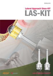
2) The LAS(Lateral Approach Sinus)-KIT<br />
3. Guided Bone Regeneration Using the SMARTbuilder<br />
4. AutoBone Collector ( A.B.C )<br />
5. Drilling Sequence of <strong>Osstem</strong> Implant System<br />
Ⅳ Implant Prosthodontics<br />
120<br />
141<br />
147<br />
155<br />
160<br />
177<br />
1. Introduction<br />
1) Introduction of implants in prosthodontics and its significance<br />
2) Selection of implant<br />
3) Types and selection of implant prosthesis<br />
4) Types of <strong>Osstem</strong> implant abutment<br />
5) Selection of implant abutment<br />
178<br />
180<br />
182<br />
184<br />
223<br />
2. Impression taking for implant superstructure<br />
1) B<strong>as</strong>ic concepts of impression taking for implants<br />
2) Time for impression taking<br />
3) Method for implant impression taking<br />
4) Summary-impression taking in TS implant system.<br />
235<br />
238<br />
241<br />
299<br />
3. Guideline for occlusion of implant prosthodontics<br />
1) Occlusion, the never-ending challenge for dentists<br />
2) Formation process of occlusion concept in implant<br />
302<br />
302<br />
prosthodontics and current condition<br />
3) Osseoperception<br />
4) Occlusion=Force controll<br />
5) Detailed occlusion patterns depending on number and positions<br />
305<br />
306<br />
314<br />
of teeth to rehabilitate<br />
6) Summary<br />
Ⅴ Surgical preparation and instrument management for implant<br />
Ⅵ Clinical C<strong>as</strong>es of <strong>Osstem</strong> Implant System<br />
Ⅶ <strong>Osstem</strong> Implant Related Paper<br />
324<br />
327<br />
345<br />
431<br />
09
Ⅰ Kinds and design of <strong>Osstem</strong> implant system<br />
It w<strong>as</strong> named AVANA implant in 1995 after machined surface straight standard implant w<strong>as</strong> first launched.<br />
Self tapping implant that h<strong>as</strong> been TiO2 bl<strong>as</strong>ting treated w<strong>as</strong> then launched.. Company name changed to<br />
<strong>Osstem</strong> Implant at the end of 1997, and one stage implant MT I and MT II were rele<strong>as</strong>ed in 1997~2001. At<br />
the moment, two-stage implant with straight body w<strong>as</strong> named US II. Since then, continuous R&D lead to<br />
surface treated products <strong>as</strong> RBM, SA, HA, BA, CA, and products with various designs <strong>as</strong> USIII, SSI, SS II,<br />
SSIII, GSII, GSIII, TSII, TSIII, TSIV, Ultra-Wide, MS system. (Table1) (Fig1)<br />
Table 1. History of the development of <strong>Osstem</strong> implant and related products<br />
2012<br />
2011<br />
06 Development of TSIII CA Implant<br />
04 Development of TSIII BA Implant<br />
07 Development of CustomFit Abutment<br />
04 Development of LAS-KIT<br />
2010<br />
06 Development of TSIII HA Implant<br />
Development of CAS-KIT<br />
04 Development of OSSTEM Guide<br />
03 Development of TSIII SA Implant<br />
2009<br />
2008<br />
2007<br />
2005<br />
2004<br />
06 Start domestic sale of HIOSSEN Implant (USA)<br />
05 Development of New SSIII Implant<br />
01 Developed and patented PEP7(strong osteoinductive material)<br />
06 Development of GSIII Implant<br />
03 Development of MS Implant<br />
05 Development of GSII Implant<br />
11 Development of SSIII Implant<br />
07 Development of USIII Implant<br />
2002<br />
2001<br />
2000<br />
1997<br />
1995<br />
1992<br />
10 Development of SSII Implant<br />
08 Development of USII Implant<br />
01 Authorized <strong>Osstem</strong> Implant R & D Center<br />
Established AIC(Apsun Dental Implant Research & Education Center)<br />
Establishment of <strong>Osstem</strong> Implant Inc., trade name change (<strong>Osstem</strong> Implant)<br />
M<strong>as</strong>s production and sale of AVANA implant (SooMin general dental material)<br />
Self-development of implant successful and acquired license for industrial manufacture<br />
Promoted self-development of dental implant<br />
12
OSSTEM IMPLANT SYSTEM<br />
Fig.1 History of the development of <strong>Osstem</strong> Implant<br />
13
Ⅰ Kinds and design of <strong>Osstem</strong> implant system<br />
In the beginning, <strong>Osstem</strong> implant launched submerged type US(Universal Solution) series (USII, USIII) which h<strong>as</strong><br />
external hexagon connection type, and non-submerged type SS(Success Solution) series (SSI, SSII, SSIII) which<br />
h<strong>as</strong> internal connection type. These implants are still being used today. Since 2005, tapered bodied GS (Gorgeous<br />
solution) (GSII, GSIII) and TS(Transcendent Solution) (TSII, TSIII, TSIV) series which have tapered conical sealing<br />
connection type and are capable of both submerged and non-submerged installation were launched. (Fig. 2-5)<br />
USII RBM USIII RBM USII SA USIII SA<br />
Fig. 2. USII RBM, USIII RBM, USII SA, USIII SA<br />
SSII RBM SSIII RBM SSII SA SSIII SA<br />
Fig. 3. SSII RBM, SSIII RBM, SSII SA, SSIII SA<br />
14
OSSTEM IMPLANT SYSTEM<br />
Depending on fixture body shape, it is divided into straight type and tapered type. Straight body h<strong>as</strong> the<br />
symbol “II”, where<strong>as</strong> tapered body h<strong>as</strong> the symbol “III”. Recommended insertion torque for all <strong>Osstem</strong><br />
implant is below 40Ncm.<br />
GSII<br />
GSIII<br />
Fig. 4. GSII, GSIII<br />
TSII TSIII TSIV<br />
Fig. 5. TSII, TSIII, TSIV<br />
15
Ⅰ Kinds and design of <strong>Osstem</strong> implant system<br />
1. US (Universal Solution) System<br />
Hybrid RBM surfaces that are useful for plaque control were supplied in the early stages, (Fig. 6) but<br />
from 2006, systems that have all their surfaces RBM treated <strong>as</strong> USII, III Plus system are supplied and<br />
used. (Fig. 7) Recently, RBM, SLA surface treated products are both available.<br />
3mm<br />
Fig. 6. Hybrid RBM treated old USII system. It h<strong>as</strong> 3mm<br />
machined surface from platform<br />
Fig. 7. All surfaces RBM treated USII system<br />
Depending on surface treatment and design, RBM, USIII RBM, USII SA, USIII SA, USIV SA<br />
are supplied. (Fig. 8)<br />
USII RBM<br />
USII RBM<br />
(AII RBM)<br />
USIII RBM USII SA USIII SA USIV SA<br />
Fig. 8. Various US Implant System<br />
16
OSSTEM IMPLANT SYSTEM<br />
1) USII<br />
(1) Characteristics (Fig. 9)<br />
USII RBM specifications are: 0.6pitch X 0.25~0.4depth X Single thread thread pitch 0.6mm, thread<br />
depth 0.25-0.4mm, single thread (single rotation inserts single thread pitch)]. USII SA<br />
specifications are: 0.8pitch X 0.4~0.5depth X Double thread [thread pitch 0.8mm, thread depth<br />
0.4-0.5mm, double thread (single rotation inserts two thread pitch)].<br />
1 External Hexagon Connection Method<br />
Hexagon’s precision is +0.003/-0.005mm, fixture hex and superstructure’s tolerance is 7~15μm, abutment’s<br />
rotation tolerance is 0.4°~ 2°, and thus shows excellent precision fitness.<br />
2 Is a straight body structure, and is a submerged type implant that fundamentally needs two-stage<br />
installation. However, one-stage surgery is possible depending on indication.<br />
3 On the lower part of fixture, RBM specification h<strong>as</strong> 4 cutting edges and SA specification h<strong>as</strong> 3 cutting edges<br />
which allows self-tapping. Slanted end of fixture also provides excellent initial entry when installing.<br />
4 Screw thread consists of 0.6 pitch triangular screw.<br />
5 Diameter of platform and size of hexagon are same and therefore compatible with upper material of<br />
Branemark and BIOMET 3i Osseotite.<br />
Sand-bl<strong>as</strong>ted Acid-etching<br />
Corkscrew Thread<br />
쪾 0.8pitch x 0.5depth(0.35depth) x double thread<br />
쪾 Synchronized thread<br />
쪾 Optimized design for SA surface<br />
쪾 Powerful self threading<br />
쪾 High initial stability<br />
Apical<br />
쪾 Good digging ability<br />
쪾 Good fixing ability at lower part<br />
Straight Body<br />
쪾 Implantation performance<br />
쪾 E<strong>as</strong>y surgical protocol<br />
쪾 Decre<strong>as</strong>e sensitivity on drill size<br />
Cutting Edge<br />
쪾 Excellent Self Tapping ability<br />
Fig. 9. USII SA fixture<br />
17
Ⅰ Kinds and design of <strong>Osstem</strong> implant system<br />
(2) Specification<br />
Various fixture length of 6, 7, 8.5, 10, 11.5, 13, 15mm and diameter of 3.5, 4.0, 4.5, 5.0mm are available.(Table 2,<br />
3) (Fig. 10-13). As shown in image, USII RBM and USII SA differ slightly in length. USII SA’s platform’s actual<br />
diameter is 0.1mm larger than nominal diameter.(Fig. 14, 15) By applying a bigger platform than body<br />
diameter, when installing, it adds a stopping function <strong>as</strong> well <strong>as</strong> a platform switching effect.(Fig. 16)<br />
Table 2. Specification of USII SA<br />
Connection Mini Regular Wide PS Wide<br />
Platform P3.5 P4.1 P5.0 P5.1<br />
Hex 2.4 2.7 2.7 3.4<br />
Diameter Ø3.5 Ø4.0 Ø4.5 Ø5.0 Ø5.0<br />
- - - 6 6<br />
- 7 7 7 7<br />
Length<br />
8.5 8.5 8.5 8.5 8.5<br />
10 10 10 10 10<br />
11.5 11.5 11.5 11.5 11.5<br />
13 13 13 13 13<br />
Table 3. Specification of USII RBM<br />
Connection Mini Regular Wide PS Wide<br />
Platform P3.5 P4.1 P5.0 P5.1<br />
Hex 2.4 2.7 2.7 3.4<br />
Diameter Ø3.3 Ø3.75 Ø4.0 Ø4.5 Ø5.0 Ø5.5 Ø5.0 Ø5.5<br />
- 7 7 7 7 7 7 7<br />
8.5 8.5 8.5 8.5 8.5 8.5 8.5 8.5<br />
Length<br />
10 10 10 10 10 10 10 10<br />
11.5 11.5 11.5 11.5 11.5 11.5 11.5 11.5<br />
13 13 13 13 13 13 13 13<br />
15 15 15 15 15 15 15 15<br />
18
M R W Fixture Platform OSSTEM IMPLANT SYSTEM<br />
Fig. 10. USII SA Mini Fixtures<br />
Fig. 11. USII SA Regular Fixtures<br />
Fig. 12. USII SA Wide Fixtures<br />
19
Ⅰ Kinds and design of <strong>Osstem</strong> implant system<br />
Fig. 13. Pre-mounted USII SA fixture<br />
Length 11.5mm <strong>as</strong> Standard<br />
0.75 0.2<br />
11.1<br />
11.5<br />
USII RBM<br />
USII SA<br />
Fig. 14. USII 11.5mm implant specification.<br />
USII RBM and USII SA have slightly different<br />
structures.<br />
SA 13mm vs RBM 15mm<br />
USII RBM<br />
15mm<br />
USII SA<br />
13mm<br />
15mm is not available in USII SA<br />
1. SA Surface is better than RBM<br />
2. Bone contact of SA 13mm is similar to RBM 15mm<br />
3. Demand of 15mm is low<br />
Fig. 15. Comparison of USII RBM 15mm and<br />
USII SA 13mm. It is recommended to install<br />
USII RBM 0.75mm supracrestal, and USII SA<br />
0.2mm supracrestal. In such c<strong>as</strong>e, bone<br />
contact area does not differ much. Hence,<br />
USII SA does not have specification with<br />
length of 15mm.<br />
20
OSSTEM IMPLANT SYSTEM<br />
Fixture Platform is bigger than Body diameter (Fixture Ø3.5, Ø4.0)<br />
Fixture Platform is 0.1mm bigger than Abutment diameter<br />
쪾 Stop function on fixture<br />
insertion<br />
쪾 Platform switching effect<br />
(prevent bacterial inv<strong>as</strong>ion)<br />
쪾 Secure long term stability<br />
(secure strength)<br />
Platform<br />
Platform Mini Regular Wide PS Wide<br />
Nominal diameter P3.5 P4.1 P5.0 P5.1<br />
Actual diameter Ø3.6 Ø4.2 Ø5.1 Ø5.2<br />
Fig. 16. Platform specification of USII SA. Actual diameter is 0.1mm bigger than nominal diameter. By applying a bigger platform<br />
than body diameter, when installing, it adds a stopping function <strong>as</strong> well <strong>as</strong> a platform switching effect.<br />
(3) Drilling and Implant installation<br />
Guideline from manufacturer should be followed. Recommended installation torque is below 40Ncm, and use<br />
of fixture over 4.5mm diameter is suggested for single implant c<strong>as</strong>es for posterior region. Install USII RBM via<br />
supra-crestal method, and USII SA should be installed via equi-crestal method. One must drill additionally or<br />
countersink when installing sub-crestally. Using hand ratchet and causing excessive torque near platform<br />
where over-torque had occurred after implant installation.(Fig. 17)<br />
Fig. 17. Periapical radiograph of USII hybrid<br />
surface 74 months after installation.<br />
Marginal bone remains stable.<br />
21
Ⅰ Kinds and design of <strong>Osstem</strong> implant system<br />
2) USIII<br />
(1) Characteristics (Fig. 18)<br />
USIII RBM specification is 0.8pitch X 0.35~0.5depth X Double thread, and USIII SA specification is<br />
0.8pitch X 0.35~0.5depth X Double thread.<br />
1 The old USIII had a straight & double tapered body form which could distribute stress, focused on cortical<br />
bone by bite force, to trabecular bone. However, the entire fixture h<strong>as</strong> tapered body in the new USIII.<br />
2 High initial stability in weak bone quality can be achieved because of bony compression effect.<br />
3 Because of its tapered structure, initial entry is excellent and high early stability can be secured when final seating.<br />
4 Potential adjacent root damage is minimized because of its tapered lower part.<br />
5 Potential of perforation in buccal and labial concavity is minimized..<br />
6 Useful for immediate implant placement after extraction, <strong>as</strong> it is shaped similar to natural root.<br />
7 Triple taper & double thread<br />
Double thread incre<strong>as</strong>es torque when installing, and provides high initial stability in weak bone quality.<br />
Decre<strong>as</strong>e in operation time and incre<strong>as</strong>es operative convenience. Installation can be complete with only<br />
2-3 rotations in D1-D2 bone quality.<br />
8 Superb self-tapping ability due to triple cutting edge.<br />
9 Domed apex<br />
Round apical part prevents membrane perforation when performing sinus membrane lift.<br />
10 Gap between fixture hex and upper part is 7~15μm, rotational tolerance with abutment is 0.4°~ 2°.<br />
Hence, exhibits excellent fitness.<br />
Corkscrew Thread<br />
쪾 0.8pitch x 0.5depth x double thread<br />
쪾 Synchronized thread<br />
쪾 Optimized design for SA surface<br />
쪾 Powerful self threading<br />
쪾 High initial stability<br />
Taper Body<br />
쪾E<strong>as</strong>y to get initial stability in soft bone<br />
Helix Cutting Edge<br />
쪾 Good self tapping ability<br />
쪾 Good path correction ability<br />
Apical<br />
쪾 Good penetraton ability<br />
쪾 Good fixing ability at lower part<br />
USIII SA Fixture<br />
Fig. 18. USIII SA fixture<br />
22
OSSTEM IMPLANT SYSTEM<br />
(2) Specification<br />
Fixture length of 7, 8.5, 10, 11.5, 13, 15mm and diameter of 3.5, 4.0, 4.5, 5.0mm are available. Platform of fixture is<br />
larger than body diameter, and is designed to be 0.1mm bigger than abutment diameter. (Table 4, 5) (Fig. 19-22)<br />
Table 4. USIII SA<br />
Connection Mini Regular Wide PS Wide<br />
Platform P3.5 P4.1 P5.0 P5.1<br />
Hex 2.4 2.7 2.7 3.4<br />
Diameter Ø3.5 Ø4.0 Ø4.5 Ø5.0 Ø5.0<br />
- - - 6 6<br />
- 7 7 7 7<br />
Length<br />
8.5 8.5 8.5 8.5 8.5<br />
10 10 10 10 10<br />
11.5 11.5 11.5 11.5 11.5<br />
13 13 13 13 13<br />
Table 5. USIII RBM<br />
Connection Mini Regular Wide PS Wide<br />
Platform P3.5 P4.1 P5.0 P5.1<br />
Hex 2.4 2.7 2.7 3.4<br />
Diameter Ø3.5 Ø4.0 Ø4.5 Ø5.0 Ø5.0<br />
- - - 6 6<br />
- 7 7 7 7<br />
8.5 8.5 8.5 8.5 8.5<br />
Length 10 10 10 10 10<br />
11.5 11.5 11.5 11.5 11.5<br />
13 13 13 13 13<br />
15 15 15 15 15<br />
23
M R W Fixture Platform<br />
Fig. 19. USIII SA Mini Fixtures<br />
Fig. 20. USIII SA Regular Fixtures<br />
Fig. 21. USIII SA Wide Fixtures,<br />
Short implant of 6mm are provided recently.<br />
24
OSSTEM IMPLANT SYSTEM<br />
Fig. 22. Specification of pre-mounted USIII SA fixture<br />
(3) Drilling and implant installation<br />
Guidelines from manufacturer should be followed. Recommended installation torque is below 40Ncm, and<br />
use of fixture over 4.5mm diameter is suggested for single implant c<strong>as</strong>es for posterior region. Using hand<br />
ratchet and causing excessive torque near platform where over-torque had occurred after implant<br />
installation. (Fig. 23)<br />
Fig. 23. Periapical radiograph of old design USIII<br />
hybrid surface 50 months after installation.<br />
Marginal bone remains stable.<br />
25
Ⅰ Kinds and design of <strong>Osstem</strong> implant system<br />
2. SS (Success Solution) System<br />
It is a typical one stage implant system. Depending on surface treatment and design, SSII RBM, SSIII RBM,<br />
SSII SA, SSIII SA, SSIII HA are supplied. (Fig. 24)<br />
Fig. 24. Various SS system<br />
1) SSII<br />
Is a non-submerged type straight body fixture b<strong>as</strong>ed on one stage operation. H<strong>as</strong> stable<br />
connection structure of Internal Octa and 8°Morse Taper.<br />
(1) Characteristics (Fig. 25)<br />
SSII RBM specification is 0.8pitch X 0.35~0.45depth X Single thread, and SSII SA specification is<br />
0.8pitch X 0.35~0.45depth X Double thread. Fixture with internal 8°Morse taper connection and<br />
straight body, It is b<strong>as</strong>ed on one stage operation.<br />
1 Implant of Staumann corporation developed in Korean style<br />
2 Fixture thread is designed with triangular screw with 0.8 pitch, which secures high initial stability in<br />
weak bone tissue, and distributes bite force.<br />
3 Inclined end part grants excellent initial entry.<br />
4 4 bladed cutting edge allows enhanced self-tapping.<br />
26
OSSTEM IMPLANT SYSTEM<br />
5 Because internal octagon is located on the lower part of Morse taper (middle of Morse taper for Straumann ITI),<br />
Morse taper contact area is larger than ITI. Hence, provides excellent stability in connection area. Connection with<br />
superstructure is inside the fixture, removing micromobility and thus preventing bone resorption(Fig. 26)<br />
Single Pitch Thread<br />
쪾 0.8pitch x 0.4depth x double thread<br />
쪾 Taper root<br />
쪾 Optimized design for SA surface<br />
쪾 Reinforce fixture strength<br />
Corkscrew Thread<br />
쪾 0.8pitch x 0.5depth(0.4depth) x double thread<br />
쪾 Powerful self threading<br />
쪾 High initial stability<br />
Machined + Etching<br />
쪾 Low supragingival plague<br />
Straight Body<br />
쪾 Implantation performance<br />
쪾 E<strong>as</strong>y surgical protocol<br />
쪾 Decre<strong>as</strong>e sensitivity on drill size<br />
Apical<br />
쪾 High performance self-tapping<br />
쪾 High fixation<br />
Fig. 25. SSII SA fixture sturcture<br />
Octa 3.1 Octa 2.9<br />
1.9<br />
2.65<br />
(Straumann Fixture)<br />
(SS Fixture)<br />
Fig. 26. Connection type of Straumann ITI and SSII fixture.<br />
27
Ⅰ Kinds and design of <strong>Osstem</strong> implant system<br />
(2) Specification<br />
1.8mm, 2.0mm, and 2.8mm kinds of Collar height are provided. Collar h<strong>as</strong> machined surface<br />
excellent in tissue affinity and useful in plaque control. However, total heights of all three kinds are<br />
different, and should be installed so that border between lower part of collar and surface treated<br />
fixture is placed on level of alveolar bone crest. On the other hand, collar 1.8mm, 2.8mm of total<br />
height are same while SLA surface treatment heights are different. Hence, ITI implant with 2.88<br />
collar is installed by adjusting border between SLA surface to alveolar bone crest level. 1.8 mm<br />
collar ITI implant should be installed by adjusting SLA border 1mm lower than alveolar bone crest.<br />
RBM surface and SLA surface(SSII SA) are provided. 7, 8.5, 10, 11.5, 13, 15mm length are prepared,<br />
and SSII SA also h<strong>as</strong> 6mm. Fixture diameter for SSII SA are 4.0, 4.5, 5.0mm, and 3.3, 4.1, 4.8mm for<br />
SSII RBM.(Table 6, 7) (Fig. 27, 28, 29) 3.3mm SSII mini implant is external hexagon connection type<br />
and h<strong>as</strong> straight body, but surgical procedure is same <strong>as</strong> that of SSII. Material for superstructure is<br />
same for that of external connection USII and USIII. It w<strong>as</strong> formerly named USIV.<br />
Table 6. SSII SA Fixture<br />
Connection Regular Wide PS<br />
Platform P4.8 P6.0<br />
Diameter Ø4.0 Ø4.5 Ø4.5 Ø5.0<br />
G/H 1.8 2.8 1.8 2.8 2.0 2.0<br />
- - - - - 6<br />
7 - 7 - 7 7<br />
Length<br />
8.5 8.5 8.5 8.5 8.5 8.5<br />
10 10 10 10 10 10<br />
11.5 11.5 11.5 11.5 11.5 11.5<br />
13 13 13 13 13 13<br />
15 15 15 15 15 15<br />
Table 7. SSII RBM<br />
Connection Mini Regular Wide<br />
Platform P3.5 P4.8 P6.0<br />
Diameter Ø3.3 Ø4.1 Ø4.8 Ø4.8<br />
G/H 1.8 2.8 1.8 2.8 1.8 2.8 2.0<br />
- - 7 - 7 - 7<br />
8.5 8.5 8.5 8.5 8.5 8.5 8.5<br />
Length<br />
10 10 10 10 10 10 10<br />
11.5 11.5 11.5 11.5 11.5 11.5 11.5<br />
13 13 13 13 13 13 13<br />
15 15 15 15 15 15 15<br />
28
M R W Fixture Platform<br />
OSSTEM IMPLANT SYSTEM<br />
Fig. 27. SSII RBM Mini Fixtures<br />
Fig. 28. SSII SA Regular Fixtures<br />
Fig. 29. SSII SA Wide Fixtures<br />
29
Ⅰ Kinds and design of <strong>Osstem</strong> implant system<br />
(3) Drilling and Implant installation<br />
Guideline from manufacturer should be followed. Recommended installation torque is below 40Ncm, and<br />
use of fixture over 4.5mm diameter is suggested for single implant c<strong>as</strong>es for posterior region. (Fig. 30)<br />
Fig. 30. Periapical radiograph of 71 year old,<br />
female patient. 67 months after SSII installation.<br />
Marginal bone remains stable.<br />
2) SSIII<br />
(1) Characteristics (Fig. 31)<br />
SSIII RBM specification is 0.8pitch X 0.35~0.5depth X Double thread, and SSIII SA specification<br />
is 0.8pitch X 0.35~0.5depth X Double thread.<br />
1 Implant b<strong>as</strong>ed on one stage operation.<br />
2 It h<strong>as</strong> internal 8°Morse taper connection. The old SSII had a double tapered shape and triple tapered<br />
thread which secure high initial stability in weak bone tissue and distribute stress due to bite force.<br />
The entire fixture h<strong>as</strong> tapered body in the new SSII.<br />
3 Superb self-tapping ability due to corkscrew thread.<br />
4 Structure of fixture and drilling procedure is same <strong>as</strong> those of USIII<br />
30
OSSTEM IMPLANT SYSTEM<br />
Sand-bl<strong>as</strong>ted Acid-etching<br />
Open Thread<br />
쪾Prevent bone necrosis<br />
Corkscrew Thread<br />
쪾 0.8pitch x 0.5(0.35)depth x double thread<br />
쪾 Smooth insertion feeling<br />
쪾 Reduced insertion time<br />
Taper Body<br />
쪾E<strong>as</strong>y to get initial stability in soft bone<br />
Helix Cutting Edge<br />
쪾 Good self tapping ability<br />
쪾 Good path correction ability<br />
SSIII SA Implant<br />
Apical<br />
쪾Good penetration ability<br />
쪾Good fixing ability at lower part<br />
Fig. 31. SSIII SA fixture<br />
(2) Specification<br />
3 different surfaces of RBM, SLA, HA(Hybrid type with HA and RBM surface) are provided. Various<br />
fixture length of 6, 7, 8.5, 10, 11.5, 13mm and diameter of 3.5, 4.0, 4.5, 5.0mm, and 4.8mm(regular),<br />
6.0mm(wide) from the platform are available.(Table 8, 9, 10) (Fig. 32, 33, 34)<br />
Table 8. SSIII RBM<br />
Connection Regular Wide PS<br />
Platform P4.8 P6.0<br />
Diameter Ø4.0 Ø4.5 Ø4.5 Ø5.0<br />
G/H 1.8 2.8 1.8 2.8 2.0 2.0<br />
- - - - - 6<br />
7 - 7 - 7 7<br />
8.5 8.5 8.5 8.5 8.5 8.5<br />
Length 10 10 10 10 10 10<br />
11.5 11.5 11.5 11.5 11.5 11.5<br />
13 13 13 13 13 13<br />
15 15 15 15 15 15<br />
31
Ⅰ Kinds and design of <strong>Osstem</strong> implant system<br />
Table 9. SSIII SA<br />
Connection Regular Wide<br />
Platform P4.8 P6.0<br />
Diameter Ø3.5 Ø4.0 Ø4.5 Ø4.5 Ø5.0<br />
G/H 1.8 2.8 1.8 2.8 1.8 2.8 2.0 2.0<br />
- - - - - - - - 6<br />
- - 7 - 7 - 7 7<br />
Length<br />
8.5 8.5 8.5 8.5 8.5 8.5 8.5 8.5<br />
10 10 10 10 10 10 10 10<br />
11.5 11.5 11.5 11.5 11.5 11.5 11.5 11.5<br />
13 13 13 13 13 13 13 13<br />
Table 10. SSIII HA<br />
Connection Regular Wide PS<br />
Platform P4.8 P6.0<br />
Diameter Ø4.0 Ø4.5 Ø4.5 Ø5.0<br />
G/H 1.8 2.8 1.8 2.8 2.0 2.0<br />
- - - - - 6<br />
7 - 7 - 7 7<br />
Length<br />
8.5 8.5 8.5 8.5 8.5 8.5<br />
10 10 10 10 10 10<br />
11.5 11.5 11.5 11.5 11.5 11.5<br />
13 13 13 13 13 13<br />
32
R W Fixture Platform<br />
OSSTEM IMPLANT SYSTEM<br />
2mm<br />
RBM surface<br />
Ra : 1.3μm<br />
HA surface<br />
Ra : 3.0μm<br />
Fig. 32. SSIII HA Implant<br />
Fig. 33. SSIII SA Regular Fixtures. Ø3.5 diameter<br />
Regular fixtures have been recently rele<strong>as</strong>ed.<br />
There is no specification for length 7mm.<br />
Fig. 34. SSIII SA Wide Fixtures.<br />
Length of 6mm are provided for diameter<br />
Ø5mm SSII SA, HA.<br />
33
Ⅰ Kinds and design of <strong>Osstem</strong> implant system<br />
(3) Drilling and Implant installation<br />
Both tapered drill kit and straight drill kit can be used. In soft bone regions (D3, D4), use only the standard<br />
straight drill to install. In hard bone regions (D1, D2), use USIII exclusive shaping drill and tapered tap, drill<br />
with SSIII Marking line until the lower marking line, and with USIII until upper marking line.(Fig. 35)<br />
Fig. 35. Periapical radiograph after 67 months<br />
of SSII installation in left mandibular posterior<br />
region.<br />
3. GS (Gorgeous Solution) System<br />
GS fixture is a two stage operation b<strong>as</strong>ed submerged type fixture. It possesses a stable Connection structure<br />
with internal hex and conical seal of 11°taper. Straight formed GSII CellNest, GSII RBM, and tapered form<br />
GSIII RBM were rele<strong>as</strong>ed between 2005 and 2008. (Fig. 36)<br />
GSII CellNest GSII RBM GSIII RBM<br />
Fig. 36. GS Implant Series<br />
34
OSSTEM IMPLANT SYSTEM<br />
1) GSIII<br />
GSIII fixture is a two stage operation b<strong>as</strong>ed submerged type fixture. It possesses a stable Connection structure<br />
with internal hex and conical seal of 11°taper. GSIII fixture minimizes bone resorption, and secures initial<br />
stability in poor bone quality. The e<strong>as</strong>y depth control allows the fixture to be used in various bone qualities.<br />
(1) Characteristics (Fig. 37)<br />
1 By applying 0.4pitch X 0.25depth X fourfold thread microthread (4 edge screw) on upper part of implant,<br />
stress on crestal area could be distributed. Also, by amplifying contact with screw thread in thin cortical<br />
bones (D3, D4), secured stability.<br />
2 Corkscrew thread<br />
By applying 0.8 pitch X 0.5depth X double thread, excellent self-tapping ability is achieved.<br />
Direction control is simple, and initial stability is incre<strong>as</strong>ed even in poor bone quality<br />
3 Is a tapered body with 1.5°degree taper.<br />
4 GSIII fixture is entirely taper, and its cutting edges in all of macrothread GSII RBM<br />
allows reduction of resistance from the lateral side when modifying the insertion path.<br />
5 Even after shallow drilling, implant digs into bone tissue and fixates in the lower part.<br />
6 Useful after drilling with small diameter.<br />
7 Rapid installation. 1.6mm is installed per rotation, and its taper structure enables pre-insertion<br />
into the drilled hole which allows simple and rapid installation.<br />
Micro Thread<br />
쪾0.4p x 0.25d x fourfold thread<br />
쪾Distribute stress on bone<br />
쪾Stimulate bone evenly<br />
쪾Incre<strong>as</strong>e cell response<br />
쪾Reinforce fixture strength<br />
Corkscrew Thread<br />
쪾0.8p x 0.5d x double thread<br />
쪾Powerful self threading<br />
쪾E<strong>as</strong>y change path<br />
쪾Incre<strong>as</strong>e insertion torque at soft bone<br />
쪾Incre<strong>as</strong>e initial stability at soft bone<br />
쪾Decre<strong>as</strong>e sensitivity on drill size<br />
Fig. 37. GSIII Fixture Design<br />
35
Ⅰ Kinds and design of <strong>Osstem</strong> implant system<br />
(2) Specification<br />
Diameter of 3.5, 4.0, 4.5, 5.0mm, and length of 7 (not for 3.5mm diameter), 8.5, 10, 11.5, 13, 15mm are equipped. (Fig. 38)<br />
Fig. 38. Pre-mounted GS III fixture<br />
(3) Drilling and Implant installation (Fig. 39)<br />
Either use both straight drill and cortical drill or exclusive taper drill to install.<br />
1 Straight Drill KIT<br />
Use only straight drill in soft bone, lower part of cortical drill in normal bone, and upper part of<br />
cortical drill in hard bone.<br />
2 Taper Drill KIT<br />
In weak bone quality, use drill with diameter 1 step smaller than that of fixture. In normal bone,<br />
use corresponding diameter taper drill and install. In hard bone, use corresponding taper drill,<br />
and then additionally use cortical drill to install.<br />
Fig. 39. Periapical radiograph of GSIII 3 years after<br />
installation in right mandibular molar site.<br />
#37 distal side shows evidence of bone grafting.<br />
36
OSSTEM IMPLANT SYSTEM<br />
4. TS (Transcendent Solution) System<br />
Submerged type implant with Internal Hex and conical seal connection of 11°taper. Depending on the<br />
diameter of opening of Internal Hex and Morse Taper, it is divided into Mini Connection and Regular<br />
Connection. No mount and pre-mounted fixture are provided.(Fig. 41) Depending on surface modification<br />
method and design, TSII SA, TSIII SA, TSIII HA, TSIII BA, TSIII CA, TSIV SA are provided.(Fig. 42)<br />
Regular<br />
Fig. 40. TSIII Fixture Connection<br />
Pre-Mounted<br />
NoMount<br />
Fig. 41. Pre-Mounted and NoMount Fixture<br />
37
Ⅰ Kinds and design of <strong>Osstem</strong> implant system<br />
TSII SA TSIII SA TSIII HA TSIII BA TSIII CA TSIV SA<br />
1) TSII<br />
(1) Characteristics (Fig. 43)<br />
Fig. 42. A variety of TS series.<br />
1 Submerged type implant with Internal Hex and conical seal connection of 11°taper.<br />
2 Excellent installation performance <strong>as</strong> straight body. Enhanced insertion feeling <strong>as</strong> well <strong>as</strong> amplified<br />
initial stability by adopting Macro Thread on entire fixture.<br />
3 Small thread(0.8 pitch X 0.2 depth X double lead) on upper part reinforces the walk thickness and<br />
minimizes bone loss. In addition, by adopting open thread on top part, pressure necrosis is minimized.<br />
4 By applying single corkscrew thread (0.8 pitch X 0.5 depth(0.35 depth) X double lead) in middle part,<br />
excellent self-tapping and initial stability is achieved.<br />
5 By selecting sharp apex design for the lower part, self-tapping ability, initial stability, and direction<br />
modification ability have all in enhanced.<br />
Fig. 43. TSII SA Fixture Design.<br />
38
OSSTEM IMPLANT SYSTEM<br />
(2) Specification<br />
Mini type with diameter of 3.5mm and Regular type with 4.0, 4.5, and 5.0mm are available. Length of 6, 7, 8.5,<br />
10, 11.5, 13, 15mm are available. Total 24 types of no mount and pre-mounted type are provided. 6mm short<br />
implant specification h<strong>as</strong> been recently added. (Table 11) (Fig. 44-46)<br />
Table 11. TSII Implant<br />
Connection Mini Regular<br />
Hex 2.1 2.5<br />
Diameter Ø3.5 Ø4.0 Ø4.5 Ø5.0<br />
- - - 6<br />
- 7 7 7<br />
8.5 8.5 8.5 8.5<br />
Length 10 10 10 10<br />
11.5 11.5 11.5 11.5<br />
13 13 13 13<br />
15 15 15 15<br />
Product F3.5 F4.0 F4.5 F5.0<br />
Actual diameter Ø3.5 Ø4.2 Ø4.4 Ø4.9<br />
Connection Mini Regular<br />
Design<br />
6 TS2S5006S<br />
7 TS2S4007S TS2S4507S TS2S5007S<br />
8.5 TS2M3508S TS2S4008S TS2S4508S TS2S5008S<br />
10 TS2M3510S TS2S4010S TS2S4510S TS2S5010S<br />
11 TS2M3511S TS2S4011S TS2S4511S TS2S5011S<br />
13 TS2M3513S TS2S4013S TS2S4513S TS2S5013S<br />
15 TS2M3515S TS2S4015S TS2S4515S TS2S5015S<br />
Fig. 44. TSII SA Fixture<br />
39
M<br />
R<br />
Fixture Platform<br />
Fig. 45. TSII Mini Fixtures<br />
Fig. 46. TSII Regular Fixtures<br />
40
OSSTEM IMPLANT SYSTEM<br />
(3) Drilling and implant installation.<br />
Use the same surgical KIT used for standard GS system.(Fig. 47)<br />
Control implant depth considering gingival thickness, shape of alveolar bone, and surrounding conditions.<br />
Generally it is recommended to place 0.5~1.0mm in sub-crestal position.<br />
GS Abutment<br />
KIT & Tool<br />
GS KIT<br />
GSII Mini KIT<br />
Hanaro<br />
KIT<br />
Simple<br />
KIT<br />
Cortical drill 2<br />
Fig. 47. TSII drill kit uses the same surgical KIT used for standard GS system<br />
2) TSIII<br />
(1) Characteristics (Fig. 48)<br />
1 H<strong>as</strong> 1.5°degree taper angle so that installation torque can incre<strong>as</strong>e adequately. Suitable for immediate or<br />
early loading because of excellent initial stability.<br />
2 Submerged type implant with Internal Hex and conical seal connection structure of 11°taper.<br />
3 Initial stability is e<strong>as</strong>ily gained in poor bone quality, and adoption of corckscrew thread<br />
(0.8 pitch X 0.5 depth X double lead) allows powerful self-tapping ability and implant direction control.<br />
4 An open thread w<strong>as</strong> applied on the upper part of implant for bone necrosis prevention purposes.<br />
5 Applying single pitch microthread(0.8 pitch X 0.25 depth X double lead) incre<strong>as</strong>ed SA surface effect<br />
and reinforced fixture strength.<br />
6 Applying helix cutting edge provides excellent self-tapping ability and direction control.<br />
7 Applying drilling blades on apex enhances drilling ability and stability of lower part.<br />
8 H<strong>as</strong> dual thread screw with single macro thread of 0.8mm Pitch. Each rotation h<strong>as</strong> 1.6mm of rapid<br />
installation speed. (Fig. 49)<br />
41
Ⅰ Kinds and design of <strong>Osstem</strong> implant system<br />
Fig. 48. TIII Fixture Design<br />
Double thread<br />
1.5°<br />
1.6mm<br />
GSIII Fixture Thread<br />
TSIII Fixture Thread<br />
Fig. 49. TSIII fixture thread is a single macro thread.<br />
It is a dual thread structure in which each rotation installs two pitches (1.6mm).<br />
42
OSSTEM IMPLANT SYSTEM<br />
(2) Specification<br />
Length of 7, 8,5, 10, 11,5, 13, 15mm, diameter of 3.5(apex 2.5, top 3.7mm), 4.0(apex 2.8, top 4.2mm), 4.5(apex 3.1,<br />
top 4.6mm), 5.0mm(apex 3.7, top 5.1mm) are provided.(Fig. 50) (Table 12). Recently, length 6mm for TSIII<br />
fixture with diameter Ø5.0mm h<strong>as</strong> been rele<strong>as</strong>ed and provided. All upper products from GS System are<br />
compatible, and there are two types of abutment connection specifications. One is the Mini connection for<br />
Fixture 3.5, and the other is the Regular connection for the rest of diameters. For Regular connection, in<br />
fixtures with diameter over 4mm, same abutment regardless of diameter.(Fig. 51-54) SA surface TSIII SA, SA<br />
surface with low crystalline thin film Nano-HA coated TSIII BA, and HA coated TSIII HA are supplied.<br />
3.5 4.0 4.5 5.0<br />
Fig. 50. TSIII fixture diameter. Actual diameter is bigger than labeled value.<br />
Table 12. Diameter and Length of TSIII Fixture<br />
Connection Mini Regular<br />
Hex 2.1 2.5<br />
Diameter Ø3.5 Ø4.0 Ø4.5 Ø5.0<br />
- - - 6<br />
- 7 7 7<br />
8.5 8.5 8.5 8.5<br />
Length 10 10 10 10<br />
11.5 11.5 11.5 11.5<br />
13 13 13 13<br />
15 15 15 15<br />
43
Ⅰ Kinds and design of <strong>Osstem</strong> implant system<br />
Fig. 51. Pre-mounted TSIII implant fixture<br />
Fig. 52. TSIII Mini Fixtures<br />
44
M<br />
R<br />
Fixture Platform<br />
OSSTEM IMPLANT SYSTEM<br />
Fig. 53. TSIII regular system.<br />
Diameters of 4, 4.5, and 5mm are available.<br />
Fig. 54. Periapical radiograph of TSIII SA short implant installed at #47 in 26 year old female patient.<br />
Short implant of 6mm h<strong>as</strong> been recently rele<strong>as</strong>ed.<br />
45
Ⅰ Kinds and design of <strong>Osstem</strong> implant system<br />
(3) Drilling and Implant installation<br />
Apply same surgical procedure and kit <strong>as</strong> GSIII system. An individual cortical drill 3 could be purch<strong>as</strong>ed for use<br />
if one already h<strong>as</strong> an <strong>Osstem</strong> surgical kit.(Fig. 55) A separate Tapered kit is prepared to make tapered implant<br />
installation more e<strong>as</strong>y.(Fig. 56) Recommended installation torque is 40Ncm or below. However, it is 35Ncm or<br />
below for HA coated implant.<br />
1 Current <strong>Osstem</strong> kit<br />
Purch<strong>as</strong>ing individual cortical drills<br />
Fig. 55. Purch<strong>as</strong>ing individual cortical drill allows additional use with existing <strong>Osstem</strong> Kit.<br />
Fig. 56. Tapered KIT. Mini specific and Regular specific are separately prepared.<br />
46
OSSTEM IMPLANT SYSTEM<br />
3) TSIV<br />
(1) Characteristics (Fig. 57, 58, 59)<br />
1 Fixture thread consists of 0.8~1.2pitch X 0.45~0.65depth X Double thread<br />
2 Submerged type implant with Internal Hex and conical seal connection structure of 11°taper.<br />
3 Implant specific to weak bone quality or where maxillary sinus bone grafting is required.<br />
Insertion feeling and initial stability h<strong>as</strong> been enhanced.<br />
4 Helical cutting edge, corkscrew thread and sharp apex design applied allows installation with minimum<br />
drilling (i.e. diameter of 2mm or 3mm in D4 bone quality) in poor bone quality.<br />
5 Immediate installation after extraction provides high initial stability. It provides high initial stability<br />
during Immediate implant placement after extraction.<br />
6 High self-tapping ability allows precise direction control when installing.<br />
7 There is no need to use osteotome in maxillary molar region, and recommended installation<br />
torque is 40Ncm or below.<br />
Sand-bl<strong>as</strong>ted Acid-etching<br />
- Incre<strong>as</strong>ed osseointegration ability<br />
Small Thread<br />
- Incre<strong>as</strong>ed strength<br />
0.45 / 0.55 / 0.65<br />
Helical Cutting Edge<br />
- Improved insertion feeling<br />
and initial stability<br />
0.8<br />
1.0<br />
1.2<br />
30°<br />
Sharp & Rounded Apex<br />
- Improved insertion feeling<br />
and initial stability<br />
30° Corkscrew Thread<br />
- Improved insertion feeling<br />
and stability<br />
Fig. 57. TSIV Fixture Design.<br />
47
Ⅰ Kinds and design of <strong>Osstem</strong> implant system<br />
Cortical bone<br />
Cancellous bone<br />
Cortical bone<br />
Fig. 58. Insertion feeling and initial stability are excellent where maxillary sinus bone grafting is required.<br />
쪾Body Design<br />
Incre<strong>as</strong>ed stability by under drilling<br />
쪾Thread Design<br />
Big and sharp thread which enables good penetration<br />
쪾Cutting Edge<br />
Highly formed to improved insertion feeling<br />
and initial stability<br />
쪾Sharp Apex Design<br />
Sharp Apex Design Good penetration ability<br />
Fig. 59. Comparison of TSIII and TSIV fixture.<br />
48
OSSTEM IMPLANT SYSTEM<br />
(2) Specification<br />
There are no mini-system and 15mm length for TSIV. 15 types of fixtures (lengths 7, 8.5, 10, 11.5, 13mm,<br />
diameters 3.0, 3.5, 5.0mm) are supplied. Surface h<strong>as</strong> been SA treated.(Table 13) (Fig. 60, 61)<br />
Table 13. Diameter and length of TSIV<br />
Connection<br />
Regular<br />
Hex 2.5<br />
Diameter Ø4.0 Ø4.5 Ø5.0<br />
Pitch 0.8 1.0 1.2<br />
7 7 7<br />
8.5 8.5 8.5<br />
Length 10 10 10<br />
11.5 11.5 11.5<br />
13 13 13<br />
Fig. 60. Pre-mounted TSIV Fixture.<br />
49
R<br />
Fixture Platform<br />
Fig. 61. TSIV Regular Fixtures. Actual diameter is bigger than labeled value.<br />
50
OSSTEM IMPLANT SYSTEM<br />
(3) Drilling and implant installation.<br />
TSIV is an implant designed for maxillary sinus and weak bone quality, and is not recommended for normal<br />
or hard bone quality. Because its large pitch of thread rapidly installs the fixture, the installation speed<br />
should be 15 rpm or below.(Fig. 62, 63)<br />
GSIII<br />
TSIII<br />
TSIV<br />
Ø5.0<br />
1.6mm<br />
1.6mm<br />
2.4mm<br />
Double thread Double thread Double thread<br />
Fig. 62. TSIV fixture thread enables f<strong>as</strong>ter installation per one turn than GSIII or TSIII.<br />
Fig. 63. Periapical radiograph after 3 months of prosthesis function.<br />
Maxillary sinus bone grafting and two TSIV implants were installed in<br />
#16 and #17 regions<br />
51
Ⅰ Kinds and design of <strong>Osstem</strong> implant system<br />
5. Ultra-Wide Fixture<br />
Allows selective usage: either to replace after removal of failed implant or to install immediately after<br />
extraction in molar regions.(Fig. 64, 65)<br />
Failed osseointegration of Ø5.0 fixture<br />
Ultra-Wide Ø6.0 Fixture<br />
Retrieve failed implant and immediately replaced<br />
Fig. 64. Retrieve failed implant and replaced to Ultra-Wide fixture immediately<br />
Fractured molar w<strong>as</strong> planed to replace<br />
with implant<br />
After extraction<br />
Immediate placement of Ultra-Wide Ø6.0 fixture<br />
Fig. 65. C<strong>as</strong>e in which implant w<strong>as</strong> installed immediately after tooth extraction<br />
52
OSSTEM IMPLANT SYSTEM<br />
1) Straight body<br />
1 Is advantageous when vertical height of alveolar bone lacks because of maxillary sinus or<br />
inferior alveolar nerve. (Fig. 66)<br />
2 Advantageous in securing initial stability when<br />
installing immediately after tooth extraction.<br />
3 Should be used with sufficient width of the alveolar bone.<br />
Fig. 66. Ultra-Wide straight fixture is advantageous when<br />
vertical height of alveolar bone lacks because of maxillary<br />
sinus or inferior alveolar nerve.<br />
Alveolar Canal or Sinus Membrane<br />
2) Tapered body<br />
1 Use either in narrow width of the alveolar bone, or h<strong>as</strong> steep incline.(Fig. 67)<br />
2 When installing immediately after extraction, vertical height of alveolar bone must be sufficient to<br />
secure initial stability.<br />
3 Securing initial stability is e<strong>as</strong>y in weak bone quality, where<strong>as</strong><br />
difficulties will arise with depth control in hard bone quality.<br />
Buccal<br />
Lingual<br />
Fig. 67. Tapered body is more suitable if b<strong>as</strong>e of<br />
alveolar bone is narrow or h<strong>as</strong> steep incline.<br />
53
Ⅰ Kinds and design of <strong>Osstem</strong> implant system<br />
3) USII Ultra-Wide (Fig. 68)<br />
1 It is an external hex wide diameter fixture<br />
2 Tolerance of Fixture Hex and Upper part is 7~15μm, rotation tolerance is 0.4˚~2˚.<br />
3 Platform switching effect minimizes bone resoprtion and amplifies soft tissue volume.<br />
4 Optimized apex design provides initial stability even in apical 3mm of extraction socket.<br />
5 Applied excellently biocompatible RBM surface.<br />
6 4 bladed cutting edge provides excellent self-tapping ability.<br />
Fig. 68. USII Ultra-Wide<br />
4) SSII Ultra-Wide (Fig. 69)<br />
1 A non-submerged wide diameter fixture with internal Octa connection.<br />
2 Commonly uses SS wide abutment components.<br />
3 Excellent prevention of bone resorption because of the lack of micro-mobility due to connection<br />
with upper part being inside the fixture.<br />
4 Applied collar (G/H 2.0) of machined surface that allows compatibility with gingival tissue and plaque control.<br />
5 Optimized apex design provides initial stability even in apical 3mm of extraction socket.<br />
6 Applied all RBM surface.<br />
Fig. 69. SSII Ultra-Wide<br />
54
OSSTEM IMPLANT SYSTEM<br />
5) GSII Ultra- Wide (Fig. 70, 71)<br />
1 Submerged wide diameter fixture of internal connection type.<br />
2 Can commonly use GS Standard abutment components.<br />
3 Optiized apex design provides initial stability even in apical 3mm of extraction socket.<br />
4 Appled excellently biocompatible RBM surface.<br />
5 Maintains stable connection with upper part in Rigid Motion.<br />
6 4 bladed cutting edge provides excellent self-tapping ability.<br />
Fig. 70. GSII Ultra-Wide<br />
Fig. 71. GSII Ultra-Wide 6 x 6.0mm fixture w<strong>as</strong> placed<br />
immediately after extraction of #37. Periapical<br />
radiograph after 2 years of prosthesis function.<br />
55
Ⅰ Kinds and design of <strong>Osstem</strong> implant system<br />
6) TSIII Ultra-Wide (Fig. 72, 73)<br />
By selecting hybrid SA surface, fixture bevel area (0.5mm) surface roughness h<strong>as</strong> been reduced for e<strong>as</strong>y<br />
plaque control and prevention of peri-implantitis.<br />
Surface roughness of fixture bevel area w<strong>as</strong><br />
reduced for e<strong>as</strong>y plaque control and prevention<br />
of peri-implantitis<br />
Fig. 72. TSIII Ultra-Wide<br />
Fig. 73. Periapical radiograph of right mandibular<br />
molar site after completion of implant prosthesis.<br />
TSIII Ultra-Wide(6D/6L) on #47, TSIII SA(#45:4D/7L,<br />
#46:5D/7L) on #45 and 46 have been installed.<br />
56
OSSTEM IMPLANT SYSTEM<br />
7) Specification<br />
Diameter of 6mm and 7mm are provided. Depending on the system, length of 6, 7, 8.5, 10, 11.5, 13mm are provided.<br />
(1) USII Ultra-Wide<br />
Specifications with diameter of 6, 7mm, length of 7, 8.5, 10, 11.5, 13mm are prepared.(Table 14) (Fig. 74)<br />
Table 14. Diameter and length of USII Ultra-Wide<br />
Connection<br />
Wide<br />
Platform P5.1<br />
Hex 3.4<br />
Diameter Ø6.0 Ø7.0<br />
6 6<br />
7 7<br />
Length<br />
8.5 8.5<br />
10 10<br />
11.5 11.5<br />
13 13<br />
Fig. 74. Pre-mounted US Ultra-Wide system<br />
57
Ⅰ Kinds and design of <strong>Osstem</strong> implant system<br />
(2) SS Ultra-Wide<br />
Specifications with diameter of 6, 7mm, length of 7, 8.5, 10, 11.5, 13mm are prepared.(Table 15) (Fig. 75)<br />
Table 15. Diameter and length of SSII Ultra-Wide<br />
Connection<br />
Wide<br />
Platform P6.0<br />
Diameter Ø6.0 Ø7.0<br />
G/H 2.0 2.0<br />
7 7<br />
8.5 8.5<br />
Length<br />
10 10<br />
11.5 11.5<br />
13 13<br />
Fig. 75. Pre-mounted SS Ultra-Wide system<br />
58
OSSTEM IMPLANT SYSTEM<br />
(3) GS Ultra-Wide<br />
Specifications with diameter of 6, 7mm, length of 7, 8.5, 10, 11.5, 13mm are prepared.(Table 16) (Fig. 76)<br />
Table 16. Diameter and length of GS Ultra-Wide<br />
Connection<br />
Regular<br />
Hex 2.5<br />
Diameter Ø6.0 Ø7.0<br />
6 6<br />
7 7<br />
Length<br />
8.5 8.5<br />
10 10<br />
11.5 11.5<br />
13 13<br />
Fig. 78. GSII Ultra-Wide system<br />
59
Ⅰ Kinds and design of <strong>Osstem</strong> implant system<br />
(4) TSIII Ultra-Wide<br />
Specifications with diameter of 6, 7mm, length of 6, 7, 8.5, 10, 11.5, 13mm are prepared.(Table 17) (Fig. 77)<br />
Table 17. Diameter and length of TSIII Ultra-Wide<br />
Connection<br />
Regular<br />
Hex 2.5<br />
Diameter Ø6.0 Ø7.0<br />
6 6<br />
7 7<br />
Length<br />
8.5 8.5<br />
10 10<br />
11.5 11.5<br />
13 13<br />
Fig. 79. TSIII 7.0x10.0mm fixture w<strong>as</strong> installed at #46 after extraction using trephine technique.<br />
Periaoical radiograph 1 year after crown delivery.<br />
60
OSSTEM IMPLANT SYSTEM<br />
6. MS(Micro Solution) system<br />
4 types of MS system are supplied. Depending on the type, various machined surface, RBM and SA surface<br />
modifications are applied. (Fig. 78)<br />
RBM<br />
SA<br />
Provisional Narrow ridge denture Port Narrow ridge denture Port<br />
Fig. 78. 4 types of MS Implants.<br />
1) Narrow Ridge Type<br />
SA surface treated Narrow ridge MS implants consist of single macrothread. (0.8 pitch X 0.35 depth)<br />
(1) Charcteristics (Fig. 79)<br />
1 Implant suitable for narrow space <strong>as</strong> mandibular anterior region.<br />
2 Fixture and abutment are one body to aptly resist m<strong>as</strong>ticatory force.<br />
3 RBM surface w<strong>as</strong> initially chosen, but h<strong>as</strong> been replaced with SA surfaces for f<strong>as</strong>ter osseointegration.<br />
4 Structure and size around abutment have been optimized for prosthetic procedure without preparation.<br />
5 Fixture body, thread design and drill have been optimized to incre<strong>as</strong>e initial stability and bone<br />
tapping ability.<br />
61
Ⅰ Kinds and design of <strong>Osstem</strong> implant system<br />
5˚<br />
7mm<br />
2.5/4.0mm<br />
Preperated abutment design<br />
for porcelain crown<br />
Flexible crown margin<br />
Ø3mm<br />
Concave neck design<br />
for soft tissue volume<br />
SA Surface<br />
Corkscrew thread<br />
쪾0.8pitch x 0.35depth<br />
쪾Smooth insertion feeling<br />
8.5/10/11.5/13 mm<br />
Fig. 79. Narrow Ridge Type MS SA Implant<br />
Apical<br />
쪾Good penetration ability<br />
쪾Good fixing ability at lower part<br />
(2) Specification<br />
For MS RBM implant, length of 10, 11.5, 13, 15mm are provided. For MS SA implant, length of 8.5, 10, 11.5,<br />
13mm are provided. 2.5mm and 3.0mm of diameter are ready. (Table 17), (Fig. 80)<br />
Table 18. Diameter and length of MS SA implant narrow ridge type<br />
Diameter Ø2.5 Ø3.0<br />
G/H 2.5 4.0 2.5 4.0<br />
8.5 8.5 8.5 8.5<br />
Length<br />
10 10 10 10<br />
11.5 11.5 11.5 11.5<br />
13 13 13 13<br />
62
OSSTEM IMPLANT SYSTEM<br />
Fig. 80. Specifications for MS SA implant (Narrow ridge)<br />
(3) Drilling and implant installation (Fig. 81)<br />
All MS type implants undergo the same drilling operative procedure and installation torque less than<br />
30Ncm is recommended.<br />
Fig. 81. Periapical radiograph 2 years after installation of<br />
MS implant in #41.<br />
63
Ⅰ Kinds and design of <strong>Osstem</strong> implant system<br />
2) Provisional Type<br />
(1) Characteristics (Fig. 82)<br />
1 Screw thread consists of 1.0pitch X 0.25depth X Single thread.<br />
2 Used when attaching immediate provisional restoration on complete or partial edentulous patients.<br />
3 Because neck portion can bend, direction can be modified and maintain strength.<br />
4 Can simply create temporary prosthesis using titanium provisional cap and lab Analog.<br />
5 4 edge structure is applied where driver is connected to lower part of neck.<br />
6 Fixture body, thread design and drill have been optimized to incre<strong>as</strong>e initial stability and bone<br />
penetration ability.<br />
Fig. 82. MS Implant (provisional) installed to fabricate temporary prosthesis.<br />
(2) Specification<br />
Diameters 1.8, 2.5mm, lengths 10, 13, 15mm are prepared.(Table 19) (Fig. 83)<br />
Table 19. Diameter and length of provisional type MS Implant<br />
Diameter Ø1.8 Ø2.5<br />
G/H 4.0 4.0<br />
10 10 10 10<br />
Length<br />
13 13 13 13<br />
15 15 15 15<br />
64
OSSTEM IMPLANT SYSTEM<br />
Fig. 83. Provisional type MS implant.<br />
3) Denture Type<br />
(1) Characteristics (Fig. 84)<br />
1 Screw thread consists of 0.8pitch X 0.35depth X Single thread.<br />
2 It is implant for denture support in edentulous patients with narrow bone width, or in c<strong>as</strong>es where<br />
normal implant installation is difficult.<br />
3 Possesses SA surface that provides excellent osseointegration.<br />
4 Simple manufacture of denture using Retainer and Lab Analog.<br />
5 Ball type structure w<strong>as</strong> selected for connection of O-ring attachment.<br />
6 Use 2 or 4mm depending on gingival height.<br />
65
Ⅰ Kinds and design of <strong>Osstem</strong> implant system<br />
Fig. 84. Denture type MS Implant<br />
(2)Specification<br />
For MS RBM implant, lengths of 10, 11.5, 13, 15mm are provided. For MS SA implant, lengths of 8.5, 10, 11.5,<br />
13mm are provided. 2.5mm and 3.0mm of diameter are ready..(Table 20)<br />
Table 20. Diameter and length of MS SA denture type implants<br />
Diameter Ø2.5 Ø3.0<br />
G/H 2.0 4.0 2.0 4.0<br />
8.5 8.5 8.5 8.5<br />
Length<br />
10 10 10 10<br />
11.5 11.5 11.5 11.5<br />
13 13 13 13<br />
66
OSSTEM IMPLANT SYSTEM<br />
4) MS Port<br />
MS Port is an MS implant designed in the form of Locator Head to overcome limitations of using Locators<br />
where mini diameter fixtures are difficult to use because of narrow ridges.<br />
Port is a stable implant where denture can be safely attached.<br />
(1) Characteristics (Fig. 85, 86)<br />
1 It is an implant for dentures with fixture body and locator abutment integrated.<br />
2 Is 100% compatible with Zest locator attachment.<br />
3 Use in c<strong>as</strong>es where implants with normal diameter Is difficult to install due to narrow bone width.<br />
4 Use 2 or 4mm selectively depending on gingival height<br />
5 Body and thread design w<strong>as</strong> selected to provide optimal insertion feeling and installation torque<br />
regardless of bone quality<br />
1.5mm<br />
Locator<br />
2.0/4.0mm<br />
RBM/SA Surface<br />
MS implant<br />
Corkscrew Thread<br />
쪾0.8pitch x 0.35depth<br />
쪾Smooth insertion feeling<br />
Straight Body<br />
쪾Excellent Self Tapping Ability<br />
쪾Good Path Correction Ability<br />
Fig. 85. MS Port Design.<br />
67
Ⅰ Kinds and design of <strong>Osstem</strong> implant system<br />
Fig. 86. Panorama 1 year after installation of MS port implant in 75 year old male patient with severe resorption of mandible.<br />
(2) Specification<br />
Diameters of 2.5, 3.0, 3.5mm, lengths of 7, 8.5, 10, 11.5, 13mm are prepared.(Table 21)<br />
Table 21. Diameter and length of MS Port implant<br />
Diameter Ø2.5 Ø3.0 Ø3.5<br />
G/H 2.0 4.0 2.0 4.0 2.0 4.0<br />
- - - - 7 7<br />
8.5 8.5 8.5 8.5 8.5 8.5<br />
Length 10 10 10 10 10 10<br />
11.5 11.5 11.5 11.5 11.5 11.5<br />
13 13 13 13 13 13<br />
68
Ⅱ Surface Treatment<br />
It is no exaggeration to claim that the history of implant is the history of surface treatment. From the early<br />
smooth surface to various surface treatments, developments still occur repeatedly.<br />
Non-modified titanium surface (henceforth smooth surface) is very reactive and forms a 2~17nm thick<br />
oxide layer to achieve chemical stability. It is known that appositional growth of regenerated bone occurs<br />
(distance osteogenesis) after installation on bone tissue, and leads to osseointegration. Such implants with<br />
smooth surfaces are the 1 st generation. They are bio-inert, <strong>as</strong> well <strong>as</strong> p<strong>as</strong>sively interact. Implant surface<br />
and methods of osseointegration is revolutionized from the 2 nd generation. By adding maco or<br />
micro-roughness on bio-inert smooth surfaces, surface are<strong>as</strong> could be incre<strong>as</strong>ed.<br />
Some typical methods are: additive methods (TPS (titanium pl<strong>as</strong>ma spray), sintering (Endopore)), and<br />
subtractive methods (bl<strong>as</strong>ting, acid etching, sandbl<strong>as</strong>ted large-grit acid etching (SLA)). With<br />
osteoconduction and bone formation guided by contact osteogenesis enabling osseointegration, these<br />
surface treatment methods have greatly affected operative procedures and timing of loading implants.<br />
For example, immediate installation after tooth extraction, nonsubmerged implants placement, and<br />
immediate or early loading which were unthinkable in the first generation smooth surface implants. The<br />
protocol of implant installation had since significantly transformed.<br />
Since 3 rd generation, the focus h<strong>as</strong> been shifted from the mechanical integration between bone and<br />
implant due to incre<strong>as</strong>e in surface roughness, to integrating the bone’s calcium phosphate ions and<br />
titanium implant surface’s ions. Such bonding osteogenesis methods (osseocoalescence) <strong>as</strong> HA<br />
(hydroxyapatite) coating, introduction of fluorine, anodizing, and inserting implant in NaCl solution with<br />
nitrogen preserved (SLActive), have been introduced to pursue chemical bonding. The implants have<br />
now become bioactive because of the surface chemistry.<br />
4 th generation implant surface treatment methods are to incorporate signaling molecules <strong>as</strong> peptide or<br />
BMP2 (bone morphogenetic protein 2) on the implant surface. By applying such growth factors, the<br />
implants will exhibit biomimetic effects in which implant surfaces possess both osteoconductivity and<br />
osteoinductivity. However, the methods of installation, storage, especially the prevention of degeneration<br />
during distribution are still challenges to be tackled.<br />
Early products of <strong>Osstem</strong> Implant all had machined surfaces with surface roughness of Ra 0.1-0.3μm. TiO2<br />
bl<strong>as</strong>ted products were rele<strong>as</strong>ed around 1997 and have been used clinically since. In early 2000, rough<br />
surface implants have been widely used with the development of RBM surface treatment techniques. With<br />
the progress in surface treatment, anodized surface, SA surface, and HA coating surface products have<br />
been rele<strong>as</strong>ed.<br />
70
OSSTEM IMPLANT SYSTEM<br />
1. RBM(Resorbable Bl<strong>as</strong>t Media)<br />
Grit bl<strong>as</strong>ting is the method of incre<strong>as</strong>ing surface roughness by creating defects by applying sufficient<br />
pressure to metallic substrate of silica, resorbable bioceramic (e.g. HA), alumina, or titanium dioxide.<br />
<strong>Osstem</strong> RBM treatment is to bl<strong>as</strong>t with biocompatible hydroxyapatite powder. Cleansing<br />
method regulated by ASTM F-86 is applied. 20% dilute HNO3 is used to remove hydroxyapatite remaining<br />
from surface treatment.<br />
<strong>Osstem</strong>’s RBM treatment h<strong>as</strong> been adopted in US, SS, GS, and MS series, and h<strong>as</strong> proven its efficiency and<br />
safety with over 10 years of clinical usage. Generally, 12 weeks loading protocol is applied to RBM surface<br />
treated implant. Depending on the c<strong>as</strong>e, the loading duration is either decre<strong>as</strong>ed of extended. The most<br />
objective method is to refer the ISQ values from Osstell Mentor, etc.<br />
Average surface roughness (Ra) for RBM is approximately 1.2-1.8μm.(Fig. 2-1, 2-2) Hybrid surface<br />
(machined surface for upper 3mm, RBM surface for rest of lower part) w<strong>as</strong> initially supplied. That is, it w<strong>as</strong><br />
to bring advantage in controlling deposited plaque in c<strong>as</strong>e of crestal bone loss that results in exposure of<br />
implant surface. However, with further researches suggesting exposure of rough surfaces to be harmless,<br />
the entire surface became RBM treated.(Fig. 2-3)<br />
Fig. 2-1. SEM photo of RBM surface.<br />
Profile=R_ISO - Section=죂1죃<br />
2.780um/cm,× 3596.620<br />
-5.579 0.065 죂μm죃5.710<br />
0.400<br />
1.600<br />
0.300mm/cm×33.348<br />
죂mm죃2.800<br />
Parameter Sum Table<br />
Profile=R_ISO - Section=죂1죃 Average Vahie<br />
Ra (μm)<br />
Rz (μm)<br />
Rt (μm)<br />
1.480<br />
9.033<br />
10.752<br />
1.480<br />
9.033<br />
10.752<br />
Fig. 2-2. Implant roughness graph produced by surface roughness tester. The X axis represents me<strong>as</strong>urement<br />
distance, and Y axis represents unevenness. Distance between thread (above) and furrow (below) represents the<br />
roughness. Ra: Ra: average surface roughness. Rz: Average value of 5 biggest disparities between high thread and low<br />
furrow. Rt: distance from highest thread to lowest furrow.<br />
71
Ⅱ Surface Treatment<br />
Fig. 2-3. Hybrid RBM and all RBM surface USII implants.<br />
2. Anodized Surface (CellNest)<br />
Porosity favored by cells h<strong>as</strong> been applied. Upper part’s roughness is 0.2-0.4μm, and lower part’s roughness<br />
is 0.8-1.2μm. Titanium metal ion exposure h<strong>as</strong> been completely prevented by applying a 2-3μm oxidized layer,<br />
and blood protein adsorptive power h<strong>as</strong> been amplified by strengthening surface energy. This surface<br />
treatment w<strong>as</strong> once applied to GSII system, but is now discontinued.(Fig. 2-4)<br />
CellNest Surface of GSII<br />
1<br />
1상단 2.0K<br />
Cell prefer porosity (Cell Nest)<br />
Upper surface roughness: 0.2 ~ 0.4μm<br />
Lower surface roughness : 0.8~1.2μm<br />
2<br />
2중단 2.0K<br />
쮟Gradiation<br />
Incre<strong>as</strong>ed oxidized Layer : 1~10μm<br />
Completely prevent exposure of Titanium ion Reinforced<br />
surface energy Incre<strong>as</strong>ed blood protein adsorption<br />
AFM Image<br />
3<br />
3하단 2.0K<br />
5μm<br />
Fig. 2-4. CellNest Surface of GSII<br />
72
OSSTEM IMPLANT SYSTEM<br />
3. SA (Sandbl<strong>as</strong>ted with alumina and Acid etched) Surface<br />
The most difficult treatment method of 2 nd generation surface treatments, <strong>Osstem</strong> bl<strong>as</strong>ts surface using<br />
large particles (250~500μm) of alumina (Al2O3) <strong>as</strong> Grit bl<strong>as</strong>ting media on grade 4 titanium, then etches using<br />
strong acids <strong>as</strong> HCl, H2SO4, and HNO3. Bl<strong>as</strong>ting is responsible for macroroughness, and etching is<br />
responsible for microroughnesss. The treatments supplement each other. This method affects the<br />
resulting surface depending on the ratio of acid solution, temperature, time of etching, order, etc. Also,<br />
residue alumina from bl<strong>as</strong>ting are mostly removed from etching procedure, but may remain intact. This<br />
decre<strong>as</strong>es surface osteoconductivity.(Fig. 2-5) <strong>Osstem</strong> takes precision control so that there are<br />
approximately 50 per unit area.<br />
Consists of both Crater and micro-pit, Ra is 2.5 ~ 3.0μm¸ and roughness is even.(Fig. 2-6, 7) Surface area<br />
h<strong>as</strong> been incre<strong>as</strong>ed over 45% compared to RBM. Compared to RBM surface, it will show 20% higher early<br />
cell response and early bone healing. Therefore, loading may be possible after 6 weeks of installation.(Fig.<br />
2-8, 9, 10) Surface chemical composition is Ti, O,C, and N. (Fig. 2-11) <strong>Osstem</strong> fixtures with SA surface<br />
include US, SS, and TS series. Fixtures with SA surfaces are advantageous than RBM for parts with<br />
relatively poor bone quality, maxillary sinus bone grafting c<strong>as</strong>es, or early loading and immediate<br />
installation after extraction c<strong>as</strong>es. Their usage is incre<strong>as</strong>ing.<br />
Machined<br />
Surface<br />
Macro<br />
Topography<br />
Macro<br />
Topography<br />
Specific<br />
Morphology<br />
Materials<br />
Titanium<br />
Grade 4<br />
Bl<strong>as</strong>ting<br />
Bl<strong>as</strong>ting media<br />
Al2O3<br />
Media size<br />
250~500μm<br />
(Average 400μm)<br />
Acid-etching<br />
Etching solution<br />
Used HCl, H2SO4<br />
Remnant limit 20ea<br />
- Solution temp<br />
- Etching time<br />
SA<br />
Etching solution<br />
TSIII SA<br />
2.5~3.0μm<br />
(Average 2.8)<br />
Fig. 2-5. Process of SA surface treatment<br />
73
Ⅱ Surface Treatment<br />
Fig. 2-6. SEM image of SA surface. It shows<br />
compound shape of crater and micro-pit.<br />
Surface roughness is Ra 2.5~3.0μm.<br />
Profile=R_ISO - Section=죂1죃<br />
6.339um/cm,× 1577.525<br />
-13.299 -0.514 죂μm죃12.272<br />
0.400<br />
1.600<br />
0.300mm/cm×33.238<br />
죂mm죃2.800<br />
Parameter Sum Table<br />
Profile=R_ISO - Section=죂1죃 Average Vahie<br />
Ra (μm)<br />
2.794 2.794<br />
Rz (μm))<br />
20.810 20.810<br />
Rt (μm)<br />
24.354 24.354<br />
Fig. 2-7. Surface roughness is Ra 2.5~3.0μm.<br />
RBM Surface Area : 120,402 μm 2 SA Surface Area : 1179,751μm 2<br />
Fig. 2-8. Surface area h<strong>as</strong> been incre<strong>as</strong>ed over 45% compared to RBM.<br />
74
OSSTEM IMPLANT SYSTEM<br />
<strong>Osstem</strong> RBM<br />
<strong>Osstem</strong> SA<br />
Fig. 2-9. Surface area h<strong>as</strong> been incre<strong>as</strong>ed over 45% compared to RBM.<br />
Compared to RBM surface, it will show over 20% f<strong>as</strong>ter cell response<br />
and bone healing.<br />
Fig. 2-10. Compared to RBM surface, it will show 20% higher early cell response and early bone healing.<br />
75
Ⅱ Surface Treatment<br />
Element<br />
Content (at%)<br />
C 34.85<br />
O 49.15<br />
Ti 12.75<br />
N 3.25<br />
Fig. 2-11. Surface chemical composition is Ti, O,C, and N<br />
4. HA Coating<br />
The hybrid type method of having upper 2mm <strong>as</strong> RBM surface, and the rest <strong>as</strong> HA coated surface is<br />
selected. Hybrid type coating accelerates bone reaction in trabecular bone, limits bacteria deposition in the<br />
upper part, and minimizes marginal bone loss.(Fig. 2-12) <strong>Osstem</strong> HA coating is created by first pl<strong>as</strong>ma<br />
spraying microsized HA powder on initial RBM surface, removing contaminants and unstable HA, TCP<br />
ph<strong>as</strong>e with a series of hydrothermal treatment, and finally refining pure HA ph<strong>as</strong>e.(Fig. 2-13, 14) Such<br />
method of surface treatment h<strong>as</strong> been known for its high failure rates and different success rates between<br />
companies because of the exfoliation of HA coating layer during functioning. However, to solve such issue<br />
of exfoliation, <strong>Osstem</strong> h<strong>as</strong> incre<strong>as</strong>ed the degree of crystallinity to 98% to tackle the problem at its source.<br />
(Fig. 2-15) The Ca/P ratio is 1.69. Cell experiment results demonstrated, compared to RBM, over 20%<br />
incre<strong>as</strong>e in bone differentiation ability, and animal experiment results demonstrated over 50% incre<strong>as</strong>e in<br />
osseointegration ability and 300% incre<strong>as</strong>e in osseointegration force. Cell proliferation on HA surface, ALP<br />
(Alkaline phosphat<strong>as</strong>e) activity, and mineralization h<strong>as</strong> also observed to be higher than SA and RBM,<br />
BIC(bone implant contact), RTV(removal torque value) tested in animal experiments have demonstrated<br />
HA surface to be higher than those of SA, RBM surfaces.(Fig. 2-14~20) Loading after 4 weeks of<br />
installation may be possible depending on the c<strong>as</strong>e. Thickness of HA coating is 20-70μm, and bonding<br />
strength is 78MPa. This secures long term security of the coating layer.(Fig. 2-21, 22) However, because of<br />
potential cracking on HA coating layer during installation, manufacturer guidelines must be followed, and<br />
installation torque should not exceed 35Ncm. HA surface selected on TSIII, SIII products are being<br />
supplied. TSIII HA h<strong>as</strong> lengths (not for diameter 3.5mm), 8.5, 10, 11.5, 13, 15mm, and diameters 3.5, 4, 4.5,<br />
5mm prepared. (Fig. 2-23, 24) (Table 2-1, 2)<br />
76
OSSTEM IMPLANT SYSTEM<br />
2mm<br />
RBM surface<br />
HA surface<br />
Fig. 2-12. Hybrid type with HA and RBM surface.<br />
Pl<strong>as</strong>ma G<strong>as</strong> + Current<br />
Electrode<br />
Water Cooled Nozzle<br />
Coating<br />
Insulation<br />
External Powder Injector<br />
Substrate<br />
Pl<strong>as</strong>ma Gun<br />
G<strong>as</strong> Supply<br />
Control Equipment<br />
Compressed Air<br />
Power<br />
Water<br />
Heat Exchanger<br />
Powder Feeder<br />
Fig. 2-13. HA coating is created by spraying HA powder after melting the powder with high temperature pl<strong>as</strong>ma<br />
77
Ⅱ Surface Treatment<br />
Fig. 2-14. SEM image of HA surface. Incre<strong>as</strong>ed<br />
surface area by applying optimal shape and<br />
roughness.<br />
Degree of crystallinity in Conventional<br />
HA coating layer : 78%<br />
HA<br />
Degree of crystallinity in <strong>Osstem</strong> HA<br />
coating layer : 97%<br />
HA<br />
Fig. 2-15. <strong>Osstem</strong> HA surface secures long term stability because it h<strong>as</strong> high degree of<br />
crystallinity which solve the exfoliation of HA coating layer<br />
Fig. 2-16. Cell test showed much enhanced bone differentiation ability and cell proliferation rate compare to RBM and SA.<br />
78
OSSTEM IMPLANT SYSTEM<br />
Fig. 2-17. ALP(alkaline phosphot<strong>as</strong>e) activity demonstrated higher than SA and RBM<br />
Fig. 2-18. Mineralization at HA surface demonstrated higher than SA and RBM<br />
79
Ⅱ Surface Treatment<br />
Fig. 2-19. RTV(removal torque value) of 4 weeks, 8weeks and 12 weeks tested in 12 micropig tibia showed higher<br />
osseointegration ability in HA surface than those of SA, RBM surfaces.<br />
Comparison of Bone formation ability<br />
RBM vs. HA [ BIC ]<br />
Comparison of Bone formation ability<br />
RBM vs. HA [ BA ]<br />
Period of experiment<br />
Period of experiment<br />
Fig. 2-20. BIC(bone implant contact), tested in animal experiments have demonstrated HA surface to be over<br />
50% higher than those of RBM surfaces<br />
80
OSSTEM IMPLANT SYSTEM<br />
TSIII SA VS. Competitor<br />
Thickness of<br />
HA coating layer<br />
<strong>Osstem</strong> TSIII HA<br />
20~70<br />
Uniform layer of HA surface in<br />
valley, slope, top area.<br />
Company Z HA<br />
20~150<br />
Fig. 2-21. Compare to competitors, <strong>Osstem</strong> HA surface h<strong>as</strong> uniform layer of<br />
HA surface with thickness of 20-70 in valley, slope, top area.<br />
Differentiated <strong>Osstem</strong> HA surface compared to conventional HA surface<br />
Improved extended safety and extended stability of HA coating layer<br />
by enlarging the tensile and shear strength of HA coated layer<br />
Fig. 2-22. Bonding strength of 78MPa secures long term stability of bonding layer<br />
81
Ⅱ Surface Treatment<br />
2mm RBM area<br />
쪾 Suppress bacterial<br />
accumulation<br />
쪾 Improved marginal bone preservation<br />
Open Thread<br />
쪾 Prevent Bone Necrosis<br />
Corkscrew Thread<br />
쪾 0.8pitch x 0.5depth(0.35depth) x double thread<br />
쪾 Smooth insertion feeling<br />
쪾 Reduced insertion time<br />
Taper Body<br />
쪾 E<strong>as</strong>y to get initial stability in soft bone<br />
Helix Cutting Edge<br />
쪾 Good Self Tapping Ability<br />
쪾 Good Path Correction Ability<br />
Apical<br />
쪾 Good penetration ability<br />
쪾 Good fixing ability at lower part<br />
<strong>Osstem</strong> HA : POP 4 weeks loading is possible<br />
Fig. 2-23. Design of TSIII HA fixture is same <strong>as</strong> TSIII SA except surface treatment.<br />
Table 2-1. Diameter and length of TSIII HA Implant<br />
Connection Mini Regular<br />
Hex 2.1 2.5<br />
Diameter Ø3.5 Ø4.0 Ø4.5 Ø5.0<br />
- 7 7 7<br />
8.5 8.5 8.5 8.5<br />
Length<br />
10 10 10 10<br />
11.5 11.5 11.5 11.5<br />
13 13 13 13<br />
15 15 15 15<br />
82
OSSTEM IMPLANT SYSTEM<br />
Hybrid type with HA and RBM surface<br />
쫞 Active bone response in soft, and poor bone quality<br />
쫞 Dual surface design which prevents plaque accumulation<br />
at upper part to minimize inflammation<br />
2mm<br />
RBM surface<br />
Ra : 1.3μm<br />
HA surface<br />
Ra : 3.0μm<br />
Fig. 2-24. SSIII HA fixture h<strong>as</strong> optimal HA surface and thread design while<br />
maintaining excellent insertion ability of SSIII RBM.<br />
Table 2-2. Diameter and length of SSIII HA Implant<br />
Connection Regular Wide PS<br />
Platform P4.8 P6.0<br />
Diameter Ø4.0 Ø4.5 Ø4.5 Ø5.0<br />
G/H 1.8 2.8 1.8 2.8 2.0 2.0<br />
- - - - - 6<br />
7 - 7 - 7 7<br />
Length<br />
8.5 8.5 8.5 8.5 8.5 8.5<br />
10 10 10 10 10 10<br />
11.5 11.5 11.5 11.5 11.5 11.5<br />
13 13 13 13 13 13<br />
83
Ⅱ Surface Treatment<br />
5. BA (Bio-SA)<br />
Maintained optimal physical surface topography of SA surfaces and materialized biologically active surface<br />
through chemical treatment. Pure titanium’s bioactive properties have been amplified by preventing<br />
atmospheric carbon contamination. High surface energy provides excellent hydrophilicity <strong>as</strong> well <strong>as</strong> protein<br />
adsorption followed by blood affinity. It shows incre<strong>as</strong>ed osteoinductivity <strong>as</strong> chemical activity is incre<strong>as</strong>ed by Ca<br />
ions. Exfoliation problem of HA coating layer is solved through ultra thin (under 10nm) HA which incre<strong>as</strong>e<br />
osseointegration, and bioabsorption process of coating layer which participate in bone remodeling. Cell<br />
experiment demonstrates bone differentiation ability to have incre<strong>as</strong>ed over 15% in comparison to SA. Animal<br />
experiment shows osseointegration abilities to have incre<strong>as</strong>ed over 20% in comparison to SA(Fig. 2-25~27)<br />
Fig. 2-25. TSIII BA surface SEM view.<br />
(BIC in mandible of canine)<br />
(Removal torque in tibia of rabbit)<br />
Fig. 2-26. BIC and RTV of BA are significantly higher than those of SA.<br />
84
OSSTEM IMPLANT SYSTEM<br />
Fig. 2-27. Periapical radiogram after 1 year<br />
functioning of prosthesis. Final crown w<strong>as</strong><br />
delivered 6 weeks after implantation.<br />
6. CA (Calcium-SA)<br />
The b<strong>as</strong>ic concept of Calcium implant is to have b<strong>as</strong>al surface <strong>as</strong> SA, and to have the implant immersed in<br />
CaCl2 solution. Calcium implant is similar to Straumann’s SLActive, but the solution used is different.<br />
Instead of NaCl solution, using CaCl2 solution adds the bone formation and calcification abilities of Ca +2 ions.<br />
Calcium implants, unlike previous implants (RBM, TPS, SA, etc.), have its titanium surface activated,<br />
protects surface from carbon contamination, and h<strong>as</strong> super-hydrophilicity. (Fig. 2-28) Such characteristics<br />
induce excellent blood affinity, and incre<strong>as</strong>e blood protein adsorption ability threefold. Such protein<br />
incre<strong>as</strong>es preosteobl<strong>as</strong>t attachment ability, and accelerates differentiation to osteobl<strong>as</strong>t. Moreover, it<br />
greatly enhance bone formation ability by stimulating proliferation of differentiated osteobl<strong>as</strong>t.(Fig. 2-29)<br />
<br />
Fig. 2-28. Evaluation of blood wettability of TSIII SA and TSIII CA fixture.<br />
85
Ⅱ Surface Treatment<br />
Fig. 2-29. Calcium implant significantly<br />
enhanced protein adsorption ability.<br />
Calcium implant’s (TSIII CA) excellent bone formation ability h<strong>as</strong> been proven through various animal<br />
experiments, over 30% compared to existing SA surfaces. Hence, early healing period is reduced more than<br />
twice, and allows prosthetic loading after 4~6 weeks in normal bone quality.(Fig. 2-30~32) Supported by Korean<br />
Ministry of Health and Welfare, dental hospital of Seoul national university is conducting “clinical research<br />
comparing TSIII CA and Straumann SLActive”. In addition, other multiple private hospitals and general hospitals<br />
are conducting clinical evaluation and researches. Calcium implants are effective in all indications, and will<br />
prove exceptional when using in guided bone regeneration with Smart-Builder. The implant needs to be used<br />
within 10 minutes of being taken out of the ampoule for maximum efficiency.(Fig. 2-33~40)<br />
2W<br />
4W<br />
Fig. 2-30. BIC (bone implant contact) of TSIII CA implant tested in micro-pig experiments h<strong>as</strong> demonstrated<br />
to be significantly higher than that of SA implant<br />
86
OSSTEM IMPLANT SYSTEM<br />
Fig. 2-31. Removal torque test of TSIII CA implant h<strong>as</strong> demonstrated to be significantly higher than that of SA implant.<br />
Fig. 2-32. TSIII CA implant allows prosthetic loading after 4~6 weeks in normal bone.<br />
87
Ⅱ Surface Treatment<br />
Fig. 2-33. TSIII CA fixture immersed in CaCl2 solution Fig. 2-34. TSIII CA implant needs to be used within 10<br />
minutes after being taken out from ampoule.<br />
Fig. 2-35. Panoramic view of three <strong>Osstem</strong> TSIII CA implants placed in left mandibular posterior region.<br />
88
OSSTEM IMPLANT SYSTEM<br />
Fig. 2-36. Implants are placed with flapless technique.<br />
Fig. 2-37. Just after implantation, ISQ value me<strong>as</strong>ured by<br />
Osstel Mento showed high <strong>as</strong> 70~75 ISQ<br />
Fig. 2-38. Just after implantation, impression w<strong>as</strong> taken using<br />
impression coping after connecting transfer abutment.<br />
Fig. 2-39. Definite and provisional restoration were<br />
delivered.<br />
89
Ⅱ Surface Treatment<br />
Fig. 2-40. Radiogram after delivery of definite and provisional restoration.<br />
90
Ⅲ Implant Surgery<br />
1. Surgical Guideline of <strong>Osstem</strong> Implant Systems – By Dr. Cho, Yong-Seok<br />
1) TSIII SA Implant System<br />
Surgical method using the TSIII SA Implant system can also follow general implant surgery protocol. It is<br />
important to select adequate diameter/width of fixture, drill with minimum damage to bone tissue, place in<br />
precise location, direction, and depth. Moreover, acceptable stability needs to be present in implant<br />
surgeries. TSIII SA implant system can be installed using straight drills in the Hanaro Kit and tapered drills<br />
in the Taper Kit. The final drill is selected b<strong>as</strong>ed on the bone quality when drilling. In installing TSIII SA<br />
fixture, the balance between drill and fixture design yields 30Ncm of torque. Use undersized drill in soft<br />
bone density, and use the Cortical drill to grind enough cortical bone in hard bone density to avoid<br />
overload. Initial stability less than 40Ncm is recommended when installing TSIII SA fixture.<br />
Although controversial, excessive insertion torque can lead to bone resorption and possiblely damage the<br />
sharp surface of TSIII SA fixture. Limit the surgical motor’s maximum torque to 40Ncm when implantation.<br />
If the implant is stuck at maximum torque without advancing, reverse the motor direction and remove the<br />
implant. Then, enlarge with a wider drill and intstall again. However, when final torque exceeds 40Ncm<br />
when the implant is installed deeply to the end of the drill hole, not when the implant is stuck on the upper<br />
cortical bone, clinically it seems not so problematic. (Fig. 3-1, 2)<br />
Fig. 3-1. Surgical procedure of TSIII SA fixture using the straight drill system<br />
92
OSSTEM IMPLANT SYSTEM<br />
Fig. 3-2. Surgical procedure of TSIII SA fixture using the tapered drill system<br />
(1) Position of implant installation<br />
In the p<strong>as</strong>t to leave 2~3mm between natural tooth and implant and to leave 3~4mm between interimplants<br />
have been suggested when selecting the position of implant, but developments in inplant systems and surgical<br />
methods have rendered such standard no longer absolute. However, there is no argument against leaving<br />
some space for maintenance and prosthetic purposes. The position of an implant should be the center of the<br />
final restorative crown. This avoids creation of unnecessary mesiodistal cantilever. Utilizing a surgical guide<br />
fabricated b<strong>as</strong>ed on the diagnostic wax-up that predicts the shape and position of final prosthesis from<br />
diagnostic model is recommended. Although it may not be often used in real operations, fabricating a surgical<br />
guide is strongly advised <strong>as</strong> it aids accurate diagnosis and establishment of proper treatment plans.<br />
93
Ⅲ Implant Surgery<br />
(2) Path of the implant<br />
Implant is a structure corresponding the root part of natural tooth. Placing the implant in the direction of<br />
natural teeth is the b<strong>as</strong>ic pronciple. This avoids problems in relations with adjacent roots, and is mechanically<br />
advantageous <strong>as</strong> the final prosthesis undertakes axial occlusal load.<br />
Carefully examine the direction of adjacent roots and determine the direction of implant. The buccolingual axis<br />
of natural teeth points the functional cusp of opposing tooth. The maxillary teeth are tilted bucally, the<br />
mandibular teeth to lingually. When placing implants, watch the fixture mount and set it to point between the<br />
central fossa and the functional cusp. (Fig. 3-3)<br />
Fig. 3-3. Let buccolingual path of implant points between the central fossa and the functional cusp.<br />
When we consider mesiodistal axis, generally maxillary anterior teeth roots have slightly distal curvature,<br />
mandibular anterior teeth toots have vertical direction, and both posterior teeth roots have distal curvature.<br />
Roots of mandibular posteror teeth are especially curved distally, and require painstaking consideration for<br />
direction of implant. (Fig. 3-4)<br />
Fig. 3-4. Generally, axis of natural teeth is mesially inclined.<br />
94
Lots of experience is required in choosing the proper direction in real clinical situations, and beginners are<br />
likely to make mistakes. The direction needs to be in consideration when drilling. The distal curvature of the<br />
roots must be in mind, and the drill should be slanted mesially.<br />
Such situation is common when placing implants close to natural teeth. Confusion caused by natural tooth<br />
crown slope, and interference caused by the handpiece may slant the drill direction distally. (Fig. 3-5)<br />
Fig. 3-5. Poor implant path may arise damage of adjacent tooth root or risk or cantilevering in superstructure.<br />
To avoid such situations when installing implants near natural teeth, actively using Drill extensions and<br />
elongating the drill is recommended. Surgical guides do not help much in such situations and therefore<br />
improving sense of implant axis is advised. (Fig. 3-6)<br />
Fig. 3-6. When installing implants near natural teeth, actively use drill<br />
extensions to elongate drill.<br />
95
Ⅲ Implant Surgery<br />
(3) Depth control of TS Implant System<br />
Depth control is especially important for TS implant system with internal rigid connection that will be placed<br />
in bone level. <strong>Osstem</strong> implant system’s Stopper drill h<strong>as</strong> its upper part and lower part 1.0mm longer than<br />
labelled, and thus creates a drill hole approximately 2.0mm deeper. (Fig. 3-7) The difference between<br />
length of the fixture and depth of drill hole can be used to control depth of the fixture.<br />
Drill depth Guideline<br />
10mm stopper drill<br />
Fixture is 10mm<br />
Fig. 3-7. Actual drilling depth is 12.0mm after using 10.0mm Stopper drill.<br />
Biologic width needs to be considered depending on the clinical situation to select the proper depth of<br />
fixture installation. Biologic width is the soft tissue thickness that protects the inside from outside inv<strong>as</strong>ion.<br />
It h<strong>as</strong> been reported that minimum 3.0mm of healthy soft tissue is required around natural tooth and<br />
impants. (Fig. 3-8)<br />
96
OSSTEM IMPLANT SYSTEM<br />
Biologic Width around Implant<br />
Gingival margin<br />
Gingival margin<br />
around Implant<br />
Cementoenamel junction<br />
Alveolar bone crest<br />
Abutment - fixture Junction<br />
Alveolar bone crest<br />
Fig. 3-8. Biologic width around implant (Quote from Ericsson, 1994)<br />
The depth of implant may be controlled depending on the type of fixture, <strong>as</strong> the location for formation of<br />
biologic width differ each fixture. For TS implant system, the biologic width is created above the border<br />
between fixture and abutment. While installing an implant, the sum of soft and hard tissue above the<br />
fixture needs to be over 3.0mm, in real clinical situations, 4.0mm ±1.0mm is recommended. (Fig. 3-9)<br />
GS/TSIII Depth Guideline<br />
Soft tissue + Hard tissue Thickness above the Fixture<br />
4.0mm1.0mm<br />
3.0 4.0 5.0<br />
Fig. 3-9. While installing an implant, the sum of soft and hard tissue above the fixture<br />
needs to be 4.0mm±1.0mm.<br />
97
Ⅲ Implant Surgery<br />
The Healing abutment can be a simple and usful guide for implant depth control. The method is to<br />
connect a 5.0mm height Healing abutment, and to control the depth accordingly to the exposed height<br />
above the gingiva when suturing. If the 5.0mm Healing abutment is exposed over 3.0mm above<br />
gingiva, the implant needs to be installed deeper. Exposure above 2.0mm is acceptable <strong>as</strong> the<br />
installation depth is 3.0mm. However, in actual clinical situations, 1.0mm~0.0mm exposure, i.e.<br />
4.0~5.0mm deep, is recommended.(Fig. 3-10)<br />
GS/TSIII Depth Guideline<br />
with Healing Abutment<br />
3.0mm<br />
2.0mm<br />
1.0mm<br />
0.0mm<br />
Fig. 3-10. Implant depth can be controlled using healing abutment of 5.0mm height.<br />
To apply such standards, the depth of installation needs to depend on the patient’s gingival height. In thick<br />
gingiva c<strong>as</strong>es, there is enough soft tissue to create biologic width. Therefore, there is no need to install<br />
deep in the bone. Considering the natural bone resoprtion caused by trauma of flap elevation, installing<br />
below 0.5mm of bone is suggested. However, in thin gingiva c<strong>as</strong>es, there is not enough soft tissue to create<br />
sufficient biologic width. Hence, it needs to be deeply installed to cause bone resorption that will convert to<br />
soft tissue and form biologic width. (Fig. 3-11)<br />
98
OSSTEM IMPLANT SYSTEM<br />
GS/TSIII Depth Guideline with Healing Abutment<br />
-Thick Gingiva<br />
-Thin Gingiva<br />
Fig. 3-11. Implant depth will be controlled considering gingival thickness.<br />
Complete seating of healing abutment may not occur if the implant is placed too deep. Height of bone<br />
interference in healing abutmentis related to implant diameter and abutment diameter and height. For<br />
example, Height of bone interference is 1.7mm when 4.5mm TSIII SA fixture is installed with 5.0mm x 5.0mm<br />
Healing abutment. If the implant is placed deeper, the upper bone needs to be cut away a little or instead use a<br />
7.0mm healing abutment to avoid bone interference. (Fig. 3-12)<br />
Healing Abutment<br />
Height by diameter (L)<br />
Healing ABT. Fixture Diameter (D)<br />
Ø H Ø4 Ø4.5 Ø5<br />
3 0.69<br />
4 1.4<br />
Ø4<br />
5 2<br />
7 3.34<br />
Ø5<br />
Ø6<br />
Ø7<br />
3<br />
4<br />
5<br />
7<br />
3<br />
4<br />
5<br />
7<br />
3<br />
4<br />
5<br />
7<br />
0.38<br />
0.68<br />
1<br />
1.62<br />
0.29<br />
0.51<br />
0.72<br />
1.13<br />
0.25<br />
0.42<br />
0.58<br />
0.88<br />
0.56<br />
1.11<br />
1.7<br />
2.86<br />
0.38<br />
0.79<br />
1.19<br />
1.95<br />
0.31<br />
0.63<br />
0.92<br />
1.49<br />
0.85<br />
1.71<br />
2.48<br />
4.1<br />
0.47<br />
1.08<br />
1.65<br />
2.76<br />
0.57<br />
0.84<br />
1.27<br />
20.9<br />
Fig. 3-12. Height of bone interference in healing abutment is related to<br />
implant diameter and abutment diameter and height.<br />
99
Ⅲ Implant Surgery<br />
The mandible generally possesses thinner gingiva than the maxilla, and often requires implants to be installed deeper.<br />
Implants with insufficient depth may lead to marginal bone resorption after deliver prosthesis.<br />
Depth control becomes e<strong>as</strong>ier when applying this principle, if performing flapless surgery or immediate implant after<br />
extraction. Gingival scalloping of the maxillary anterior teeth makes it difficult to find a focal point. Hence, implants can<br />
be installed deeper than other parts so installing 4.0~5.0mm below free gingival margin is recommended. (Fig. 3-13)<br />
TSIII 4.0 x 11.5mm<br />
Fig. 3-13. At maxillary anterior region,<br />
implant is positioned 4.0~5.0mm apically<br />
from the free gingival margin.<br />
Some benefits of deeply placed implants are: prevented bone resorption and incre<strong>as</strong>e yield strength of implant,<br />
reduced potential for peri-implantitis, and favorable creation of emergence profile. A disadvantage is that the crown<br />
length incre<strong>as</strong>es and becomes mechanically disadvantageous. Hence, the benefits need to be weighed accordingly.<br />
(4) Selecting width of the TS Implant System<br />
While research suggests proportional incre<strong>as</strong>e in strength, great disparity is reported when the implant is<br />
fully submerged in bone or is partially exposed by bone resorption.<br />
Strength according to diameter is <strong>as</strong> follows: Ø3.5 < Ø4.0 < Ø4.5 < Ø5.0. Negligible difference is observed<br />
without bone resoprtion (average 7.5%), but significant difference is observed with bone resoprtion (average<br />
16.3%). Without bone resoprtion, greatest incre<strong>as</strong>e in strength is observed when incre<strong>as</strong>ing the diameter<br />
from Ø3.5 to Ø4.0 in mesiodistal load, and the latter incre<strong>as</strong>es yield minor strength changes (maximum<br />
9%). With bone resoprtion, most incre<strong>as</strong>e occurred in both buccolingual and mesiodistal <strong>as</strong> diameter<br />
incre<strong>as</strong>ed from Ø4.0 to Ø4.5 (maximum 24%, buccolingual). (Fig. 3-14)<br />
100
OSSTEM IMPLANT SYSTEM<br />
Analysis of stress - Ø 3.5 Fixture<br />
Analysis of stress - Ø 4.0 Fixture<br />
101
Ⅲ Implant Surgery<br />
Analysis of stress - Ø 4.5 Fixture<br />
Analysis of stress - Ø 5.0 Fixture<br />
Fig. 3-14. Analysis of stress distribution depends on implant diameter using finite element method.<br />
102
OSSTEM IMPLANT SYSTEM<br />
While the strength is proportional to diameter of implant, the size of implants are nevertheless limited by the<br />
bone width in real clinical circumstances. Hence, it is wise to install implants that are narrow but unlikely to<br />
fracture. Because Ø3.5 implants are weak, their usage should be limited to mandibular anterior teeth or<br />
maxillary lateral incisor area where occlusal load is not heavy. MS implant is the optimal choice for mandibular<br />
anterior teeth. Ø4.0 implant is the first choice in maxillary anterior teeth or both premolar teeth area. Minimum<br />
size of Ø4.5 implant is recommended if replacing both molar teeth. While placing Ø5.0 implant is possible in<br />
wide bones, primarily placing Ø4.5 implants in molar regions is suggested when considering surgical<br />
convinence or problem solving. (Fig. 3-15)<br />
Recommended TS Fixture Diameter<br />
■Mx:<br />
■CI, C, P1, P2:4.0~4.5mm<br />
■LI:3.5~4.0mm<br />
■MI, M2:4.5~5.0mm<br />
■Mn:<br />
■CI, L1:3.5mm or MS<br />
(2.5~3.0mm)<br />
■PI, P2:4.0~4.5mm<br />
■MI, M2:4.5~5.0mm<br />
Fig. 3-15. Guideline of selecting implant diameter depends on implant position.<br />
(5) Selecting length of the TS Implant System<br />
Opinions regarding length of Implant are quickly changing. Long implants over 10.0mm have been favored<br />
in the p<strong>as</strong>t, but shorter implants are incre<strong>as</strong>ingly preferred. Evolution of implant surface, adoption of wide<br />
diameter implants, changes in macro/micro designs in implants have significantly incre<strong>as</strong>ed clinical<br />
success rates for short implant. The acceptable minimu length for an implant is unclear. Affecting factors<br />
include: the patient’s bone quality, occlusion, bite force, the implant diameter, design, direction and location<br />
of occlusal load, and number of splinting implants. There are plenty positive opinions regarding the<br />
controversy on the use of implants shorter than 6.0mm. Installing long implants if the remaining bone<br />
height is sufficient is possible, but it is difficult to claim definite benefits for long implants over 10.0mm.<br />
Agreeing on such plausible benefits <strong>as</strong> production of initial stability, applying of early loading, incre<strong>as</strong>e in<br />
surface area due to incre<strong>as</strong>ed length, improved crown-implant ratio, etc. is difficult. While long implants<br />
over 11.5mm can be installed for initial stability if implant is placed immediately after extraction, common<br />
c<strong>as</strong>es do not require implants over 10.0mm. Because short implants of 8.5mm, 7.0mm and even 6.0mm<br />
demonstrate similar clinical success rates to long implants, there is no re<strong>as</strong>on to overextend the length.<br />
Especially for c<strong>as</strong>es in which the mandibular posterior region where bone quality is good and nerve damage<br />
is likely, utilizing short implants can be a wise decision. The minimum implant approved by the KFDA (Korea<br />
Food & Drug Administration) is 5.0 x 6.0mm, and experience suggests no difference in success rate with<br />
such short implants. (Fig. 3-16)<br />
103
Ⅲ Implant Surgery<br />
Fig. 3-16. Available length of TSIII SA implant system. Recently, short implant is preferred.<br />
2) MS Implant System<br />
The mandibular anterior teeth region possess narrow interdental space, narrow bone width, is prone<br />
to crowding, and frequently is involved in periodontal dise<strong>as</strong>es (Fig. 3-17)<br />
Fig. 3-17. Mandibular anterior region is characterized <strong>as</strong> frequent<br />
crowding, narrow bone width, and narrow interdental space.<br />
104
OSSTEM IMPLANT SYSTEM<br />
The reported interdental spaces in the mandibular anterior region are <strong>as</strong> follows: mandibular central incisor<br />
5.0mm, mandibular lateral incisor 5.5mm. It is significantly narrower than those of mandibular premolar and<br />
molar, and when placing implants, this causes great difficulty in maintaining adequate space between teeth<br />
or adjacent implants.(Table 1)<br />
Table 1.<br />
Table 1. Average crown diameter of teeth.<br />
Difficulties in operation and prosthetics often arise because the space between implants may be too narrow<br />
when not only placing 4.0mm implants of standard diameter but also 3.5mm implants of smaller<br />
diameter.(Fig. 3-18)<br />
TSIII Ø4.0 mm<br />
TSIII Ø3.5mm<br />
Fig. 3-18. Placing implant with diameter<br />
of 3.5mm, or 4.0mm in madibular anterior<br />
incisors may arises prosthetic problems.<br />
105
Ⅲ Implant Surgery<br />
The labio-lingual bone width is also narrow and thin, ranging from 5.5mm to 6.8mm. Bone width may be resorbed<br />
up to 50% after tooth extraction. In actuality, patients lacking mandibular anterior teeth often have remaining bone<br />
width less than 4.0mm. (Fig. 3-19)<br />
Comparison of mandibular anterior alveolar bone<br />
thickness in different facial skeletal types<br />
Kim YS et al. Korean JOrtod. 2010<br />
Cl<strong>as</strong>s I<br />
6.00<br />
6.60<br />
5.90<br />
Cl<strong>as</strong>s II<br />
6.45<br />
6.86<br />
6.42<br />
Cl<strong>as</strong>s III<br />
5.72<br />
5.76<br />
5.44<br />
Fig. 3-19. Usually, remaining alveolar bone width is 4.0mm or less after<br />
loss of mandibular anterior teeth.<br />
106
OSSTEM IMPLANT SYSTEM<br />
(1) Surgical guideline of MS Implant System<br />
Fig. 3-20. Drilling guideline of MS implant system.<br />
Because the diameter is small, the MS Implant system can be place immediately after simple drilling. For<br />
Ø2.5mm fixture, after Lance drilling, use Ø1.8mm, drill in soft & normal bone, and Ø2.3mm in hard bone <strong>as</strong> a<br />
final drill. For Ø3.0mm fixture, after Lance drilling, use Ø1.8mm, drill in soft & normal bone, and Ø2.3mm in<br />
hard bone <strong>as</strong> a final drill. (Fig. 3-20) After using the Lance drill, insert the parallel pin to examine the<br />
labio-lingual and mesiodistal path. Determine accurate implant path at this stage because drill step is very<br />
simple and less chance to correct it. The implant in mesiodistal path should be installed parallel to nearby<br />
tooth root axis. Commonly in mandibular anterior teeth, they are positioned upright.<br />
B<strong>as</strong>ically labio-lingual path of the upper part should be same <strong>as</strong> natural tooth crown. However, characteristics<br />
of the one-body implant and final prosthesis should be taken into consideration to meticulously choose the<br />
path. In c<strong>as</strong>e of natural tooth, the crown axis and the root axis slightly differ. Because the MS fixture cannot<br />
bend its neck to modify directions, the difference needs to be carefully managed. Ideal path for abutment part<br />
of MS fixture, when taking into account esthetic factors for the final prosthesis, is slightly directed to the lingual<br />
side than to the incisal edge. This is because the labial side requires more space for the buildup of the<br />
porceline than the lingual side, when processing the final prosthesis to PFM. Incre<strong>as</strong>e in tolerance in c<strong>as</strong>es of<br />
deep installations makes this e<strong>as</strong>y, but caution is advised in shallow installations of the MS fixture. (Fig. 3-21)<br />
107
Ⅲ Implant Surgery<br />
Fig. 3-21. Path of MS fixture is slightly directed to the lingual side than to the incisal side.<br />
The axis of mandibular anterior alveolar bone also bends away from the labial side. Focusing on placing the<br />
fixture in the alveolar bone without exposure may result in imperfect path of the implant crown. Tilting<br />
lingually should resolve this issue. The unideal labio-lingual path may be resolved prosthetically, but<br />
installing with proper path may simplify the prosthetic procedure and yields excellent aesthetic results.<br />
Hence, the path of the fixture should be carefully considered. In principle, the final drill’s depth should match<br />
the fixture’s length, but MS fixture’s excellent self-tapping ability allows installation without full depth drilling.<br />
Begin with low speed below 50rpm, connected to the MS fixture exclusive mount driver to install using motor,<br />
then connect the MS fixture exclusive mount extension and l<strong>as</strong>tly manage the final depth by hand using the<br />
Ratchet wrench. It is common to point the triangular marks on the MS fixture exclusive mount driver and<br />
mount extension to the labial surface, placing the MS fixture’s crown part where it can be viewed widely.<br />
However, if the mesodistal width is too narrow, the narrow crown part can point to the labial direction and<br />
obliquely positioned taking into account the arrangement of adjacent teeth. (Fig. 3-22)<br />
Fig. 3-22. Direction of abutment in MS implant is controlled considering clinical situations.<br />
108
OSSTEM IMPLANT SYSTEM<br />
The depth of the MS fixture is controlled considering the bone and gingival height. The rough surface root<br />
part of the MS fixture needs to be buried in bone. Control the fixture depth so that the gingiva is located at<br />
lower 3.0mm area of the abutment where the crown margin will be located. The MS fixture h<strong>as</strong> two kinds of<br />
neck height, 2.5mm and 4.0mm, which can be selected considering soft tissue thickness. (Fig. 3-23)<br />
Depth Control of MS Fixture<br />
Crown margin<br />
area (3.0mm)<br />
Fig. 3-23. Depth control of MS implant system considering gingival depth.<br />
(2) Prosthetic procedure of MS implant system<br />
The standard prosthetics procedure for the MS implant system is <strong>as</strong> follows. Immediately after<br />
installation, fabricate and deliver temporary crown using temporary cap. The self-retention of the<br />
temporary cap is excellent, and requires no cementation when deliver the crown. Make the disclusion of<br />
the temporary crown and <strong>as</strong>k patient not to bite with anterior teeth. Usually about 2 months after healing,<br />
remove the temporary crown and connect impression cap and take pick-up impression.<br />
When this impression body is sent to the laboratory room, technician connects the lab analog and<br />
fabricates a m<strong>as</strong>ter model. Then, through lab-work, fabricate the final crown. The final crown is commonly<br />
cemented with temporary cement, but may apply permanent cement depending on the circumstance.<br />
Using standard prosthetic procedure is the simplest way to utilize the MS implant system. Modifying the<br />
abutment part before final impression complicates standard protocol and lead to complex prosthetic<br />
process. Until making and deliver the final prosthesis, try not to adjust or modify the crown part and follow<br />
standard methods to impression taking and prosthetic procedure. Then, if necessary, modify the abutment<br />
part of MS fixture in laboratory room to create final prosthesis. To allow identification of the modified part,<br />
let the technician fabricate a Jig. When deliver the prosthesis, connect the Jig to the abutment of the MS<br />
fixture in the actual patient and adjust the abutment <strong>as</strong> much <strong>as</strong> needed. Hence, the final prosthesis can be<br />
used <strong>as</strong> it is. (Fig. 3-24)<br />
109
Ⅲ Implant Surgery<br />
Temporary Cap<br />
Impression Coping<br />
Lab Analog<br />
Fig. 3-24. Components for prosthetic procedure of MS implant system.<br />
(3) Treatment Planning<br />
If missing a single tooth in the mandibular anterior, using one MS fixture is the standard protocol.<br />
However, when two mandibular anterior teeth are missing continuously, installing only one and<br />
cantilevering the adjacent with pontic is possible. If missing three of four teeth, install two MS fixtures and<br />
make a bridge type prosthesis. The taperness of the MS fixture abutment is 5˚degrees to the unilateral<br />
side, so install parallelly <strong>as</strong> possible.(Fig. 3-25, 26)<br />
Fig. 3-25. Treatment planning of MS implant<br />
system in mandibular anterior missing site.<br />
110
OSSTEM IMPLANT SYSTEM<br />
Maximum tolerance angle for bridge<br />
Abutment taper degree<br />
for path correction<br />
Fig. 3-26. The taper of MS fixture abutment is 5 degrees to the unilateral<br />
side, so in bridge c<strong>as</strong>e install MS fixtures parallel <strong>as</strong> possible<br />
In general, installing MS fixture immediately after extaction allows sufficient bone width for 3.0mm fixture.<br />
However, the alveolar bone width may decre<strong>as</strong>e after some time of extraction, and may require Ø2.5mm<br />
fixtures to be placed. The MS implant system requires a superstructure immediately after installation of the<br />
fixture, and therefore initial stability is needed. Ø3.0mm fixture generally provides more stability than<br />
Ø2.5mm fixtures, but insufficient drilling and length of 13.0mm also provies acceptable stability. I personally<br />
favor Ø2.5mmx13.0mm fixture.<br />
MS implant system for Narrow ridge h<strong>as</strong> been developed to manage mandibular anterior teeth deficiencies,<br />
but can be used in other situations. Limited use is possible in premolar are<strong>as</strong> where interdental space is<br />
extremely narrow, and also to support long bridges. It can also be used in maxillary lateral incisor missing site,<br />
where interdental space is also narrow. Determination of the MS implant path is difficult in maxillary lateral<br />
incisor because of different crown axis and root axis. So the path of the fixture is compromised between crown<br />
and root axis and the abutment part may be modified during the prosthetic procedure.(Fig. 3-27)<br />
111
Ⅲ Implant Surgery<br />
Fig. 3-27. MS implant c<strong>as</strong>e replacing both maxillary lateral incisors.<br />
3) Ultra-Wide Implant System<br />
Ultra-Wide implant can be placed with three kinds of methods. Implantation after conventional drilling and<br />
addititionally using a drill with larger diameter, implantation after using trephine bur and additionally using<br />
a drill with larger diameter, and implantation without drilling after removing a failed implant and selecting<br />
an implant with adequate diameter. The trephine bur technique can be used to remove the septal bone in<br />
c<strong>as</strong>e of immediate implant placement after extraction and to remove osseointegrated implant which is<br />
ailing or failed. (Fig. 3-28~32)<br />
112
OSSTEM IMPLANT SYSTEM<br />
Conventional Drilling Sequence<br />
Ø4.6 Ø4.6 /Ø5.5<br />
Tap Ø6.0 Ø6.0<br />
Ø5.5 /Ø6.5<br />
Tap Ø7.0 Ø7.0<br />
※ When bone is especially hard like mandible (D1), you must use Surgical Tap finally.<br />
Fig. 3-28. Conventional drilling procedure<br />
Drilling Sequence with Trephine<br />
Ø4.2 /Ø5.0 Ø4.6 /Ø5.5 Tap Ø6.0 Ø6.0<br />
Ø5.2 /Ø6.0 Ø5.5 /Ø6.5 TapØ7.0 Ø7.0<br />
※ When bone is especially hard like mandible (D1), you must use Surgical Tap finally.<br />
Fig. 3-29. Drilling procedure using trephine bur<br />
113
Ⅲ Implant Surgery<br />
Delayed C<strong>as</strong>e ; Fixture Ø6.0×10mm<br />
Fig. 3-30. Surgical procedure to place Ultra-Wide implant in hard bone c<strong>as</strong>e using trephine bur, wide drill, and tap.<br />
Immediate C<strong>as</strong>e ; Fixture Ø6.0×10mm<br />
Fig. 3-31. After extraction, septal bone is removed with trephine bur to place Ultra-Wide implant.<br />
114
OSSTEM IMPLANT SYSTEM<br />
Failed Implant C<strong>as</strong>e ; Fixture Ø6.0×10mm<br />
Fig. 3-32. Ultra-Wide implant is placed after retrieval of failed implant with trephine bur.<br />
Use tap drill in c<strong>as</strong>e of hard bone density.<br />
Indications of Ultra-Wide implant system<br />
Ultra-Wide Implant can be used to immediately install implants after extractin of the molar, to<br />
immediately rescue a failed implant, and to incre<strong>as</strong>e the surface area when placing short implants bec<strong>as</strong>e<br />
of insufficient remaining bone height.<br />
Because the diameter of upper part of extraction socket is <strong>as</strong> large <strong>as</strong> 7.0~10.mm after extraction in the<br />
molar region, placing implants with diameters of 4.5mm or 5.0mm leave space between fixture and<br />
extraction socket. Using Ultra-wide implant with a bigger diameter can reduce such space. (Fig. 3-33)<br />
115
Ⅲ Implant Surgery<br />
Fig. 3-33. Placing Ultra-Wide implant immediate after extraction of<br />
molar tooth can reduce gap between implant and extraction socket.<br />
For implant placed immediately after extraction to have enough stability, it needs to p<strong>as</strong>s 3~5mm of the<br />
lower part of the extraction socket. However, if the remaining bone height up to the mandibular canal or<br />
the maxiallary sinus floor is insufficient, it could be inv<strong>as</strong>ive. Because of its wide diameter, Ultra-Wide<br />
implant provides opportunity to get stability without deep installation. (Fig. 3-34)<br />
Shorter implant can be used<br />
Fig. 3-34. Ultra-Wide implant can be a good choice to overcome insufficient alveolar bone height.<br />
116
OSSTEM IMPLANT SYSTEM<br />
Retrieval of implant because of peri-implntitis or failed osseointegration or prosthetic problems requires<br />
swift and pertinent solutions to maintain proper relationship with the patient. After removal of standard<br />
diameter or wide diameter implants, healing term of 3~6 months is needed depending on the circumstances<br />
to install an implant with same diameter. To immediately replace an implant, performing inaly bone graft and<br />
simultaneously placing an implant of same diameter is possible. However, utilizing Ultra-Wide implant can<br />
simplify the process. (Fig. 3-35) Depending on the condition of the failed implant, a suitable diameter needs<br />
to be selected for Ultra-Wide implant. Generally, if the failed implant shows mobility, 1.5mm or bigger<br />
sized Ultra-Wide implant to be replaced should be selected to get primary stability. Also, decre<strong>as</strong>ing the<br />
length a step (1~1.5mm shorter) avoids depth control issues. (Fig. 3-36)<br />
Failed Regular or Wide Diamter Implant<br />
Delayed rescue<br />
Immediate rescue<br />
Regular or Wide<br />
Regular or Wide<br />
Ultrawide<br />
with Inlay bone graft<br />
Fig. 3-35. Select proper diameter of implant depends on timing of re-installation during<br />
the rescue of failed implant to get primary stability.<br />
Tip for Immediate Rescue of Failed Implant<br />
Ø4.5mm failure<br />
Rescue with Ø6.0mm or Ø7.0mm<br />
Replace with one step shorter Iength fixture<br />
Fig. 3-36. If the failed implant shows mobility, 1.5mm or more big sized and 1~1.5mm short<br />
Ultra-Wide implant to be replaced should be selected.<br />
117
Ⅲ Implant Surgery<br />
Wider implants may be used to compensate for decre<strong>as</strong>ed surface area when placing short implants<br />
because of insufficient remaining bone height. It h<strong>as</strong> been reported that in cylindrical implants, change in<br />
3.0mm of length can lead to over 10% change in surface area. 0.25mm change in diameter leads to 5~8%<br />
change in surface area. The change in surface area according to diameter and length may differ bettwen<br />
implant designs, but it is undoubtedly proportional.<br />
<strong>Osstem</strong>’s Ø6.0mm USII Ultra-Wide fixture of length 8.5mm h<strong>as</strong> 1.6 times more surface area than<br />
Ø4.0mm USII regular fixture, and 1.3 times more surface area than Ø5.0mm USII wide fixture.<br />
Ultra-Wide Regular or Wide with Inlay bone graft Delayed rescueImmediate rescue Regular or Wide Failed<br />
Regular or Wide Diamter Implant Tip for Immediate Rescue of Failed Implant Ø4.5mm failure Rescue with<br />
Ø6.0mm or Ø7.0mm Replace with one step shorter length fixture(Fig. 3-37) Optimal minimum length and<br />
diameter of implant to withstand bite force and function long period is still controversial, but selecting<br />
wide diameters for short implants is regarded a relatively re<strong>as</strong>onable choice. However, it is important to<br />
carefully weight the benefits when using wide implants to compensate for their short length, <strong>as</strong> the<br />
remaining bone width in the buccolingual side will decre<strong>as</strong>e and require consideration of long term<br />
prognosis.<br />
Surface area change accordung to chang Fixture(GSII) diameter & Length<br />
118
OSSTEM IMPLANT SYSTEM<br />
Surface Area by Diameter<br />
USII Fixture:8.5mm length<br />
Diameter Ø3.3<br />
Ø3.75 Ø4.0<br />
Ø5.0 Ø6.0 Ø7.0<br />
Surface area<br />
(mm 3 )<br />
111.5 128.1 138.2 178.5 224.4 269.6<br />
◆ Surface area of Ultra-Wide Ø6.0 Fixture<br />
=<br />
Ø4.0<br />
Ø5.0<br />
X 1.6<br />
X 1.3<br />
Fig. 3-37. The change in surface area according to diameter and length of implant is proportional.<br />
119
Ⅲ Implant Surgery<br />
2. Surgical kits for sinus bone graft – By Dr. Cho, Yong-Seok<br />
1. The CAS (Crestal Approach Sinus)-KIT<br />
There are two most important considerations when placing implants in the maxillary posterior region. First is<br />
the decre<strong>as</strong>e of implants success rate due to the difficulty of achieving initial stability in poor bone quality.<br />
Second is the lack of remaining available bone height caused by the pneumatization of the maxillary sinus or<br />
resorption of the residual alveolar bone which requires such advanced surgical techniques <strong>as</strong> maxillary sinus<br />
bone grafting or guided bone regeneration to place adequately sized implants.<br />
The technique of maxillary sinus bone grafting to ensure sufficient bone height and placing enough long implant<br />
h<strong>as</strong> been developed for decades, and is considered a very predictable surgical method. The surgical method w<strong>as</strong><br />
once considered very difficult, but with the generalization of implant therapies dentists are incre<strong>as</strong>ingly learning<br />
and challenging themselves. Maxillary sinus bone grafting can be divided into two main techniques. One is the<br />
lateral window approach sinus bone graft technique, in which the maxillary sinus is approached laterally<br />
through opening a bone window, the sinus membrane elevated, and then the bone grafted. The other is the<br />
crestal approach sinus bone graft technique, in which the maxillary sinus is approached through crest of the<br />
residual alveolar bone and drilled, the sinus floor fractured, and then the bone grafted. (Fig. 3-38)<br />
Fig. 3-38. Generally, sinus bone graft can be performed via lateral or crestal approach technique depends<br />
on height of residual alveolar bone.<br />
There are multiple variables in choosing which technique to use, but the residual alveolar bone height is the<br />
most common deciding factor. Generally, the crestal approach sinus bone graft technique is used for<br />
residual alveolar bone heights of over 5.0mm, and lateral approach sinus bone graft technique for heights<br />
less than 4.0mm. However, the operator’s surgical skills are significant in real clinical situations and other<br />
variables <strong>as</strong> uncertainties in residual alveolar bone height, potential, risk of bleeding, and presences of<br />
lesions in the maxillary sinus may affect ones’s choice.<br />
General practitioners tend to avoid complex or risky surgical methods, and therefore favor crestal approach<br />
sinus bone graft technique over lateral window approach sinus bone graft tenchique. Crestal approach<br />
sinus bone graft technique using osteotome w<strong>as</strong> introduced in 1994 by Summers, and h<strong>as</strong> been widely used<br />
<strong>as</strong> the most popular method. (Fig. 3-39)<br />
120
OSSTEM IMPLANT SYSTEM<br />
Fig. 3-39. Conventional crestal approach sinus bone graft technique using osteotome.<br />
For this method to be successful, the sinus floor must be fractured without damaging the sinus membrane<br />
and sufficient amount of bone substitute must be inserted in the maxillary sinus and widly grafted. Although<br />
conventional crestal approach sinus bone graft using the osteotome h<strong>as</strong> been progressed and regarded <strong>as</strong><br />
relatively simple and effective method it still h<strong>as</strong> many limitations. Because it is b<strong>as</strong>ically a blind technique,<br />
checking progress during operation is difficult. Whether drilling to the sinus floor is precise, the sinus floor<br />
is fractured properly using the osteotome, and adequate amount of bone graft material h<strong>as</strong> been grafted is<br />
difficult to check during operation, and thus becomes stressful and time consuming.There are occ<strong>as</strong>ions<br />
when X-rays taken after the operation without any checkups during the procedure reveal unsatisfactory<br />
results. Such surgical method depends heavily on skill, experience, and senses of the operator, and<br />
therefore lacks predictictablilty. The osteotome technique accurately me<strong>as</strong>ures the residual alveolar bone<br />
height and allows drilling 1-2mm shorter before fracturing the sinus floor. However, it can be difficult to<br />
me<strong>as</strong>ure the residual alveolar bone height precisely in real clinical situations. We can use panoramic views<br />
or CT images to me<strong>as</strong>ure the available bone height, but actual drilling height may be significantly different<br />
and depend on the location and direction of drilling. In result, the remaining bone may be too thick to allow<br />
e<strong>as</strong>y fracturing of the sinus floor, or the remaining bone may be too thin and the drill may penetrate the<br />
sinus floor directly, perforating the sinus membrane.<br />
Moreover, the osteotome technique uses malleting to fracture the sinus floor, and the patient may feel<br />
discomfort during the operation. Patients with of hard bone density or insufficient drilling depth, which<br />
results in excess bone between the sinus floor and the drilled hole, require heavy malletting. While it<br />
depends on the sensitivity of the patient, the feeling h<strong>as</strong> been reported to be very uncomfortable. Severe<br />
malletting during crestal approach sinus bone graft using osteotome, in rare c<strong>as</strong>es, may result in<br />
symptoms of dizziness from benign paroxysmal positional vertigo.<br />
In the p<strong>as</strong>t, importance of sufficient membrane separation w<strong>as</strong> neglected commonly during crestal<br />
approach sinus bone graft technique using osteotome. Except for autogenic bone and some allogenic bone<br />
substitutes which have osteoinductivity, many bone materials grafted in the maxillary sinus generally<br />
produce new vital bone by osteoconduction. Therefore, it is important to incre<strong>as</strong>e contact of graft material<br />
121
Ⅲ Implant Surgery<br />
with the original host bone. In sinus elevation, if the membrane is not separated enough and only the b<strong>as</strong>e is<br />
narrowly elevated convexly, it is highly likely that the grafted bone substitute cannot perform<br />
osteoconduction and new vital bone regenration is hindered. Widely separating the sinus membrane in<br />
osteotome technique is not predictable. Regardless of the surgical skill of the operator, separation of the<br />
membrane can be wide or narrow depending on the condition of the patient’s sinus membrane. The biggest<br />
disadvantage to crestal approach sinus bone graft technique using the osteotome is the operator’s inability<br />
to control the separation of the membrane.<br />
Missing hidden infection sources are also a problem. While performing sinus bone graft using lateral<br />
window approach allows checking of the sinus membrane under direct vision and immediate adequate<br />
management, infection sources cannot be seen when performing sinus bone graft using crestal approach.<br />
Panorama radiography makes it difficult to diagnose the conditions of the membrane, especially pathologic<br />
conditions. CT imaging allows more accurate diagnosis, but complete prehension of the membrane is<br />
troublesome. Failing to notice hidden infection sources incre<strong>as</strong>e the possibility of postoperative infection,<br />
and makes it difficult to identify the source of infection. Crestal approach sinus bone graft technique is also<br />
inefficient in its bone grafting procedure. Pushing in the bone substitute through a small drilled hole is time<br />
consuming, and loss of bone substitute occurs <strong>as</strong> some may be scattered or dropped. In addition, bone<br />
substitute that contacted adjacent teeth or contaminated by saliva may be inserted to the maxillary sinus<br />
and become a source of postoperative infection.<br />
To overcome such limitations of using the osteotome for crestal approach sinus bone graft technique, safer<br />
and highly predictable methods have started to develop. Many surgical tools with innovative designs and<br />
concepts have been made in Korea and overse<strong>as</strong> and are being introduced in the market. Consequently,<br />
sinus bone grafting through crestal approach h<strong>as</strong> now become safer and e<strong>as</strong>ier. (Fig. 3-40)<br />
Fig. 3-40. Various crestal approach sinus grafting instruments made in Korea and overse<strong>as</strong> are available.<br />
122
OSSTEM IMPLANT SYSTEM<br />
Any tool can be said to be more advanced than conventional osteotome, but each tool possess advantages<br />
and disadvantages, not to mention the costly nature. A clinician cannot help but have trouble deciding which<br />
tool to purch<strong>as</strong>e. An ideal crestal approach sinus lift kit must possess the following requirements:<br />
1. A tool fit for sinus bone graft via crestal approach must have special drills that could safely and e<strong>as</strong>ily<br />
penetrate the sinus floor without damaging the sinus membrane.<br />
2. A stopper system for e<strong>as</strong>y force and depth control during drilling<br />
3. A tool to safely and widely separate the sinus membrane after the sinus floor h<strong>as</strong> been penetrated<br />
4. In addition, the ability to collect autogenic bone and e<strong>as</strong>ily perform bone grafting is beneficial<br />
5. The kit should be simple, e<strong>as</strong>y to handle, durable, and affordable<br />
It is difficult, even out of tens of different kits, to find a set of tools that fit the above criteria.<br />
<strong>Osstem</strong>’s CAS-KIT h<strong>as</strong> been developed to meet all the requirements.<br />
1) Composition and functions of the CAS-KIT<br />
CAS-KIT consists of specially designed CAS-drills, Stopper system, Hydraulic lift system, 2.0mm twist drill,<br />
Depth gauge, Bone spreader, Bone carrier, and Bone condenser. (Fig. 3-41)<br />
Fig. 3-41. Components of the CAS-KIT<br />
123
Ⅲ Implant Surgery<br />
(1) The CAS-drills<br />
The CAS-drill h<strong>as</strong> been designed to safely and rapidly penetrate the sinus floor. The end of the drill consists<br />
of four special forms of blades. The excellent cutting efficiency allows rapid penetration of the cortical bone<br />
of the sinus floor, while its round edge decre<strong>as</strong>es the potential of damaging the membrane high speed<br />
drilling at 800rpm for bone cutting is possible, and safe, low speed drilling less than 100rpm still allows<br />
e<strong>as</strong>y penetration of the sinus floor. Also, the concave end of the drill creates a cornical bone lid during the<br />
penetration of the sinus floor. The bone lid pushes the sinus membrane, preventing direct contact between<br />
the drill and the membrane, <strong>as</strong> well <strong>as</strong> decre<strong>as</strong>ing the risk of membrane perforation. (Fig. 3-42)<br />
Round end<br />
Conical bone lid for formation<br />
CAS-drill<br />
Fig. 3-42. Characteristics of the CAS-drill<br />
The CAS-drill is a straight type drill with connected upper and lower part, and thus vibration is little and<br />
stable. The deep grooves on the side of the drill aloows efficient ejection of bone particles during bone<br />
cutting. The bone chips gathered can later even be used for bone grafting. (Fig. 3-43)<br />
Fig. 3-43. The CAS-drill can collect bone chip.<br />
124
OSSTEM IMPLANT SYSTEM<br />
There are six different diameters for CAS-drills: 2.8mm, 3.1mm, 3.3mm, 3.6mm, 3.8mm, and 4.1mm.<br />
The operator may choose the diameter of the final drill after considering the implant diameter and the<br />
bone quality. (Fig. 3-44)<br />
GS/TSIII FØ4.0 GS/TSIII FØ4.5 GS/TSIII FØ5.0<br />
soft normal soft normal soft normal<br />
Ø2.8 Ø3.1 Ø3.3 Ø3.6 Ø3.8 Ø4.1<br />
Fig. 3-44. Select final CAS-drill depends on implant<br />
diameter to be placed and bone density.<br />
1 2.0mm twist drill<br />
The initial 2.0mm twist drill is designed to allow efficient bone cutting and advancing for initial drilling. Being<br />
able to connect the stopper provides safety. (Fig. 3-45)<br />
12<br />
11<br />
10<br />
9<br />
8<br />
3<br />
7<br />
6<br />
Fig. 3-45. Features of 2.0mm twist drill.<br />
16<br />
Tip<br />
0.6<br />
5<br />
4<br />
3<br />
2<br />
1<br />
125
Ⅲ Implant Surgery<br />
2 Stopper system<br />
The stoppers are an essential component for force and depth control during drilling. Depending on the length of<br />
protrusion of the lower part of the CAS-drill when the stopper is connected, there are 11 types from 2.0mm to<br />
12.0mm, with 1.0mm intervals. For distinction purposes, they have also been color coded. The stopper can be<br />
connected not only to CAS-drill, but also to 2.0mm twist drill, to Depth gauage, to Bone spreader, and to Bone<br />
condenser and support each tool. (Fig. 3-46)<br />
Fig. 3-46. The CAS-KIT h<strong>as</strong> 11 types of stoppers from 2.0mm to 12.0mm, with 1.0mm intervals.<br />
3 Hydraulic lift system<br />
This component uses hydraulic pressure to widely separate the sinus membrane and dr<strong>as</strong>tically incre<strong>as</strong>e contact<br />
area between bone substitute and original host bone. CAS-Kit’s hydraulic lift system is simple in composition,<br />
e<strong>as</strong>y to manipulate, and allow efficient separation of the membrane. The silicone Membrane lifter presses against<br />
the hole of the drill prevents leakage. The silicone tube connects the Membrane lifter and the disposable syringe,<br />
and allows sterilization with autoclave. A disposable syringe with capacity of 3.0cc is suitable. (Fig. 3-47)<br />
Fig. 3-47. Hydraulic lift system in the<br />
CAS-KIT is very simple and effective.<br />
126
OSSTEM IMPLANT SYSTEM<br />
4 Depth gauge<br />
The Depth gauge is used to check the penetration of the sinus floor and the perforation of the membrane. The<br />
stopper connected provides safety. The diameter of the lower part is slightly bigger, and can be caught in the<br />
sinus floor margin. Hence, whether the sinus floor h<strong>as</strong> been penetrated becomes e<strong>as</strong>y to check, and its round<br />
tip decre<strong>as</strong>es the risk of perforation even when directly contacting with the membrane. (Fig. 3-48)<br />
Fig. 3-48. Depth gauge to check the penetration of the sinus floor<br />
5 Bone spreader<br />
The bone spreader is used to widely spread the grafted bone substitute in the maxillary sinus. The rotation of the flag<br />
attached in the unilateral side spreads the bone substitute sideways. Connect the same stopper which w<strong>as</strong> used to<br />
penetrate the sinus floor. Slow speed of 50~100rpm is recommended. The use of Bone spreader becomes optional if<br />
the hydraulic lift system successfully widely separates the membrane, because the bone substitute is likely to spread<br />
sideways on its own. (Fig. 3-49)<br />
Ø2.0 Ø3.0<br />
2.5<br />
13<br />
13 + 2.5<br />
=15.5<br />
Fig. 3-49. Bone spreader to spread bone graft material.<br />
127
Ⅲ Implant Surgery<br />
6 Bone carrier & Bone condenser<br />
This tool inserts bone substitute to the maxillary sinus, and is located at the lower floor of the CAS-KIT. The<br />
stopper used during the penetration of sinus floor should be connected for safe and effective bone grafting.<br />
(Fig. 3-50, 51)<br />
Bone Carrier<br />
Ø3.5 / Ø3.9<br />
Fig. 3-50. Bone carrier.<br />
Bone Condenser<br />
Ø2.3 / Ø3.3<br />
Fig. 3-51. Bone condenser.<br />
2) Surgical procedure using the CAS-KIT<br />
The procedure requires the selection of order and diameter of final drill depending on patient’s bone quality<br />
and diameter of implant to be placed. The Guide drill marks the implant position, and 2.0mm twist drill is used<br />
first. In soft bone density, CAS-drills with diameters of 2.8mm, 3.3mm, and 3.8mm and in normal bone density<br />
CAS-drills with diameters of 3.1mm, 3.6mm, and 4.1mm are used. Consequently, the final drill’s diameter is<br />
1.2mm smaller than that of the implant in soft bone, and 0.9mm smaller in normal bone. Such<br />
recommendations are to avoid complications during operating procedures and e<strong>as</strong>ily drill, and are not strict<br />
necessities. The operator may adapt according to the type of implant and his/her judgment. (Fig. 3-52)<br />
128
OSSTEM IMPLANT SYSTEM<br />
Soft<br />
Normal<br />
Fixture Selection<br />
F(Ø)<br />
Ø4.0<br />
Ø4.5<br />
Ø5.0<br />
Ø4.0<br />
Ø4.5<br />
Ø5.0<br />
Bone<br />
Density<br />
Soft<br />
Normal<br />
Twist<br />
Drill<br />
Ø2.0<br />
▶<br />
▶<br />
▶<br />
▶<br />
▶<br />
▶<br />
CAS-Drill<br />
Ø2.8 Ø3.1 Ø3.3 Ø3.6 Ø3.8 Ø4.1<br />
▶<br />
▶<br />
▶<br />
▶<br />
▶<br />
▶<br />
▶<br />
▶<br />
▶<br />
▶<br />
Fig. 3-52. Surgical procedure requires the selection of order and diameter of the CAS-drill depending on<br />
patient’s bone quality and implant diameter.<br />
3) Example of Crestal approach sinus bone graft using the CAS-KIT<br />
The following is an example treatment of left maxillary first molar missing c<strong>as</strong>e:<br />
(1) Remaining bone height is determined via diagnosis with panoramic view or CT image. The bone height<br />
w<strong>as</strong> 7.0mm in this example. It is better to be aware of the fact that the initial location and direction of the<br />
drill may affect the depth of drilling. (Fig. 3-53)<br />
Missing of left first molar<br />
Residual Bone Height of 7.0mm<br />
Fig. 3-53. Missing of left first molar with residual alveolar bone height of 7.0mm<br />
129
Ⅲ Implant Surgery<br />
(2) Marking with the guide drill, an adequately sized stopper is attached to the Ø2.0mm twist drill. To ensure<br />
safety, the stopper length is 2.0mm shorter than the residual alveolar bone height. Therefore, 5.0mm Stopper<br />
w<strong>as</strong> selected and connected to the Ø2.0mm Twist drill. The recommended drilling speed is 800 rpm. (Fig. 3-54)<br />
Ø2.0 Twist Drill with 5.0 Stopper Ø2.0 Twist Drill with 5.0 Stopper (800~1,500rpm)<br />
Fig. 3-54. For safety, 5.0mm Stopper w<strong>as</strong> connected to the Ø2.0mm Twist drill for initial drilling.<br />
(3) Switch to 3.1mm CAS-drill, and attach 5.0mm Stopper to incre<strong>as</strong>e the diameter of the drill hole. Drilling<br />
speed of 800rpm is recommended. The suggested final drill diameter differs on the bone quality. Assuming<br />
normal bone density for demonstration purposes, the final drill is the Ø3.6mm CAS-drill. Switch to<br />
Ø3.6mm CAS-drill, connect 5.0mm Stopper, and enlarge the drill hole diameter. (Fig. 3-55)<br />
Ø3.1 CAS-Drill with 5.0 stopper<br />
Ø3.6 CAS-Drill with 5.0 stopper<br />
(400~800rpm)<br />
(400~800rpm)<br />
Fig. 3-55. Switch to Ø3.1mm CAS-drill and Ø3.6mm CAS-drill with 5.0mm Stopper to enlarge the drill hole.<br />
130
OSSTEM IMPLANT SYSTEM<br />
(4) After enlargement using the final drill, the drill needs to be advanced to penetrate the sinus floor. 6.0mm Stopper<br />
is connected to the Ø3.6mm CAS-drill, and 1.0mm is advanced. Drill may be high speed of 400~800rpm, or low speed<br />
of 50~100 rpm. High speed is recommended for rapid operation or c<strong>as</strong>es with hard bone density, and low speed is<br />
recommended for securing safety and clearly feeling the penetration of sinus floor during operation. (Fig. 3-56)<br />
(400~800rpm) or (50~100rpm)<br />
Ø3.6 CAS-Drill with 6.0 Stopper Ø3.6 CAS-Drill with 7.0 Stopper<br />
Fig. 3-56. After enlargement, change the stopper and advance the CAS-drill until penetrate the sinus floor.<br />
(5) The operator should utilize Depth gauge during operation to ensure penetration of the sinus floor. Connecting<br />
the stopper is highly recommended for safety when using the Depth gauge. For precise examination, the stopper<br />
should be 1.0mm shorter than the one previously used for the CAS-drill. For example, if a 6.0mm Stopper w<strong>as</strong> used<br />
for the CAS-drill, a 7.0mm Stopper for the Depth gauge is recommended. Advance the Ø3.6mm CAS-drill with the<br />
Stopper incre<strong>as</strong>ing by 1.0mm until<br />
the sinus floor is penetrated.<br />
Experience suggests successful<br />
penetration with 8.0mm Stopper<br />
when radiographic imaging<br />
identifies the remaining bone height<br />
to be roughly 7.0mm. (Fig. 3-57)<br />
Fig. 3-57. Use depth gauge with stopper to check penetration of the sinus floor during advancement.<br />
131
Ⅲ Implant Surgery<br />
(6) When the sinus floor h<strong>as</strong> been penetrated, check the sinus membrane for perforations. Valsalva’s<br />
maneuver is commonly used. Pinch the patient’s nose and <strong>as</strong>k the patient to blow his/her nose, and check if any<br />
air leaks. Crestal approach sinus bone graft can only be successful without perforation of the sinus membrane.<br />
(Fig. 3-58)<br />
Fig. 3-58. Valsalva’s maneuver to test membrane perforation.<br />
(7) If the sinus floor h<strong>as</strong> been penetrated and there is no perforation, use the hydraulic lift system to<br />
separate the sinus membrane. The sinus floor may be partially penetrated in inclined planes or septums, but<br />
hydraulic lifting is immediately performed regardless. A 3.0cc disposable syringe is filled with a moderate<br />
amount of normal saline or the patient’s blood, leaving no room for air. Using 1.0~2.0cc for c<strong>as</strong>es with single<br />
tooth missing, and 3.0cc for c<strong>as</strong>es with multiple teeth missing is recommended. (Fig. 3-59)<br />
Repeat Push & Pull Action<br />
Fig. 3-59. Use the hydraulic lift system to separate the sinus membrane.<br />
132
OSSTEM IMPLANT SYSTEM<br />
Press the Membrane lifter against the drill hole tightly, and slowly inject 0.5cc of normal saline. Then eject<br />
the saline. If all goes well, the saline should mix with blood and turn reddish when retrieving.(Fig. 3-60)<br />
Push<br />
Pull<br />
Fig. 3-60. Reddish discoloration of the saline indicates successful hydraulic lifting of the membrane.<br />
If retrieval of saline fails, a leakage or a perforation in the sinus membrane can be suspected. Incre<strong>as</strong>e the<br />
amount to 1.0cc, slowly inject, and retrieve. Repeat the process incre<strong>as</strong>ing the amount of saline to slowly<br />
separate the sinus membrane. The membrane should be sufficiently elevated. Sometimes injecting too much<br />
saline can result in patients complaining pain, because the unanesthetized membrane may be elevated <strong>as</strong> well.<br />
(8) Insert bone substitute after hydraulic lifting without any membrane perforations. Using the Bone carrier,<br />
graft adequate amount of bone substitute into the drill hole. The Bone condenser is used to push in the bone<br />
substitute, and is crucial to use the l<strong>as</strong>t stopper to ensure safety. The final graft material’s height is decided<br />
not by the amount of saline, but by the amount of bone substitute. The amount of bone grafting depends on the<br />
patient’s size of the maxillary sinus and structure, but elevating 1.0mm of the sinus floor generally requires<br />
0.1~0.2cc of bone substitute. (Fig. 3-61)<br />
Fig. 3-61. Insert bone graft material in to the sinus.<br />
133
Ⅲ Implant Surgery<br />
(9) The bone spreader can be used to effectively spread the bone graft material. Connect the l<strong>as</strong>tly used<br />
stopper, insert inside the maxillary sinus, and rotate in low speed (50~100rpm). This procedure is not necessary<br />
after sufficient elevation of the membrane using hydraulic pressure, but can be used to <strong>as</strong>sist. (Fig. 3-62)<br />
Fig. 3-62. Bone spread can spread<br />
graft material widely.<br />
(10) Examine the amount of bone grafting. If lacking experience and confidence, take panoramic radiography<br />
to check the height of grafting. If sufficient bone h<strong>as</strong> been grafted, install an implant with adequate length and<br />
diameter. I, the writer, personally favor TSIII SA 4.5x10.0mm at the molar region. Control the depth, connect<br />
the cover screw or the healing abutment, and suture the flap to finish the operation. (Fig. 3-63)<br />
Fig. 3-63. Install appropriate implant after sufficient bone grafting.<br />
134
OSSTEM IMPLANT SYSTEM<br />
4) Using the CAS-KIT in multiple implant placement c<strong>as</strong>es<br />
There are several tricks needed to most efficiently place multiple implants using the CAS-KIT. The sinus<br />
floor needs to be penetrated at a selected point using the CAS-KIT. After examining shape of the sinus<br />
floor, choose the lowest or the middle point for effective hydraulic lifting. Use the standard method to<br />
enlarge and advance the CAS-drill until the sinus floor is penetrated. After penetration, check for<br />
membrane perforations and proceed to hydraulic lifting. When performing hydraulic lifting, use enough<br />
saline to elevate the nearby membranes where the implants will be placed. For two or more implant<br />
placement, using over 3.0cc of normal saline is suggested. If the membrane h<strong>as</strong> been sufficiently lifted,<br />
drill other implant placement sites. The CAS-drill, if possible, is a safe choice, and to speed things up, the<br />
simplified drilling technique can be adopted to swap both CAS-drill and Stopper simultaneously. In theory,<br />
if the first hydraulic lifting separates all membranes, there is no need to hydraulic lift in nearby holes. One<br />
can still perform hydraulic lift in other holes for safety me<strong>as</strong>ures, still. Check for membrane perforations,<br />
graft the bone substitute, and place an implant with adequate length and diameter. (Fig. 3-64)<br />
Multiple Implants C<strong>as</strong>e<br />
135
Ⅲ Implant Surgery<br />
Initial drilling site can be positioned at the<br />
center or lowest part of the sinus floor<br />
Hydraulic lifting:inject sufficient volume of<br />
normal saline (about 3.0cc) to separate<br />
membrane of the sinus floor<br />
136
OSSTEM IMPLANT SYSTEM<br />
Hydraulic lifting:inject sufficient volume of<br />
normal saline (about 3.0cc) to separate<br />
membrane of the sinus floor<br />
Following drilling sequencen can be safer and f<strong>as</strong>ter<br />
Simplified drilling procedure can be applied<br />
(Change a CAS-drill and a stopper simultaneously)<br />
137
Ⅲ Implant Surgery<br />
Bone graft and implantation<br />
Fig. 3-64. Sequences of the CAS-KIT handling in multiple c<strong>as</strong>e.<br />
5) Indication of the CAS-KIT<br />
(1) The CAS-KIT, <strong>as</strong> a type of crestal approach sinus bone graft, should be used for remaining bone heights<br />
of 4.0mm or over. Articles suggest decre<strong>as</strong>e in success rates for crestal approach sinus bone graft with<br />
remaining bone heights less than 4.0mm. The CAS-KIT is expected to yield better results in crestal<br />
approach sinus bone graft than osteotome technique, but a conservative disposition is nevertheless<br />
suggested until further research confirms so.<br />
(2) Crestal approach sinus bone graft using the CAS-KIT is possible in common c<strong>as</strong>es.<br />
Especially, hard sinus floors or inclined planes that make fracturing with osteotome difficult are good<br />
indications for the CAS-KIT.<br />
(3) Using the osteotome technique is difficult when the remaining bone height to the sinus floor is uncertain<br />
because it is difficult to decie the depth of drilling. Such c<strong>as</strong>es lead to drill only shortly to avoid membrane<br />
perforations, and thus the sinus floor becomes difficult to fracture. The CAS-KIT, in such situations,<br />
allows trial and error method to advance in increments until the sinus floor is penetrated. Therefore, the<br />
CAS-KIT provides safety.<br />
(4) The grooves in the sides of the CAS-drill collect autogenic bone when drilling. If collected well, it can<br />
also be utilized <strong>as</strong> autogenic bone graft material.<br />
(5) Althought the CAS-KIT w<strong>as</strong> developed for safe and rapid crestal approach sinus bone grafting, it can<br />
also be used in the mandible. When insufficient residual alveolar bone heights can potentially lead to<br />
nerve damage when placing implants in the mandible, the CAS-KIT can come in very handy. The Stopper<br />
allows perfect depth control, and the CAS-drill’s structure is unlikely to grind and damage the nerves,<br />
hence avoiding permanent nerve damage.(Fig. 3-65)<br />
138
OSSTEM IMPLANT SYSTEM<br />
Fig. 3-65. The CAS-KIT can be applied in c<strong>as</strong>e of insufficient<br />
alveolar bone height in mandible to avoid nerve damage.<br />
In mandible with hard bone density, the drill speed is set to high speed of 1,500rpm and is used under<br />
copious saline irrigation. Placing an implant at le<strong>as</strong>t 1.0mm shorter than the l<strong>as</strong>t stopper is advantageous<br />
for depth control when using the CAS-drill to place implants in the mandible. (Fig. 3-66)<br />
10mm Stopper drill<br />
CAS-drill with 10.0mm<br />
Stopper<br />
1<br />
1.5<br />
0.5<br />
L=11<br />
L=10<br />
L=10<br />
1<br />
0.5<br />
139
Ⅲ Implant Surgery<br />
7.0mm 8.5mm 10.0mm<br />
Fig. 3-66. Place an implant at le<strong>as</strong>t 1.0mm shorter than the l<strong>as</strong>t stopper when using the CAS-drill in the mandible.<br />
6) Advantages of the CAS-KIT<br />
(1) The CAS-KIT rapidly and safely penetrates the sinus floor. It provides better cutting ability than other<br />
similar sinus surgery kits, allowing simple penetration of the sinus floor. Its grinding ability is superb<br />
even in low speeds, and its unique structure decre<strong>as</strong>es risks of membrane perforation even in high speeds.<br />
(2) The stopper system provides impeccable depth and force control. Compared to kits of the competitors,<br />
the composition and identification of the stoppers is outstanding.<br />
(3) The hydraulic lift system of the CAS-KIT is also excellent. Wide separation of the sinus membrane for<br />
crestal approach sinus bone graft is necessary for safe and successful bone regeneration.<br />
This system allows simple yet efficacious means for such purpose.<br />
(4) If desired, the CAS-drill can collect autogenic bone.<br />
(5) The CAS-drill’s durability and outstanding cutting power is good enough to be used in the mandible.<br />
The ability to avoid nerve damage is an even greater benefit than making e<strong>as</strong>y maxillary sinus bone grafting.<br />
140
OSSTEM IMPLANT SYSTEM<br />
2. The LAS(Lateral Approach Sinus)-KIT<br />
Despite the relative simplicity, e<strong>as</strong>iness, and incre<strong>as</strong>e in development of fine tools for crestal approach<br />
sinus bone graft technique, clinicians nevertheless face c<strong>as</strong>es that require them to perform lateral window<br />
approach sinus bone graft technique, in which they must approach laterally, open a bone window,<br />
approach the sinus membrane, elevate the sinus membrane and then bone graft. The lateral window<br />
approach sinus bone graft technique is a more predicatable surgical method when the remaining bone<br />
height is less than 4.0mm, potential pathology may exist inside the sinus maxillary, or the structure of the<br />
sinus floor or the remaining bone is complex. (Fig. 3-67)<br />
Fig. 3-67. Generally, lateral approach sinus bone graft technique is recommended for residual alveolar<br />
bone height less than 4.0mm.<br />
It is not an e<strong>as</strong>y surgery, <strong>as</strong> it requires more knowledge and surgical technqiues compared to the crestal<br />
approach sinus bone graft technique, not to mention the greater number of variables that may complicate<br />
situations. To be able to perform lateral window approach sinus bone grafting with e<strong>as</strong>e, knowing related<br />
information about maxillary sinus bone grafting and attaining b<strong>as</strong>ic surgical skills is necessary. Freely use<br />
good tools, material and observe and learn from experts. Know your own skill level, and accumulate<br />
experience beginning from patients with simple c<strong>as</strong>es. The lateral window approach sinus bone graft<br />
technique requires multiple steps of operation. Beginning with incision, the operator needs to elevate the<br />
flap, open a bone window, separate the sinus membrane, drill for implant placement, bone grafti in the<br />
maxillary sinus, place the implant, and finally suture the membrane. Each step requires related knowledge,<br />
proper tools, and specific surgical skills. Opening the sinus bone window safely is an important step.<br />
Depending on the operator’s preference, high speed handpiece with round diamond bur, straight low speed<br />
handpiece with carbide bur, straight low speed handpiece with diamond bur, piezoelectric surgery, or other<br />
tools may be used. Grinding the sinus wall effectively while leaving the sinus membrane intact is important.<br />
Beginners of lateral approach sinus bone graft face the first challenge in this step. The CAS-KIT h<strong>as</strong> been<br />
developed for crestal approach sinus bone graft in c<strong>as</strong>es with remaining bone heights of 5.0mm or over, and<br />
141
Ⅲ Implant Surgery<br />
tools have also been developed to perform lateral window approach sinus bone graft in c<strong>as</strong>es with<br />
remaining bone heights of 4.0mm or less. There are not many compared to kits developed for crestal<br />
approach sinus bone graft, but some companies still develop such tools. Ideal requirements for such tools<br />
are <strong>as</strong> follows:<br />
(1) A tool fit for sinus bone grafting via lateral window approach needs special drills structured so<br />
that the sinus wall can be rapidly and e<strong>as</strong>ily penetrated without tearing the sinus membrane.<br />
(2) A stopper system is needed for depth and force control during drilling.<br />
(3) There needs to be a tool that can e<strong>as</strong>ily modify the bone window.<br />
(4) The kit needs to be simple in composition, its surgical procedure simple, durable, and be affordable.<br />
1) LAS instrument<br />
<strong>Osstem</strong>’s LAS-KIT is an excellent tool for lateral window approach sinus bone graft that meets the above<br />
criteria. (Fig. 3-68)<br />
Fig. 3-68. The LAS-KIT.<br />
142
OSSTEM IMPLANT SYSTEM<br />
LAS-KIT possesses two tools to open a bone wall. The Dome drill reveals the sinus membrane by grinding the<br />
bone wall, and the Core dril creates a round bone window in the sinus wall. (Fig. 3-69)<br />
1) Dome / Wide dome drill 2) Core drill<br />
Fig. 3-69. The Dome drill reveals the sinus membrane by grinding the bone wall, and the Core<br />
drill creates a round bone window in the sinus wall.<br />
There two types of the Dome drill, Ø5.5 and Ø7.0. An adequate length of Stopper is connected, and the sinus membrane<br />
is approached by grinding the sinus lateral wall at a high speed of 1,200~1,500rpm. Compared to similar tools of other<br />
companies, <strong>Osstem</strong>’s Dome drill provides excellent grinding ability and only little vibration and slipperiness when<br />
contacting the bone wall. The Dome drill leaves a thin layer of bone without fully drilling the sinus wall, and this thin layer<br />
prevents direct contact with the sinus membrane and thus protects it from being ground <strong>as</strong> well. (Fig. 3-70)<br />
Dome drill<br />
18<br />
7<br />
3<br />
Ø5.5 & Ø7.0<br />
Fig. 3-70. The Dome drill provides excellent grinding ability and little vibration<br />
and slipperiness when contacting the bone wall.<br />
143
Ⅲ Implant Surgery<br />
The Wide dome drill is used to enlarge the bone window opened by the Dome drill. Connecting the stopper, the<br />
drill is pressed against the opened bone window and pushed to the direction enlargement is desired (Fig. 3-71)<br />
Wide Dome drill<br />
18<br />
7<br />
3<br />
Ø7.0<br />
Fig. 3-71. The Wide dome drill is used to enlarge the bone window<br />
There are two types of the Core drill <strong>as</strong> well, Ø5.5 and Ø7.0. An adequate length of Stopper is connected, and<br />
the sinus memebrane is approached by creating a round Core on the sinus wall at a high speed of<br />
1,200~1,500rpm. <strong>Osstem</strong>’s Core drill’s tip is round yet short, and provides superb cutting ability (Fig. 3-72)<br />
Core drill<br />
18<br />
7<br />
3<br />
Ø5.5 & Ø7.0<br />
Fig. 3-72. The Core drill approach to sinus membrane by creating a round core on the sinus wall.<br />
144
OSSTEM IMPLANT SYSTEM<br />
In addition compared to tools of competitors, it shows less vibration when contacting the sinus wall and<br />
connected stopper provides safety when penetrating the sinus wall. The Dome drill attaches a Stopper<br />
0.5mm~1.0mm shorter than the expected thinkness of the sinus wall and advances incrementally by 0.5mm.<br />
When the membrane is visible, an adequate tool is used to fracture outwards and reveal the membrane.<br />
The shortest Stopper connected to the Dome drill or the Core drill protrudes 0.5mm, and others incre<strong>as</strong>e<br />
incrementally by 0.5mm until 3.0mm. It is color coded in repeating yellow, purple, and blue for e<strong>as</strong>y<br />
distinction.(Fig. 3-73)<br />
0.5 / 1.0 / 1.5 / 2.0 / 2.5 / 3.0 0.5 / 1.0 / 1.5 / 2.0 / 2.5 / 3.0<br />
Dome / Wide dome drill<br />
Core drill<br />
Fig. 3-73. The LAS-KIT stoppers.<br />
The Side wall drill is used to soften the bone window magin or enlarge the bone window after use of Dome<br />
drill. The CAS-KIT Stopper is also compatible (Fig. 3-74)<br />
Side wall drill<br />
1.8<br />
3<br />
9.7<br />
Cutting Blade<br />
Ø3.0<br />
Fig. 3-74. Side wall drill.<br />
145
Ⅲ Implant Surgery<br />
If the bone window is stuck to the Core drill after opening, the Bone separator can separate it (Fig. 3-75)<br />
Fig. 3-75. Bone separator.<br />
2) Summary of utilizing the LAS-KIT:<br />
(1) Diagnosis is crucial in maxillary sinus bone grafting. If possible, take a CT to evaluate the thickness<br />
of the latera wall, position of the artery, and the conditions of the sinus membrane to plan the surgery.<br />
(2) The LAS-KIT allows e<strong>as</strong>ier and safer creation of the bone winow. The Dome drill is superb in protecting<br />
the membrane, and can be helpful to beginniners. Downfalls exist, however. It is time consuming to<br />
grind away the sinus wall, and the missing bone window needs to be repaired with substitutes.<br />
(3) The Core drill preserves the bone window, and allows repositioning. To prevent membrane damage,<br />
only advancing until the membrane is visible and fracturing the bone window is recommended, not<br />
penetrating the sinus wall completely.<br />
(4) While experts may be able to operate with only one bone window opened with Core drill or Dome drill,<br />
beginners may feel uncomfortable working with only one bone window. In such c<strong>as</strong>es, open an<br />
additional bone window, or enlarge the bone window with the Wide dome drill.<br />
146
OSSTEM IMPLANT SYSTEM<br />
3. Guided Bone Regeneration Using the Smartbuilder – By Dr. Lee, Dae-Hee<br />
Titanium is characterized with strong mechanical stability which enables space making, provides resistance<br />
to external force <strong>as</strong> well <strong>as</strong> the ability to supply blood and nutrient through its multiple pores, allowing<br />
penetration of nonosteoid tissue and dense connective tissue formation which can protect regenerated bone<br />
when titanium mesh is exposed. Many senior scholars such <strong>as</strong> von Arx, Lozada, Schopper, Prossafaes, and<br />
Roccuzo etc. have reported these advantages with numerous articles. However, titanium mesh is not<br />
commonly used despite such advantages because it h<strong>as</strong> many disadvantages: its multiple pored structure<br />
enables soft tissue infiltration which decre<strong>as</strong>es the function of GBR membrane, is difficult to bend because<br />
of its stiffness, frequently exhibits dehiscence phenomenon of soft tissue after surgery, and requires wide<br />
flap elevation to remove it. On the contrary, some clinicians continuously have been using titanium mesh<br />
considering its strong space making advantage which ensures bone cell growth not from periosteum but<br />
from bone marrow of the defect area which can suppress its disadvantage of delayed bone formation due to<br />
infiltration of nonosseous tissue below the titanium mesh.<br />
Company <strong>Osstem</strong> introduced Smartbuilder, a customized titanium mesh fit to individual bone defect type,<br />
which h<strong>as</strong> about 0.08~0.1mm thickness. It is invented for clinicians who desire to e<strong>as</strong>ily use the titanium<br />
mesh for its space making advantage, while overcoming its several disadvantages. Usually, bending is not<br />
necessary because it is already 3-dimensionally bent, and shows better adaptation because of wrinkle free<br />
margin by controlling margin shape and pore size, and it is e<strong>as</strong>y to remove after simple crestal incision.<br />
1) Components and types of the SMARTbuilder<br />
Its components are shown in the figure 3-76.. Connect the Height, a special attachment, to the fixture and<br />
hang over the Smart membrane over it. Smart membrane can be fixed with healing abutment or cover cap<br />
depending on non-submerged or submerged surgery. For example, you can perform non-submerged<br />
surgery using connecting healing screw. However, connect cover cap and perform submerged surgery in<br />
following c<strong>as</strong>es: in 1 wall defect or vertical augmentation c<strong>as</strong>e which h<strong>as</strong> wide or poor shape defect, in c<strong>as</strong>e<br />
with excessive bone graft, when initial stability of fixture is weak, and when patient’ wearing temporary<br />
denture.(Fig. 3-77)<br />
147
Ⅲ Implant Surgery<br />
Constituents<br />
Healing or Cap<br />
SMARTbuilder<br />
Height<br />
Fixture<br />
Fig. 3-76. Components of the SMARTbuilder<br />
2 stage surgery : Cover cap 1 stage surgery : Healing<br />
Fig. 3-77. Depending on clinical situations or type of bone defect, non-submerged<br />
or submerged surgery can be done.<br />
148
OSSTEM IMPLANT SYSTEM<br />
Depending on bone defect type to be repaired, Smart Builders are categorized into three types: type 1 for 1 wall<br />
augmentation, type 2 for 2 wall augmentations, and type 3 for 3 wall augmentations. After determining b<strong>as</strong>ic type,<br />
select subtype by me<strong>as</strong>uring proximal width, buccal width, and buccal length of the defect (Fig. 3-78~84)<br />
Fig. 3-78. Type 1 SMARTbuilder for 1-wall augmentation.<br />
Fig. 3-79. Type 2 SMARTbuilder for 2-wall augmentation.<br />
149
Ⅲ Implant Surgery<br />
Fig. 3-80. Type 3 SMARTbuilder for 3-wall augmentation.<br />
SMARTbuilder<br />
P<br />
BW BL BD<br />
3D<br />
Image<br />
4<br />
8<br />
7<br />
5.5<br />
4<br />
10<br />
7<br />
5.5<br />
4<br />
10<br />
9<br />
5.5<br />
Fig. 3-81. 3 subtypes for 1-wall augmentation.<br />
SMARTbuilder<br />
P BW BL BD<br />
3D<br />
Image<br />
7 9 7 5.5<br />
7 9 9 5.5<br />
10 12 7 5.5<br />
10 12 9 5.5<br />
12 12 7 5.5<br />
Fig. 3-82. 6 subtypes for 2-wall augmentation.<br />
12 12 9 5.5<br />
150
OSSTEM IMPLANT SYSTEM<br />
SMARTbuilder<br />
P BW BL BD<br />
3D<br />
Image<br />
7 9 7 5.5<br />
7 9 9 5.5<br />
10 12 7 5.5<br />
10 12 9 5.5<br />
12 12 7 5.5<br />
12 12 9 5.5<br />
Fig. 3-83. 6 subtypes for 3-wall augmentation<br />
# 46 Type 2<br />
Proximal 7mm buccal width 9mm buccal length 9mm<br />
SM2W7999SB<br />
Fig. 3-84. Dimension of defect is me<strong>as</strong>ured using a defect gauge in dentiform model.<br />
151
Ⅲ Implant Surgery<br />
2) Handling of the SMARTbuilder and clinical c<strong>as</strong>e<br />
Acceptable kinds of bone graft material such <strong>as</strong> autogenic bone, allogenic bone, xenogenic bone or,<br />
allopl<strong>as</strong>tic bone can be selected according to operator’s preference. In hard bone defect, especially in<br />
mandible, it is better to perform cortical perforation to facilitate osteogenesis and angiogenesis before bone<br />
grafting. The margin of Smart Builder should be positioned at le<strong>as</strong>t 1~1.5mm away from vertical incision<br />
line and some distance from adjacent teeth. In type 2 and type 3 defect, which require much bone graft and<br />
cover proximal and lingual surface, titanium mesh may be exposed early. To prevent such an early<br />
exposure, do not use too much graft material and use additional fixation for the Smart Builder using<br />
horizontal sling suture. Removal timing of the Smart Builder is same <strong>as</strong> that of nonresorbable membrane in<br />
conventional GBR. To remove the Smart Builder, first, unscrew cover cap or healing abutment followed by<br />
insertion of an explorer into the pore of Smart Builder under flap, mobilizing the Smart Builder, and then<br />
remove the Height using a 1.2 hex screw driver. Then the Smart Builder will come out with the Height.<br />
However, type 3 Smart Build or in c<strong>as</strong>es with wide buccal width and buccal length, give some stab incisions<br />
at crest and remove it after dissection.<br />
A clinical c<strong>as</strong>e of the Smartbuilder.<br />
This is a 50 years old male patient who is generally healthy. Abutment teeth of mandibular left 2 nd premolar to<br />
2 nd molar bridge were extracted because of dental caries and periapical lesion 2 months ago and replaced<br />
with two TSIII implants. At this moment, dehiscence defect occurred at buccal side of anterior implant and it<br />
w<strong>as</strong> managed with GBR using allogenic bone graft material and Smartbuilder system. 4 months later, I<br />
removed the Smartbuilder and reflected flap to identify regenerated bone at dehiscence deft, and I could see<br />
the regenerated bone covering the fixture at buccal defect. (Fig. 3-85~89)<br />
Fig. 3-85. Initial Panoramic radiograph shows hopeless left mandibular 2 nd premolar and 2 nd molar.<br />
152
OSSTEM IMPLANT SYSTEM<br />
Fig. 3-86. Panoramic radiograph 2 months after extraction of the left mandibular 2 nd premolar and 2 nd molar.<br />
Fig. 3-87. After implant placement bone graft wad performed at buccal dehiscence defect.<br />
153
Ⅲ Implant Surgery<br />
A<br />
B<br />
C<br />
D<br />
Fig. 3-88. A. Connect the SMATbuilder and the healing cap.<br />
B. POP 4 months.<br />
C. Removed the healing screw.<br />
D. Can see the good bone regeneration at buccal dehiscence defect.<br />
Fig. 3-89. Panoramic radiograph just after delivery of final bridge.<br />
154
OSSTEM IMPLANT SYSTEM<br />
4. AutoBone Collector ( A.B.C ) – By Dr. Lee, Dae-Hee<br />
Although autogenic bone is considered <strong>as</strong> a gold standard of bone graft material because it is osteogenic,<br />
osteoinductive, and osteoconductive, it h<strong>as</strong> disadvantage of requiring additional surgery at other site to take<br />
sufficient amount. Additionally, it is inconvenient to use bone mill or bone crusher to particulate collected bone<br />
using instruments such <strong>as</strong> trephine drill, chisel, bur, or saw, and this procedure causes loss of some amount of<br />
the bone. Recently, company <strong>Osstem</strong> developed an innovative product named Auto Bone Collector (ABC) which<br />
can collect autogenic bone simply and particulate simultaneously. It is composed of bone collection drill and<br />
titanium cage which function <strong>as</strong> stopper and container of collected bone. Its advantages: it can collect autogenic<br />
bone just near the operation site through extension of the flap slightly, does not require bone mill or bone<br />
crusher, and can minimize loss of collected bone.<br />
Use the Auto Bone Collector lightly under slow drill speed of about 300~600 rpm, touching the bone without<br />
excessive force. Otherwise, it can cause problem in handpiece cartridge and malfunction of stopper. Lightly<br />
lock stopper at lower portion and start drilling, and then gradually the stopper will move towards upper portion,<br />
saving collected bone in the stopper during bone grinding. There are three kinds of ABC drills: 5, 6, 7mm, <strong>as</strong><br />
well <strong>as</strong> different sized corresponding titanium cages (Stoppers). Usually we can collect 0.25~0.5cc autogenic<br />
bone by single use and can simply and conveniently collect more bone using the drill continuously at adjacent<br />
site. After autogenic bone collection, separate the titanium cage from the drill and collect autogenic bone on the<br />
drill and inside the cage using the bone ejector. Save the bone in the bone well before use. (Fig. 3-90)<br />
AutoBone Collector<br />
Design Concept - 2 stage locking structure - Stopper<br />
2 stage locking<br />
4mm<br />
2 cutting blades<br />
Bone chip storage flute<br />
Stopper<br />
Prevention of trembling<br />
center point<br />
Fig. 3-90. Structure of AutoBone Collector<br />
Before drilling<br />
After drilling<br />
155
Ⅲ Implant Surgery<br />
SEM image of autogenic bone collected with AutoBone Collector. ABC drill rotates and cuts bone, generating<br />
bone curl pattern like fruit peels rather than bone chip. Hence, it will be resorbed f<strong>as</strong>ter than chip bone and<br />
requires membrane coverage in open defect, which is not self-contained defect. (Fig. 3-91)<br />
Fig. 3-91. SEM image of collected autogenic bone using<br />
the AutoBone Collector<br />
Drill of Auto Bone Collector h<strong>as</strong> excellent cutting ability and durability so it can be reused about 50~100 times. After use,<br />
clean the drill and stopper mechanically using a brush and an ultr<strong>as</strong>onic cleaner followed by dry, storage. Sterilize just<br />
before use. (Fig. 3-92)<br />
About 50times can be used without great loss of cutting efficiency<br />
Fig. 3-92. AutoBone Collector can be reused about 50 times.<br />
156
OSSTEM IMPLANT SYSTEM<br />
A clinical c<strong>as</strong>e of AutoBone Collector<br />
668 years old female patient received 2 implants at right maxillary central & lateral incisor and w<strong>as</strong> delivered<br />
temporary bridge. However one implant w<strong>as</strong> retrieved and the other w<strong>as</strong> in ailing condition because of<br />
continuous bone resorption. After retrieval of ailing implant, ridge augmentation w<strong>as</strong> performed using<br />
titanium mesh and allogenic bone mixed with autogenic bone collected by ABC. 6 months late, removed the<br />
mesh and placed two TSIII SA implant. Now temporary restoration is delivered after second stage surgery<br />
.(Fig. 3-93~97)<br />
Fig. 3-93. Preoperative clinical<br />
photos and X-ray image.<br />
Fig. 3-94. Retrieved existing implant after flap elevation and bone exposure.<br />
157
Ⅲ Implant Surgery<br />
Fig. 3-95. Autogenic bone curls are collected using the AutoBone Collector.<br />
Fig. 3-96. After 6 months, removed the titanium mesh and placed implants.<br />
158
OSSTEM IMPLANT SYSTEM<br />
Fig. 3-97. Temporary restoration w<strong>as</strong> delivered.<br />
159
160
161<br />
OSSTEM IMPLANT SYSTEM
162
163<br />
OSSTEM IMPLANT SYSTEM
164
165<br />
OSSTEM IMPLANT SYSTEM
166
167<br />
OSSTEM IMPLANT SYSTEM
168
169
170
171
172
173<br />
OSSTEM IMPLANT SYSTEM
174
lood residue<br />
175
Implant prosthodontics : Table of contents<br />
1. Introduction<br />
1) Introduction of implants in prosthodontics and its significance<br />
2) Selection of implant<br />
3) Types and selection of implant prosthesis<br />
4) Types of <strong>Osstem</strong> implant abutment<br />
5) Selection of implant abutment<br />
2. Impression taking for implant superstructure<br />
1) B<strong>as</strong>ic concepts of impression taking for implants<br />
2) Time for impression taking<br />
3) Method for implant impression taking<br />
4) Summary-impression taking in TS implant system.<br />
3.Guideline for occlusion of implant prosthodontics<br />
1) Occlusion, the never-ending challenge for dentists<br />
2) Formation process of occlusion concept in implant prosthodontics and current condition<br />
3) Osseoperception<br />
4) Occlusion=Force control<br />
5) Detailed occlusion patterns depending on number and positions of teeth to rehabilitate<br />
6) Summary
Ⅳ Implant Prosthodontics<br />
1. Introduction – By Dr. Kim, Ki-Seong<br />
1) Introduction of implants in prosthodontics and its significance<br />
As the goal of dental prosthesis or prosthodontics is the improvement of a patient’s oral function and<br />
aesthetics, the introduction of implants in dentistry could be said to be the biggest revolution since the<br />
introduction of c<strong>as</strong>ting technique in the early 1900s. While the only alternative w<strong>as</strong> to extract unhealthy<br />
teeth and deliver a removable denture, the c<strong>as</strong>ting technique provided a fixed prosthesis to continue<br />
maintaining one’s teeth after treatment. Moreover, from the dentist’s perspective, it became a critical<br />
tunning point that expanded interests previously limited to removable prosthesis that were close to<br />
mechanical devices such <strong>as</strong> full dentures, to physiology and anatomy of natural teeth and maxillofacial<br />
region. Since then, Dentistry and prosthodontics, accompanying other scientific fields, settled in <strong>as</strong> the<br />
specialized study and technique which research and improve function and aesthetics of natural teeth and<br />
oral and maxillofacial region. Introduction of modern implants proposed by P.I. Branemark in the late<br />
1960s, w<strong>as</strong> undoubtedly a milestone in not only dental prosthodontics or dentistry, but also in the entire<br />
medical field. Dentists and dentistry alike now show more attention to and research more in bone<br />
physiology and biology, and clinicians who only paid attention to intraoral or teeth treatment, now need to<br />
obtain physiological understanding of the maxillofacial region including the maxillary sinus, maxillofacial<br />
hard tissue (bone, teeth), and soft tissue, to perform minor operations and implant surgeries.<br />
Especially, implant in prosthetic dentistry is no short of a milestone, its significance summarized <strong>as</strong> follows:<br />
First, it is now possible to make fixed prosthesis for most c<strong>as</strong>es. In mankind’s era of prolonged life, it<br />
particularly implies that prosthodontics or dentists have strong means to incre<strong>as</strong>e the importance of teeth<br />
and to satisfy patient’s convenience demands. With fixed prosthesis using implants, dentists, are now able<br />
to dramatically improve patient function, aesthetics, comfort, and phonetics with more predictability. Also,<br />
implant-supported prosthesis prevents disuse atrophy of the jaw bones by loading m<strong>as</strong>ticatory force into<br />
the bone. Moreover, improvements have been made in facial appearance, normal secretion of saliva,<br />
prevention of inflammatory changes in periodontal tissue caused by soft tissue-supported prosthesis, and<br />
maintaining overall body health.<br />
Second, even removable prosthesis using implants can gain incre<strong>as</strong>ed stability. In c<strong>as</strong>es of fully edentulous<br />
patients, especially in the severely resorbed mandible, all clinicians are aware that the difference of patient<br />
convenience between conventional full denture and implant overdenture using 2~4 implants is significant.<br />
For such re<strong>as</strong>ons, 15 international clinicians and dentists at the 2002 McGill Consensus, decided that<br />
implant overdenture in the mandible be the first choice standard of care for edentulous patients.<br />
Third, in perio-prosthodontics perspective, early extraction and replacement with implant appeared <strong>as</strong> an<br />
re<strong>as</strong>onable method of treatment for hopeless teeth which continued bone loss despite treatment. When<br />
the only alternative after extraction w<strong>as</strong> to prepare the adjacent teeth or use removable prosthesis, it is no<br />
178
OSSTEM IMPLANT SYSTEM<br />
exaggeration to say that the object of periodontology w<strong>as</strong> solely focused on keeping natural teeth in the<br />
mouth <strong>as</strong> long <strong>as</strong> possible. However, the introduction of implant that prevents bone resorption around<br />
teeth that contracted progressive periodontitis confirms the long-term benefits in oral health from<br />
extraction and early installation of implant. Nevins et al. have conveyed such idea with words <strong>as</strong> ‘paradigm<br />
shift’, which h<strong>as</strong> powerful sociological meaning.<br />
For clinicians, implant prosthodontics is a new opportunity <strong>as</strong> well <strong>as</strong> a source of stress. Prosthetic<br />
procedure related to implants is similar to prosthetic procedure for natural teeth, but nevertheless h<strong>as</strong><br />
completely new ide<strong>as</strong>.<br />
Similar parts include:<br />
First, procedures of impression, lab-work, and delivery are similar<br />
Second, fitness of prosthesis is an important issue caused by contraction-expansion in<br />
impression/lab-work process.<br />
Third, cl<strong>as</strong>sic concepts such <strong>as</strong> occlusion and vertical dimension in prosthodontics are still important.<br />
New ide<strong>as</strong> introduced in implant prosthodontics include:<br />
First, the need to learn new concepts regarding implant superstructure(characteristics and types of<br />
abutment, prosthesis).<br />
Second, the need to learn new concepts of taking impressions of implant or abutment.<br />
Third, the decision to either attach implant superstructure with cement or screw.<br />
Fourth, incre<strong>as</strong>ed need to consider the biomechanical reaction between forces applied to implant<br />
prosthesis and implant and bone interface and its variables.<br />
Fifth, more meticulous occlusal adjustment to control biomechanical load on implant than on natural teeth.<br />
With such intents, this article demonstrates approaches to clinical guidelines that help clinicians to select<br />
their own implant system. In addition, occlusion of the implant prosthesis will be discussed.<br />
179
Ⅳ Implant Prosthodontics<br />
2) Selection of implant system.<br />
Since Prof. P.I. Branemark’s first adoption of osseointegrated implant in 1965, varieties of implant systems have<br />
been developed and used. Various implants produced by <strong>Osstem</strong> implant corporations include: US(Universal<br />
Solution), SS(Success Solution), TS(Transcendent Solution), MS(Micro Solution) system, etc.(Fig. 4-1)<br />
SA Surface Line Up<br />
Straight body<br />
Tapered body<br />
TSII SSII USII TSIII TSIV SSIII USIII<br />
Fig. 4-1. <strong>Osstem</strong> implant SA surface line-up<br />
External Hex Internal Morse taper Internal conical seal<br />
US SS TS<br />
Fig. 4-2. Types of <strong>Osstem</strong> implant connection<br />
Connection between implant and abutment is the critical factor in influencing the stability of implant, abutment, and<br />
prosthesis. These connection systems are divided into two main, External connection and Internal connection. (Fig. 4-2)<br />
180
OSSTEM IMPLANT SYSTEM<br />
<strong>Osstem</strong>’s US system, early traditional external type implant is designed so that hex top in the height 0.7mm is<br />
placed above implant platform, and an abutment is placed above that hex platform. US implant and abutment<br />
are connected with an abutment screw that is tightened with a setting torque (20Ncm~30Ncm). In fact, External<br />
connection is the prototype for modern implant. Most of the observed long-term data so far is External<br />
connection, because it h<strong>as</strong> been used widely since long ago for fully edentulous jaw. This system demonstrates<br />
fairly good results in long-term observations in fully edentulous jaw. However, <strong>as</strong> clinical application of implant<br />
expanded to recovery of a single tooth or partially edentulous jaw, implant and abutment had to be loaded more.<br />
Because implant unit is more exposed to lateral bending moment, tipping or elongation when compared to<br />
implants for fully edentulous jaw, more joint opening and screw loosening h<strong>as</strong> been reported relatively. We can<br />
also point out the shortcomings of difficulties in precisely locating Exernal hex clinically, especially in posterior<br />
teeth. While many solutions (incre<strong>as</strong>ing Hex height from 0.7mm to 1.0mm, incre<strong>as</strong>ing the Hex width, etc) have<br />
been proposed by several companies to solve the b<strong>as</strong>ic problems of External connection, no definite solution h<strong>as</strong><br />
been discovered nor is it being used extensively in clinics. On the other hand, <strong>Osstem</strong> introduced SS system and<br />
TS system, in which the lower part of abutment is located inside the implant platform. They are internal<br />
connection systems in which friction is created between the tapered interfaces of implant and abutment, at the<br />
same time clamping force is gained from the lower spiral helix. To supplement the shortcomings of External<br />
connection, the internal interface distributes lateral load to inside of implant, protects abutment screw by<br />
supporting with inner wall of implant, prevents disconnection by having more contact with long walls, completely<br />
buffers micro-vibrations, and acts <strong>as</strong> a barrier against microorganisms from entering into the implant.<br />
When selecting the clinically optimal implant from such variety of implant structures and connections, many<br />
factors need to be considered.(Table 4-1)<br />
Table 4-1. Considerations for optimal implant selection<br />
Prosthetic considerations<br />
Surgical considerations<br />
쪾Retrievability<br />
쪾Limited interocclusal space<br />
쪾Compatibility with other implant system<br />
쪾Emergence profile<br />
쪾Screw & Cement Retained Prostheses<br />
쪾Screw loosening<br />
쪾One-stage / Two-stage surgery<br />
쪾Second surgery<br />
쪾Guided Bone Regeneration(GBR)<br />
쪾Marginal(crestal) bone maintenance<br />
쪾Proximity to mandibular canal<br />
쪾Initial stability<br />
쪾Speed & quality of osseointegration<br />
In general, US system of External connection type is advantageous for prosthetic convenience and<br />
retrievability, and SS system and TS system of Internal connection type is advantageous for stability of Joint<br />
and prevention of both bone loss and screw loosening. Utilizing the advantages and supplementing the<br />
disadvantages, any system can make clinically successful implant prosthesis. No specific implant system can<br />
be definitely superior to others.<br />
181
Ⅳ Implant Prosthodontics<br />
3) Kinds of implant prosthesis and its selection<br />
Implant prosthesis can be largely divided into two depending on the connection type of abutment to fixture.<br />
Cement-retained type and screw-retained type both clinically have advantages and disadvantages. (Table 4-2)<br />
Table 4-2.<br />
Advantages and disadvantages of cement-retained and screw-retained restoration<br />
Screw-retained<br />
Cement-retained<br />
쪾E<strong>as</strong>y Retrievable<br />
쪾E<strong>as</strong>y to solve prosthetic complications<br />
쪾Difficult to obtain p<strong>as</strong>sive fit<br />
쪾Compromised esthetics<br />
쪾Compromised occlusal function<br />
쪾E<strong>as</strong>ier p<strong>as</strong>sive fit<br />
쪾More esthetic<br />
쪾Advantages in occlusal function & axial load<br />
쪾Time efficient & lower costs<br />
쪾Difficult to retrieve<br />
쪾Problems due to residual cement<br />
Focusing on the biomechanical <strong>as</strong>pects, cement-retained type is relatively superior. Assuming perfect p<strong>as</strong>sive<br />
fit of prosthesis is b<strong>as</strong>ically difficult, screw-retained prostheses, especially for long-span prostheses, cannot<br />
avoid the misfit between fixtures and prostheses caused by errors in clinical and lab procedures. Thus, it<br />
always h<strong>as</strong> possibilities that can overload the bone surrounding the implant. In contr<strong>as</strong>t, by filling the gap<br />
between prosthesis and abutment with cement after fixture and abutment is p<strong>as</strong>sively connected,<br />
cement-retained prosthesis reduces or removes preloading by misfit, and more uniformly distributes load on<br />
implant than screw-retained type.<br />
Recently, however, <strong>as</strong> the need for repair led by prosthetic complications such <strong>as</strong> mesial proximal contact<br />
loosening or fracturing of porcelain rises, securing retrevability became vital necessity. Hence, SCRP(Screw &<br />
Cement Retained Prostheses), which combines the advantages and reduces the disadvantages of both<br />
cement-retained type and screw-retained type are being widely used (Fig. 4-3)<br />
SCRP is most compatible with external connection, and requires caution when applying to internal connection<br />
such <strong>as</strong> TS system, the most commonly used type in clinics today. Characteristically, internal connection h<strong>as</strong><br />
wide, long, interface contact between fixture and abutment, which limits ‘Path of insertion’ and thereby causes<br />
problems in attaching/removing the prosthesis. Moreover, it should also be considered that Settling or<br />
Sinking-down phenomenon of internal abutment can act <strong>as</strong> a cause of the misfit<br />
182
OSSTEM IMPLANT SYSTEM<br />
SCREW HOLE<br />
PORCELAIN<br />
METAL FRAMEWORK<br />
CEMENT<br />
ER ABUTMENT<br />
ABUTMENT SCREW<br />
Fig. 4-3. SCRP(Screw & Cement Retained Prosthesis)<br />
References<br />
1. Misch CE. Dental Implant Prosthetics. Missouri: Mosby; 2005.<br />
2. Feine JS, Carlsson GE, Awad MA et al. The McGill consensus statement on overdentures.<br />
Mandibular two-implant overdentures <strong>as</strong> first choice standard of care for edentulous patients.<br />
Montreal, Quebec, May 24-25, 2002. Int J Oral Maxillofac Implants 2002 17(4):601-2.<br />
3. Nevins M., Mellonig JT. Implant Therapy. Carol Stream: Quintessence Publishing Co; 1998.<br />
4. Adell R, Eriksson B, Lekholm U, Branemark 。 PI, Jemt T. Long-term follow-up study of osseointegrated<br />
implants in the treatment of totally edentulous jaws. Int J Oral Maxillofac Implants 1990;5(4):347-59.<br />
5. Duncan JP, Nazarova E, Vogiatzi T, Taylor TD. Prosthodontic complications in a prospective clinical<br />
trial of single-stage implants at 36 months. Int J Oral Maxillofac Implants 2003 18(4):561-5.<br />
6. Cho SC, Small PN, Elian N, Tarnow D. Screw loosening for standard and wide diameter implants in partially<br />
edentulous c<strong>as</strong>es: 3- to 7-year longitudinal data. Implant Dent 2004 13(3):245-50.<br />
7. Binon PP. Implants and components: entering the new millennium. Int J Oral Maxillofac Implants 2000 15(1):76-94.<br />
8. Heckmann SM, Karl M, Wichmann MG, Winter W, Graef F, Taylor TD. Cement fixation and screw<br />
retention: parameters of p<strong>as</strong>sive fit. An in vitro study of three-unit implant-supported fixed partial<br />
dentures. Clin Oral Implants Res 2004 15(4):466-73.<br />
9. Michalakis KX, Hirayama H, Garefis PD. Cement-retained versus screw-retained implant<br />
restorations: a critical review. Int J Oral Maxillofac Implants 2003 18(5):719-28.<br />
10. Guichet DL, Caputo AA, Choi H, Sorensen JA. P<strong>as</strong>sivity of fit and marginal opening in screw- or<br />
cement-retained implant fixed partial denture designs. Int J Oral Maxillofac Implants 2000 15(2):239-46.<br />
11. Kim KS, Lim YJ, Kim MJ, Kwon HB, Yang JH, Lee JB, Yim SH. Variation in the total lengths of<br />
abutment/implant <strong>as</strong>semblies generated with a function of applied tightening torque in external<br />
and internal implant-abutment connection. Clin Oral Implants Res 2011;22:834-839.<br />
183
Ⅳ Implant Prosthodontics<br />
4) Types of abutment of <strong>Osstem</strong> implant<br />
(1) Abutment of External implant: US system<br />
1 Cement abutment<br />
Cemented abutment is used for cement-retained prosthesis, which is retained with dental cement. For aesthetics, the<br />
TiN coating is applied in the gingival area for gold coloring. The abutment is made of Ti-Grade 3 material. It features<br />
taper body design for e<strong>as</strong>y prosthetic compatibility, anti-rotation surface to prevent rotation of single prosthesis, and<br />
chamfer margin for e<strong>as</strong>y prosthesis fabrication. Dentists can prepare the abutment in the mouth, and dental technician<br />
can adjust the abutment in the model by milling. However, when repairing the prosthesis for re<strong>as</strong>ons <strong>as</strong> abutment screw<br />
loosening or fracture and crown fracture, removal of prosthesis is difficult and thus decre<strong>as</strong>es retrievability. And there is<br />
the inconvenience of removing excess cement around the abutment collar when delivering prosthesis. Recently, SCRP<br />
(which is an prosthetic design that connects abutment and final crown with cement and connects again to implant body<br />
with screw) is commonly used. There are two types in cemented abutment depending on how it is connected with fixture<br />
hex: the hex type, in which fixture hex and hex counterpart of abutment are connected, and the non-hex type, in which<br />
fixture hex and non-hex of abutment are connected. Specification of abutment is shown in Table. 4-3<br />
Depending on the material of abutment screw, there are Ti-screw and EbonyGold screw, and head hex size is 1.2mm.<br />
1.2 Hex hand driver is used for initial screw seating, but 1.2 hex torque driver must be used for final torque tightening.<br />
The tightening torque is 30Ncm for Ti-screw, and 20Ncm(mini), 30Ncm(regular and wide) for EbonyGold screw. To<br />
prevent screw loosening and screw fracture, retightening with intervals (2~3 times) is recommended.<br />
Table 4-3. Specification of Cemented abutment<br />
Plat.(P)<br />
Dia.(D)<br />
Height(H)<br />
G/H<br />
Hex/<br />
Non-Hex<br />
Di<br />
Ds<br />
Mini<br />
Ø3.5<br />
Ø4<br />
7<br />
2, 4<br />
2.4 /<br />
Ø2.75<br />
Ø2.4<br />
Ø1.7<br />
Regular Wide Wide-PS R-type Mini Regular Wide Wide-PS R-type<br />
Ø4.1<br />
Ø5/Ø6<br />
4, 5.5, 7<br />
Ø5.1<br />
Ø6/Ø7<br />
4, 5.5, 7<br />
Ø5.0<br />
Ø6<br />
7<br />
Ø5.0<br />
Ø6<br />
4, 5.5, 7<br />
Hs<br />
dh<br />
ds<br />
3.7<br />
Ø2.3<br />
Ø1.6<br />
3.7<br />
Ø2.5<br />
Ø2.0<br />
3.7<br />
Ø2.9<br />
Ø2.5<br />
3.7<br />
Ø2.5<br />
Ø2.0<br />
4.2<br />
Ø3.2<br />
Ø2.5<br />
1, 2, 3, 4 1, 2, 3, 4 1, 2, 3, 4<br />
2.7 / 3.4 / 2.7 /<br />
Ø3.1 Ø4.0 Ø3.1<br />
-<br />
Ø3.3<br />
h<br />
l<br />
1.7<br />
8.0<br />
1.7<br />
8.0<br />
1.7<br />
8.0<br />
1.7<br />
8.0<br />
2<br />
8.2<br />
Ø2.6<br />
Ø2.1<br />
Ø3.0<br />
Ø2.6<br />
Ø2.6<br />
Ø2.1<br />
Ø3.3<br />
Ø2.6<br />
Tightening<br />
Torque<br />
Remarks<br />
30Ncm<br />
30Ncm<br />
30Ncm<br />
Ø7, 5.5<br />
only<br />
30Ncm<br />
P : Platform diameter D : Abutment diameter H : Abutment height G / H : Gingival height Hex : Hex size<br />
Non-hex : Non-hex hole diameter Di : Abutment screw hole diameter Ds : Abutment screw hole neck diameter<br />
Hs : Distance from Platform to abutment screw head top dh : Abutment screw head diameter<br />
ds : Abutment screw thread diameter h : Abutment head length l : Abutment screw length<br />
184<br />
30Ncm<br />
only Hex
OSSTEM IMPLANT SYSTEM<br />
2 Angled abutment<br />
Angled abutment is for cement-retained prosthesis, and is used to correct the path of fixture.<br />
For aesthetics, the surface of Angled abutment is yellow colored by TiN coating, and is made of Ti-Grade 3.<br />
Angled abutment h<strong>as</strong> double hexagon in connection part, which provides 12 angles and 12 possible directions of<br />
connection with different 30 degrees when angled abutment is connected to fixture. Hence 12 repositioning<br />
positions of abutment are possible for convenience in compensating misaligned implant path .<br />
Other characteristics are similar to those of cemented abutment. Depending on how tilted the abutment is, there<br />
are 15°angled abutment and 25°angled abutment. Their specifications are shown in Table. 4-4<br />
The abutment screw is same <strong>as</strong> that for cement abutment, <strong>as</strong> well <strong>as</strong> the tightening torque which is 30Ncm for Ti-screw.<br />
Table 4-4. Specification of Angled abutment<br />
Plat.(P)<br />
Dia.(D)<br />
G/H<br />
Angle(θ)<br />
Double<br />
Hex<br />
Di<br />
Ds<br />
Mini Regular Wide Wide-PS R-type Mini Regular Wide Wide-PS R-type<br />
Ø3.5 Ø4.1 Ø5.1 Ø5.0 Ø5.0 Hs 3.7 3.7 3.7 3.7 4.2<br />
Ø4 Ø5 Ø6 Ø6 Ø6 dh Ø2.3 Ø2.5 Ø2.9 Ø2.5 Ø3.2<br />
2, 4 2, 4 2, 4 2, 4 2, 4 ds Ø1.6 Ø2.0 Ø2.5 Ø2.0 Ø2.5<br />
15。/ 25。 15。/ 25。 15。/ 25。 15。/ 25。 15。/ 25。 h 1.7 1.7 1.7 1.7 2<br />
2.4 2.7 3.4 2.7 3.3 l 8.0 8.0 8.0 8.0 8.2<br />
Ø2.4<br />
Ø1.7<br />
Ø2.6<br />
Ø2.1<br />
Ø3.0<br />
Ø2.6<br />
Ø2.6<br />
Ø2.1<br />
Ø3.3<br />
Ø2.6<br />
Tightening<br />
Torque<br />
Connection<br />
30Ncm<br />
30Ncm<br />
30Ncm<br />
All double hex<br />
30Ncm<br />
30Ncm<br />
3 ER abutment<br />
ER abutment is used for cement-retained prosthesis, h<strong>as</strong> its unique connection structure which h<strong>as</strong> advantages<br />
of both Hex and Non-hex type. This is a specific abutment for combination type prosthesis(SCRP) which uses<br />
cement and also h<strong>as</strong> screw access hole. P<strong>as</strong>sive fit between implant and prosthesis can e<strong>as</strong>ily be made by using<br />
cement, thus minimizing complications of screw loosening and screw fracture by misfit in screw-retained<br />
prosthesis. Also, the screw access hole allows application of the screw-retained concept, which provides<br />
retrievability for e<strong>as</strong>y removal of prosthesis. Structures except the connection part are equal to those of<br />
cemented abutment. Their specifications are shown in Table. 4-5 Abutment screws, depending on the material<br />
are divided into Ti-screw and EbonyGold screw. The head hex size is 1.2mm. 1.2 hex hand driver is used for initial<br />
screw tightening, but 1.2 hex torque driver must be used for final torque tightening. Tightening torque is 30Ncm<br />
for Ti-screw, and 20Ncm(mini), 30Ncm(regular & wide) for EbonyGold screw. To prevent screw loosening and<br />
screw fracture, retightening with intervals (2~3 times) is recommended.<br />
185
Ⅳ Implant Prosthodontics<br />
Table 4-5. Specification of ER abutment<br />
Plat.(P)<br />
Dia.(D)<br />
Height(H)<br />
G/H<br />
Hex &<br />
Non-Hex<br />
Di<br />
Ds<br />
Mini<br />
Ø3.5<br />
Ø4<br />
7<br />
2, 4<br />
2.4 /<br />
Ø2.8<br />
Ø2.4<br />
Ø1.7<br />
Regular Wide Wide-PS Mini Regular Wide Wide-PS<br />
Ø4.1<br />
Ø5 / Ø6<br />
4, 5.5, 7<br />
1, 2, 3, 4<br />
Ø5.1<br />
Ø6/ Ø7<br />
4, 5.5, 7<br />
1, 2, 3, 4<br />
Ø5.0<br />
Ø6<br />
7<br />
2, 4<br />
Hs<br />
dh<br />
ds<br />
h<br />
3.7<br />
Ø2.3<br />
Ø1.6<br />
1.7<br />
3.7<br />
Ø2.5<br />
Ø2.0<br />
1.7<br />
3.7<br />
Ø2.9<br />
Ø2.5<br />
1.7<br />
3.7<br />
Ø2.5<br />
Ø2.0<br />
1.7<br />
2.7 / 3.4 / 2.7 /<br />
Ø3.2 Ø4.0 Ø3.2<br />
l 8.0 8.0 8.0 8.0<br />
Ø2.6 Ø3.0<br />
Ø2.6 Tightening<br />
Torque.<br />
30Ncm 30Ncm 30Ncm 30Ncm<br />
Ø2.1 Ø2.6 Ø2.1 Connection Hex(upper) & Non-Hex(lower)<br />
4 Safe abutment<br />
Safe abutment is used for cement-retained prosthesis, and is often used in molar prosthetic c<strong>as</strong>es where screw<br />
loosening needs to be prevented. It consists of cylindrical abutment body with hex type connection, Ti-screw with<br />
large, protruding head part, Carrier cap, and Protect cap. It is gold colored in the gingival area for aesthetics, and<br />
is made of Ti-Grade 3. Safe abutment h<strong>as</strong> only hex type connection in which two hexes are connected. Their<br />
specifications are shown in Table. 4-6<br />
Because final implant prosthesis holds abutment body and abutment screw simultaneously with cement, unless<br />
the cement w<strong>as</strong>hes out, screw does not loosen, and therefore Safe abutment is useful for single implant<br />
prosthesis in molar region. Permanent cement with strong adhesiveness is recommended, and lack of<br />
retrievability after cementation of prosthesis is a disadvantage<br />
186
OSSTEM IMPLANT SYSTEM<br />
Table 4-6. Specification of Safe abutment<br />
Plat.Dia.(P)<br />
Dia.(D)<br />
Height (H)<br />
G/H<br />
Hex<br />
Regular Wide Regular Wide<br />
Ø4.1<br />
Ø5.1<br />
Hs<br />
G/H + H, minimum 5mm<br />
Ø4.8<br />
4, 5.5, 7<br />
Ø6.0<br />
4, 5.5<br />
Ds<br />
ds<br />
Ø2.1<br />
Ø2.0<br />
Ø2.6<br />
Ø2.5<br />
1, 2.5, 4 1, 2.5, 4<br />
h<br />
If Height(H) is 4.0, 2mm, if Height(H) is 5.5 or 7, 3.5mm<br />
2.7<br />
3.4<br />
Tightening<br />
Torque<br />
30Ncm<br />
30Ncm<br />
5 UCLA abutment<br />
UCLA abutment is used for screw-retained type prosthesis. It is used when limitations in space and path make<br />
cement-retained type prosthesis difficult to fabricate and when aesthetics and precise customization are<br />
required. UCLA abutment allows flexible and e<strong>as</strong>y customizing, and with gold c<strong>as</strong>ting, all three methods (Screw /<br />
Cement / SCRP type) are possible to make the prosthesis. Because screw-retained prosthesis is possible with<br />
UCLA abutment, it can permits prosthesis up to 4mm crown height space. It also h<strong>as</strong> good retrievability because<br />
unscrewing allows removal of prosthesis. Making c<strong>as</strong>ting abutment allows convenient fabrication of prosthesis<br />
that requires severe angle corrections. However, it h<strong>as</strong> some disadvantages, for example, high cost and time<br />
consuming, <strong>as</strong> well <strong>as</strong> complexity in laboratory procedure. It is often used in the anterior region for aesthetic<br />
prosthesis, and in the molar region for controlling angles of multiple implants.<br />
There are two types in UCLA abutment depending on how it is connected with fixture: the hex type, in which Hex<br />
and Hex are connected, and the non-hex type, in which Hex and cylinder are connected. Their specifications are<br />
shown in Table. 4-7<br />
Because abutment is made with fixture-level impression, prosthesis’ p<strong>as</strong>sive fit may decre<strong>as</strong>e because of errors<br />
in impression procedure. Hence, meticulous prosthetic procedure is necessary, and non-hex types should be<br />
used in multiple implant prosthesis to reduce errors. Abutment is made of either gold (melting point 1450~1500)<br />
with pl<strong>as</strong>tic, or only pl<strong>as</strong>tic. All pl<strong>as</strong>tic products reduce cost, but precision of connection part with fixture after<br />
c<strong>as</strong>ting also decre<strong>as</strong>es. For e<strong>as</strong>y distinction, hex type’s pl<strong>as</strong>tic is ivory and non-hex type’s pl<strong>as</strong>tic is white.<br />
UCLA abutment that h<strong>as</strong> been customized with pattern resin or wax needs to be c<strong>as</strong>ted by c<strong>as</strong>ting method of<br />
dental precious gold alloy. Use of gold alloy which h<strong>as</strong> under 1200C melting range is recommended <strong>as</strong> the<br />
c<strong>as</strong>ting metal. Non-precious alloys <strong>as</strong> porcelain metal of Ni-Cr may lead to transformation of cylinder and<br />
discoloration after c<strong>as</strong>ting, and should not be used. The screw tightening torque (Ti-screw 30Ncm) used is same<br />
<strong>as</strong> that of cement abutment. Table 4-7. Specification of UCLA abutment<br />
187
Ⅳ Implant Prosthodontics<br />
Table 4-7. Specification of UCLA abutment<br />
Plat.(P)<br />
Dia.(D)<br />
Height (H)<br />
G / H<br />
Hex/<br />
Non-Hex<br />
Di<br />
Ds<br />
Mini<br />
Ø3.5<br />
Ø4.0<br />
12<br />
-<br />
2.4 /<br />
Ø2.75<br />
Ø2.4<br />
Ø1.7<br />
Regular Wide Wide-PS R-type Mini Regular Wide Wide-PS R-type<br />
Ø4.1<br />
Ø4.5<br />
12<br />
-<br />
Ø5.1<br />
Ø5.5<br />
12<br />
-<br />
Ø5.0<br />
Ø5.5<br />
12<br />
-<br />
Ø5.0<br />
Ø6.0<br />
12<br />
-<br />
Hs<br />
dh<br />
ds<br />
h<br />
3.7<br />
Ø2.3<br />
Ø1.6<br />
1.7<br />
3.7<br />
Ø2.5<br />
Ø2.0<br />
1.7<br />
3.7<br />
Ø2.9<br />
Ø2.5<br />
1.7<br />
3.7<br />
Ø2.5<br />
Ø2.0<br />
1.7<br />
4.2<br />
Ø3.2<br />
Ø2.5<br />
2<br />
2.7 / 3.4 / 2.7 /<br />
Ø3.1 Ø4.0 Ø3.1<br />
Ø3.3 l 8.0 8.0 8.0 8.0 8.2<br />
Ø2.6<br />
Ø2.1<br />
Ø3.0<br />
Ø2.6<br />
Ø2.6<br />
Ø2.1<br />
Ø3.3<br />
Ø2.6<br />
Tightening<br />
Torque.<br />
30Ncm 30Ncm 30Ncm 30Ncm 30Ncm<br />
6 US ZioCera abutment<br />
ZioCera abutment is a body-screw detachable, two piece prosthetic abutment, either cement- or screw-retained<br />
type prosthesis abutment, and is used for anterior aesthetic prosthesis.<br />
ZioCera abutment demonstrates biocompatibility, is made of excellent strength Zirconia material, h<strong>as</strong> ivory color<br />
similar to that of natural teeth, and is possible to make screw retained type prosthesis through direct porcelain<br />
Build-up. For incre<strong>as</strong>ed operator convenience, straight and 17 angled types exist. All are hex type connection.<br />
In maxillary anterior region where its anatomic morphology requires path control of abutment, utilizing angled<br />
type ZioCera abutment can decre<strong>as</strong>e work for abutment customizing, and incre<strong>as</strong>e applicability of screw<br />
retained type prosthesis. If a satisfactory path is obtained, using straight type ZioCera abutment allows free<br />
customization in various forms. Generally, the ZioCera abutment is used <strong>as</strong> abutment for all ceramic prosthesis<br />
in cement retained type prosthesis.<br />
1.2 Hex hand driver is used for initial screw seating, but 1.2 hex torque driver must be used for final torque<br />
loading. The tightening torque is Ti-screw 30Ncm. To prevent loosen-fracturing of abutment screw, retightening<br />
with intervals (2~3 times) is recommended.(Table. 4-8, 9)<br />
188
OSSTEM IMPLANT SYSTEM<br />
Table 4-8. Specification of ZioCera abutment<br />
Plat.Dia.(P)<br />
Dia.(D)<br />
Height(H)<br />
G/H<br />
Hex<br />
Di<br />
Ds<br />
Mini Regular Mini Regular<br />
Ø3.5<br />
Ø5.0<br />
7.0<br />
3.0, 5.0<br />
2.4<br />
Ø2.6<br />
Ø4.1<br />
Ø5.0 /Ø6.0<br />
7.0<br />
3.0, 5.0<br />
2.7<br />
Ø2.6<br />
Hs<br />
dh<br />
ds<br />
h<br />
l<br />
Tightening Torque<br />
3.8<br />
Ø2.5<br />
Ø1.6<br />
1.7<br />
8.0<br />
30Ncm<br />
3.8<br />
Ø2.5<br />
Ø2.0<br />
1.7<br />
8.0<br />
30Ncm<br />
Ø1.7<br />
Ø2.1 Connection<br />
Only Hex type<br />
Table 4-9. Specification of ZioCera Angled abutment<br />
Plat.Dia.(P)<br />
Dia.(D)<br />
Height(H)<br />
G/H<br />
Hex<br />
Di<br />
Ds<br />
Ø5.5<br />
9.0<br />
3.0<br />
Regular<br />
Ø4.1<br />
2.7<br />
Ø2.6<br />
Ø2.1<br />
Ø6.5<br />
9.0<br />
4.0<br />
Hs<br />
dh<br />
ds<br />
h<br />
l<br />
Tightening Torque<br />
Connection<br />
Regular<br />
3.8<br />
Ø2.5<br />
Ø2.0<br />
1.7<br />
8.0<br />
30Ncm<br />
Only Hex type<br />
189
Ⅳ Implant Prosthodontics<br />
7 Esthetic abutment<br />
Esthetic abutment uses cylinder screws to f<strong>as</strong>ten screw-retained type prosthesis.<br />
The conical area of abutment is slanted 15 degrees and allows adjustment of path up to 30 degrees, and its large<br />
contact area between abutment and cylinder provides durability against lateral pressure. There are 1, 2, 3, 4mm<br />
collar heights. Because the impression is taken in abutment level, accuracy of impression body is excellent in<br />
thick gingiva, and brings no inconvenience in attaching the prosthesis. The prosthesis is retained by screw so<br />
retrievability is also excellent. The abutment’s conical part’s height is 1.8mm despite it being screw retained type.<br />
Its gold cylinder height is 5.7mm, and cylinder screw exceeds slightly above. Hence, it can only be used when the<br />
occlusal clearance above fixture is minimum 7.3mm. Like UCLA abutment, an esthetically unple<strong>as</strong>ing screw<br />
hole on the crown occlusal surface exists. Depending on how abutment is connected with cylinder, there are hex<br />
types and non-hex types. Depending on the material, there are gold cylinder made of both gold and pl<strong>as</strong>tic, and<br />
pl<strong>as</strong>tic cylinder made of only pl<strong>as</strong>tic., There are titanium and EbonyGold cylinder screws. Tightening torque is<br />
30Ncm for abutment screw, and 20Ncm for Ti cylinder screw. (Table. 4-10, 11)<br />
Table 4-10. Specification of Esthetic abutment<br />
Plat.Dia.(P)<br />
Dia.(D)<br />
Height(H)<br />
G/H<br />
Hex<br />
Di<br />
Ds<br />
Regular<br />
Ø4.1 Hs<br />
Ø4.8<br />
dh<br />
1.8<br />
ds<br />
1 / 2 / 3 / 4<br />
h<br />
2.7(only Hex type)<br />
l<br />
Ø2.6<br />
Tightening Torque<br />
Ø2.3<br />
Tightening driver<br />
Regular<br />
G / H + 6.3<br />
Ø3.0<br />
Ø2.0<br />
2<br />
G / H + 7.9<br />
30Ncm<br />
2.0 internal hex driver<br />
190
OSSTEM IMPLANT SYSTEM<br />
Table 4-11. Specification of Esthetic cylinder<br />
Dia.(D)<br />
Height(H)<br />
Hex / Non-Hex<br />
Remarks<br />
Regular<br />
Ø4.8<br />
12<br />
3.3 /Ø4.1<br />
Cylinder Screw Tightening Torque 20Ncm<br />
8 Esthetic-low abutment<br />
Esthetic-low abutment uses cylinder screw to f<strong>as</strong>ten screw-retained type prosthesis.<br />
Height of conical part for esthetic low abutment is 1.0mm, and for gold cylinder is 3.5mm. Using G/H 1mm allows<br />
prosthesis in minimum occlusal clearance of 5.4mm. Because conical part is slanted up to 24 degrees, path can<br />
be adjusted up to 48 degrees. Other characteristic are same <strong>as</strong> those of esthetic abutment. Unlike esthetic<br />
abutment, esthetic low abutment h<strong>as</strong> Wide PS type which is compatible with wide and 3i wide fixture.<br />
Cylinder screw uses the same screw <strong>as</strong> esthetic abutment. Tightening torque is 30Ncm for abutment screw, and<br />
20Ncm for Ti cylinder screw. (Table. 4-12, 13)<br />
191
Ⅳ Implant Prosthodontics<br />
Table 4-12. Specification of Esthetic-low abutment<br />
Plat.Dia.(P)<br />
Dia.(D)<br />
Height(H)<br />
G/H<br />
Hex<br />
Di<br />
Ds<br />
Regular<br />
Ø4.1<br />
Ø4.8<br />
1.0<br />
1 / 2 / 3 / 4<br />
2.7<br />
Ø2.6<br />
Ø2.3<br />
Wide Wide-PS<br />
Ø5.1<br />
Ø5.0<br />
Ø5.5<br />
1.0<br />
1 / 2 / 3 / 4<br />
3.4 2.7<br />
Ø3.0<br />
Ø3.0<br />
Ø2.9<br />
Ø2.9<br />
Hs<br />
dh<br />
ds<br />
h<br />
l<br />
Tightening<br />
Torque<br />
Tightening<br />
driver<br />
Regular<br />
G / H + 4.4<br />
Ø3.0<br />
Ø2.0<br />
2<br />
G / H + 6.8<br />
30Ncm<br />
Wide Wide-PS<br />
G / H + 4.4<br />
Ø3.6<br />
Ø3.6<br />
Ø2.5<br />
Ø2.0<br />
1.3 1.3<br />
G / H + 6.8 G / H + 6.8<br />
30Ncm<br />
30Ncm<br />
2.0(Regular), 2.7(Wide) internal hex driver<br />
Table 4 -13. Specification of Esthetic-low cylinder<br />
Dia.(D)<br />
Height(H)<br />
Hex/Non-Hex<br />
dh<br />
ds<br />
Remarks<br />
Regular Wide Wide-PS<br />
Ø4.8<br />
12<br />
3.3 /Ø4.1<br />
Ø2.5<br />
Ø1.4<br />
Ø5.5<br />
12<br />
3.7/Ø4.6<br />
Ø2.9<br />
Ø2.0<br />
Cylinder Screw Tightening Torque 20Ncm<br />
192
OSSTEM IMPLANT SYSTEM<br />
9 Standard abutment<br />
Standard abutment uses cylinder screw to fix screw-retained type prosthesis, and is specific to multiple bridge<br />
often used in fully edentulous jaw. There is only regular fixture specification, so it must be considered when<br />
installing fixture. There is only non-hex type cylinder. Because fixture and abutment is connected with hexagon<br />
and abutment and cylinder is connected in 45 degrees tilting portion, it is convenient to correct unparallel path<br />
between fixtures. Also, the range of abutment heights (3, 4, 5.5, 7, 8.5mm) provides a wide scope of application. In<br />
addition, it h<strong>as</strong> excellent retrievability because it is retained by screw. It is located 1~2mm higher than gingiva, so<br />
it is unaesthetic yet advantageous in manipulation and maintaining of oral hygiene.<br />
Takking impression in abutment level, and send the impression & gold cylinder to dental laboratory room.<br />
Depending on the material, there are gold cylinder made of both gold and pl<strong>as</strong>tic, and pl<strong>as</strong>tic cylinder made of<br />
only pl<strong>as</strong>tic. Torque for abutment tightening screw is 30Ncm, and 20Ncm for Ti cylinder. (Table. 4-14, 15)<br />
Table 4-14. Specification of Standard abutment<br />
Plat.Dia.(P)<br />
Dia.(D)<br />
Height (H)<br />
Hex<br />
Di<br />
Ds<br />
Regular<br />
Ø4.1 Hs<br />
Ø4.5<br />
3, 4, 5.5, 7, 8.5<br />
2.7(only Hex type)<br />
Ø2.6<br />
Ø3.6<br />
dh<br />
ds<br />
h<br />
Tightening Torque<br />
Tightening driver<br />
Regular<br />
G / H + 3.25<br />
Ø3.5<br />
Ø2.0<br />
2<br />
30Ncm<br />
2.0 internal hex driver<br />
193
Ⅳ Implant Prosthodontics<br />
Table 4 -15. Specification of Standard cylinder<br />
Dia.(D)<br />
Height(H)<br />
Non-Hex<br />
Remarks<br />
Regular<br />
Ø4.5<br />
1.0, 2.0 (only Gold cylinder)<br />
Ø4.1(only Non-Hex type)<br />
Cylinder Screw Tightening Torque 20Ncm<br />
10 O-ring abutment<br />
O-ring abutment is generally applied to prosthetic procedure for overdentures. Its O-ring attachment retained<br />
abutment, connected to fixture, and then acts <strong>as</strong> the male counterpart. It is used best when jaw bone resorption<br />
is severe, fixed type implant prosthesis is difficult, and full denture is deficient in retention and stability.<br />
O-ring abutment is used along with retainer and O-ring. The retainer, in prosthetic procedure, is inserted inside<br />
denture during denture curing, and f<strong>as</strong>tens the O-ring inside denture. The O-ring inserted in the retainer acts <strong>as</strong><br />
the female counterpart. Black ring is used during lab procedure, and yellow ring(4N) and orange ring (6N) are<br />
used when delivering final prosthesis. If retention diminishes during usage, replace with a new one.<br />
Fixture and abutment is connected with non-hex, and impression is taken in abutment level. O-ring abutment is<br />
only specific to regular and wide fixture. There are various collar heights depending on the gingival height.<br />
Specific data are in Table 4-16.<br />
Tightening torque is 30Ncm using exclusive 2.4 hex O-ring abutment driver.<br />
194
OSSTEM IMPLANT SYSTEM<br />
Table 4-16. Specification of O-ring abutment<br />
Plat.Dia.(P)<br />
Dia.(D)<br />
Height(H)<br />
G / H<br />
Non - Hex<br />
Tightening Torque<br />
Tightening driver<br />
Regular<br />
Ø4.1<br />
Ø5.0<br />
3.3<br />
2, 3, 4, 5, 6<br />
Ø3.1<br />
30Ncm<br />
O-ring abutment driver<br />
Wide<br />
Ø5.1<br />
Ø5.6<br />
3.3<br />
2, 3, 4, 5, 6<br />
Ø4.0<br />
30Ncm<br />
(2) Prosthetic abutment of internal implant: SS system<br />
1 Solid abutment<br />
In solid abutment, structure of fixture body and screw is an integral 1-piece. It is cement-retained type<br />
abutment for internal connection type SS fixtures. Entire abutment is made of Ti-Grade 5 titanium alloy<br />
(To-6Al-4V), h<strong>as</strong> an anti-rotation surface to prevent prosthesis rotation, h<strong>as</strong> 8 degree Morse taper structure,<br />
and forms a stable connection with fixture. Because abutment and screw in solid abutment is a single piece,<br />
when attaching abutment, connection is made with rotation, not with hex. Hence, it is self-guiding and<br />
positioning is e<strong>as</strong>y. Moreover, abutment is entirely made of titanium alloy and therefore h<strong>as</strong> high fracture<br />
strength. Its connection mechanism which forms stable retention for abutment inside fixture, does not depend<br />
on screw’s length, but on friction caused between two adjacent 8 degree Morse taper inclined plane, such <strong>as</strong><br />
cold welding mechanism that prevents screw loosening. However, abutment cannot be replaced in the<br />
original circumferential direction after separation, because its single body rotates the anti-rotating surface<br />
after connection. Therefore, solid abutment needs to stay fixed inside the mouth, its impression needs to be<br />
taken after repeated tightening with final torque, and should not be further tightened after impression. If there<br />
are no modifications to abutment, take snap-on impressions using solid impression coping in abutment level.<br />
If abutment h<strong>as</strong> been prepared, take direct impression by inserting retraction cord, or take direct impression<br />
after gingival sculpting by using solid retraction cap.<br />
195
Ⅳ Implant Prosthodontics<br />
Solid abutment is a single bodied abutment for cement retained type prosthesis, and thus is e<strong>as</strong>y and<br />
convenient. However, removal of prosthesis is difficult and thus decre<strong>as</strong>es retreivability, not to mention the<br />
inconvenience of removing cement that drips when attaching prosthesis. Regular specific abutment h<strong>as</strong><br />
groove for exclusive driver connection, wide specific abutment h<strong>as</strong> 1.2 hex on top for connection.<br />
When connecting abutment, use conically processed abutment driver for platform 4.8 abutment, and 1.2 hex<br />
driver for platform 6.0. The tightening torque is 30Ncm.(Table. 4-17, 18)<br />
Table 4-17. Specification of Solid abutment<br />
Plat.Dia.(P)<br />
Dia.(D)<br />
Height(H)<br />
Tightening driver<br />
Tightening Torque<br />
Connection<br />
Regular<br />
Ø4.8<br />
Ø3.5<br />
4, 5.5, 7<br />
Solid abutment driver<br />
30Ncm<br />
8°Morse taper contact<br />
Wide<br />
Ø6.0<br />
Ø4.3<br />
4, 5.5, 7<br />
1.2 hex driver<br />
30Ncm<br />
Table 4 -18. Specification of the Solid Protect Cap and Retraction Cap<br />
Solid Protect Cap<br />
Solid Retraction Cap<br />
Internal tolerance : 0.01~0.03mm<br />
Retention force : 15N<br />
Internal tolerance : 0.04~0.06mm<br />
Retention force : 15N<br />
Regular Platform Ø4.8<br />
Regular Platform Ø4.8<br />
196
OSSTEM IMPLANT SYSTEM<br />
2 Excellent Solid abutment<br />
In Excellent Solid abutment, fixture body and screw is an integral 1-piece structure. It is cement-retained type<br />
abutment for internal connection type SS fixtures. The volume is 20~30% larger than that of solid abutment.<br />
Entire abutment is made of Ti-Grade 5 titanium alloy(To-6Al-4V), h<strong>as</strong> an anti-rotation surface to prevent<br />
prosthesis rotation, h<strong>as</strong> 8 degree Morse taper structure, and h<strong>as</strong> stable connection with fixture.<br />
Like Solid abutment, Excellent Solid abutment needs to be attached in the mouth and tightened with final<br />
torque before taking impression. Compared to Solid abutment, because of its large volume, relatively smaller<br />
volume is lost even after preparation for path correction and thus guarantees strength. In c<strong>as</strong>e of gold<br />
prosthesis, it is more economical because incre<strong>as</strong>ed abutment volume can decre<strong>as</strong>e amount of precious<br />
metal used, and h<strong>as</strong> a larger cement surface area. In particular, this type of abutment prevents fracture of<br />
pl<strong>as</strong>ter model when abutment is milled and direct impression is taken.<br />
Like Solid abutment, when connecting abutment, use conically processed excellent solid driver and 1.2 hex<br />
driver for platform 4.8 abutment, and 1.2 hex driver for platform 6.0. If necessary, upper part can be reduced<br />
up to 2mm because of sufficient hex depth. Excellent solid abutment h<strong>as</strong> a wing in its margin area. To make<br />
constant contact with Morse taper when seated in fixture, it is designed with a gap of 0.01~0.1mm at 45 degree<br />
incline between wing and fixture. X-Rays will show a micro gap. Tightening torque is 30Ncm, retightening with<br />
intervals (2~3 times) is recommended to avoid abutment loosening.(Table. 4-19)<br />
Table 4-19. Specification of Excellent Solid abutment<br />
Plat.Dia.(P)<br />
Dia.(D)<br />
Heigh(H)<br />
Tightening driver<br />
Tightening Torque<br />
Connection<br />
Regular<br />
Ø4.8<br />
Ø4.3<br />
4, 5.5, 7<br />
Excellent Solid abutment driver or<br />
1.2 hex driver<br />
30Ncm<br />
8°Morse taper contact<br />
Wide<br />
Ø6.0<br />
Ø5.3<br />
4, 5.5, 7<br />
1.2 hex driver<br />
30Ncm<br />
197
Ⅳ Implant Prosthodontics<br />
■ Excellent Solid Abutment Connection Design Concept<br />
To avoid screw loosening and fracture, Excellent solid abutment, is designed so that the connection structure<br />
provides constant contact with Morse taper. In c<strong>as</strong>e of Shoulder contact in which connection part’s gap is<br />
contacted, Morse taper may not be contacted. This design concept is also applied to ComOcta abutment. (Fig. 4-4)<br />
Connection fitness of Excellent Solid abutment<br />
Sagittal cutting image<br />
of connection<br />
Enlarged A image<br />
Enlarged B image<br />
Fig. 4-4. Photos of connection fitness of Excellent Solid abutment<br />
■ Implant prosthesis’ position of margin.<br />
Cement retained type implant prosthesis, depending on form of implant fixture, i.e. depending on the location<br />
of margin of superstructure, can be divided into “abutment margin system” and “implant (fixture) margin<br />
system”. Abutment margin system is mainly applied to submerged implant systems <strong>as</strong> US, TS system, while<br />
implant margin system is mainly applied to non-submerged implant system <strong>as</strong> SS system. Abutment margin<br />
system refers to the superstructure’s margin being set up on the abutment. Most external connection system<br />
and internal connection systems of TS system belong in this system.<br />
Advantages include being able to adjust angle in subgingiva for making aesthetic superstructure and to<br />
flexibly respond to different gingival shapes. In other words, selecting the margin position of superstructure<br />
and expressing it on abutment by milling is its greatest advantage. While it is a disadvantage that processing<br />
superstructure is more difficult than that of implant margin system, it provides more flexibility and is often<br />
selected. In implant margin system, superstructure’s margin is placed above implant fixture, and thus<br />
fabrication of superstructure becomes very simple. Also, superstructure’s “ferrule effect” can be expected<br />
because margin is set on the implant fixture itself. Force applied on abutment screw is relatively less than on<br />
abutment margin system. Hence more predictable superstructure due to lack of screw loosening, fatigue, and<br />
fracture on single molar region under strong m<strong>as</strong>ticatory force can be made.<br />
Typical examples are SS system’s Solid and Excellent Solid abutment. However, if implant margin system is<br />
198
OSSTEM IMPLANT SYSTEM<br />
chosen, the superstructure’s margin location is already set. Therefore for aesthetic region, depth, location,<br />
and angle of insertion of implant fixture needs to be considered. If implant fixture is exposed in esthetic<br />
region, fixture’s marginal area may need to be prepared, where<strong>as</strong> if it is installed too deeply, risk of remaining<br />
cement in c<strong>as</strong>e of cementation may incre<strong>as</strong>e. Thus, for such implant system, it is recommended that ideal<br />
implant site development preceds implant fixture installation.(Fig. 4-5)<br />
Position of margins of Implant Prostheses<br />
US System TS System SS System<br />
Fig. 4-5. Position of margins of implant prostheses in different implant systems<br />
3 ComOcta abutment<br />
In ComOcta abutment, fixture body and screw are separate 2-piece structure. It is cement-retained type<br />
abutment for internal connection type SS fixtures. It is made of Ti-Grade 5 titanium alloy (To-6Al-4V), h<strong>as</strong> an<br />
anti-rotation surface to prevent prosthesis rotation, h<strong>as</strong> 8 degree Morse taper structure, and h<strong>as</strong> stable<br />
connection with fixture. Repositioning abutment is possible because abutment and screw are separate, and<br />
this allows convenient laboratory work <strong>as</strong> abutment can be transferred to and fro mouth and dental<br />
laboratory. Two repositionable octa and non-octa connection type are available on the bottom of abutment.<br />
Because ComOcta is also cement type abutment, it h<strong>as</strong> low retreivability, not to mention the inconvenience of<br />
removing cement that drips when attaching prosthesis. It can be used <strong>as</strong> SCRP for single tooth , in which<br />
abutment and crown is fixed with cement and finished prosthesis is connected to fixture with screw, but is not<br />
recommended because the prosthetic margin is on fixture, not on abutment.<br />
ComOcta solid abutment h<strong>as</strong> a wing in its margin area. To make constant contact with Morse taper when<br />
seated in fixture, it is designed with a gap of 0.01~0.1mm at 45 degree incline between wing and fixture.<br />
X-Rays will show a micro gap. 1.2 Hex hand driver is used for initial screw seating, but 1.2 hex torque driver<br />
must be used for final torque loading. Tightening torque is 30Ncm. Use same screws that are for UCLA screw.<br />
(Table. 4-20)<br />
199
Ⅳ Implant Prosthodontics<br />
Table 4-20. Specification of ComOcta abutment<br />
Plat.Dia.(P)<br />
Dia.(D)<br />
Height(H)<br />
G/H<br />
Octa / Non-Octa<br />
Di<br />
Ds<br />
Connection<br />
Regular Wide Regular Wide<br />
Ø4.8<br />
Ø4.3<br />
4, 5.5, 7<br />
-<br />
2.9 /Ø2.8<br />
Ø2.6<br />
Ø6.0<br />
Ø5.3<br />
4, 5.5, 7<br />
-<br />
2.9 /Ø2.8<br />
Ø2.6<br />
Hs<br />
dh<br />
ds<br />
h<br />
l<br />
Tightening Torque<br />
2.65<br />
Ø2.5<br />
Ø2.0<br />
1.7<br />
8.0<br />
30Ncm<br />
2.3<br />
Ø2.5<br />
Ø2.0<br />
1.7<br />
8.0<br />
30Ncm<br />
Ø2.1<br />
Ø2.1<br />
Remarks<br />
Octa / Non-Octa type<br />
8°Morse taper contact<br />
4 ComOcta Plus abutment<br />
In ComOcta Plus abutment, fixture body and screw are separate 2-piece structure. It is a cement-retained<br />
type abutment for internal connection type SS fixtures. It is b<strong>as</strong>ed on the ComOcta abutment, but is a<br />
cement-retained type whose prosthesis margin is on the abutment.<br />
It is made of Ti-Grade 5 titanium alloy (To-6Al-4V), h<strong>as</strong> an anti-rotation surface to prevent prosthesis rotation,<br />
and is TiN coated in Gold color for aesthetic purposes in the gingival area to minimize gray shade of gingival<br />
and crown. ComOcta Plus abutment supplements the inconvenient disadvantage of ComOcta abutment which<br />
were caused by prosthesis margin on the fixture. Hence, if the prosthesis margin is formed deep inside the<br />
gingival after deep fixture installation, using ComOcta Plus abutment with collar height of 2mm and 4mm<br />
makes high adjustment of prosthesis margin convenient. ComOcta Plus abutment h<strong>as</strong> a wing, but unlike<br />
ComOcta abutment, it is designed so that Morse taper part is always apart and 45 degree incline between<br />
wing and fixture make constant contact. Hence, it makes Shoulder contact, not Morse taper contact. Gap<br />
between fixture and abutment caused by prosthesis margin being on abutment may facilitate growth of<br />
bacteria. To prevent this, the wing part is designed to make constant contact.<br />
Only Octa speficification exists for implant connection, screws are same <strong>as</strong> ones used for ComOcta abutment,<br />
and tightening torque is 30Ncm <strong>as</strong> well. (Table. 4-21)<br />
200
OSSTEM IMPLANT SYSTEM<br />
Table 4-21. Specification of ComOcta Plus abutment<br />
Plat.Dia.(P)<br />
Dia.(D)<br />
Height(H)<br />
G/H<br />
Octa<br />
Di<br />
Ds<br />
Connection<br />
Regular Wide Regular Wide<br />
Ø4.8<br />
Ø5.5<br />
5.5<br />
2 / 4<br />
2.9<br />
Ø2.6<br />
Ø6.0<br />
Ø6.5<br />
5.5<br />
2 / 4<br />
2.9<br />
Ø2.6<br />
Hs<br />
dh<br />
ds<br />
h<br />
l<br />
Tightening Torque<br />
2.65<br />
Ø2.5<br />
Ø2.0<br />
1.7<br />
8.0<br />
30Ncm<br />
2.3<br />
Ø2.5<br />
Ø2.0<br />
1.7<br />
8.0<br />
30Ncm<br />
Ø2.1<br />
Ø2.1<br />
Remarks<br />
Only Octa type<br />
Shoulder contact<br />
5 ComOcta Angled abutment<br />
In ComOcta Angled abutment, fixture body and screw are separate 2-piece structure. It is a cement-retained<br />
type abutment for internal connection type SS fixtures. It is an abutment used to adjust path of the fixture.<br />
It is made of Ti-Grade 5 titanium alloy (To-6Al-4V), h<strong>as</strong> 8 degree Morse taper structure, and h<strong>as</strong> stable<br />
connection with fixture. Just like ComOcta abutment, repositioning abutment is possible because abutment<br />
and screw are separate, and this allows convenient laboratory work <strong>as</strong> abutment can be transferred to and fro<br />
mouth and dental laboratory There is an Octagon on the lower part so that repositioning is possible.<br />
Depending on the angle of incline, it can be divided into 15° Angled abutment and 20° Angled abutment. Other<br />
features are equal to those of ComOcta abutment. Screw specific to Angled abutment is used, and tightening<br />
torque is 30Ncm <strong>as</strong> well.(Table. 4-22)<br />
201
Ⅳ Implant Prosthodontics<br />
Table 4-22. Specification of ComOcta Angled abutment<br />
Plat.Dia.(P)<br />
Dia.(D)<br />
Height(H)<br />
θ<br />
Octa<br />
Di<br />
Ds<br />
Connection<br />
Regular Wide Regular Wide<br />
Ø4.8<br />
Ø3.75<br />
6.7<br />
15°/ 20°<br />
2.9<br />
Ø2.6<br />
Ø6.0<br />
Ø4.3<br />
6.7<br />
15°/ 20°<br />
2.9<br />
Ø2.6<br />
Hs<br />
dh<br />
ds<br />
h<br />
l<br />
Tightening Torque<br />
1.4<br />
Ø2.5<br />
Ø2.0<br />
1.7<br />
6.75<br />
30Ncm<br />
1.05<br />
Ø2.5<br />
Ø2.0<br />
1.7<br />
6.75<br />
30Ncm<br />
Ø2.1<br />
Ø2.1<br />
Remarks Only Octa type, exclusive Ti screw<br />
8°Morse taper contact<br />
6 ComOcta Gold abutment<br />
In ComOcta Gold abutment, fixture body and screw are separate 2-piece structure. It is a screw- or<br />
cement-retained type abutment for SS fixtures. It is designed so that it makes contact with fixture’s 45 degree<br />
incline to make Shoulder contact rather than Morse taper contact.<br />
It is used when limitations in space and path make cement retained type prosthesis difficult to make and<br />
aesthetics and precise customization are required. ComOCta Gold abutment allows flexible and e<strong>as</strong>y<br />
customizing, and with gold c<strong>as</strong>ting, all three methods (Screw/Cement/SCRP type) are possible to make the<br />
prosthesis. Abutment is made of gold (Au, Pt, Pd Alloy, melting point 1450~1500) and pl<strong>as</strong>tic (POM). For e<strong>as</strong>y<br />
distinction, Octa type’s pl<strong>as</strong>tic is ivory and Non-Octa type’s pl<strong>as</strong>tic is white.<br />
Prosthesis coping should be c<strong>as</strong>ted by dental technician after carving the abutment using pattern resin or wax<br />
on POM area. Dental technicians can personally manufacture custom abutment, and thus apply abutment to<br />
variety of c<strong>as</strong>es. There are Octa and Non-Octa type connections for ComOCta Gold abutment. Non-Octa<br />
specification is suggested if path is severely misaligned on the bridge.<br />
ComOcta Gold abutment that h<strong>as</strong> been customized with pattern resin or wax needs to be c<strong>as</strong>ted with dental<br />
precious gold alloy. Use of gold alloy whose c<strong>as</strong>ting metal’s melting range is under 1200C is recommended.<br />
Non-precious alloys <strong>as</strong> porcelain metal of Ni-Cr affiliation may cause transformation of cylinder and<br />
discoloration after c<strong>as</strong>ting, and thus should not be used.<br />
Use same screw for ComOcta abutment. Tightening torque is 30Ncm <strong>as</strong> well. (Table. 4-23)<br />
202
OSSTEM IMPLANT SYSTEM<br />
Table 4-23. Specification of ComOcta Gold abutment<br />
Plat.Dia.(P)<br />
Dia.(D)<br />
Height(H)<br />
Octa /Non-Octa<br />
Di<br />
Ds<br />
Hs<br />
Connection<br />
Regular Wide Regular Wide<br />
Ø4.8<br />
Ø5.05<br />
10.0<br />
2.9 / Ø2.74<br />
Ø2.6<br />
Ø2.1<br />
Ø6.0<br />
Ø6.3<br />
10.0<br />
2.9 / Ø2.74<br />
Ø2.6<br />
Ø2.1<br />
Hg<br />
dh<br />
ds<br />
h<br />
l<br />
Tightening Torque<br />
3.35<br />
Ø2.5<br />
Ø2.0<br />
1.7<br />
8.0<br />
30Ncm<br />
3.0<br />
Ø2.5<br />
Ø2.0<br />
1.7<br />
8.0<br />
30Ncm<br />
2.6<br />
2.1<br />
Remarks<br />
Octa / Non-Octa type<br />
Shoulder contact<br />
7 Hanaro abutment<br />
Hanaro abutment is a cement-retained type prosthesis abutment designed b<strong>as</strong>ed on ComOcta plus abutment.<br />
It is a multifunctional abutment capable of being used <strong>as</strong> fixture mount and impression coping.<br />
Mount exclusive screw is used when used <strong>as</strong> fixture mount, and head is composed of 3.5 Octa so that use of<br />
simple mount driver is possible. Also, its body shape is designed to allow use for impression coping, and its<br />
flat surface indicates direction when taking impression.<br />
3mm of Octa part on the top can be reduced away, to be used <strong>as</strong> if it were ComOcta Plus abutment.<br />
All features and directions of use are the same, except for its collar height which is 1.5mm.<br />
Method of connection with fixture is also same <strong>as</strong> that of ComOcta plus. It makes constant shoulder contact in<br />
45 degree incline, and Morse Taper part is always separate.<br />
Use Hanaro abutment exclusive screw, and tightening torque is also 30Ncm. (Table. 4-24)<br />
203
Ⅳ Implant Prosthodontics<br />
Table 4-24. Specification of Hanaro abutment<br />
Plat.Dia.(P)<br />
Dia.(D)<br />
Height(H)<br />
G / H<br />
Octa<br />
Di<br />
Ds<br />
Connection<br />
Regular Wide Regular Wide<br />
Ø4.8<br />
Ø5.5<br />
5.5<br />
1.5<br />
2.9<br />
Ø2.6<br />
Ø6.0<br />
Ø6.5<br />
5.5<br />
1.5<br />
2.9<br />
Ø2.6<br />
Hs<br />
dh<br />
ds<br />
h<br />
l<br />
Tightening Torque<br />
2.65<br />
Ø2.5<br />
Ø2.0<br />
2<br />
7.65<br />
30Ncm<br />
2.3<br />
Ø2.5<br />
Ø2.0<br />
2<br />
7.65<br />
30Ncm<br />
Ø2.1<br />
Ø2.1<br />
Remarks Only Octa type, exclusive Ti screw<br />
Shoulder contact<br />
8 Octa abutment<br />
Octa abutment allows screw-retained prosthesis by switching internal connection fixture (SSII, SSIII) to<br />
external connection fixture type and using gold cylinder above.<br />
Internal connection fixture (SSII, SSIII) is developed b<strong>as</strong>ed on cement-retained type prosthesis, and Octa<br />
abutment is developed to allow screw retained type prosthesis like external connection. Hence, when<br />
using Octa abutment, fixture and prosthesis is <strong>as</strong>sembled with external connection, and is used to make<br />
screw retained type prosthesis in bridge c<strong>as</strong>es with misaligned path.<br />
It requires minimum vertical clearance space of 4.5mm, and allows e<strong>as</strong>y adjustment of prosthesis’<br />
configuration and angle depending on oral conditions. Cylinder attached above Octa abutment, depending<br />
on the material, can be divided into gold cylinder and pl<strong>as</strong>tic cylinder. Depending on the shape of part<br />
connecting to the abutment, it can be divided into single specific Octa cylinder and bridge specific<br />
Non-Octa cylinder. Use Octa driver to f<strong>as</strong>ten Octa abutment with 30Ncm, and use 1.2 hex driver to f<strong>as</strong>ten<br />
cylinder screw with 20Ncm. (Table. 4-25~27)<br />
204
OSSTEM IMPLANT SYSTEM<br />
Table 4-25. Specification of Octa abutment<br />
Plat.Dia.(P)<br />
Dia.(D)<br />
Height(H)<br />
Hs<br />
Tightening Torque<br />
Tightening driver<br />
Connection<br />
Regular<br />
Ø4.8<br />
Ø3.5<br />
1.5<br />
4.4<br />
30Ncm<br />
Octa Abutment driver<br />
8°Morse taper contact<br />
Wide<br />
Ø6.0<br />
Ø4.3<br />
1.5<br />
4.5<br />
30Ncm<br />
Table 4-26. Specification of Octa Combination & Temporary Cylinder<br />
Special combined connection of Octa & Non-Octa type<br />
Plat.Dia.(P)<br />
Combination cylinder<br />
Dia.(D)<br />
Temporary cylinder<br />
Combination cylinder<br />
Heigh(H)<br />
Temporary cylinder<br />
Hs<br />
Octa / Non-Octa(ER structure)<br />
Tightening Torque<br />
Regular<br />
Ø4.8<br />
5.05<br />
G/H 0:5.05 / G/H 2:5.5<br />
8<br />
G/H 0 :10 / G/H 2 : 9.5<br />
4.4<br />
3.0 / Ø3.1<br />
20Ncm<br />
Wide<br />
Ø6.0<br />
6.3<br />
G/H 0 : 6.3 / G/H 2: 6.5<br />
8<br />
G/H 0 :10 / G/H 2 : 9.5<br />
4.5<br />
3.0 / Ø3.1<br />
205
Ⅳ Implant Prosthodontics<br />
Table 4-27. Specification of the Octa Gold & Pl<strong>as</strong>tic Cylinder<br />
Plat.Dia.(P)<br />
Dia.(D)<br />
Gold cylinder<br />
Height(H)<br />
Pl<strong>as</strong>tic cylinder<br />
Hs<br />
Octa / Non-Octa<br />
Tightening Torque<br />
Regular<br />
Ø4.8<br />
Ø5.05<br />
12<br />
10<br />
4.4<br />
3.0 / Ø3.22<br />
20Ncm<br />
Wide<br />
Ø6.0<br />
Ø6.3<br />
12<br />
10<br />
4.5<br />
3.0 / Ø3.22<br />
9 O-ring abutment<br />
O-ring abutment is generally applied to prosthetic procedure that uses overdentures. The O-ring<br />
attachment retained abutment, connected to fixture, acts <strong>as</strong> the male counterpart.<br />
It is used best when jaw bone resorption is severe, fixed type implant prosthesis is difficult, and full denture<br />
is deficient in retention and stability.<br />
O-ring abutment is used along with retainer and O-ring. The retainer, in prosthetic procedure, is inserted<br />
inside denture during denture curing, and f<strong>as</strong>tens the O-ring from the inside. The O-ring inserted in the<br />
retainer acts <strong>as</strong> the female counterpart. Black ring is used during prosthetic procedure, and yellow ring(4N)<br />
and orange ring (6N) are used when attaching (intraoral) final prosthesis. If retention diminishes during<br />
usage, replace with a new one. Fixture and abutment is connected with non-hex, and impression is taken in<br />
abutment level. Only O-ring abutment for platform 4.8 exists, so caution is advised. Multiple collar heights<br />
exist depending on gingival tissue height.<br />
Tightening torque is 30Ncm, and use exclusive 2.4 hex O-ring abutment driver to tighten. (Table. 4-28)<br />
206
OSSTEM IMPLANT SYSTEM<br />
Table 4-28. Specification of O-ring abutment<br />
Plat.Dia.(P)<br />
Dia.(D)<br />
Height(H)<br />
G / H<br />
Tightening driver<br />
Tightening Torque<br />
Connection<br />
Regular<br />
Ø4.8<br />
Ø3.5<br />
3.3<br />
0, 2, 4<br />
2.4 hex O-ring abutment driver<br />
30Ncm<br />
8°Morse taper contact<br />
(3) Prosthetic abutments of internal implant: GS/TS system<br />
1 Rigid abutment<br />
In rigid abutment, fixture body and screw are one body. It is a 1-piece GS/TS exclusive cement-retained type<br />
prosthesis abutment and h<strong>as</strong> 11 taper conical seal structure with stable connection.<br />
For aesthetic purposes, Rigid abutment h<strong>as</strong> area near Gingiva yellow colored through TiN coating. And it h<strong>as</strong> 6<br />
degree tapered anti-rotation surface same to that of body, which prevents interference during connection of<br />
prosthesis Because abutment and screw in solid abutment is a single piece, when attaching abutment,<br />
connection is made with rotation itself, not with hex. Hence, it is self-guiding and positioning is e<strong>as</strong>y. Moreover,<br />
abutment is entirely made of Grade 5 titanium alloy and therefore h<strong>as</strong> high fracture strength. Its connection<br />
mechanism which forms stable retention for abutment inside fixture does not depend on screw’s length, but on<br />
friction caused between two conical inclines such <strong>as</strong> cold welding mechanism that prevents screw loosening.<br />
However, abutment cannot be replaced in the original circumferential direction after separation, because its<br />
single body rotates the anti-rotating surface after connection. Therefore, Rigid abutment needs to stay fixed<br />
inside the mouth, its final impression be taken after repeated f<strong>as</strong>tening with final torque, and should not be<br />
further tightened after impression taking. If there are no modifications to abutment, take snap-on impressions<br />
using Rigid impression coping in abutment level. If abutment h<strong>as</strong> been prepared, take direct impression by<br />
inserting retraction cord, or take direct impression after gingival sculpting using Rigid Retraction Cap., While<br />
Rigid abutment provides simple and convenient connection <strong>as</strong> single body abutment for cement retained type<br />
prosthesis, its retrievability is low when it needs to be removed. Moreover, because abutment and prosthesis<br />
may loosen counterclockwise if it is used <strong>as</strong> sole abutment in molar region where it is exposed to strong bite<br />
pressure, it should be used <strong>as</strong> abutment for 2 or more connected prosthesis in molar region.<br />
207
Ⅳ Implant Prosthodontics<br />
Because of collar height, abutment diameter and height needs to be selected for Rigid abutment inside the mouth<br />
directly. It is convenient to <strong>as</strong>sort all specifications of abutment in treatment room.<br />
Ø4.0/Ø4.5 specifications have same abutment diameter, but are divided into Mini/Regular applicable fixtures. One<br />
must check whether the fixture specification is Mini or Regular, and choose the corresponding abutment<br />
specification. For abutment diameter of 4mm, tighten with Rigid Outer driver, for Ø4.5, Ø5.0, Ø6.0, use either Rigid<br />
outer driver or 1.2 hex driver, for Ø7.0, use 1.2 hex driver. Tightening torque is 30Ncm for all specifications. To<br />
prevent loosening of abutment screw, retightening with intervals (2~3 times) is recommended. (Table. 4-29)<br />
Table 4-29. Specification of Rigid abutment<br />
Dia.(D)<br />
Height(H)<br />
G / H<br />
Tightening Torque<br />
Tightening driver<br />
Remarks<br />
Mini<br />
Ø4.0, Ø4.5<br />
4, 5.5, 7<br />
1, 2, 3, 4, 5<br />
30Ncm<br />
Regular<br />
Ø4.0, Ø4.5, Ø5.0, Ø6.0, Ø7.0<br />
4, 5.5, 7<br />
1, 2, 3, 4, 5<br />
30Ncm<br />
Ø4.0: Rigid Outer driver, Ø4.5, Ø5.0, Ø6.0: Rigid Outer driver or 1.2 hex driver<br />
Ø7.0, only H 5.5 type<br />
2 Transfer abutment<br />
In Transfer abutment, fixture body and screw are separate. It is the most often used abutment for 2-piece<br />
GS/TS exclusive cement-retained type prosthesis and h<strong>as</strong> 11° taper conical seal structure with stable<br />
connection. For aesthetic purposes, Transfer abutment h<strong>as</strong> area near gingiva yellow colored through TiN<br />
coating. And it h<strong>as</strong> 6 degree tapered anti-rotation surface same to that of body, which prevents interference<br />
during connection of prosthesis. Because transfer abutment is two-pieced, attach abutment body first and<br />
then connect abutment screw by rotating.<br />
There are Hex and Non-Hex type connection for abutment, and repositioning using Hex structure is possible<br />
(Non-hex can use transfer jig to reposition), so abutment can be transferred to and fro mouth and dental<br />
laboratory for prosthetic procedure.<br />
208
OSSTEM IMPLANT SYSTEM<br />
Because it is possible to choose and modify abutment on working model after impression taking in fixture<br />
level, it is not necessary to <strong>as</strong>sort all specifications of abutment in treatment room.<br />
As the transfer abutment body’s upper part h<strong>as</strong> the same configuration <strong>as</strong> that of Rigid abutment, it is<br />
possible to take abutment level impression by using Rigid impression coping or Rigid Retraction cap.<br />
Connection mechanism of transfer abutment attaining stable retention inside fixture is maintained by height<br />
of abutment screw, and therefore is relatively less stable in its connection part than Rigid abutment.<br />
However, Preload w<strong>as</strong> incre<strong>as</strong>ed to enhance stability of connection part by using Ebony Gold screw which is a<br />
WC/C (tungsten carbide/carbon)coated titanium alloy. In addition, resistance to fracture strength is<br />
reinforced by using Titanium Grade 5 titanium alloy for abutment body and all abutment screws.<br />
Because abutment misconnection may occur because of inaccurate seating of Hex and interruption by bone<br />
or adjacent tissue around fixture, connection area of fixture must be verified after abutment seating using<br />
X-ray photography. If possible, use healing abutment to sculpt soft tissue and remodel bone tissue before<br />
abutment connection. Transfer abutment can be used for cement retained type prosthesis, but is more<br />
convenient in its repair/maintenance than single bodied Rigid abutment, because it is possible to loosen<br />
abutment screw and remove superstructure through a hole in the occlusal surface in c<strong>as</strong>e of food packing or<br />
porcelain fracture which necessitates removal of prosthesis.<br />
Moreover, for single rehabilitation c<strong>as</strong>es, one can begin with SCRP. In other words, abutment and<br />
superstructure are connected with cement and such prosthesis can be f<strong>as</strong>tened onto the fixture using screw<br />
hole in the middle. However when being used abutment for multiple connected prosthesis, the Hex may be a<br />
limiting factor for ‘Path of insertion’ of implant prosthesis in Hex-type abutment, and prohibit connection and<br />
disconnection of prosthesis. Thus, Non-Hex must be used.<br />
If abutment diameter is 4.5mm, abutment h<strong>as</strong> same diameter but needs distinction between Mini/Regular<br />
fixtures. It is necessary to confirm whether Mini or Regular specific fixtures were used, and use the<br />
corresponding abutment and EbonyGold screw. Inner connection of TS system’s 3.5mm Mini Fixture is<br />
composed of conical seal, Hex structure, and two screw threads with different diameters.<br />
Upper screw thread with 2mm diameter is used to connect to Mini Fixture exclusive 1-piece abutment <strong>as</strong><br />
Rigid abutment, and lower screw thread with diameter 1.6mm is used to connect to 2-piece abutment <strong>as</strong><br />
Transfer abutment. (Fig. 4-6) The total height for Mini Fixture’s connection is 8.0mm because of the dual<br />
diameter thread structure. It is longer than 6.5mm of Regular Fixture, and Mini specific EbonyGold screw is<br />
also longer than that of Regular Fixture. Thin and long Mini specific EbonyGold screw may over-elongate and<br />
fracture if it is connected with a torque of 30Ncm. Hence, final connection torque is limited to 20Ncm.<br />
1.2 Hex hand driver is used for initial screw seating, but 1.2 hex torque driver must be used for final torque<br />
loading. The tightening torque is 20Ncm for Mini, and 30Ncm for Regular. To prevent loosen-fracturing of<br />
abutment screw, retightening with intervals (2~3 times) is recommended.<br />
Unlike Us, SS system, abutment may settle down into fixture (approximately 50μm) depending on force that<br />
tightens EbonyGold screw in GS/TS system which uses 11 degrees taper connection. Hence, to minimize<br />
transformation of occlusion and misfit of prosthesis, abutment needs to be sufficiently slinked down by<br />
repeatedly tightening with final torque and then processing final prosthesis via abutment level<br />
impression.(Table. 4-30, 31)<br />
209
Ⅳ Implant Prosthodontics<br />
Table 4-30. Specification of Transfer abutment<br />
Dia.(D)<br />
Height(H)<br />
G / H<br />
Hex/Non-Hex<br />
Di<br />
Ds<br />
Hs<br />
Tightening Torque<br />
Remarks<br />
Mini<br />
Ø4.5<br />
5.5, 7<br />
1, 2, 3, 4, 5<br />
2.1 / Ø2.0<br />
Ø2.3<br />
Ø1.7<br />
3.1<br />
20Ncm<br />
No H4.0mm type<br />
Regular<br />
Ø4.5, Ø5.0, Ø6.0, Ø7.0<br />
4, 5.5, 7<br />
1, 2, 3, 4, 5<br />
2.5 / Ø2.4<br />
Ø2.4<br />
Ø2.1<br />
3.0<br />
30Ncm<br />
No Ø4.5 H4.0mm type<br />
Rigid Abutment<br />
Transfer Abutment<br />
Dual connection<br />
structure<br />
Connection with<br />
Upper thread<br />
Fig. 4-6. Connection of TS System Mini Ø3.5 Fixture and Abutment<br />
Connection with<br />
Lower thread<br />
210
OSSTEM IMPLANT SYSTEM<br />
Table 4-31. Specification of EbonyGold screw<br />
dh<br />
ds<br />
h1<br />
h2<br />
Tightening Torque<br />
Mini<br />
Ø2.2<br />
Ø1.6<br />
2.0<br />
6.5<br />
20Ncm<br />
Regular<br />
Ø2.3<br />
Ø2.0<br />
2.0<br />
3.9<br />
30Ncm<br />
3 Angled abutment<br />
In Angled abutment, fixture body and screw are separate. It is a 2-piece GS/TS exclusive cement-retained type<br />
prosthesis abutment and is used in c<strong>as</strong>es that require path adjustment through its 17 degree Axial Angle.<br />
For aesthetic purposes, the upper part of gingiva is yellow colored by TiN coating.<br />
There are two types of connections in Hex type (Double Hex function) A and B, and only one in Non-Hex type<br />
connection. In clinic or lab, choosing the optimal A/B Hex Type using Angled Abutment Selector before choosing<br />
Angled Abutment can minimize preparation and thus allow rapid and precise prosthesis processing.<br />
Angled abutment is useful in adjusting path in maxillary anterior region according to anatomic morphology, <strong>as</strong><br />
well <strong>as</strong> compensating for misaligned path in multiple implant restorations.<br />
TS Angled abutment h<strong>as</strong> 17 degree axial incline and 6 degree taper body structure, and allows path<br />
compensation up to 23 degrees without abutment preparation. However, only using Angled abutment for Bridge<br />
c<strong>as</strong>e in molar region may elicit over cantilever force and is thus prohibited.<br />
1.2 Hex hand driver is used for initial screw seating, but 1.2 hex torque driver must be used for final torque<br />
loading. The tightening torque is 20Ncm for Mini, and 30Ncm for Regular. To prevent loosen-fracturing of<br />
abutment screw, retightening with intervals (2~3 times) is recommended. (Table. 4-32)<br />
211
Ⅳ Implant Prosthodontics<br />
Table 4-32. Specification of Angled abutmen<br />
Dia.(D)<br />
Angle(θ)<br />
G/H<br />
Hex(A, B)/Non-Hex<br />
Di<br />
Ds<br />
Hs<br />
Mini Regular Mini Regular<br />
Ø4.5<br />
17°<br />
2, 4<br />
2.1 /Ø2.0<br />
Ø2.3<br />
Ø5.0, Ø6.0<br />
17°<br />
2, 4<br />
2.5 /Ø2.4<br />
Ø2.4<br />
dh<br />
ds<br />
h<br />
l<br />
Tightening Torque<br />
Ø2.2<br />
Ø1.6<br />
2.0<br />
10.2<br />
20Ncm<br />
Ø2.3<br />
Ø2.0<br />
2.0<br />
8.35<br />
30Ncm<br />
Ø1.7<br />
Ø2.1<br />
3.1<br />
3.0<br />
Remarks<br />
4 ZioCera abutment<br />
ZioCera abutment is a body-screw detachable, two piece GS/TS exclusive prosthetic abutment, either cementor<br />
screw-retained type prosthesis abutment, and is used for aesthetic prosthesis.<br />
ZioCera abutment demonstrates excellent biocompatibility, is made of superb strength Zirconia material, and<br />
h<strong>as</strong> ivory color similar to that of natural teeth. It is possible to make screw retained type prosthesis through<br />
direct porcelain Build-up. For incre<strong>as</strong>ed operator’s convenience, straight and 17 angled types exist. Each h<strong>as</strong><br />
hex and non-hex type In maxillary anterior region where its anatomy requires path control of abutment, utilizing<br />
ZioCera Angled abutment can decre<strong>as</strong>e work for Abutment customizing, and incre<strong>as</strong>e applicability of screw<br />
retained type prosthesis. If an adequate path is obtained, using straight type ZioCera abutment allows free<br />
customization in various forms. ZioCera abutment is generally used <strong>as</strong> all ceramic prosthesis abutment for<br />
cement retained type prosthesis. The most aesthetically ple<strong>as</strong>ing implant prosthesis can be manufactured by<br />
customizing abutment with bur for Zirconia in working model, fabricating adequate ceramic coping considering<br />
the patient’s c<strong>as</strong>e, and building up exclusive porcelain powder.<br />
Choosing adequate abutment specifications in ZioCera abutment which is harder to customize in comparison to<br />
titanium abutments is important <strong>as</strong> it can save time and reduce tool abr<strong>as</strong>ion. Unlike titanium abutment,<br />
ZioCera abutment requires its own polishing tool for customization.<br />
When customizing, use soft/medium level bur, and irrigate or soak abutment in water to minimize thermal<br />
shock during preparation process. If interocclusal space is between 1 and 1.5 mm after customization, it can be<br />
rehabilitated with screw retained type prosthesis using porcelain for zirconia. Being able to skip ceramic coping<br />
process unlike cement retained type prosthesis, allows economical and rapid prosthesis<br />
212
OSSTEM IMPLANT SYSTEM<br />
If porcelain’s thickness exceeds 2mm it may lead to porcelain crack and one should make cement retained type<br />
prosthesis instead. 1.2 Hex hand driver is used for initial screw seating, but 1.2 hex torque driver must be used<br />
for final torque loading. The tightening torque is 20Ncm for Mini, and 30Ncm for Regular. To prevent<br />
loosen-fracturing of abutment screw, retightening with intervals (2~3 times) is recommended. (Table. 4-33, 34)<br />
Table 4-33. Specification of ZioCera abutment<br />
Dia.(D)<br />
G / H<br />
Hex / Non-Hex<br />
Di<br />
Ds<br />
Hs<br />
Mini Regular Mini Regular<br />
Ø4.5<br />
3.5, 5.0<br />
2.1 /Ø2.1<br />
Ø2.3<br />
Ø1.7<br />
3.9<br />
Ø4.5, Ø5.5, Ø6.5<br />
3.5, 5.0<br />
2.5 /Ø2.49<br />
Ø2.6<br />
Ø2.1<br />
3.7<br />
dh<br />
ds<br />
h<br />
l<br />
Tightening Torque<br />
Ø2.2<br />
Ø1.6<br />
2.5<br />
10.7<br />
20Ncm<br />
Ø2.5<br />
Ø2.0<br />
2.5<br />
8.85<br />
30Ncm<br />
Table 4-34. Specification of ZioCera Angled abutment<br />
Dia.(D)<br />
G / H<br />
Hex / Non-Hex<br />
Di<br />
Ds<br />
Hs<br />
Ø5.5<br />
3.0<br />
Regular<br />
2.5 /Ø2.49<br />
Ø2.6<br />
Ø2.1<br />
3.7<br />
Ø6.5<br />
4.0<br />
dh<br />
ds<br />
h<br />
l<br />
Tightening Torque<br />
Remarks<br />
Regular<br />
Ø2.5<br />
Ø2.0<br />
2.5<br />
8.85<br />
30Ncm<br />
Only Regular type<br />
213
Ⅳ Implant Prosthodontics<br />
5 FreeForm ST abutment<br />
In FreeForm ST abutment, fixture body and screw are separate. It is a 2-piece GS/TS exclusive<br />
cement-retained type prosthesis abutment and h<strong>as</strong> 11° taper conical seal structure with stable connection.<br />
For aesthetic purposes, the TiN coating is applied in the gingival area for yellow coloring.<br />
FreeForm ST abutment possess a straight margin area, and is useful for establishing or configuring<br />
prosthesis margin form and path adjustment because of its large volume. Because it is designed so that the<br />
location of margin can be flexibly set up according to the patient’s conditions, FreeForm ST abutment allows<br />
free customizing and securing of sufficient supporting area after preparation. Restriction of using Transfer<br />
abutment/Angled abutment due to much reduction for path control can be overcome by using FreeForm ST<br />
abutment, which can be used to configure the gingival scallop shape, control the misalignment of bridge,<br />
and make bigger sized single crown than normal after customizing. Ø4.0 diameter abutment, after<br />
customizing, can be used in narrow interdental space, area such <strong>as</strong> the mandibular anterior region.<br />
Tightening torque is 20Ncm for mini, and 30Ncm for regular.(Table. 4-35)<br />
Table 4-35. Specification of FreeForm ST abutment<br />
Dia.(D)<br />
Height(H)<br />
G / H<br />
Hex/Non-Hex<br />
Di<br />
Ds<br />
Hs<br />
Mini Regular Mini Regular<br />
Ø4.0<br />
Ø4.0, Ø5.0,Ø6.0,Ø7.0 dh<br />
Ø2.2<br />
Ø2.3<br />
10.5<br />
1.5<br />
9.0<br />
3.0<br />
8.0<br />
1.5, 3.0<br />
ds<br />
h<br />
Ø1.6<br />
2.0<br />
Ø2.0<br />
2.0<br />
2.1 /Ø2.0<br />
Ø2.3<br />
2.5 /Ø2.4<br />
Ø2.4<br />
l<br />
Tightening Torque<br />
10.2<br />
20Ncm<br />
8.35<br />
30Ncm<br />
Ø1.7<br />
Ø2.1<br />
3.1<br />
3.0<br />
Remarks Straight type Ø4.0 is straight type<br />
214
OSSTEM IMPLANT SYSTEM<br />
6 GoldC<strong>as</strong>t abutment<br />
In GoldC<strong>as</strong>t abutment, fixture body and screw are separate. It is a 2-piece GS/TS exclusive cement-retained type<br />
prosthesis abutment and h<strong>as</strong> 11 taper conical seal structure with stable connection.<br />
It is used when cement retained type prosthesis is difficult to make because of limitations in space and path, and<br />
requirements of aesthetics and precise customization. GoldC<strong>as</strong>t abutment allows flexible and e<strong>as</strong>y customizing, and<br />
through gold c<strong>as</strong>ting, all three methods (Screw/Cement/SCRP type) are possible to make the prosthesis.<br />
Abutment is made of gold (Au, Pt, Pd Alloy, melting point 1450~1500) and pl<strong>as</strong>tic (POM). For e<strong>as</strong>y distinction, Hex type’s<br />
pl<strong>as</strong>tic is ivory and Non-Hex type’s pl<strong>as</strong>tic is white. Prosthesis coping should be c<strong>as</strong>ted by dental technician after<br />
carving or sculpting POM area using pattern resin or wax. Dental technicians can personally manufacture custom<br />
abutment, and thus it is advantageous to apply this abutment to variety of c<strong>as</strong>es.<br />
There are Hex and Non-Hex type conections for GoldC<strong>as</strong>t abutment. Compared to SS/US system, p<strong>as</strong>sive fit is<br />
unfavorable for TS system of Internal submerged type. Using GoldC<strong>as</strong>t abutment Hex in bridge c<strong>as</strong>es with misaligned<br />
path may cause p<strong>as</strong>sive fit to be impossible or lead to difficulties in prosthesis connection. Non-Hex specification should<br />
be used in bridge, and p<strong>as</strong>sive fit must be confirmed via X-Ray.<br />
If path is off over 22 degrees, use of Convertible abutment is suggested. If applying cement retained type prosthesis is<br />
difficult because of insufficient space between abutment and opposing tooth, screw retained type prosthesis needs to<br />
be used. TS GoldC<strong>as</strong>t abutment allows up to 4mm of space to make prosthesis. GoldC<strong>as</strong>t abutment that h<strong>as</strong> been<br />
customized with pattern resin or wax needs to be c<strong>as</strong>ted with dental precious gold alloy. It is recommended to use of<br />
gold alloy of under 1200C melting range <strong>as</strong> c<strong>as</strong>ting metal. Non-precious alloys <strong>as</strong> porcelain metal of Ni-Cr may cause<br />
transformation of cylinder and discoloration after c<strong>as</strong>ting, and should not be used. Tightening torque is 20Ncm for mini,<br />
and 30Ncm for regular.(Table. 4-36)<br />
Table 4-36. Specification of GoldC<strong>as</strong>t abutment<br />
Dia.(D)<br />
Height(H)<br />
G / H<br />
Hex / Non-Hex<br />
Di<br />
Ds<br />
Hs<br />
Mini Regular Mini Regular<br />
Ø4.0<br />
10<br />
1.0, 3.0<br />
2.1 /Ø2.0<br />
Ø2.3<br />
Ø4.5<br />
10<br />
1.0, 3.0<br />
2.5 /Ø2.4<br />
Ø2.4<br />
dh<br />
ds<br />
h<br />
l<br />
Tightening Torque<br />
Ø2.2<br />
Ø1.6<br />
2.0<br />
10.2<br />
20Ncm<br />
Ø2.3<br />
Ø2.0<br />
2.0<br />
8.35<br />
30Ncm<br />
Ø1.7<br />
Ø2.1<br />
3.1<br />
3.0<br />
Remarks<br />
215
Ⅳ Implant Prosthodontics<br />
7 NP-C<strong>as</strong>t abutment<br />
In NP-C<strong>as</strong>t abutment, fixture body and screw are separate. It is a 2-piece GS/TS exclusive cement-retained type<br />
prosthesis abutment and h<strong>as</strong> 11° taper conical seal structure with stable connection.<br />
It is used when limitations in space and path make cement retained type prosthesis difficult to make and aesthetics<br />
and precise customization are required. Abutment is made of Co-Cr-Mo alloy and pl<strong>as</strong>tic(POM). For e<strong>as</strong>y<br />
distinction, Hex type’s pl<strong>as</strong>tic is ivory and Non-Hex type’s pl<strong>as</strong>tic is white. It possesses the same design, direction of<br />
use and advantages with b<strong>as</strong>ic GoldC<strong>as</strong>t abutment. The difference is that NP-C<strong>as</strong>t, unlike GoldC<strong>as</strong>t abutment, uses<br />
inexpensive dental non-precious alloy to c<strong>as</strong>t and make prosthesis. Melting point of Co-Cr-Mo alloy is<br />
approximately above 1500℃ (Cr 1800℃, Co 1492℃, Mo 2450℃), and allows c<strong>as</strong>ting of most porcelain and Crown<br />
metal((Ni-Cr alloy m.p. 1250-1350℃) NP-C<strong>as</strong>t abutment is advantageous in that it allows PFM screw retained type<br />
prosthesis, and that it can be used <strong>as</strong> abutment for framework of Bar type Overdenture. Thus, NP-C<strong>as</strong>t abutment is<br />
an inexpensive substitute for GoldC<strong>as</strong>t Abutment. While making prosthesis, beware when removing oxide layer<br />
formed on conical interface of abutment. Do not bl<strong>as</strong>t with aluminum oxide or use grinding tools <strong>as</strong> rubber point or<br />
rubber wheel, but instead bl<strong>as</strong>t with gl<strong>as</strong>s bead (4~6bar pressure) and then polish with cotton wheel.<br />
Compared to GoldC<strong>as</strong>t abutment, NP-C<strong>as</strong>t abutment is prone to misfit by c<strong>as</strong>ting shrinkage. In addition, if oxide<br />
layer of connection interface is not properly treated, conical connection part of fixture may be damaged, leading to<br />
damage to overall prosthesis stability in long term. Because using Co-Cr Alloy <strong>as</strong> c<strong>as</strong>ting material may cause<br />
excessive oxide layer formation and c<strong>as</strong>ting shrinkage, Ni-Cr Alloy is recommended.<br />
Tightening torque is 20Ncm for mini, and 30Ncm for regular.(Table. 4-37)<br />
Table 4-37. Specification of NP-C<strong>as</strong>t abutment<br />
Dia.(D)<br />
Height(H)<br />
G / H<br />
Hex / Non-Hex<br />
Di<br />
Ds<br />
Hs<br />
Mini Regular Mini Regular<br />
Ø4.0<br />
10<br />
1.0, 3.0<br />
2.1 /Ø2.0<br />
Ø2.3<br />
Ø4.5<br />
10<br />
1.0, 3.0<br />
2.5 /Ø2.4<br />
Ø2.4<br />
dh<br />
ds<br />
h<br />
l<br />
Tightening Torque<br />
Ø2.2<br />
Ø1.6<br />
2.0<br />
10.2<br />
20Ncm<br />
Ø2.3<br />
Ø2.0<br />
2.0<br />
8.35<br />
30Ncm<br />
Ø1.7<br />
Ø2.1<br />
3.1<br />
3.0<br />
Remarks<br />
216
OSSTEM IMPLANT SYSTEM<br />
8 SmartFit abutment<br />
SmartFit abutment moves away from the traditional Wax-up & c<strong>as</strong>ting method using UCLA abutment, to<br />
milling titanium using CAD/CAM application technology to make individualized abutment for<br />
cement-retained type prosthesis. (Fig. 4-7)<br />
It is used for c<strong>as</strong>es with misplaced/misangled implant, with anterior region that requires aesthetic design,<br />
that require precise customization, with irregular gingival line, and with implant installed too deeply.<br />
While Gold UCLA type abutment h<strong>as</strong> been the standard choice for customized abutment, factors such <strong>as</strong><br />
incre<strong>as</strong>e in gold price, in laboratory expenses and in abutment part price have made making individualized<br />
abutment through direct wax up-c<strong>as</strong>ting process using GoldC<strong>as</strong>t abutment difficult. In contr<strong>as</strong>t, SmartFit<br />
abutment provides a more affordable CAD/CAM customized abutment of desired design.<br />
Advantages of SmartFit abutment are:<br />
1. Applicable when implant path or position is inadequate<br />
2. More esthetically ple<strong>as</strong>ing prosthesis possible by forming optimized Emergence Profile that is similar<br />
to natural tooth prosthesis.<br />
3. It is possible to make prosthesis with e<strong>as</strong>y cement removal by forming scalloped gingival line and<br />
level considering gingival shape.<br />
4. Overcomes limitations of readymade Stock abutment (collar length, abutment height, etc.)<br />
5. Large volume and parallel abutment appearance allows support and maintaining of prosthesis,<br />
and prevention of porcelain fracture.<br />
6. Because it uses non-precious Titanium Alloy (Ti-6Al-4V) via CAD-Cam, it is more biocompatible<br />
and affordable than traditional GoldC<strong>as</strong>t UCLA abutment.<br />
7. Stable connection interface between fixture and abutment.<br />
Diagnostic wax up procedure is necessary if surp<strong>as</strong>sing 4 th bridge. If making abutment without diagnostic wax<br />
up, perspective difference in abutment designer and operator making final prosthesis may lead to additional<br />
abutment modifications and preparations. The concept of making the SmartFit abutment using CAD/CAM is to<br />
make a emergence profile similar to natural teeth by forming a margin similar to cross section of a natural<br />
tooth cervical area. To accomplish this, adequate running room or transition zone is required. That is, there<br />
needs to be adequate thickness in gingiva from top of implant fixture to gingival line by controlling installation<br />
depth, so that making cross sectional image of cervical area via soft tissue sculpting is possible. However,<br />
area where implant restoration is needed may have defect of hard tissue and soft tissue. Making an abutment<br />
with steep emergence angle solely b<strong>as</strong>ed on design of abutment’s lower structure to imitate natural tooth<br />
without considering such facts is inadequate. There are 3 types of emergence width to choose from,<br />
considering the patient’s oral conditions and surgical conditions. While wider emergence width allows more<br />
natural crown, abutment connection may be difficult because of compression of the gingiva.<br />
Order and fabrication method<br />
1. Send working model made from fixture level impression, opposing teeth, bite, order sheet to<br />
<strong>Osstem</strong> Implant CAD/CAM Center.<br />
2. 3D interactive abutment Design confirmation<br />
3. Send Finished SmartFit abutment and transfer jig to dentistry.<br />
4. Working time : 5~7days<br />
217
Ⅳ Implant Prosthodontics<br />
Fig. 4-7. SmartFit abutment<br />
9 Convertible abutment<br />
Convertible abutment allows screw-retained prosthesis with gold cylinder or titanium cylinder above by<br />
switching internal connection fixture (GS/TS) to external connection fixture.<br />
Internal connection fixture is developed b<strong>as</strong>ed on cement retained type prosthesis, and Convertible<br />
abutment is developed to allow screw retained type prosthesis like external connection.<br />
Convertible abutment <strong>as</strong>sembly consists of abutment, cylinder, and cylinder screw. Hence, fixture and<br />
abutment are connected using internal friction fit connection method, and abutment and prosthesis are<br />
connected using external slip fit connection method.<br />
Tighten Convertible abutment for mini implant whose upper connection is Hex type with 2.4 O-ring<br />
abutment driver, and tighten diameter 4.0 abutment for regular implant whose upper connection is hex<br />
type with 2.4 O-ring abutment driver. Tighten diameters 5.0 and 6.0 abutment<br />
whose upper connection is Octa type with Octa abutment driver in 30Ncm. Tighten Cylinder screw with 1.2<br />
Hex driver in 20Ncm.<br />
Cylinders that can be connected above Convertible abutment are: Combination / Angled Cylinder, GoldC<strong>as</strong>t<br />
Cylinder, Temporary Cylinder, and Pl<strong>as</strong>tic Cylinder.<br />
In particular, Combination/Angled Cylinder’s connection is designed with a similar concept to that of ER<br />
abutment, and is useful for making Combination prosthesis (SCRP). (Table. 4-38~40)<br />
218
OSSTEM IMPLANT SYSTEM<br />
Table 4-38. Specification of Convertible abutment<br />
Dia.(D)<br />
Height(H)<br />
G / H<br />
Upper<br />
Connection<br />
Tightening Torque<br />
Tightening driver<br />
Mini<br />
Ø4.0<br />
10<br />
1, 2, 3, 4<br />
Hex<br />
30Ncm<br />
O-ring abutment driver<br />
Ø4.0<br />
10<br />
1, 2, 3, 4<br />
Hex<br />
30Ncm<br />
Regular<br />
Ø5.0, Ø6.0<br />
1.2<br />
1, 2, 3, 4, 5<br />
Octa<br />
30Ncm<br />
Octa abutment driver<br />
Table 4-39. Specification of Convertible Combination / Angled Cylinder<br />
H<br />
Connection<br />
Dia.(D)<br />
Combination cylinder<br />
Angled cylinder<br />
Type<br />
Tightening Torque<br />
Mini<br />
Ø4.8<br />
Ø5.05<br />
12<br />
10<br />
Ø4.0<br />
Hex / Non-Hex<br />
20Ncm<br />
Regular<br />
Ø5.0, Ø6.0<br />
7.0<br />
8.0<br />
Octa & Non-Octa(ER structure)<br />
219
Ⅳ Implant Prosthodontics<br />
Table 4-40. Specification of Convertible Cylinder<br />
Connection<br />
Mini<br />
Regular<br />
Dia.(D)<br />
Ø4.0<br />
Ø4.0<br />
Ø5.0, Ø6.0<br />
GoldC<strong>as</strong>t cylinder<br />
12.0<br />
10.0<br />
10.0<br />
Hex / Non-Hex<br />
12.0<br />
10.0<br />
10.0<br />
H<br />
Temporary cylinder<br />
Pl<strong>as</strong>tic cylinder<br />
Type<br />
Octa & Non-octa(ER structure)<br />
Tightening Torque<br />
Hex / Non-Hex<br />
20Ncm<br />
10 Stud abutment<br />
Stud abutment is generally applied to prosthetic procedure for overdentures. Stud attachment is an O-ring<br />
attachment retained abutment, connected to fixture, acts <strong>as</strong> the male counterpart. It is used best when jaw bone<br />
resorption is severe, fixed type implant prosthesis is difficult, and full denture is deficient in retention and stability.<br />
It is possible to choose not only O-ring but also CM Corporation’s Dalbo attachment depending on patient’s<br />
condition. Stud abutment consists of two types of Retainer and O-ring. In general, use e<strong>as</strong>ily detachable Retainer<br />
cap. With limitations of vertical dimension, applying Retainer can decre<strong>as</strong>e 1.5mm of dimension.<br />
If retention diminishes during usage, replace O-ring for e<strong>as</strong>y retention recovery. Stud abutment can compensate<br />
path up to 20 degrees. The more misaligned vertically, the shorter the interval of O-ring replacement becomes.<br />
Hence, one needs to pay close attention in path adjustment during fixture installation.<br />
Dalbo system is retained by precious metal lamella, and allows convenient adjustment of retention from 2 to 15 N.<br />
Retention recovery is also possible by rotating the driver clockwise in c<strong>as</strong>e of retention decre<strong>as</strong>e. Dalbo system<br />
allows path compensation up to 20 degrees, and may lead to lamella fracture if exceeding 20 degrees.<br />
Stud abutment is made of Titanium alloy (Ti-6Al-4V), and Dalbo attachment housing is made of Ti CP-Gr4. Dalbo<br />
attachment lamella is made of Au-Pt alloy. Checking connection status between abutment and fixture via X-ray<br />
photography is necessary because the confusion between Mini and Regular specification may lead to fixture<br />
misconnection. Because the diameter of Stud abutment is 3.5mm, using exclusive slim Healing abutment is<br />
convenient in prosthesis procedure. Fixture and abutment is connected with Non-Hex, and impression should be<br />
taken in abutment level. There are various heights of collar depending on the height of gingival tissue. Detail<br />
specifications are in (Table. 4-41).<br />
Tightening torque is 30Ncm, and use exclusive Hex O-ring abutment driver to tighten.<br />
220
OSSTEM IMPLANT SYSTEM<br />
Table 4-41. Specification of Stud abutment<br />
Dia.(D)<br />
Height(H)<br />
G / H<br />
Tightening Torque<br />
Tightening driver<br />
Mini<br />
Ø3.5<br />
3.3<br />
1, 2, 3, 4, 5, 6<br />
30Ncm<br />
O-ring abutment driver<br />
Regular<br />
Ø3.5<br />
3.3<br />
1, 2, 3, 4, 5, 6<br />
30Ncm<br />
11 HG Locator abutment<br />
HG Locator abutment is generally applied to prosthetic procedure of overdentures. Connected to fixture, it<br />
acts <strong>as</strong> a female counterpart. It is used best when jaw bone resorption is severe, fixed type implant<br />
prosthesis is difficult, and full denture is deficient in retention and stability.(Fig. 4-8) It consists of locator<br />
abutment, denture cap, and replacement male that each h<strong>as</strong> various retentions.<br />
Its advantages are:<br />
1. Obtaining stable denture retention by dual retention structure<br />
2. Replacement Males with various retentions<br />
3. Excellent Retention allows applications in c<strong>as</strong>es with ridge absorption<br />
4. Compensation of path up to 40 degrees (2 implant standard in c<strong>as</strong>e of 2 implants)<br />
5. Expansion of indication due to low vertical dimension.<br />
Connect Locator abutment with exclusive locator torque driver, and switch replacement male using locator core tool.<br />
Because the diameter of Locator abutment is 3.7mm, using slim healing abutment is convenient in prosthesis<br />
procedure. Fixture and abutment is connected with non-hex, and impression should be taken in abutment level.<br />
There are various heights of collar depending on the height of gingival tissue. Abutment specification chosen<br />
should be either same <strong>as</strong> thickness of gingival, or one step above. Use extended replacement male (red or green)<br />
if divergence angle between implants is 20~40 degrees, and use replacement male if angle is 0~20 degrees.<br />
There are 3 types of locator replacement male. Use blue male (retentive force 6N) with weakest retention initially.<br />
If lacking retention, use pink male (12N) or clear male (22N).<br />
Locator abutment is made of titanium alloy (Ti-6Al-4V), and its tightening torque is 30Ncm.(Table. 4-42)<br />
221
Ⅳ Implant Prosthodontics<br />
Table 4-42. Specification of HG Locator abutment<br />
Dia.(D)<br />
G / H<br />
Tightening Torque<br />
Tightening driver<br />
Mini<br />
Ø3.7<br />
1, 2, 3, 4, 5<br />
30Ncm<br />
Locator torque driver<br />
Regular<br />
Ø3.7<br />
1, 2, 3, 4, 5<br />
30Ncm<br />
Fig. 4-8. Clinical c<strong>as</strong>e of HG Locator abutment<br />
222
OSSTEM IMPLANT SYSTEM<br />
■ Abutment Screw Selection Guide<br />
US System’s Cement abutment, ER abutment, UCLA abutment, Angled abutment and SS Syatem’s ComOcta<br />
abutment, ComOcta plus abutment, ComOcta Gold abutment use same screws when diameter of fixture is<br />
regular, but ComOcta Angled abutment and Hanaro abutment have their own exclusive screws.<br />
Ebony Gold screw is the b<strong>as</strong>ic component for TS System abutments with the exception of ZioCera abutment<br />
which uses its own exclusive EbonyGold Screw. Ti screw is provided for Temporary abutment. (Table. 4-43)<br />
Table 4-43. Abutment Screw Selection Guide<br />
TS<br />
SS<br />
US<br />
ABT.<br />
Screw Screw Screw<br />
ABT.<br />
ABT.<br />
Mini Regular<br />
Mini Regular Wide Wide-PS R-type<br />
Transfer<br />
GSABSM<br />
GSABSS<br />
ComOcta<br />
ASR200<br />
Cement<br />
USABSM<br />
ASR200<br />
ASW200<br />
ASR200<br />
RASW200<br />
Temporary<br />
GSABSMT<br />
GSABSST<br />
ComOcta Plus<br />
ASR200<br />
Angled<br />
USABSM<br />
ASR200<br />
ASW200<br />
ASR200<br />
RASW200<br />
Angled<br />
GSABSM<br />
GSABSS<br />
Hanaro<br />
SSHAS<br />
ZioCera<br />
ASM200<br />
ASR200<br />
-<br />
-<br />
-<br />
ZioCera<br />
GSASM<br />
GSASR<br />
ComOcta<br />
Angled<br />
ASS200<br />
UCLA Gold<br />
USABSM<br />
ASR200<br />
ASW200<br />
ASR200<br />
RASW200<br />
GoldC<strong>as</strong>t<br />
GSABSM<br />
GSABSS<br />
ComOcta Gold<br />
ASR200<br />
NP-CAST<br />
USABSM<br />
ASR200<br />
ASW200<br />
ASR200<br />
-<br />
NP C<strong>as</strong>t<br />
GSABSM<br />
GSABSS<br />
ComOcta NP-<br />
CAST<br />
ASR200<br />
UCLA Pl<strong>as</strong>tic<br />
USABSM<br />
ASR200<br />
ASW200<br />
ASR200<br />
RASW200<br />
SmartFit<br />
GSABSM<br />
GSABSS<br />
ComOcta<br />
Temporary<br />
ASR200<br />
UCLA<br />
Temporary<br />
USABSM<br />
ASR200<br />
ASW200<br />
ASR200<br />
RASW200<br />
FreeForm ST<br />
GSABSM<br />
GSABSS<br />
ER<br />
USABSM<br />
ASR200<br />
ASW200<br />
ASR200<br />
-<br />
5) Selecting implant abutment (focused on TS system)<br />
Implant abutment is the transmucosal component that connects implant fixture and mouth. It promotes soft tissue<br />
and hard tissue recovery, <strong>as</strong> well <strong>as</strong> acts <strong>as</strong> an intermediate connector between fixture and final prosthesis.<br />
Healing abutment is the first abutment to be connected on top of fixture. It is used after installation for 1-stage<br />
surgery, and is used temporarily from 2nd surgery until final prosthesis connection for 2-stage surgery<br />
In second stage of surgery, first connect Healing abutment, and select and connect final abutment after completion<br />
of soft tissue and hard tissue’s recovery. Or, take fixture level impression first, keep healing abutment connected,<br />
and remove Healing abutment right before final prosthesis connection. Healing abutment provides enough time to<br />
select the final abutment, and allows e<strong>as</strong>y connection of final abutment by sculpting soft and hard tissues around it.<br />
TS Healing abutment is divided into Fixture Mini specific and Regular specific, and are not compatible. For Mini,<br />
there are diameters of 4.0, 4.5 and heights of 3, 4, 5, 7mm. For regular, there are diameters of 4.0, 5.0, 6.0, 7.0, and<br />
heights of 3, 4, 5, 7mm. (Fig.4-9)<br />
223
Ⅳ Implant Prosthodontics<br />
Healing abutment should be selected after examining inter-occlusal space between opposing tooth. It should expose<br />
1~2mm above gingival, and should have similar diameter to that of abutment for final prosthesis. However, if implant<br />
is placed to deep or suturing of soft tissue is difficult, begin with products of smaller diameter (4.0,5.0) and later<br />
expand to Healing abutment that fits final abutment. (Fig.4-10)<br />
Using over 5mm height is recommended, because short healing abutment with large width may be stuck on bone or<br />
be pressed by gingival, and thus improperly connect, invading biologic width and causing undesired bone resorption<br />
and prei-mucositis.<br />
Moreover, if foreign body or blood remains inside fixture when connecting healing abutment, it may lead to locking<br />
phenomenon. Therefore, clean thoroughly with saline, suction, and connect with Hex driver for hand (5~8Ncm).<br />
Mini Ø4.0<br />
H 3.0<br />
H 4.0<br />
H 5.0<br />
H 7.0<br />
Mini Ø4.5<br />
H 3.0<br />
H 4.0<br />
H 5.0<br />
H 7.0<br />
Regular Ø4.0<br />
H 3.0<br />
H 4.0<br />
H 5.0<br />
H 7.0<br />
Regular Ø5.0<br />
H 3.0<br />
H 4.0<br />
H 5.0<br />
H 7.0<br />
Regular Ø6.0<br />
H 3.0<br />
H 4.0<br />
H 5.0<br />
H 7.0<br />
Regular Ø7.0<br />
H 3.0<br />
H 4.0<br />
H 5.0<br />
H 7.0<br />
Fig. 4-9. TS Healing abutments<br />
224
OSSTEM IMPLANT SYSTEM<br />
Healing abutment Change from narrow diameter to wide diameter<br />
TSHA405R<br />
TSHA605R<br />
Fig. 4-10. Selection guide for TS Healing abutment<br />
There are various specifications of prosthesis abutment depending on implant systems.<br />
Abutment can be cl<strong>as</strong>sified in multiplr group: various stock, readymade, premade abutments from manufacturers,<br />
and custom made abutments from dental technicians for CAD/CAM applications. Titanium, Gold alloy,<br />
Non-precious metal alloy (Co-Cr-Mo), Ceramic, Zirconia, and Pl<strong>as</strong>tic are material for abutment. (Fig. 4-7)<br />
Abutment type influences the function and aesthetics of prosthesis, and therefore should be carefully chosen considering<br />
each patient’s c<strong>as</strong>e. The standard for abutment may differ depending on installed fixture’s type and diameter, mesiodistal<br />
diameter of tooth that will be replaced, gingival height, interocclusal space, and crown height. (Table. 4-44)<br />
Table 4-44. Considering factors for abutment selection<br />
Considering Factors for Abutment Selection<br />
쪾Single tooth, partial bridge, full fixed bridge<br />
쪾Fixture position - upper or lower jaw<br />
anterior or posterior<br />
쪾Implant type, diameter, angulation<br />
쪾Mesio-distal dimension<br />
쪾Interocclusal space<br />
쪾Soft tissue levels & thickness<br />
쪾Marginal bone level<br />
쪾Esthetic demands<br />
쪾Cement retained or Screw retained<br />
쪾Rigidity<br />
쪾Screw loosening<br />
225
Ⅳ Implant Prosthodontics<br />
Abutment height of cement-retained type prosthesis’ superstructure requires minimum 4mm for<br />
incre<strong>as</strong>ed cement-retention. For occlusal surface prosthesis, minimum sum of 1.5~2.0mm between metal<br />
framework’s thickness and cement space is required. Gingival collar (cuff) must also not invade biologic<br />
width, and thus 8~9mm of adequate vertical dimension is needed. (Fig.4-11)<br />
1.5mm<br />
2.0mm<br />
8.0mm<br />
4.0mm<br />
9.0mm<br />
4.0mm<br />
2.5mm<br />
3.0mm<br />
SS System<br />
TS System<br />
Fig. 4-11. Proper crown height space for implant prosthesis<br />
Not considering treatment of opposing tooth in c<strong>as</strong>es that show smaller interocclusal space,<br />
screw-retained type prosthesis is preferred to cement-retained type prosthesis. Also, in c<strong>as</strong>es with<br />
excessive interocclusal space due to vertical resorption of alveolar bone, use UCLA abutment or SmartFit<br />
abutment (CAD/CAM abutment) instead of readymade abutment to make a customized abutment that<br />
carefully considers space depending on material of occlusal surface.<br />
It is important to properly determine vertical position of implant installation to secure adequate vertical<br />
dimension. To accomplish such goal, length of fixture’s mount can be used. If the end of mount does not<br />
touch the opposing tooth after final installation in any of US, SS, TS System, space for restoration h<strong>as</strong> been<br />
secured.(Fig.4-12, 13)<br />
226
OSSTEM IMPLANT SYSTEM<br />
SA Fixture Mount Height<br />
US Simple Mount SS Simple Mount TS Simple Mount<br />
Fig. 4-12. SA Fixture Mount Height<br />
Fig. 4-13. Implant must be installed where it can secure space for final prosthesis, not<br />
where it fits the given bone.<br />
227
Ⅳ Implant Prosthodontics<br />
Abutment diameter may be different depending on installed fixture diameter. Choosing an abutment most<br />
similar to cervical diameter of natural tooth reproduces emergence profile most harmonious with adjacent<br />
teeth. However, implants installed are usually smaller in diameter than natural tooth, except for c<strong>as</strong>es where<br />
implants are immediately installed after extraction. Hence, abutment diameter h<strong>as</strong> to decre<strong>as</strong>e <strong>as</strong> well.<br />
Abutment diameter depends on which implant system is being used. Superstructure’s cervical diameter in<br />
gingival level implant systems <strong>as</strong> SS system is decided by implant shoulder’s diameter. Abutment is only<br />
connected internally from the implant, and is not the final factor that decides diameter. Hence, with final<br />
superstructure’s emergence profile in mind, implant installation depth and shoulder diameter (regular/wide<br />
neck) needs to be considered. In bone level implants <strong>as</strong> TS System in which abutment is attached via conical<br />
seal connection, one can use various collar diameter and abutment height depending on fixture diameter.<br />
Thus, it is convenient in selecting an abutment fit to superstructure’s emergence profile.(Fig.4-14)<br />
TS abutment selection<br />
Abutment height<br />
4, 5.5, 7mm<br />
Gingival Height (collar)<br />
1, 2, 3, 4, 5mm<br />
Abutment diameter<br />
4, 4.5, 5, 6, 7mm<br />
Platform diameter<br />
Ø2.8, Ø3.35<br />
Fig. 4-14. Selection of TS System ready-made abutment<br />
228
OSSTEM IMPLANT SYSTEM<br />
Abutment depending on gingival height is decided after selecting the location of prosthesis margin. In the<br />
posterior region where esthetic is relatively not important compared to anterior region, prosthetic margin<br />
would be positioned on the level of supra-gingival height or equi-gingival height, while in the anterior region<br />
where esthetics is highly demanded, it would be positioned on 1.0~1.5mm sub-gingival level considering<br />
gingival recession after prosthetic delivery. Emergence profile of implant prosthetics is decided by<br />
emergence angle depending on diameter and collar height of finally used abutment. (Fig.4-15) Abutment<br />
with excessive diameter and short collar height may lead to peri-implantitis accompanying bone resorption<br />
<strong>as</strong> by the same mechanism of healing abutment. When selecting abutment, considering reproduction of<br />
natural root apical shape and biologic width is very important. Abutment with 1mm collar height is not<br />
recommended but rather control abutment installation depth to 3mm under gingival line of final prosthesis<br />
to 3mm collar height.<br />
Emergence angle in abutment collar<br />
GSRA6440<br />
GSRA6450<br />
GSRA6420<br />
GSRA6430<br />
GSRA6410<br />
25°<br />
19°<br />
15°<br />
56°<br />
35°<br />
Fig. 4-15. Emergence angle of GS System ready-made abutment<br />
It is difficult to establish a uniform standard for implant, abutment, and selection of prosthetic option in all<br />
c<strong>as</strong>es. However, chartering criteria for wide range of c<strong>as</strong>es is undoubtedly possible and is necessary for<br />
everyday clinicians. In this article, the author h<strong>as</strong> made efforts to organize such relative yet widely applicable<br />
standards. The prosthetic flow diagrams for TS Systems are organized in fig. 16~19.<br />
229
230<br />
Fig. 4-16
231<br />
Fig. 4-17
232<br />
Fig. 4-18
233<br />
Fig. 4-19
Ⅳ Implant prosthodontics<br />
2. Impression taking methods to fabricate an implant superstructure<br />
- By Dr. Kim, Se-Woung<br />
An implant therapy involves several steps; a diagnosis and a treatment planning, a surgical procedure to<br />
place the implant, a prosthetic procedure to fabricate an implant superstructure, and a maintenance<br />
ph<strong>as</strong>e. Each of the steps is important for a long term success of the dental implant. Details of prosthetic<br />
procedure are in Table. 4-45 Although there are prosthetic considerations during the diagnosis and<br />
treatment panning procedure, clinically actual first step for a prosthetic procedure is exactly an<br />
impression taking.<br />
Table 4-45. Clinical and laboratory procedures to fabricate an implant superstructure.<br />
During prosthetic procedures<br />
Clinical & laboratory procedures<br />
Impression taking<br />
Bite registration<br />
Fabrication of superstructure<br />
Delivery of superstructure<br />
Maintenance procedure<br />
The fabrication of an implant superstructure is almost similar to that of a prosthetic procedure of the<br />
natural teeth, but h<strong>as</strong> several differences. A natural tooth permits some movement during the oral function<br />
because of a periodontal ligament which buffers an occlusal load. However, a dental implant permits little<br />
but only a micro-movement by bone el<strong>as</strong>ticity. Hence, it requires more accurate works than natural tooth<br />
prostheses which can be made by routine prosthetic procedures. In c<strong>as</strong>e of natural tooth prosthesis,<br />
unavoidable errors from contraction or expansion of the dental materials during clinical and laboratory<br />
procedures can be compensated by cement space and tooth movement. Of course, a cement-retained type<br />
restoration can compensate some errors with cement space. However, in c<strong>as</strong>e of multiple screw-retained<br />
type restorations or errors caused during an impression taking procedure result in the failure of a p<strong>as</strong>sive<br />
fit. An implant superstructure without p<strong>as</strong>sive fit affects a long term success of the implant by various kinds<br />
of negative effects. It is better to make an effort to minimize the error during the prosthetic procedures <strong>as</strong><br />
possible. Especially, the clinical importance of an accurate impression taking cannot be overemph<strong>as</strong>ized<br />
234
OSSTEM IMPLANT SYSTEM<br />
because it is the first step among prosthetic procedures. There are several questions related to an<br />
impression taking when an implant superstructure is going to be made. When and how to take an<br />
impression, the best method of an impression taking depending on various clinical situations, the types of<br />
errors during an impression taking and how to minimize them, <strong>as</strong> well <strong>as</strong> what kinds of impression material<br />
should be used for simple and accurate impression taking. In this chapter, impression taking methods for<br />
an implant superstructure and the types of errors during an impression taking will be discussed.<br />
1) B<strong>as</strong>ic concept of impression taking for implant<br />
Grossly, the connection method of an implant superstructure can be cl<strong>as</strong>sified <strong>as</strong> a cement retained type and<br />
a screw retained type. As shown in Table. 4-46 and Fig. 4-20, an abutment that will be selected in a cement<br />
retained and a screw retained type is usually connected by a screw(1), and depending on the type of a<br />
connection between each abutment and final prosthesis, they are cl<strong>as</strong>sified <strong>as</strong> a cement retained type, a<br />
screw retained type, a SCRP type and so on. Generally, in a cement retained type, a final prosthesis is<br />
cemented(attached) over the abutment with a temporary or permanent dental cement(2), and in a screw<br />
retained type, a final prosthesis is fabricated using UCLA abutment (3) and fixed into the fixture by means of<br />
an abutment screw(4). In other words, UCLA abutment and a final prosthesis will be one bodied by a<br />
laboratory work (a c<strong>as</strong>ting process) and fixed into the fixture. Although decre<strong>as</strong>ed in usage recently, there is<br />
another method in a screw retained type prosthesis, in which a tran-mucosal abutment such <strong>as</strong> a convertible<br />
abutment in TS/GS implant system is connected to a fixture, and then a screw retained type restoration that<br />
w<strong>as</strong> fabricated using a gold or pl<strong>as</strong>tic cylinder in a laboratory side is fixed on this abutment with a specific<br />
cylinder screw. It will be mentioned later.<br />
Table 4-46. An illustration related to the connection method in a<br />
cement retained and a screw retained type prosthesis<br />
Cement-retained vs Screw-retained<br />
Screw fixation<br />
4<br />
3<br />
Abutment + Crown<br />
UCLA Abutment<br />
Fixture<br />
Abutment<br />
Crown<br />
1<br />
Almost 99%<br />
Screw fixation<br />
Cementation<br />
or<br />
Screw fixation<br />
2<br />
5<br />
235
Ⅳ Implant prosthodontics<br />
Cement retained superstructure<br />
1<br />
Connect abutments on the fixtures<br />
with screws<br />
2<br />
Cement final prosthesis on the<br />
abutments<br />
Screw retained superstructure SS implant system<br />
UCLA abutment<br />
After impression taking, screw retained final prosthesis w<strong>as</strong> fabricated using an UCLA abutment<br />
UCLA abutment and final prosthesis become<br />
one body by c<strong>as</strong>ting<br />
3<br />
4<br />
Screw retained restoration is fixed on the fixture with abutment screw<br />
Fig. 4-20. Difference between a cement retained and a screw retained type prosthesis<br />
To understand impression taking methods e<strong>as</strong>ily, at first, <strong>as</strong> shown in Fig. 4-21, a cement retained type<br />
restoration can be related to post & core of a conventional prosthesis. That is to say, a fixture corresponds to<br />
a root rest, an abutment to a core, and an abutment screw to a post. A cement retained type is same <strong>as</strong> a<br />
conventional prosthesis in which a crown is cemented on the abutment. An impression taking is the prior<br />
step for implant prosthesis and can be determined according to the connection method of an implant<br />
superstructure or the kinds of abutment.<br />
236
OSSTEM IMPLANT SYSTEM<br />
B<strong>as</strong>ic concept for implant prosthesis<br />
cement-retained type<br />
Post & Core<br />
Implant<br />
Crown<br />
Core<br />
Abutment<br />
Post<br />
Abutment<br />
screw<br />
Root rest<br />
Fixture<br />
Fig. 4-21. Comparison of a post & core and an implant superstructure<br />
Roughly, an abutment for a cement retained type restoration can be cl<strong>as</strong>sified <strong>as</strong> with or without a hexa<br />
(octa) geometry (Fig, 4-22). An abutment with a hexa geometry is usually selected for a fixture level<br />
impression, and an abutment without a hexa for an abutment level impression (Fig, 4-22, 23). It depends<br />
on clinician’s preference, so only general methods will be mentioned in here.<br />
B<strong>as</strong>ic concept for implant prosthesis<br />
cement-retained type<br />
B<strong>as</strong>ic concept for implant prosthesis<br />
cement-retained type<br />
Shape of abutment for “cement-retained type”<br />
Shape of abutment for “cement-retained type”<br />
Two piece type<br />
With Hex쪹<br />
Non Hex<br />
Two piece type<br />
With Hex<br />
Two piece type<br />
Non Hex<br />
Crown<br />
One piece type<br />
쪹<br />
Non Hex<br />
쪹<br />
Mainly use in<br />
fixture level impression<br />
Mainly use in<br />
abutment level impression<br />
Cement retained<br />
restoration<br />
Fig. 4-22. Kinds of abutment for a cement retained type<br />
Fig. 4-23. Cement retained type superstructure<br />
237
Ⅳ Implant prosthodontics<br />
2) Timing of an impression taking<br />
Table 4-47. Mimetic diagram of the timing of an impression taking<br />
We can consider the timing of an impression taking <strong>as</strong> shown in Table 4-47. After an successful osseointegration,<br />
an impression can be taken without a second stage surgery in 1 stage implant surgery, or with a second stage<br />
surgery, wait gingival healing for 1~2 weeks and take an impression in 2 stage implant surgery. This type of an<br />
impression can be applied in a posterior region where esthetics is not so important and a total treatment period<br />
will be shortened (Fig. 4-24)<br />
238
OSSTEM IMPLANT SYSTEM<br />
Posterior unaesthetic area<br />
Ossseointegrateion<br />
Final impression taking<br />
Final restoration<br />
Osseointegration Final impression taking Final restoration<br />
Fig. 4-24. In a posterior region, except in special situations, a final prosthesis can be fabricated after taking an<br />
impression just once.<br />
However, a maxillary anterior region, where esthetics is very important, requires a gingival maturation process or<br />
a gingival sculpting (remodeling or creeping method) (Fig. 4-25). A provisional restoration is required to evaluate<br />
occlusal scheme or patient related factors in a full mouth fixed type restoration (Fig. 4-26) and to perform a<br />
progressive loading in a sinus bone graft c<strong>as</strong>e (Fig. 4-27). After achieving some objectives, we take an impression<br />
once more and fabricate a final prosthesis. Besides, an impression can be taken at the day of implantation to<br />
perform an immediate loading or to deliver provisional restoration immediately after a second stage surgery<br />
(using a surgical stent or an impression coping or a fixture mount) (Fig. 4-28).<br />
Anterior esthetic area<br />
Implant surgery<br />
Impression taking for provisional restoration after osseointegration<br />
Period of gingival maturation and sculpting Final impression taking Final restoration<br />
Fig. 4-25. Use a provisional restoration to mature or sculpt gingiva for a better esthetic result<br />
239
Ⅳ Implant prosthodontics<br />
Full mouth fixed type implant restoration<br />
Impression taking for provisional restoration after osseointegration<br />
Fabrication of provisional restoration<br />
Evaluation period with provisional restoration Final impression taking Fabrication of final restoration<br />
Fig. 4-26. Evaluation period using a provisional restoration is required in a full mouth rehabilitation or an<br />
extensive restoration c<strong>as</strong>e.<br />
Sinus graft or other bone graft<br />
Impression taking and fabrication of provisional restoration after osseointegration followed by 3 months evaluation period<br />
Final impression taking<br />
Final restoration<br />
Fig. 4-27. Provisional restoration for a progressive loading in a sinus bone graft c<strong>as</strong>e<br />
Immediate loading<br />
Implant installation Abutment connection Fabrication and delivery of provisional restoration within 24~48 hours after operation<br />
Fig. 4-28. After an implant placement, an impression w<strong>as</strong> taken at the same time and a provisional restoration<br />
w<strong>as</strong> fabricated and delivered for an immediate loading 1 day later.<br />
240
OSSTEM IMPLANT SYSTEM<br />
3) Impression taking methods for a dental implant<br />
Most of all, it is important that an impression taking should be <strong>as</strong> simple and accurate <strong>as</strong> possible like in<br />
conventional prosthetic treatment. In a conventional prosthetic therapy, duplicating the gingival margin of a<br />
prepared (reduced) tooth into a m<strong>as</strong>ter model is the key of success in a final restoration. The significance of<br />
an impression taking during implant prosthetic procedures is to accurately duplicate the 3-dimensional<br />
shape and position of a fixture should be transferred into a m<strong>as</strong>ter model in a fixture level impression. The<br />
3-dimensional shape of a fixture means an internal or an external geometry of an implant, like a hexa, an<br />
octa, a morse taper design and so on. The position of a fixture means a mesio-distal, a bucco-lingual and an<br />
apico-coronal position of an implant. Also, the angulation of a fixture should be included. In an abutment<br />
level impression, the 3-dimensional shape and position of an abutment should be transferred into a m<strong>as</strong>ter<br />
model (Fig. 4-29) If the internal geometry (hexed or octa type) of a fixture, the shape of an abutment or its<br />
3-dimensional position is not accurately duplicated into a m<strong>as</strong>ter model due to impression errors, and hence<br />
all the following prosthetic procedures would be highly stressful for clinicains.<br />
Accuracy of Impression Taking<br />
Position in the mouth<br />
Position in the model<br />
Fixture level impression<br />
Record shape and 3-dimentioanl<br />
position accurately<br />
Lab. analog<br />
M<strong>as</strong>ter model<br />
Fixture<br />
External<br />
Internal<br />
Abutment level impression<br />
Abutment<br />
Fig. 4-29. Illustration about the Importance of an accurate impression taking<br />
Occ<strong>as</strong>ionally, a final restoration can be fabricated even when the internal geometry of a fixture is not accurately<br />
duplicated due to just a rotational change of an impression coping. Maybe, it is possible to make a final restoration<br />
by using a non-hexed type component (abutment). For example, if both horizontally and vertically 3-dimentional<br />
position of a fixture or an abutment is going to be accurately duplicated into a m<strong>as</strong>ter model, we can fabricate a<br />
final prosthesis by selecting a non-hexed type UCLA abutment (Fig. 4-30) or a non-hexed type NP c<strong>as</strong>t abutment<br />
(Fig. 4-31) in TS/GS implant system when we are planning to make a splinted screw-retained prosthesis using<br />
multiple implants or a bar type implant overdenture, although a little rotational impression error happened.<br />
Some clinicians like to use non-hexed type impression coping from the beginning to avoid inconvenience and to<br />
compensate minor error during an impression taking procedure. However, it is absolutely necessary to use a<br />
transfer key (jig) or a repositioning jig in order to transfer an abutment in a m<strong>as</strong>ter model into a mouth accurately<br />
when a cement retained type restoration is made using a non-hexed type abutment (Fig. 4-32)<br />
241
Ⅳ Implant prosthodontics<br />
GS or TS implant systemGoldC<strong>as</strong>t abutment(Non-hexed type)<br />
Screw retained restoration using Non-hexed type UCLA abutment<br />
Fig. 4-30. An example of a screw retained type restoration using non-hexed type GoldC<strong>as</strong>t abutment<br />
GS or TS implant systemNP C<strong>as</strong>t abutment(Non-hexed type)<br />
Screw retained restoration Non-hexed type NP c<strong>as</strong>t abutment<br />
Fig. 4-31. An example of a screw retained type restoration using non-hexed type NP c<strong>as</strong>t abutment<br />
Transfer key or Repositioning jig<br />
Fig. 4-32. It is necessary to use a transfer key so <strong>as</strong> to transfer an abutment into a mouth accurately when a cement<br />
retained type restoration is made using a non-hexed type abutment<br />
242
OSSTEM IMPLANT SYSTEM<br />
From my clinical experience point of view, I prefer a hexed-type impression coping in every c<strong>as</strong>es when a fixture<br />
level impression is going to be taken, and in general I like to use a hexed type abutment in a single or multiple<br />
cement retained type and a single screw retained type restoration, but like to use a non-hexed type abutment in<br />
c<strong>as</strong>e of a splinted screw retained prosthesis using multiple implants. It is desirable there is no negotiation in an<br />
impression taking procedure regardless of fabricating a final prosthesis using any type of abutments. That is<br />
because you can experience certain limitation of making a final prosthesis if you will take an impression only by<br />
using a non-hexed type impression coping. The impression method for a dental implant can be cl<strong>as</strong>sified <strong>as</strong> a<br />
fixture level impression and an abutment level impression depending on an impression level.<br />
(1) Fixture level impression<br />
Literally, a fixture level impression means that an impression coping is directly connected to a fixture with a<br />
retaining screw. A m<strong>as</strong>ter model can be fabricated through this impression taking and there is a lab. analog<br />
which indicates the shape and position of a fixture inside the m<strong>as</strong>ter model (Fig. 4-33)<br />
Fixture level impression<br />
Impression taken after impression coping is directly connected to implant fixture<br />
M<strong>as</strong>ter model<br />
Implant fixture Impression coping Lab. analog<br />
Fig. 4-33. Illustration of a fixture level impression<br />
This impression method follows fabricating a m<strong>as</strong>ter model, selecting an abutment and making a final<br />
prosthesis in a dental laboratory room. For example, this impression method can be selected usually when<br />
we are going to fabricate a cement retained type restoration using such <strong>as</strong> transfer abutment (Fig. 4-34) or a<br />
screw retained restoration using GoldC<strong>as</strong>t (UCLA) abutment in TS/GS implant system. (Fig. 4-35) A fixture<br />
level impression is divided into two kinds of method according to an impression coping, which is a transfer<br />
impression and a pick-up impression method.<br />
243
Ⅳ Implant prosthodontics<br />
Fixture level impression-TS implant system-Cement retained type<br />
Impression coping<br />
Fixture level impression<br />
Fixture level impression M<strong>as</strong>ter model Transfer abutment<br />
Abutment selection & Final restoration<br />
Cement-retained type Final restoration<br />
Fig. 4-34. This c<strong>as</strong>e shows that a cement retained type w<strong>as</strong> fabricated using transfer abutment after a fixture level<br />
impression in TS implant system<br />
Fixture level impression-TS implant system-Screw retained type<br />
Connect impression coping<br />
Fixture level impression<br />
M<strong>as</strong>ter model GoldC<strong>as</strong>t abutment Trimming & Wax-up<br />
PFM screw-retained type<br />
Final restoration<br />
Fig. 4-35. This c<strong>as</strong>e shows that a screw retained type w<strong>as</strong> fabricated using GoldC<strong>as</strong>t abutment after a fixture level<br />
impression in TS implant system<br />
244
OSSTEM IMPLANT SYSTEM<br />
1 Transfer impression method<br />
Transfer impression method - SS system<br />
Retaining screw<br />
M<strong>as</strong>ter model<br />
Transfer impression coping<br />
Lab. analog<br />
aConnect transfer impression coping<br />
bremove impression body<br />
cLab. analog dinsert into the impression body M<strong>as</strong>ter model<br />
Fig. 4-36. This c<strong>as</strong>e is an example of a transfer impression method in SS implant system<br />
Transfer impression method - TS system<br />
Retaining screw<br />
M<strong>as</strong>ter model<br />
Transfer impression coping<br />
Lab. analog<br />
aConnect transfer impression coping<br />
bremove impression<br />
body<br />
dinsert into the<br />
impression body<br />
Fig. 4-37. This c<strong>as</strong>e is an example of a transfer impression method in TS implant system<br />
245
Ⅳ Implant prosthodontics<br />
A transfer impression is a method of taking an impression after connecting a transfer impression coping to<br />
a fixture with a retaining screw (a). The transfer impression coping, which is connected to a fixture, still<br />
remains in a patient’s mouth when the impression body is removed from a mouth after the setting of an<br />
impression material (b). And then, the transfer impression coping is removed from a fixture after<br />
unscrewing a retaining screw and connected to a lab. analog (c), and inserted into the negative shape of an<br />
impression body(d). Hence, it is called “Transfer”. This method is named either an indirect method or a<br />
closed tray technique because a stock or a metal tray is used. (Fig. 4-36, 37)<br />
There are two types of transfer impression coping, one-piece and two-piece type. One-piece type h<strong>as</strong> only<br />
non-hexed type because an impression coping and a retaining screw is one body. Therefore, it can be used<br />
for a preliminary impression to fabricate an open tray or for a final prosthesis using a non-hexed type<br />
abutment. Generally, we use two-piece, hexed type impression coping. (Fig. 4-38)<br />
Fixture level Impression coping - Transfer impression coping<br />
TS implant system<br />
Connection<br />
Mini<br />
Regular<br />
H<br />
Diameter(D)<br />
Ø4.0<br />
Ø4.0, Ø5.0, Ø6.0, Ø7.0<br />
Height(H)<br />
11/14<br />
11/14<br />
Type<br />
Hex/Non-Hex<br />
Hex/Non-Hex<br />
Hex<br />
D<br />
Non-Hex<br />
SS implant system<br />
Connection<br />
Regular<br />
Wide<br />
H<br />
Diameter(D)<br />
Ø4.8<br />
Ø6.0<br />
Height(H)<br />
9.5/12.5<br />
9.5/12.5<br />
Type<br />
Octa/Non-Octa<br />
Octa/Non-Octa<br />
Octa<br />
D<br />
Non-Octa<br />
Fig. 4-38. Specification of a transfer impression coping<br />
246
OSSTEM IMPLANT SYSTEM<br />
Clinically, a transfer impression method is selected in following c<strong>as</strong>es.<br />
(1) When the path of fixtures are relatively parallel to each other - When the implants are not paralleling,<br />
if you choose a transfer impression method, it is very hard to remove an impression body from a mouth<br />
due to the undercut area. And even when the impression body w<strong>as</strong> removed from the mouth by your forced<br />
handling, the impression material got torn or deformed. This is one of a transfer impression error.<br />
(2) When planning a cement retained type restoration using 1~3 implants - Some sort of a minor impression<br />
error can be compensated by cement space that is applied between a final prosthesis and an abutment.<br />
(3) When planning a screw retained type restoration using 1~2 implants - It is desirable that the number<br />
of implants should be limited to 1 or 2 in a screw retained type because there is no simple method to<br />
compensate unavoidable errors during clinical and laboratory procedures.<br />
(4) Preliminary impression for an open tray - A preliminary impression by means of a transfer impression<br />
gives your dental laboratory technician some information of the path or position of a fixture to make more<br />
accurate open tray which saves clinical time for the modification of an open tray during a clinical procedure.<br />
(5) When fabricating a provisional restoration - Minor errors during an impression taking can be corrected<br />
in a clinical side.<br />
(6) When you are going to take an impression in a patient who h<strong>as</strong> a limited mouth opening - A pick-up<br />
impression is difficult in a patient with a mouth opening limitation because in general, the retaining screw<br />
of a pick-up impression coping is relatively long. Therefore, a short-sized transfer impression coping is<br />
more effective in this this type of a situation.<br />
(7) When fabricating a final restoration using a non-hexed type abutment - Some rotational error during<br />
an impression taking is not so problematic if a non-hexed type abutment is going to be used.<br />
In a transfer impression taking, ple<strong>as</strong>e keep in mind following instructions to reduce an impression error.<br />
First, <strong>as</strong> shown in Fig. 4-39, all the whole negative shape of a transfer impression coping should be<br />
duplicated into an impression body. Two triangular surfaces (1) are designed to prevent a horizontal or a<br />
rotational transfer impression error during repositioning a transfer impression coping into the impression<br />
body, and a lower cross sectional surface (2) is designed to prevent a vertical transfer impression error.<br />
These surfaces should be accurately duplicated into an impression body. Voids or air bubble were formed<br />
due to the saliva or the impression material w<strong>as</strong> not uniformly or evenly filled around the impression<br />
coping result in unstable repositioning of a transfer impression coping. Also, when the artificial gum is<br />
applied or the m<strong>as</strong>ter model is fabricated, the possibility of a distortion may be high. This is a re<strong>as</strong>on why<br />
the position of an impression coping can be changed during clinical and laboratory procedures. Hence, the<br />
whole negative shape of these parts must be recorded in the impression body precisely. A lower cross<br />
sectional surface is related to both the length of a transfer impression coping and a gingival height, so it<br />
may be recorded inaccurately in the impression body if it is positioned below the gingiva because of the<br />
depth of an implant or the thickness of a gingiva. (Fig. 4-39)<br />
247
Ⅳ Implant prosthodontics<br />
1<br />
2<br />
Fig. 4-39. An impression method to reduce a transfer impression error.<br />
Especially, TS Implant system tends to be placed slightly deep. Therefore, it is desirable to select the<br />
proper length of a transfer impression coping considering a gingival height. It is difficult to have confidence<br />
in the exact vertical position of a transfer impression coping if a lower cross sectional surface is not well<br />
recorded in the impression body. In addition, there is a risk of deformation during the m<strong>as</strong>ter model<br />
fabrication, because the part of an impression body which holds an impression coping is short. (Fig. 4-40)<br />
Fig. 4-40. An impression method to reduce a transfer impression error.<br />
Short
OSSTEM IMPLANT SYSTEM<br />
Consequently, It is better to use longer sized transfer impression coping or to select a pick-up impression<br />
coping when the lower part of a transfer impression coping is covered by a gingiva because of a deep<br />
implant position or a thick gingiva. As shown in Fig. 4-38, the length of a transfer impression coping is 11<br />
and 14mm in TS implant system. Where<strong>as</strong>, SS implant system h<strong>as</strong> 9.5 and 12.5mm transfer impression<br />
coping. Second, if the height of a transfer impression coping much longer than that of neighboring teeth,<br />
which means there is too much height difference with adjacent teeth, when you insert the impression tray<br />
into the mouth, the impression tray would be unstable during the setting time of a rubber impression<br />
material. Also, the impression body could be deformed or distorted, if a patient moves tongue or swallows<br />
saliva. (Fig. 4-41) Hence, it is better to select a suitable transfer impression coping which does not make too<br />
much height difference with adjacent teeth. It is more likely to cause a transfer impression error. Especially,<br />
in c<strong>as</strong>e of a non-submerged type implant such <strong>as</strong> OSSTEM SS implant system. As you know well, SS<br />
implant is a gingival level and one stage implant system, which means the top of a fixture could be located<br />
at a relatively high position compared with other implant system such <strong>as</strong> US or TS implant. (Fig. 4-42)<br />
Fig. 4-41. An impression taking procedure will be unstable when using a relatively longer sized transfer impression coping<br />
than that of adjacent teeth.<br />
Fig. 4-42. It is important to select a suitable height of a transfer impression coping.<br />
249
Ⅳ Implant prosthodontics<br />
Third, you should make sure that an impression coping doesn’t come in contact with an adjacent tooth or<br />
the other impression coping due to the improper path or position of implants before the impression taking.<br />
This leads to an impression error. Generally, the retaining screw or an impression coping can be tightened<br />
even though the position of an impression coping is dislocated slightly in its place. If it is neglected before<br />
the impression taking, it can be noticed by evaluating an impression body. If there is no impression material<br />
between an impression coping and an adjacent tooth in the proximal contact area, which means that an<br />
impression coping touches a neighboring tooth. Also, an impression material will be torn during the<br />
removal of an impression body if an impression coping is in contact with an adjacent tooth. Therefore, when<br />
it looks too close during connecting an impression coping to a fixture and when you are doubtful of an<br />
adjacent tooth interference, it is better to evaluate whether an impression coping touches a neighboring<br />
tooth or not with a dental floss silk (Fig. 4-41) and you should adjust the impression coping if it contacts.<br />
Fourth, we can consider the access hole of a retaining screw, which can cause a vertical impression error in<br />
a transfer impression taking. As you can see in Fig. 4-42, one access hole of a retaining screw w<strong>as</strong> filled with<br />
Caviton 짋 and the other w<strong>as</strong> not. If you are looking into an impression body after a transfer impression<br />
taking, maybe, there can be the positive shape of an access hole like Fig. 4-42 (1). That’s because the<br />
impression material flowed into an access hole during an impression taking. This could be one cause of a<br />
vertical transfer error. Actually, whenever I insert a transfer impression coping into an impression body, I<br />
felt this positive shape of an access hole interferes with the position of a transfer impression coping in its<br />
place. Although all the part of an access hole is recorded in the impression body, the inner hex part of a<br />
retaining screw and the positive shape of an access hole will be mismatched because of a tolerance<br />
between a fixture and a lab. analog and/or a different force connecting a lab. analog to a fixture with a<br />
retaining screw. Additionally, the positive shape of an access will be recorded incompletely in the<br />
impression body. As a result, the impression coping will push it outside during the transfer impression<br />
coping is inserted into the impression body (arrow in Fig. 4-43). Clinically, to prevent this type of an error, it<br />
is recommended that the access hole of a retaining screw is blocked up with a utility wax or it is better to<br />
remove the positive shape of an access hole inside an impression body using a spoon excavator before you’ll<br />
insert a transfer impression coping in its place. As shown in (Fig. 4-43), you can find the clear difference<br />
between before and after the removal of it.<br />
Access hole of the retaining screw<br />
Access hole of the retaining screw<br />
1<br />
Fig. 4-42 Fig. 4-43<br />
By keeping above instructions, you can take a transfer impression more accurately because a transfer<br />
impression coping h<strong>as</strong> <strong>as</strong>ymmetrical structure in its design. And it is e<strong>as</strong>ier or more convenient than a<br />
pick-up impression method that will be explained in next chapter.<br />
250
OSSTEM IMPLANT SYSTEM<br />
2 Pick-up impression method<br />
A pick-up impression is a method of taking an impression after connecting a pick-up impression coping to a<br />
fixture with a retaining screw(a). It is named so because an impression coping is picked-up together with an<br />
impression body(b) after the setting of an impression material. And then a lab. analog is connected to a pick-up<br />
impression coping inside an impression body with a retaining screw again after the removal of an impression<br />
body(c). In order to unscrew the retaining screw of a pick-up impression coping before removing the impression<br />
body, the length of a retaining screw should be longer than that of a transfer impression coping to protrude over<br />
the impression tray which must have a hole. For this re<strong>as</strong>on, a pick-up impression is called <strong>as</strong> an open tray<br />
technique or a direct method. (Fig. 4-44~46)<br />
Pick-up impression method - SS system<br />
Retaining screw<br />
M<strong>as</strong>ter model<br />
Pick-up impression coping<br />
Lab. analog<br />
aConnect pick-up impression coping<br />
bRemove<br />
impression body<br />
cConnect<br />
Lab. analog<br />
Fig. 4-44. This c<strong>as</strong>e is an example of a pick-up impression taking in SS implant system.<br />
M<strong>as</strong>ter model<br />
Pick-up impression method - TS system<br />
Retaining screw<br />
M<strong>as</strong>ter model<br />
Pick-up impression coping<br />
Lab. analog<br />
aConnect pick-up impression coping<br />
bRemove<br />
impression body<br />
cConnect<br />
Lab. analog<br />
M<strong>as</strong>ter model<br />
Fig. 4-45. This c<strong>as</strong>e is an example of a pick-up impression taking in TS implant system.<br />
251
Ⅳ Implant prosthodontics<br />
Generally, a transfer impression coping h<strong>as</strong> less curve or undercut to prevent an impression material from<br />
getting torn when an impression body is removed from the mouth, while a pick-up impression coping is designed<br />
with a hole and undercut structure to be removed with an impression body. (Fig. 4-46, 47)<br />
Cl<strong>as</strong>sification by Impression Coping<br />
c messon s Tanse messon<br />
Oen tay tecne s ose tay tecne<br />
ect meto s nect meto<br />
Fig. 4-46. Difference of a pick-up impression coping and a transfer impression coping<br />
Fixture level Impression coping-Pick-up impression coping<br />
TS implant system<br />
Connection<br />
Mini<br />
Regular<br />
H<br />
Diameter(D)<br />
Height(H)<br />
Ø4.0<br />
11/15<br />
Ø4.0, Ø5.0, Ø6.0, Ø7.0<br />
11/15<br />
Type<br />
Hex/Non-Hex<br />
Hex/Non-Hex<br />
Hex<br />
D<br />
Non-Hex<br />
SS implant system<br />
Connection<br />
Regular<br />
Wide<br />
H<br />
Diameter(D)<br />
Ø4.8<br />
Ø6.0<br />
Height(H)<br />
10 /15 / 17<br />
10 /15 / 17<br />
Octa<br />
D<br />
Non-Octa<br />
Type<br />
Octa/Non-Octa<br />
Octa/Non-Octa<br />
Fig. 4-47. Specification of a pick-up impression coping<br />
252
OSSTEM IMPLANT SYSTEM<br />
From a clinical point of view, a pick-up impression taking is slightly inconvenient than a transfer<br />
impression taking. But because it h<strong>as</strong> no transferring process of impression coping and less chance of<br />
transfer-related errors, it can be a good choice in c<strong>as</strong>e which requires more accurate prosthesis. Of<br />
course, a recent transfer impression coping is well designed to minimize impression errors, if you keep in<br />
mind the aforementioned warnings, you can get clinically acceptable impression with only a transfer<br />
impression method. (Fig. 4-37) The pick-up impression taking is indicated <strong>as</strong> in the following c<strong>as</strong>es.<br />
(1) When the path of fixtures is not so paralleling.<br />
(2) A cement retained type restoration using 4 or more implants.<br />
(3) A screw retained type restoration using 3 or more implants.<br />
(4) A full mouth fixed type implant restoration<br />
(5) In c<strong>as</strong>e of a bar type implant overdenture<br />
Alginate impression<br />
taking<br />
Difficult to guess path of<br />
fixture accurately<br />
aHealing abutments are<br />
connected in the mouth<br />
bWorking model<br />
cOpen tray<br />
W<strong>as</strong>te time to adjust open tray<br />
and the hole will be enlarged<br />
dPath of fixtures in the<br />
mouth<br />
eneed to adjust open tray<br />
Fig. 4-48. Illustration of open tray fabrication process.<br />
253
Ⅳ Implant prosthodontics<br />
There are two kinds of method to make an open tray for a pick-up impression taking. First, we can take a<br />
preliminary impression with alginate or silicone rubber impression material to duplicate only the state of a healing<br />
abutment connection in the mouth (a, b). But, if the working model is fabricated in this way, this method does not<br />
inform a dental laboratory technician the path or angulation of implants or the dimension of pick-up impression<br />
copings that are going to be used for a final impression by a dentist in a clinical side, and hence a dental laboratory<br />
technician will make an open tray by guesswork (c). Therefore, it is clinically necessary to adjust the position of a<br />
hole on the open tray or the interference by impression copings inside the open tray (d, e) after connecting pick-up<br />
impression copings to implants in the patient’s mouth. As a result, the chair time will incre<strong>as</strong>e and the hole size<br />
becomes bigger or larger. On the other hand, it is somewhat difficult that the impression material is not uniformly or<br />
evenly filled around pick-up impression copings, because enlarged hole leads to the loss of an impression material<br />
to the outside of an open tray when a dental hygienist put an impression material into the open tray or during the<br />
impression tray is inserted and positioned into the patient’s mouth. (Fig. 4-49) This is a re<strong>as</strong>on why an impression<br />
error happens. In other words, the decre<strong>as</strong>ed stability of an impression coping elicits a little positional change of the<br />
impression coping during the connection of a lab. analog and the fabrication of a m<strong>as</strong>ter model. Hence, it will be<br />
helpful to block up the widened hole with a paraffin wax before an impression taking if the open tray w<strong>as</strong> made in this<br />
way.(Fig. 4-51)<br />
Open tray<br />
Hole<br />
Window<br />
Fig. 4-49<br />
Possibility of positional change during connection of Lab. Analog<br />
Fig. 4-50. To prevent a positional change of an impression coping, do not hold an impression body during connecting and<br />
tightening of a lab. analog with a pick-up impression coping. Be careful especially when the impression material is not<br />
uniformly or evenly filled around pick-up impression copings.<br />
254
OSSTEM IMPLANT SYSTEM<br />
Inject impression material evenly<br />
Fig. 4-51<br />
Consequently, it is better to fabricate such kind of open tray only when the path of implants is relatively parallel.<br />
Meanwhile, some dentists can also use a special open tray for implant that w<strong>as</strong> made of metal or a pl<strong>as</strong>tic<br />
disposable open tray is available in the dental market. (Fig. 4-52)<br />
Ready made open tray<br />
Fig. 4-52. A special implant tray for a pick-up impression taking<br />
255
Ⅳ Implant prosthodontics<br />
Second, I’d like to recommend the following method when the position or path of implants is not ideal or in<br />
c<strong>as</strong>e of a multiple implant restoration. As shown in Fig. 4-53, you take a preliminary impression using a<br />
transfer impression coping and give information of the accurate implant path and position to a dental<br />
laboratory technician, so that he can make a favorable open tray which does not require modification or<br />
adjustment in a clinic side. (Fig. 4-53) First, you connect transfer impression copings to implants and take<br />
a transfer impression with alginate impression material (a). And then, you send pick-up impression<br />
copings to the dental lab. side with an impression body, which are going to be used later in the clinic (b).<br />
A laboratory dental technician will fabricate a working model and connect pick-up impression copings to<br />
lab. analogs on this model after transfer impression copings are removed (c). After a suitable block-out<br />
with paraffin wax considering the space for impression material and amount of retaining screw which will<br />
be exposed outside of the open tray, fabricate an open tray using a self-curing or light curing resin (d).<br />
This method enables you to make a more precise open tray considering 2 kinds of length and shape in<br />
pick-up impression coping and the position and/or path of implants.<br />
aAlginate impression taking after connection of transfer impression coping<br />
b cConnect pick-up impression coping after<br />
fabrication of working model<br />
dFabricate open tray after block-out<br />
Fig. 4-53<br />
Recently, the design of a pick-up impression coping h<strong>as</strong> been improved. As shown in Fig. 4-54, it h<strong>as</strong> a wing<br />
portion like an eccentric flag with a hole in the middle. It is designed to prevent the positional change of a<br />
pick-up impression coping when connecting lab. analog and to solve the problem without modification of the<br />
impression coping by changing direction when it contacts each other or adjacent tooth because of the path<br />
or distance of implant. (Fig. 4-54) You can see the effectiveness of an open tray fabricated by this method in<br />
c<strong>as</strong>e of Fig. 4-55.<br />
256
OSSTEM IMPLANT SYSTEM<br />
Shape of the Pick-up impression coping<br />
A<br />
B<br />
US SS TS<br />
Fig. 4-54<br />
Fig. 4-55. In c<strong>as</strong>e of poor implant position or path, it is better to fabricate an open tray by means of the second method.<br />
3 Opinion on a splinted pick-up impression taking<br />
The idea that a splinted pick-up impression taking, which means pick-up impression copings are<br />
connected one another with a self-curing resin like pattern resin or Duralay 짋 , is more accurate is<br />
controversial. Articles which studied the accuracy of a pick-up impression depending on splinting or not<br />
reported different results, some were on the positive side while others argued a splinted pick-up<br />
impression is more inaccurate than a non-splinted one. However, here I don’t want to focus on the<br />
splinting itself. From an actually clinical point of view, it is more important to keep the cautions in mind<br />
about splinting pick-up impression copings one another by considering clinical problems that may occur<br />
during an impression taking.<br />
257
Ⅳ Implant prosthodontics<br />
Fig. 4-56. Splinted pick-up impression taking<br />
Without splinting, you should be careful not to cause a positional change of an impression coping during<br />
connecting a pick-up impression coping with a lab. analog. To achieve this, <strong>as</strong> mentioned before, the<br />
impression material should be evenly or uniformly filled around a pick-up impression coping (Fig. 4-51),<br />
and ple<strong>as</strong>e bear in mind that a retaining screw should be tightened firmly in this manner, Don’t grab the<br />
impression body at the end of an applied tightening force. Just grab a lab. analog and a driver when<br />
connecting lab. analog. (Fig. 4-51) Especially, be careful when the rigidity of impression material is<br />
relatively low. For this re<strong>as</strong>on, some clinicians suggest it is better to choose high rigid impression material<br />
after setting. But, heavy body or polyether type impression material is too hard or rigid after setting;<br />
frequently, it is difficult to remove an impression body from the mouth and it is required to perform an<br />
adequate block-out at undercut area. This procedure is somewhat inconvenient. Aforementioned<br />
problems can be solved if we splint impression copings and use combination of regular and light body<br />
impression material which h<strong>as</strong> a good el<strong>as</strong>ticity recovery. (Fig. 4-56) However, the splitting of impression<br />
copings h<strong>as</strong> another problem in current popular internal connection system when the path of implants is<br />
not parallel. Like TS implant system which h<strong>as</strong> a deep connection part, it is not e<strong>as</strong>y to remove the<br />
impression body when pick-up impression copings are splinted one another using a self-curing resin. (Fig.<br />
4-57) Additionally, even if the impression body is removed by force, the splinted portion is more apt to be<br />
broken. This often leads to greater impression error because it is difficult that this broken portion would be<br />
repositioned in its place. (Fig. 4-58)<br />
Internal connection system<br />
Fig. 4-57<br />
Splinting
OSSTEM IMPLANT SYSTEM<br />
Fig. 4-58<br />
For that re<strong>as</strong>on, some clinicians claim or recommend that it would be better to apply a convertible abutment<br />
for solving a path problem when the angulation of implants is not parallel one another in TS implant system<br />
by changing it into an external connection structure. But this method causes a high productive cost,<br />
therefore, you should make an effort to place implants <strong>as</strong> parallel <strong>as</strong> possible. (Fig. 4-59)<br />
Application of Convertible abutment<br />
Overcome poor implant path connecting Convertible abutment<br />
Preliminary impression taking<br />
Fabricate open tray<br />
Splinted pick-up impression<br />
Fig. 4-59<br />
259
Ⅳ Implant prosthodontics<br />
Consequently, connecting pick-up impression copings for an accurate impression taking seems to be<br />
having the opposite or negative effect. Because a current pick-up impression coping is designed to<br />
minimize an impression error during connecting a lab. analog with a pick-up impression coping inside an<br />
impression body (Fig. 4-60), it is better to not splint pick-up impression copings and choose impression<br />
material with a good el<strong>as</strong>ticity recovery and above all things, you should pay attention to inject impression<br />
material evenly. (Fig. 4-60)<br />
Fig. 4-60<br />
Improved shape of pick-up<br />
impression coping to reduce<br />
impression error<br />
Inject impression material evenly<br />
In my clinic, I often choose a splinted pick-up impression method only when I°Øm going to make a plan an<br />
implant bar overdenture. Because I like a polysulfide impression material to make a border molding for a<br />
sufficient working time, but this impression material tends to be unstable after setting. The rigidity of this<br />
impression material is very low, which means the possibility of a distortion may be high during clinical and<br />
laboratory procedures because of its relatively poor el<strong>as</strong>ticity recovery ability compared to other<br />
impression material. (Fig. 4-61)<br />
Fig. 4-61<br />
260
OSSTEM IMPLANT SYSTEM<br />
4 Hexed type vs Non-hexed type<br />
Whether to choose a hexed type or a non-hexed type impression coping depends on the abutment<br />
selection for an implant superstructure. It is desirable to select a hexed type impression coping to<br />
duplicate the hexagonal position of an implant into the m<strong>as</strong>ter model precisely. Either a hexed or a<br />
non-hexed type is possible if you are going to make a final implant restoration by means of a non-hexed<br />
abutment. As I mentioned before, some clinicians prefer a non-hexed type component to avoid the<br />
inconvenience of an impression taking procedure or for e<strong>as</strong>y abutment connection. However, for the<br />
diverse prosthetic design or option of a final restoration, using a hex type impression coping is more<br />
advantageous. Because you can select either a hexed or a non-hexed abutment according to various<br />
clinical situation.<br />
5 When do you select a fixture level impression<br />
Generally a fixture level impression is selected <strong>as</strong> the following situations.<br />
(1) On the anterior esthetic region - It is necessary to adjust an abutment in many ways for an esthetic<br />
approach such <strong>as</strong> the location of a gingival margin, the compensation of an improper path, an ideal emergence<br />
profile and so on. Hence, it is more effective to do work in a laboratory room after a fixture impression taking<br />
than selecting an abutment and working in a patient’s mouth.(Fig. 4-62)<br />
Fig. 4-62<br />
(2) On the posterior region - When the path or angulation of implants is not parallel one another and the<br />
distance between implants or between an implant and a neighboring tooth is inappropriate or unfavorable,<br />
it is difficult to select and adjust an abutment in a patient’s mouth. Therefore, it is better to do work at a<br />
laboratory room after a fixture level impression. (Fig. 4-63)<br />
261
Ⅳ Implant prosthodontics<br />
Fig. 4-63. CAD-CAM titanium customized abutments were used instead of ready-made abutments after a fixture level<br />
impression taking because of the improper distance and path of implants.<br />
(3) A screw retained type restoration should be fabricated in c<strong>as</strong>e of a limited vertical space - A screw retained<br />
restoration is fabricated after a fixture level impression. (Fig. 4-64)<br />
Fig. 4-64. A screw retained type restoration w<strong>as</strong> fabricated using GoldC<strong>as</strong>t(UCLA) abutment after a fixture level impression.<br />
(4) Full mouth fixed type implant restoration - It requires multiple steps in abutment selection and adjustment<br />
procedure for an ideal final restoration, hence an abutment level impression h<strong>as</strong> many limitations and<br />
insufficiencies. (Fig. 4-65)<br />
Fig. 4-65<br />
262
OSSTEM IMPLANT SYSTEM<br />
(5) Bar type implant overdenture - Generally a bar type overdenture is fabricated <strong>as</strong> a screw retained type. (Fig. 4-66)<br />
Fig. 4-66<br />
(2) Abutment level impression<br />
An abutment level impression is taking an impression after connecting an abutment to a fixture followed by<br />
connection of an impression coping or a pl<strong>as</strong>tic impression cap for corresponding this abutment (Fig. 4-67), or<br />
taking a direct impression like in a conventional prosthetic therapy. (Fig. 4-68)<br />
Abutment level impression<br />
Impression taken after impression coping is connected to<br />
abutment on top of implant<br />
M<strong>as</strong>ter model<br />
Fig. 4-67<br />
Connect abutment<br />
into implant<br />
Impression coping<br />
Pl<strong>as</strong>tic impression cap<br />
Lab. analog<br />
263
Ⅳ Implant prosthodontics<br />
Abutment level impression<br />
Direct impression taken after impression coping is connected to<br />
abutment same <strong>as</strong> in conventional prosthetic therapy<br />
Connect abutment on fixture and prepared<br />
Conventional impression taking<br />
Fabricate m<strong>as</strong>ter model and final restoration<br />
Cement retained type<br />
Fig. 4-68<br />
The difference with a fixture level impression is: First, after an impression taking, the abutment which is<br />
connected to the fixture with 20~30Ncm is not removed ever since. Second, a protection cap should be<br />
inserted in its place to protect the abutment and prevent a gingival over-growth around the abutment until<br />
the delivery of a final prosthesis. (Fig. 4-69) Third, a lab. analog that w<strong>as</strong> used in an abutment level<br />
impression is different from that of a fixture level impression. That is to say, a lab. analog in a fixture level<br />
impression h<strong>as</strong> same shape <strong>as</strong> a fixture, where<strong>as</strong> a lab analog in an abutment level impression h<strong>as</strong><br />
abutment shape that w<strong>as</strong> connected to a fixture in the mouth. (Fig. 4-70) Consequently, if you are going to<br />
fabricate a m<strong>as</strong>ter model after an abutment level impression using a pl<strong>as</strong>tic impression coping, same<br />
shape <strong>as</strong> an abutment in the mouth is duplicated into the m<strong>as</strong>ter model.<br />
Protection cap<br />
Fig. 4-69<br />
264
OSSTEM IMPLANT SYSTEM<br />
Difference of Lab. Analog<br />
TS SS TS SS<br />
Fixture level impression<br />
Abutment level impression<br />
Fig. 4-70<br />
An abutment level impression is selected for only a cement retained type restoration. Hence, a vertical space<br />
should be sufficient considering the abutment height for the retention of a prosthesis and the material for an<br />
occlusal surface of the prosthesis, and the path of implants should be <strong>as</strong> parallel <strong>as</strong> possible. (Fig. 4-71) An<br />
abutment level impression is divided into three methods: An original abutment level impression using a<br />
pl<strong>as</strong>tic impression coping, a similar impression method to a conventional prosthetic procedure with or without<br />
a gingival retraction and a simple method using retraction cap.<br />
TS implant<br />
SS implant<br />
TS-Rigid abutment<br />
SS-Solid abutment<br />
Abutment level impression<br />
In c<strong>as</strong>e of proper<br />
implant axis and<br />
position<br />
Sufficient<br />
vertical space<br />
Cement-retained type<br />
Fig. 4-71. A cement retained restoration through an abutment level impression<br />
265
Ⅳ Implant prosthodontics<br />
1 Method using a pl<strong>as</strong>tic impression coping (TS implant system)<br />
Briefly, an abutment level impression in TS implant system can be summarized <strong>as</strong> in the followings (an<br />
illustration in Fig. 4-72 and figures in Fig. 4-73~76).<br />
1) First, a suitable Rigid abutment is selected and connected to a fixture with 30Ncm tightening force<br />
(20Ncm in mini Rigid abutment for D3.5mm fixture) and this Rigid abutment is not removed afterward.<br />
(Fig. 4-72-가, 4-73-1)<br />
2) And then a pl<strong>as</strong>tic impression coping(cap) corresponding to its Rigid abutment is inserted into a Rigid<br />
abutment with a snap-on technique. (Fig. 4-72-나, 다, 4-73-2).<br />
3) The pl<strong>as</strong>tic impression cap is picked-up into the impression body after taking an impression using a stock<br />
tray and silicone rubber impression material. (Fig. 4-73-3)<br />
4) A lab. analog corresponding to Rigid abutment is selected (Fig. 4-72-마, 4-74-4) , and is inserted into the<br />
pl<strong>as</strong>tic impression cap in the impression body. (Fig. 4-74-5)<br />
5) After taking an impression, a protection cap should be inserted in its place to protect Rigid abutment and<br />
prevent a gingival over-growth around this abutment. (Fig. 4-72-라, 4-74-6)<br />
6) A m<strong>as</strong>ter model is fabricated after sending the impression body (Fig. 4-74-7) and followed by multiple<br />
laboratory and clinical procedures, a cement retained final restoration is fabricated. (Fig. 4-76-15)<br />
7) For the convenience of a laboratory work, a pl<strong>as</strong>tic cylinder for wax-up can be used (Fig. 4-75-8).<br />
After c<strong>as</strong>ting, the “lip” part of a pl<strong>as</strong>tic cylinder at the bottom portion should be removed with Reamer 짋<br />
instrument (Fig. 4-75-9~12). In a laboratory room, to skip such inconvenient procedure, a cement retained<br />
restoration is fabricated by direct wax-up <strong>as</strong> in a conventional prosthetic procedure instead of using a<br />
pl<strong>as</strong>tic cylinder. (Fig. 4-71-14,15)<br />
266
OSSTEM IMPLANT SYSTEM<br />
TS system<br />
<br />
For single<br />
<br />
<br />
M<strong>as</strong>ter model<br />
Abutment level impression<br />
Rigid abutment<br />
4.0/5.5/7.0mm<br />
<br />
<br />
For bridge<br />
Protection cap<br />
Fig. 4-72. Illustration of an abutment level impression procedure using Rigid abutment in TS implant system.<br />
1 Connect One-piece type “Rigid abutment ”with 30Ncm<br />
For single<br />
2 Connect pl<strong>as</strong>tic impression coping on corresponding Rigid abutment<br />
3 Impression taking<br />
Fig. 4-73<br />
267
Ⅳ Implant prosthodontics<br />
4 Lab. analog for Rigid<br />
abutment<br />
5 Insert Lab. analog into the impression coping in<br />
impression body<br />
6 Protection cap<br />
7 M<strong>as</strong>ter model<br />
Fig. 4-74<br />
8 Wax-up using pl<strong>as</strong>tic cylinder<br />
9 C<strong>as</strong>ting<br />
10“LIP ”area is not removed 11 Apply reamer 12 After reaming<br />
Fig. 4-75<br />
268
OSSTEM IMPLANT SYSTEM<br />
13“LIP ”area is removed<br />
14 Cement retained type PFM<br />
15 Cement retained type final restoration<br />
Fig. 4-76<br />
From now on, I would like to describe in detail about clinical considerations related to an abutment level impression<br />
using the Rigid abutment in TS implant system. TS implant is a submerged type or a bone level implant. Therefore, we<br />
should select the most appropriate Rigid abutment considering the depth of implant, the gingival height around<br />
implant and the emergence profile of a final prosthesis.<br />
D<br />
Connection<br />
Mini<br />
Regular<br />
H<br />
Diameter(D)<br />
Ø4.0, Ø4.5<br />
Ø4.0, Ø4.5, Ø5.0, Ø6.0, Ø7.0<br />
G/H<br />
Height(H)<br />
4, 5.5, 7<br />
4, 5.5, 7<br />
G/H<br />
1, 2, 3, 4, 5<br />
1, 2, 3, 4, 5<br />
Note<br />
-<br />
Ø7.0 h<strong>as</strong> H : 5.5 only<br />
Fig. 4-77. Specification of Rigid abutment<br />
Here, the worst part of an abutment level impression is that we should consider the dimension of Rigid abutment<br />
(Table 4-48, 49). As shown in Fig. 4-77, we should select the most suitable Rigid abutment according to various clinical<br />
situations such <strong>as</strong> abutment height (H), abutment collar diameter (D), and abutment collar height or gingival height<br />
(G/H) (Fig. 4-77) An abutment height so called H is related to the vertical space and the occlusal material of a final<br />
restoration like a gold crown or a full porcelain crown. Also, three kinds of abutment height are available in Rigid<br />
abutment: 4.0, 5.5 and 7.0mm. (Fig. 4-78) Clinically, it is important that the height of Rigid abutment shouldn’t be<br />
adjusted or modified less than 4.0mm for the retention of a final prosthesis, especially in a single implant restoration.<br />
269
Ⅳ Implant prosthodontics<br />
Select abutment with proper collar height and collar diameter<br />
D<br />
H<br />
D Emergence profile<br />
H Vertical space / Occlusal materials of final prosthesis<br />
G/H Position of Gingival margin (Supra-, Equi-, Sub-gingival margin)<br />
Fig. 4-78<br />
An abutment collar diameter so called D is related to the emergence profile of a final prosthesis and equipped<br />
D4.0, 4.5, 6.0, 7.0mm. D7.0mm is available only with the abutment height of 5.5mm. (Table 4-48) Generally, the<br />
guidelines of selecting an abutment collar diameter are: personally considering the average diameter of a<br />
natural tooth at CEJ or cervical area, D5.0mm collar diameter is proper on a premolar region and D6.0mm on<br />
a molar region. (Fig. 4-79) Of course, according to the position of implants, a smaller or bigger one can be<br />
selected depending on the distance between implants or the mesio-distal distance between adjacent teeth.<br />
Table 4-48<br />
Table 4-49<br />
■Specifications-Rigid abutment<br />
D 쮡 Emergence profile<br />
270
OSSTEM IMPLANT SYSTEM<br />
5mm<br />
6mm<br />
Fig. 4-79<br />
A gingival height so called G/H is related to the position of a gingival margin. And five kinds of gingival height<br />
are available: 1, 2, 3, 4 and 5mm. It depends on an equi-gingival margin, a supra-gingival margin, or a<br />
sub-gingival margin of a final prosthesis. In a fixture level impression, a gingival margin can be located at<br />
same depth from the interproximal papilla or the highest portion by means of the milling process. As a result,<br />
it may be effective to reduce or prevent the risk of excessive cement in a gingival sulcus. However, in an<br />
abutment level impression, because the location of a gingival margin is primarily b<strong>as</strong>ed on a buccal or labial<br />
portion for an esthetic re<strong>as</strong>on and Rigid abutment h<strong>as</strong> just non-anatomic flat or round form, there can be a<br />
relatively deep gingival margin, especially at the interproximal area of an adjacent tooth. (Fig. 4-80)<br />
Fig. 4-80. Generally, the interproximal papilla at a cervical area of an adjacent tooth is highly positioned.<br />
271
Ⅳ Implant prosthodontics<br />
This is a major cause in incre<strong>as</strong>ing the risk of excessive cement in a gingival sulcus, which is the disadvantage of<br />
a cement retained type restoration. (Fig. 4-81) To avoid the risk of cement remnant, a screw retained type<br />
restoration can be considered. However, the risk of cement remnant in a cement retained type restoration, which<br />
comes from the difference of a gingival height and the position of a gingival margin, can be reduced by fabricating<br />
the prosthesis that h<strong>as</strong> a supra-gingival margin or by adjusting the color portion of an abutment like Transfer<br />
abutment to be located at the same depth along the height of gingiva after a fixture level impression. (Fig. 4-82)<br />
G / H<br />
G/H - 4.0mm<br />
D - 5.0mm<br />
G/H - 2.0mm<br />
D - 5.0mm<br />
Risk of cement remnant<br />
Fig. 4-81<br />
Fig. 4-82<br />
272
OSSTEM IMPLANT SYSTEM<br />
A pl<strong>as</strong>tic impression cap for Rigid abutment are divided into a single exclusive (Fig. 4-72-나), and a bridge<br />
exclusive. (Fig. 4-72-다) As shown in a Fig. 4-73-2, the pl<strong>as</strong>tic impression cap h<strong>as</strong> an anti-rotational surface<br />
inside it to resist the rotation of a final prosthesis. It is designed correspondingly to that of a rigid abutment.<br />
And such a design enables you to transfer the anti-rotational surface of a rigid abutment into a lab. analog on<br />
the m<strong>as</strong>ter model. Also, the pl<strong>as</strong>tic impression cap h<strong>as</strong> a prominent portion right above the anti-rotational<br />
surface to verify the exact position when inserting an impression cap into a rigid abutment by means of a<br />
snap-on mechanism. Consequently, a single exclusive pl<strong>as</strong>tic impression cap should be used in a single<br />
implant restoration because this anti-rotational surface should be recorded accurately into the m<strong>as</strong>ter model<br />
to prevent the rotation of a final restoration. On the other hand, a pl<strong>as</strong>tic impression cap for bridge or splinted<br />
prosthesis h<strong>as</strong> no anti-rotational surface inside it. So, this is recommended for a multiple implant restoration<br />
.(Fig. 4-83) However, using a pl<strong>as</strong>tic impression cap for bridge (Fig. 4-83-3,4) results in mismatching the<br />
position of anti-rotational surface in Rigid abutment at mouth and m<strong>as</strong>ter model. It is certain that you can see<br />
the anti-rotational surface of a lab. analog w<strong>as</strong> located at different position in the m<strong>as</strong>ter model. (Fig.<br />
4-83-10,11) Hence, it is inconvenient to use the Rigid pl<strong>as</strong>tic coping (or cylinder) for bridge during a wax-up<br />
stage in a laboratory side (Fig. 4-83-12~14) or to perform a block-out for removing that anti-rotational surface<br />
of a lab. analog. Furthermore, a dental laboratory technician must consider such point when fabricating a bite<br />
block with pattern resin for a bite registration. Therefore, the author likes to use a single exclusive pl<strong>as</strong>tic<br />
impression cap even in c<strong>as</strong>e of multiple implant c<strong>as</strong>es to avoid these kinds of inconveniences. (Fig. 4-84~86)<br />
1 2 3<br />
4<br />
For bridge<br />
5 6 7 8<br />
9 10 11 12<br />
13 13 14 15<br />
Rigid Pl<strong>as</strong>tic coping<br />
For bridge<br />
Fig. 4-83. In general, a pl<strong>as</strong>tic impression cap for bridge is recommended in multiple or splinted implant restoration.<br />
273
Ⅳ Implant prosthodontics<br />
For single use<br />
Fig. 4-84. Single exclusive pl<strong>as</strong>tic impression caps were used even in multiple implant restoration.<br />
Abutment<br />
Level<br />
impression<br />
For single<br />
Impression cap<br />
Fig. 4-85. The position of anti-rotational surface can be transferred by means of a single<br />
exclusive pl<strong>as</strong>tic impression cap.<br />
274
OSSTEM IMPLANT SYSTEM<br />
For single<br />
Pl<strong>as</strong>tic impression cap<br />
Fig. 4-86.If a single exclusive pl<strong>as</strong>tic impression cap would be selected even in c<strong>as</strong>e of multiple implant restoration,<br />
a cement retained type restoration can be fabricated by a conventional or routine method without using a Rigid pl<strong>as</strong>tic<br />
coping(or cylinder) for bridge and there is no trouble in fabricating a bite block using pattern resin.<br />
Although an abutment level impression using a Rigid abutment enables us to take a relatively accurate<br />
impression, there are several possible impression errors related to a pl<strong>as</strong>tic impression cap. As shown in a<br />
Fig. 4-87, The impression material can be engaged or flowed between pl<strong>as</strong>tic impression cap and Rigid<br />
abutment when taking an impression without proper positioning of the pl<strong>as</strong>tic impression cap. (Fig. 4-87)<br />
Fig. 4-87. This picture shows a pl<strong>as</strong>tic impression cap for different implant system. We can see the Impression material<br />
w<strong>as</strong> engaged or flowed between pl<strong>as</strong>tic impression cap and Rigid abutment during the impression taking.<br />
275
Ⅳ Implant prosthodontics<br />
There are several re<strong>as</strong>ons in this type of error. First is the gingival interference during the connection of a<br />
pl<strong>as</strong>tic impression cap when surrounding gingival is firm or too thick (Fig. 4-88-a), especially in a mandibular<br />
retromolar pad area or a maxillary posterior area. Second, when the implant is placed deeply and there is an<br />
alveolar bone overgrowth above the fixture, the pl<strong>as</strong>tic impression cap cannot be positioned in its place<br />
because it is possible that seating the impression cap can be interfered or interrupted. (Fig. 4-88-b) Third,<br />
the pl<strong>as</strong>tic impression cap is disposable. Recycling of this may result in loosening of the “lip” part and<br />
dislodgement of impression cap from the Rigid abutment during the impression taking. (Fig. 4-88-c)<br />
Especially, in patient with an abnormal bony outgrowth like a torus or exostosis which causes painful touch<br />
with an impression tray, in this type of clinical situation, maybe you apply an excessive jiggling motion to avoid<br />
patient’s discomfort during the positioning of tray with impression material. As a result, the pl<strong>as</strong>tic impression<br />
cap can e<strong>as</strong>ily dislodge. To reduce such impression error, don’t use a pl<strong>as</strong>tic impression cap with loosened lip<br />
part and evaluate whether the gingival or alveolar bone interfere seating of a pl<strong>as</strong>tic impression cap. In<br />
addition that, limit the jiggling motion and position the tray in the mouth with a vertical movement.<br />
Pl<strong>as</strong>tic impression cap - Connection error<br />
Gingival interference Alveolar bone interference Old pl<strong>as</strong>tic impression coping<br />
Fig. 4-88. Clinical factors related to the positioning interference of a pl<strong>as</strong>tic impression cap.<br />
L<strong>as</strong>t consideration is related to maintenance-management problems when using the Rigid abutment. Various<br />
maintenance problems after the delivery of a final prosthesis are one of the biggest factors which can<br />
embarr<strong>as</strong>s dentists in implant therapy. The Rigid abutment is one-piece type of an abutment and an abutment<br />
screw. In a single implant restoration, it is difficult to solve the problem when a patient complains the food<br />
impaction due to a contact loosening and the mobility of prosthesis due to a screw loosening. For example,<br />
how can we solve the problem when we cannot retrieve the prosthesis using an ejector because of a retentive<br />
force of “supertructure” or a screw loosening itself In other words, we cannot apply an ejecting force<br />
properly because the crown is moving due to a screw loosening. In c<strong>as</strong>e of two-piece type Transfer abutment,<br />
we can retrieve it by opening a screw access hole on the occlusal surface and convert to SCRP structure.<br />
276
OSSTEM IMPLANT SYSTEM<br />
However, it is impossible in Rigid abutment because it cannot be changed or converted to SCRP. Perhaps the<br />
prosthesis must be cut to solve this problem. It becomes a bigger problem when the number of implant<br />
patient incre<strong>as</strong>es. Even when a cement retained type prosthesis is retrieved, the position of Rigid abutment<br />
will be changed after retightening the Rigid abutment because of the “settle down” phenomenon. (Fig. 4-89)<br />
As a result, an existing prosthesis can’t be seated and it is necessary to remove the anti-rotational surface<br />
inside the prosthesis for seating.<br />
Settling phenomenon - Sinking down<br />
Occlusal loading<br />
Settling phenomenon - Sinking down<br />
One-piece abutment<br />
Re-tightening<br />
Decre<strong>as</strong>e “Preload ”<br />
Screw loosening<br />
Abutment position<br />
changed<br />
Re-connect crown<br />
Re-tightening<br />
Fig. 4-89. A settling down phenomenon between a Rigid abutment and a fixture by patient’s bite force elicits loss of<br />
preload and this reads to a screw loosening. Even when we retrieve the prosthesis, an existing prosthesis cannot be<br />
seated after screw retightening because the position of anti-rotational surface is changed.<br />
Hence, we should consider the followings when using a Rigid abutment. First, <strong>as</strong> shown in a Fig. 4-90, various<br />
etiologies of a screw loosening due to a settling down phenomenon should be taken into account. Here,<br />
patient’s bite force and a fixture diameter are the most important etiologies. As you well know, the internal<br />
connection part of a regular sized TS implant is same regardless of a fixture diameter. Consequently the<br />
narrower the fixture diameter is, the thinner the fixture wall is. Namely, in c<strong>as</strong>e of a single molar restoration,<br />
if a patient h<strong>as</strong> a strong bite force and a 4.0mm diameter TS implant is placed, a “sinking down” phenomenon<br />
can happen between a Rigid abutment and a fixture because of the enlargement of a fixture wall by a wedging<br />
effect. That is to say, the Rigid abutment could be sank down when an occlusal force is loaded. This leads to<br />
the decre<strong>as</strong>e of preload and the screw loosening. Therefore, it is better to avoid placing D4.0mm TS fixture in<br />
a molar region. You’d better choose more than D5.0mm TS implant.<br />
277
Ⅳ Implant prosthodontics<br />
Settling Embedment relaxation<br />
Determined by...<br />
Screw tightening force<br />
Bite / Occlusal force<br />
Characteristics of abutment surface<br />
Tolerance of taper<br />
between abutment and fixture<br />
Fixture diameter<br />
Fig. 4-90. Factors related to a settling down phenomenon<br />
Second, we should consider factors which interfere with full seating of a Rigid abutment when we are going to<br />
connect a Rigid abutment to a fixture. The internal portion of a fixture should be cleaned thoroughly. If not so,<br />
a tightening torque of 30Ncm may not be applied properly because of the interference of surrounding gingiva<br />
or alveolar bone over the fixture <strong>as</strong> explained in a pl<strong>as</strong>tic impression cap.<br />
Among the etiologies of a screw loosening, “further tightening of screw and failures of retightening” is related<br />
to this. In other words, the incidence of a screw loosening can incre<strong>as</strong>e because the inappropriate torque is<br />
applied between a fixture and an abutment. Here, the inappropriate torque means that we get the resting<br />
torque when subtracting a friction loss from the tightening torque of 30Ncm. To prevent this phenomenon,<br />
clinically, it is recommended that instead of making a final restoration after applying 30Ncm tightening torque<br />
to a Rigid abutment, a provisional restoration is delivered at first, and then retighten this Rigid abutment after<br />
1 month of loading (Manufacturer’s recommendation) with a provisional restoration and fabricate a final<br />
prosthesis.(Fig. 4-91, 92)<br />
278
OSSTEM IMPLANT SYSTEM<br />
<br />
Rigid abutment connection<br />
Protection cap<br />
<br />
Proisional restoration<br />
cclusion<br />
<br />
Fig. 4-91. Clinical protocol to prevent a screw loosening due to a settling down phenomenon in Rigid abutment.<br />
Protection cap<br />
Proisional restoration<br />
Retightening the abutment ater month<br />
inal restoration<br />
Fig. 4-92. It is better to fabricate a final prosthesis after 1 month of loading with a provisional restoration<br />
279
Ⅳ Implant prosthodontics<br />
Some dentists like to use Transfer abutment instead of Rigid abutment even if an abutment level<br />
impression is going to be planned. This kind of clinical application enables us to convert a<br />
cement-retained type restoration into a SCRP (Screw- and Cement-Retained Prosthesis). In c<strong>as</strong>e of a<br />
screw loosening, we can reposition an existing crown after re-tightening the screw without a positional<br />
change of abutment. In other words, after a Transfer abutment is connected to a fixture, an abutment<br />
level impression can be taken using a pl<strong>as</strong>tic impression cap <strong>as</strong> same <strong>as</strong> in Rigid abutment. This<br />
method makes maintenance problems to be solved e<strong>as</strong>ily. (Fig. 4-93)<br />
Abutment level impression using Transfer abutment<br />
Conventional method<br />
Used Transfer abutment instead of Rigid abutment<br />
Fig. 4-93<br />
280
OSSTEM IMPLANT SYSTEM<br />
2 Method using a pl<strong>as</strong>tic impression coping (SS implant system)<br />
An abutment level impression in SS implant system is e<strong>as</strong>ier than in TS implant system. As I mentioned<br />
before, TS implant system is a submerged type and a bone level implant, so we should consider abutment<br />
height (H), abutment collar diameter (D) and gingival height (G/H) during the abutment selection stage. But<br />
SS implant system is a non-submerged type and a gingival level implant. For that re<strong>as</strong>on, we only have to<br />
consider abutment height depending on the dimension of SS implant when selecting solid or excellent solid<br />
abutment. (Fig. 4-94)<br />
SS system<br />
Abutment level impression<br />
Solid or Excellent solid abutment<br />
4.0/5.5/7.0mm<br />
Protection cap<br />
M<strong>as</strong>ter model<br />
Fig. 4-94. Illustration of an abutment level impression method in SS implant system<br />
Solid abutment<br />
4.0mm 5.5mm 7.0mm 4.0mm 5.5mm 7.0mm<br />
Regular size<br />
Wide platform(6.0mm)<br />
Fig. 4-95. Specification of Solid abutment<br />
281
Ⅳ Implant prosthodontics<br />
Two types of solid abutment are available, one for D4.8mm regular platform, and the other for D6.0mm wide<br />
platform. Each h<strong>as</strong> 4.5, 5.5, 7.0mm of abutment height. (Fig. 4-95) Solid abutment is connected to a fixture<br />
using exclusive screw driver and torque wrench with 30Ncm. (Fig. 4-96)<br />
Groove<br />
4.0mm height<br />
Solid abutment exclusive<br />
screw driver<br />
Connect solid abutment matching groove of Solid abutment and<br />
arrow mark of exclusive screw driver<br />
At first, connect into the<br />
fixture with hand...<br />
Torque wrench<br />
Fig. 4-96. Method of connecting solid abutment to a fixture<br />
Tighten solid abutment using Torque wrench with 30Ncm<br />
Cost Effect by the saving of gold<br />
Decre<strong>as</strong>e of ‘Solidification shrinkage ’during c<strong>as</strong>ting<br />
Solid abutment<br />
Excellent solid abutment<br />
Fig. 4-97<br />
282
OSSTEM IMPLANT SYSTEM<br />
Excellent solid abutment incre<strong>as</strong>ed its volume by 40% than solid abutment, so it enhances the retentive<br />
force of a final prosthesis and a productive cost decre<strong>as</strong>es when a final prosthesis is going to be made of<br />
gold. Also, even if we are going to choose a PFM (porcelain fused to metal) crown instead of a gold crown<br />
considering a productive cost or an esthetic result, it is advantageous in reducing a c<strong>as</strong>ting error which<br />
comes from a “solidification shrinkage” during a bench cooling. Furthermore, the portion of excellent solid<br />
abutment is more remained than solid abutment after modification. (Fig. 4-97) Same <strong>as</strong> solid abutment,<br />
two types of excellent solid abutment are available, one for D4.8mm regular platform and the other for<br />
D6.0mm wide platform. Each h<strong>as</strong> 4.5, 5.5, 7.0mm of abutment height. Excellent solid abutment is<br />
connected to a fixture using an exclusive screw driver and a torque wrench with 30Ncm. (Fig. 4-96) But, 1.2<br />
hex driver is used in c<strong>as</strong>e of solid abutment and excellent solid abutment of D6.0mm wide platform. The<br />
steps following an impression taking and laboratory procedures are same <strong>as</strong> those of Rigid abutment. (Fig.<br />
4-98) Pl<strong>as</strong>tic impression caps are available according to abutment height: yellow for 4.0mm, gray for<br />
5.5mm and blue for 7.0mm.(Fig. 4-99)<br />
Installation of SS implant<br />
Connect Excellent solid abutment<br />
Pl<strong>as</strong>tic impression cap for 5.5mm height<br />
Connect Pl<strong>as</strong>tic impression cap with snap-on technique<br />
Abutment level impression<br />
Connect Lab. analog<br />
Fabricate m<strong>as</strong>ter model<br />
Cement retained final restoration<br />
Deliver final restoration<br />
Fig. 4-98. A cement retained type restoration using excellent solid abutment in SS implant system<br />
283
Ⅳ Implant prosthodontics<br />
For4.0mm For 5.5mm For 7.0mm<br />
Fig. 4-99. Pl<strong>as</strong>tic impression caps are color-corded according to abutment height<br />
It is a little inconvenient for a clinician to select an appropriate abutment at chair-side in an abutment level<br />
impression using a Rigid abutment or a Solid abutment. In addition to that, it is more difficult to select a<br />
suitable abutment in c<strong>as</strong>es of multiple or full mouth implant restoration, especially when we are going to<br />
restore upper and lower jaw immediately. That is because an opposing dentition doesn’t exist. At this time,<br />
there are many factors that should be considered such <strong>as</strong> occlusal plane, inter-occlusal clearance, abutment<br />
height, abutment collar height, abutment collar diameter, gingival height and path of implants and so on.<br />
Therefore, experiences of dentist are important to a certain degree in an abutment selection stage (Fig. 4-100)<br />
However, once we become familiar with this procedure, it h<strong>as</strong> many advantages clinically and fortunately<br />
minor errors in an abutment selection stage can be solved by a “reverse technique” which will be explained in<br />
the next chapter.<br />
Problems <br />
Abutment collar height<br />
Abutment collar diameter<br />
Abutment height<br />
Path of the implants<br />
Occlusal plane<br />
Inter-occlusal space<br />
...<br />
Fig. 4-100<br />
The advantages of an abutment level impression are <strong>as</strong> in the followings. First, after selecting and connecting<br />
an abutment to a fixture, there is no need to remove this abutment during the following clinical procedures and<br />
the following prosthetic procedures will be same <strong>as</strong> conventional procedures. Namely, clinical and laboratory<br />
procedures are simple and e<strong>as</strong>y. In a fixture level impression, it is inconvenient to repeat the connection and<br />
284
OSSTEM IMPLANT SYSTEM<br />
disconnection of an abutment during clinical and laboratory procedures. Especially in a full mouth c<strong>as</strong>e, it is a<br />
time consuming procedure. But if a proper Rigid abutment in TS implant system is once selected, the frequency<br />
that the abutment h<strong>as</strong> to be connected or disconnected can decre<strong>as</strong>e. Second, a MICP (Maximum Inter-Cuspal<br />
Position) or a bite can be registered e<strong>as</strong>ily by means of a protect cap 짋 . (Fig. 4-101) Third, sometimes a<br />
provisional restoration can be simply fabricated using a protection cap 짋 . (Fig. 4-102) Consequently, it requires<br />
some time for an abutment selection but total clinical time in an abutment level impression is shorter than in a<br />
fixture level impression, particularly in multiple implant c<strong>as</strong>es. Fourth, a dental laboratory cost would be lower<br />
because of the elimination or omission of a milling process. This cannot be ignored <strong>as</strong> implant patients are<br />
incre<strong>as</strong>ing. And finally, because Rigid abutments are stocked in our clinic, we can take good care of them e<strong>as</strong>ily.<br />
This h<strong>as</strong> a significant meaning in regards to our dental management.<br />
Apply pattern resin directly<br />
Apply Protection cap<br />
Fig. 4-101. Bite registration using protection cap<br />
Protection cap<br />
Fig. 4-102. Fabrication of provisional restoration using protection cap<br />
3 Reverse technique<br />
How can a clinician solve the problem if he/she received a call from a dental laboratory technician that it is<br />
impossible to fabricate a final prosthesis because of insufficient occlusal clearance after an abutment<br />
impression taking Clinically the occlusal clearance looked enough but w<strong>as</strong> insufficient during the lab-work.<br />
Then should the clinician recall the patient and take an impression again after changing abutment or grind an<br />
opposing tooth It is troublesome. “Reverse technique” is a solution for this trouble. After an abutment level<br />
impression using a pl<strong>as</strong>tic impression cap, if needed, the height or the path of an abutment can be adjusted or<br />
modified in a lab. side. And a laboratory dental technician makes a final restoration <strong>as</strong> usual. And then a<br />
laboratory technician makes a “reduction cap or jig” that shows the amount of a lab. analog that w<strong>as</strong> cut off in a<br />
lab. side. (Fig. 4-103) A reduction jig can be made of pattern resin or non-precious metal. In a clinic side, a<br />
clinician relocates a reduction jig to an abutment in its place and adjusts the exposed portion above it with a high<br />
speed bur to the same amount under abundant water supply. Finally, a final restoration is delivered.(Fig. 4-104)<br />
285
Ⅳ Implant prosthodontics<br />
Mx.-Abutment level impression connecting Rigid abutment , Mn.-fixture level impression<br />
Bite block<br />
Bite registration<br />
Fabricate final restoration after grinding of Lab. analog<br />
Reduction jig<br />
Grind Rigid abutment after positioning of the reduction jig<br />
Fig. 4-103. Reverse technique to solve the insufficient occlusal clearance<br />
Delivery of final restoration<br />
Mx.-cement retained type, Mn.-screw retained type<br />
Abutment level impression<br />
Bite block Bite registration Mounting<br />
Grind Lab. analog<br />
Grind Lab. analog<br />
Reduction jig<br />
Fig. 4-104. Reverse technique to correct the path of implants<br />
Final restoration<br />
286
OSSTEM IMPLANT SYSTEM<br />
Final restoration<br />
Grind abutment after positioning of reduction jig<br />
Fig. 4-104. Reverse technique to correct the path of implants<br />
Deliver cement retained type final restoration<br />
4 Method using a convertible abutment in TS implant system<br />
TS convertible abutment is a kind of conical abutment which w<strong>as</strong> used frequently in the p<strong>as</strong>t, and h<strong>as</strong><br />
decre<strong>as</strong>ed much in usage recently. However, if the path of TS implants is not parallel one another, it is not<br />
e<strong>as</strong>y to take an impression or to fabricate a final restoration because TS implant h<strong>as</strong> a relatively deep<br />
connection. Especially, when the path of implants is much slanted in c<strong>as</strong>e of a full mouth fixed type implant<br />
restoration or an implant bar overdenture, this abutment can be used to solve this kind of problem.(Fig. 4-59)<br />
In other words, it enables e<strong>as</strong>y prosthetic design by converting an internal connection type into an external<br />
connection type.<br />
Trans-mucosal abutment - Convertible abutment <br />
GH : 1.0 / 2.0 / 3.0 / 4.0 / 5.0mm<br />
Fig. 4-105<br />
287
Ⅳ Implant prosthodontics<br />
Although I have not yet personally encountered such clinical situation, sometimes, I receive such a<br />
question: Although I have yet to personally encounter such situation, I sometimes receive such a question:<br />
“In maxilla, I placed TS implant too deep to get an initial stability. I heard that TS implant doesn’t cause<br />
problems even when deeply placed, so I let it oseointegrated. But... in prosthetic procedures, it is too deep,<br />
an adequate impression coping is not available. And I cannot take a conventional impression after<br />
connecting an abutment because a ready-made abutment with enough length is not available. What<br />
should I do” Also, I have even experienced some dentist who made a phone call to me and <strong>as</strong>ked that “I<br />
placed TS implant too deep on a maxillary posterior area, because I forgot to switch from a drilling motion<br />
of an engine into a torque motion. Oh, my god! Should I remove it Or should I pull it out a little bit I’m<br />
afraid of loosing the initial stability of a fixture. What shall I do for it”<br />
A convertible abutment can be applied in this situation. When TS implant is placed deeply, a transfer<br />
impression coping of 14.0mm or a pick-up impression coping of 15.0mm is still too short to use. To solve<br />
this problem, we can select an appropriate convertible abutment depending on the depth of implant. A<br />
convertible abutment h<strong>as</strong> a gingival height of 1, 2, 3, 4, and 5mm. (Fig. 4-105) Following steps are same <strong>as</strong><br />
those for US implant system. In other words, an abutment level impression is taken using a corresponding<br />
transfer impression coping or pick-up impression coping and a lab. analog. And a cement retained or a<br />
screw retained type restoration is fabricated using a corresponding ready-made abutment in a laboratory<br />
room. A c<strong>as</strong>e in Fig. 4-106 is added to help the understanding of clinical and laboratory procedures of a<br />
convertible abutment although it is not for the control of implant depth.<br />
Select convertible abutment considering gingival depth<br />
Connect Convertible abutment<br />
Do not disconnect Convertible abutment afterword<br />
Impression taking-Abutment level / Pick-up impression<br />
a<br />
Connect lab analog for Convertible abutment<br />
Protection cap<br />
Impression method using Convertible abutment is an abutment level impression which divided in to<br />
transfer impression and pick-up impression.<br />
After impression taking, connect protection cap <strong>as</strong> in rigid abutment or solid abutment (fig. a ).<br />
Fig. 4-106. Working process using convertible abutment<br />
288
OSSTEM IMPLANT SYSTEM<br />
b<br />
M<strong>as</strong>ter model<br />
Gold cylinder to fabricate screw retained type<br />
Wax-up<br />
Fabricate screw retained restoration<br />
After abutment level impression , fabricate screw retained restoration using gold cylinder or pl<strong>as</strong>tic cylinder and fixed on the<br />
convertible abutment with cylinder screw (fig. b).<br />
Cement retained superstructure can be fabricated using convertible combination cylinder(straight type),<br />
convertible angled cylinder(angled type)<br />
Fig. 4-106. Working process using convertible abutment<br />
5 Conventional impression method<br />
It is almost same <strong>as</strong> taking an impression in natural teeth. As you well know, in natural teeth, it is the most<br />
important to duplicate especially a gingival margin portion to a m<strong>as</strong>ter model. That leads to a more precise<br />
prosthesis and a long-term success. This kind of a conventional method can be applied to an implant also.<br />
For example, in TS implant system, an appropriate ready-made abutment is connected a fixture with a<br />
recommended torque value considering gingival height, abutment collar diameter, abutment collar height,<br />
abutment height and so on. The ready-made abutment used in here can be a two-piece type (Transfer<br />
abutment) or one-piece type (Rigid abutment). And, if necessary, this abutment is adjusted taking into<br />
account the path of implants, the location of a gingival margin and the occlusal clearance. The occlusal<br />
clearance is related with the kind of material that is applied to the occlusal surface of a final restoration.<br />
Here, it is very important that the abutment height should not be less than 4.0mm for a good retentive fore.<br />
And the following procedure is same <strong>as</strong> in a general prosthetic procedure. (see Fig. 4-68) If a gingival<br />
margin is located at a supra-or an equi-gingiva in non-esthetic area like a molar region, we can simply<br />
take an impression without a gingival retraction. (Fig. 4-107-가) However, the margin area of ready-made<br />
abutment is not of anatomical shape but of just flat and round shape. Hence, it is not e<strong>as</strong>y to locate the<br />
gingival margin at the same depth, so long <strong>as</strong> the height of gingiva around a ready-made abutment is not<br />
even. Especially, the gingival height of an interdental papilla is relatively higher than that of a buccal or<br />
lingual side, so a gingival retraction cord is mandatory in a deep gingival margin of ready-made abutment<br />
except in c<strong>as</strong>e with complete supra-gingival margin. (see Fig. 4-80, 81) In this situation, a gingival<br />
retraction is not e<strong>as</strong>y because only circular fiber among the dento-gingival fiber group exists around the<br />
implant. And even after gingival retraction, taking an accurate impression is not e<strong>as</strong>y because of the<br />
exudates around implant. (Fig. 4-107-나, 다) Sometimes a local anesthesia is necessary to remove the pain<br />
during the gingival retraction.(Fig. 4-108)<br />
289
Ⅳ Implant prosthodontics<br />
a<br />
b<br />
Equi- or Supra-gingival margin Sub-gingival margin <br />
c<br />
Sub-gingival margin <br />
Fig. 4-107. In c<strong>as</strong>e of a sub-gingival margin, an inconvenient gingival retraction is necessary and that is not e<strong>as</strong>y work.<br />
Fig. 4-108. A conventional impression w<strong>as</strong> taken after applying gingival retraction cord under a local anesthesia.<br />
Hence, a conventional impression is recommended in a posterior region where a supra-gingival margin is<br />
designed for a final prosthesis. If the quality of an impression is vague, ple<strong>as</strong>e try a resin cap to get more<br />
accurate margin before fabricating a final prosthesis (Fig. 4-109) we can modify minor short margin<br />
intra-orally during the try-in of a resin cap and it is desirable to retake an impression when it looks too<br />
short or deformed.<br />
Fig. 4-109. After a conventional impression taking, it is possible to evaluate and modify the gingival margin area through<br />
the try-in of a resin cap.<br />
290
OSSTEM IMPLANT SYSTEM<br />
We can apply a conventional impression method to a CAD-CAM titanium customized abutment which is<br />
incre<strong>as</strong>ing in usage recently. Generally, it is possible to make an ideal emergence profile by using a<br />
CAD-CAM titanium customized abutment, even when a gingival margin of a final prosthesis is designed at<br />
an equi-gingiva or slightly supra-gingival margin. Therefore, it is convenient to take a conventional<br />
impression without a gingival retraction. Some clinicians prefer to design and fabricate a CAD-CAM<br />
titanium customized abutment first after a fixture level impression and then fabricate a final prosthesis<br />
after taking a conventional impression. (Fig. 4-110)<br />
No gingival cord packing<br />
Conventional impression<br />
Fig. 4-110. A conventional impression w<strong>as</strong> taken without a gingival retraction after a CAD-CAM titanium customized<br />
abutment w<strong>as</strong> fabricated first. This is because it is very difficult to obtain the p<strong>as</strong>sive fitness of a final restoration when<br />
there is a little mistake in a fixture level impression. This is a major re<strong>as</strong>on why a CAD-CAM titanium customized<br />
abutment is relatively bulky in size <strong>as</strong> compared with a ready-made abutment.<br />
Author fabricates both a CAD-CAM titanium customized abutment and a final prosthesis at the same time<br />
after a fixture level impression and delivery the final prosthesis if satisfied. If there is an impression error<br />
or it requires some additional adjustment at the day of delivery, I take a conventional impression for a new<br />
final restoration, after a CAD-CAM titanium customized abutment is connected to a fixture with 30Ncm<br />
and adjusted the location of a gingival margin and the path a little bit. And then a bite registration is<br />
performed to determine a rigid posterior bite stop with a pattern resin after retightening with 30Ncm.<br />
Generally, it is difficult to get the p<strong>as</strong>sive fit of a final prosthesis even in with a minor impression error<br />
because the volume of a CAD-CAM titanium customized abutment is relatively big or bulky. Hence, a<br />
conventional impression method is useful in such a c<strong>as</strong>e.(Fig. 4-111)<br />
291
Ⅳ Implant prosthodontics<br />
Fig. 4-111. During a try-in process, a fabricated CAD-CAM titanium customized abutment and a final prosthesis after a<br />
fixture level impression revealed an impression error. So a new final prosthesis w<strong>as</strong> fabricated again after a conventional<br />
re-impression taking.<br />
6 Method using a Retraction cap<br />
A retraction cap is introduced to take a simple and effective impression without using a gingival retraction<br />
cord to expose a sub-gingival margin <strong>as</strong> explained in a conventional impression method. In the p<strong>as</strong>t, a<br />
protection cap 짋 , that is used in Rigid or Solid abutment, h<strong>as</strong> been tried personally for a conventional<br />
impression before OSSTEM company rolls out this retraction cap.(Fig. 4-112)<br />
292
OSSTEM IMPLANT SYSTEM<br />
Protection cap<br />
Fig. 4-112. A cement retained type prosthesis w<strong>as</strong> fabricated after a conventional impression taking utilizing a protection cap.<br />
However, a protection cap w<strong>as</strong> used in limited c<strong>as</strong>es depending on the gingival architecture or<br />
characteristics, the shape, and the depth of a gingival margin. A retraction cap supplemented its function.<br />
Because of its unique shape (Fig. 4-113), sometime after this retraction cap is inserted in its place, we can<br />
obtain an impression body with an accurate gingival margin without a gingival bleeding <strong>as</strong> in a gingival<br />
retraction cord application. (Fig. 4-114~117)<br />
Retraction Cap<br />
Fig. 4-113. Shape of a retraction cap<br />
293
Ⅳ Implant prosthodontics<br />
30Ncm<br />
30Ncm<br />
Remove Healing<br />
Abutment<br />
Sub margin<br />
After 1 week<br />
Select abutment to<br />
sub-margin and tighten<br />
Connect Retraction Cap<br />
Provisional restoration<br />
(option)<br />
Remove Retraction and<br />
Retightening(30Ncm)<br />
Direct impression taking<br />
Time to fabricate<br />
prosthesis<br />
Re-connection of Retraction Cap<br />
Setting of prosthesis<br />
Fig. 4-114. Illustration of a conventional impression and a final prosthetic procedure<br />
using a retraction cap<br />
SS system -Application of Retraction cap<br />
Protection cap<br />
Retraction cap<br />
Application of retraction cap<br />
5days later, removed retraction cap<br />
Conventional impression taking<br />
Fig. 4-115. Application of a retraction cap in SS implant system (Compare to a protection cap)<br />
294
OSSTEM IMPLANT SYSTEM<br />
Gingival retraction effect<br />
Using Protection cap<br />
Using Retraction cap<br />
Fig. 4-116. We can verify the difference between<br />
a protection cap and a retraction cap in terms of<br />
the amount and effectiveness of a gingival<br />
retraction. A retraction cap is more effective.<br />
GS or TS system - Application of Retraction cap<br />
1 hour after retraction cap application<br />
Fig. 4-117. Application of a retraction cap in TS implant system-In a shallow gingival margin or a limited deep margin c<strong>as</strong>e, a<br />
retraction cap can be applied for several hours and this is enough (second molar distal site in this c<strong>as</strong>e). But it may require<br />
several days in c<strong>as</strong>e of a deep gingival margin or a firm gingival architecture.<br />
A retraction cap is applied to solid (Fig. 4-118) and excellent solid abutment (Fig. 4-119) in SS implant<br />
system. And Rigid or Transfer abutment (used <strong>as</strong> same concept of Rigid abutment) in TS implant system.<br />
(Fig. 4-120) A retraction cap can be applied in c<strong>as</strong>e of a modified ready-made abutment except in a gingival<br />
margin area considering the path of implants or the occlusal clearance. (Fig. 4-121, 122) And it is e<strong>as</strong>y to<br />
make a provisional restoration using a retraction cap which reduces a screw loosening by retightening the<br />
abutment again after a certain period (recommend about 1 month) (Fig. 4-91, 92)<br />
295
Ⅳ Implant prosthodontics<br />
▶ SS Product Line-up (Solid Abutment)<br />
▶ SS Product Line-up (Excellent Solid Abutment)<br />
7mm<br />
7mm<br />
5.5mm<br />
5.5mm<br />
4mm<br />
4mm<br />
PlatformØ4.8<br />
PlatformØ6.0<br />
PlatformØ4.8<br />
PlatformØ6.0<br />
Fig. 4-118. A retraction cap for SS Solid abutment<br />
Fig. 4-119. A retraction cap for SS Excellent solid abutment<br />
▶ GS Product Line-up (Diameter)<br />
Ø4.0<br />
Ø4.5 Ø5.0 Ø6.0 Ø7.0<br />
▶ GS Product Line-up (Height)<br />
7mm<br />
5.5mm<br />
4mm<br />
ABT<br />
Diameter(D)<br />
Ø4.0 Ø4.5 Ø5.0 Ø6.0 Ø7.0<br />
ABT<br />
Height(H)<br />
4, 5.5, 7<br />
Fig. 4-120. A retraction cap for TS Rigid or Transfer abutment.<br />
Abutment<br />
connection and<br />
preparation<br />
Retraction Cap<br />
connection<br />
Direct impression<br />
taking<br />
Fabricate stone<br />
model<br />
Fabricate<br />
prosthesis<br />
Remove provisional<br />
restoration in the mouth<br />
Set prosthesis<br />
in the mouth<br />
Fig. 4-121. Illustration of applying a retraction cap in c<strong>as</strong>e of the modification of an abutment<br />
296
OSSTEM IMPLANT SYSTEM<br />
Abutment preparation c<strong>as</strong>e - Application of Retraction cap<br />
Fig. 4-122. This c<strong>as</strong>e shows the application of a retraction cap in c<strong>as</strong>e of the modification of an abutment<br />
Fig. 4-122. This c<strong>as</strong>e shows the application of a retraction cap in c<strong>as</strong>e of the modification of an abutment<br />
297
Ⅳ Implant prosthodontics<br />
The clinical meaning of a retraction cap is that it allows getting an accurate margin relatively e<strong>as</strong>ily through<br />
a conventional direct impression taking and adds the convenience of delivery of the prosthesis with less<br />
gingival interference. Also, we can reduce the productive cost related to fabricating prosthesis and lab-work<br />
compare to current conditions.<br />
7 In c<strong>as</strong>e of selecting an abutment level impression<br />
Generally, an abutment level impression is selected in following c<strong>as</strong>es<br />
(1) When a cement-retained type restoration is possible because of a sufficient vertical space<br />
(2) Posterior region with the proper position and path of implants<br />
298
OSSTEM IMPLANT SYSTEM<br />
4) Summary-Impression taking in TS implant system<br />
Methods of an impression taking and kinds of corresponding final prostheses are summarized at Fig.<br />
4-123, 124 and Table. 4-50, 4-51, and 4-52. This is not absolute protocol but Author’s personal clinical<br />
protocol. The author wants to give some guidelines. I hope to provide a more organized method of implant<br />
prosthesis treatment to those who read and m<strong>as</strong>ter the aforementioned impression taking methods in this<br />
book with such a clinical guideline.<br />
◆ Fixture level Impression<br />
Impression coping<br />
Lab.<br />
analog<br />
Transfer Angled GoldC<strong>as</strong>t NP c<strong>as</strong>t Ziocera CAD-CAM<br />
Transfer<br />
Type<br />
Pick-up<br />
Type<br />
Kind of abutment<br />
for a cement- or screw-retained type<br />
Fig. 4-123. A fixture level impression in TS implant system<br />
◆ Abutment level Impression<br />
Rigid or Transfer<br />
Abutment<br />
Pl<strong>as</strong>tic<br />
impression cap<br />
Protection cap<br />
For 4.0/5.5/7.0mm<br />
Pl<strong>as</strong>tic coping<br />
4.0 5.5 7.0<br />
Retraction cap<br />
For 4.0/5.5/7.0mm<br />
Lab. analog<br />
For 4.0/5.5/7.0mm<br />
Fig. 4-124. An abutment level impression in TS implant system<br />
299
Ⅳ Implant prosthodontics<br />
Table 4-50. Autho’s clinical protocol related to the impression taking method and the fabrication of a<br />
superstructure in anterior region<br />
Table 4-51. Author’s clinical protocol related to the impression taking method and the fabrication of a<br />
superstructure in posterior region (single c<strong>as</strong>e)<br />
300
OSSTEM IMPLANT SYSTEM<br />
Table 4-52. Author’s clinical protocol related to the impression taking method and the fabrication of a<br />
superstructure in posterior region (multiple c<strong>as</strong>e)<br />
An impression taking procedure is very important in a conventional prosthetic procedure also. That more<br />
accurate impression taking is utmost important in an implant prosthetic procedure which requires<br />
precision procedures. It cannot be more emph<strong>as</strong>ized. I experienced many difficult problems in prosthetic<br />
procedures that result from an impression error. When a certain mistake happens, ple<strong>as</strong>e think about its<br />
etiology and make improvements, so that we can reduce stress which comes from an impression taking<br />
procedure. I hope you can make successful implant therapy through a good impression taking which is the<br />
first step in an implant prosthetic procedure.<br />
301
Ⅳ Implant prosthodontics<br />
3. Guidelines for occlusion of implant-supported restorations<br />
- By Dr. Park, Hwee-Woong<br />
1) Occlusion, the never-ending challenge for dentists<br />
There is almost no field of dentistry than “Occlusion” in which dentists are left with boundless feelings.<br />
Seemingly obscure, vague characteristics of occlusion, the wistfulness of forming improper occlusion for<br />
the patients, and the gap between ideal and clinical reality are enough to leave dentists frustrated.<br />
Moreover, such clinical varieties of occlusion <strong>as</strong> discovering poor restoration in the mouth to have<br />
functioned properly for a long time, receiving complaints rather than satisfactory remarks from patients<br />
whose terrible dentures have been replaced with dentures made with utmost efforts following principle<br />
guidelines, or listening to patients describe incomprehensible descriptions of occlusal symptoms using the<br />
five senses desperate the dentists beyond their commons senses.<br />
2) The history of occlusal concept in implant prosthodontics and current condition<br />
The history of occlusion started from complete denture and became extended to the field of the natural<br />
dentition. Although many articles on occlusion exist, most of them are empirical, subjective and lack<br />
scientific evidence. Furthermore, introduction of dental implants changed the paradigm of restorative<br />
dentistry and added more confusion to the concept of occlusion.(Fig. 4-125)<br />
Complete denture<br />
Implant overdenture<br />
Occlusal concept<br />
Implant<br />
Fixed restoration<br />
Fixed restoration<br />
Natural tooth<br />
Removable Partial Denture<br />
Fig. 4-125. Most of the concept of occlusion in implant dentistry is derived from that of complete denture and<br />
natural dentition. Consequenty, impant dentistry not only received benefits from acumulated expriences and<br />
theories of conventional proshodontics but also succeeded dilemm<strong>as</strong> in conventional prothodontics.<br />
Exclusive concept of occlusion for implant prosthodontics h<strong>as</strong> not been established until now.<br />
302
OSSTEM IMPLANT SYSTEM<br />
Dental implants show superior results in treatment of fully or partially edentulous and even in esthetic<br />
c<strong>as</strong>es. Clinical applications of dental implants are expanding continuously. But its occlusal concept is<br />
derived from that of complete denture and natural dentition. Traditional occlusal concept experienced<br />
much confusion and changes, so the occlusal concept of dental implant also inherited the same dilemm<strong>as</strong>.<br />
It will need much time to establish an exclusive concept of occlusion for dental implants.<br />
But we should not be disappointed. In spite of the fact that the knowledge of occlusion is empirical,<br />
subjective, and lacks evidence until now, most of the restorative procedure performed by dentists are<br />
successful. So the main stream of b<strong>as</strong>ic knowledge remains valuable and clinically effective.<br />
Consequently, it seems very valid to apply current concept of occlusion into implant prothodontics<br />
carefully. In this chapter, the author summarized the clinical guidelines to the occlusion of implant<br />
–supported restoration.(Fig. 4-126)<br />
Tooth<br />
Periodontal ligament<br />
Connection<br />
Implant<br />
Osseointegration<br />
Periodontal<br />
mechanoreceptor<br />
Proprioception<br />
Osseoperception<br />
25~100μm<br />
Axial mobility<br />
3~5μm<br />
Shock absorbing<br />
Load bearing<br />
Stress concentration<br />
at crestal bone<br />
Fig. 4-126. Physiologic difference between implant and natural tooth comes from difference of<br />
connection structure with alveolar bone. Implant shows almost no mobility because peridontal<br />
ligament is absent and odontogenic proprioception and buffer action are decre<strong>as</strong>ed, so the<br />
reponse of implant to bite force is phsiologically quite different from that of natural tooth.<br />
Clinicians come across the following questions about occlusion.<br />
- Should the occlusal contact of dental implant be weaker than that of the natural dentition<br />
- Is it safe to make eccentric guidance in an implant-supported restoration<br />
- Should the single, multiple, full arch, and overdenture occlusion be same or different<br />
- What about long term changes of the occlusion of implant-supported restorations in a patient’s mouth<br />
These questions b<strong>as</strong>ically come from the concern of the ability of implants to withstand the occlusal force. It is<br />
well known that dental implants are different from natural teeth in structure and physiologic ally, and can cause<br />
various problems when overloaded.<br />
First of all, clinicians are concerned about osseointegration. Earlier studies of dental implant focused on<br />
osseointegration itself against occlusal load because maintenance of stable osseointegration w<strong>as</strong> the most<br />
important interest. For this re<strong>as</strong>on, acrylic resin artificial teeth were used for occusal material to reduce impact<br />
303
Ⅳ Implant prosthodontics<br />
of occlusal force, and el<strong>as</strong>tic polymer w<strong>as</strong> used between an implant and an abutment to mimic the function of<br />
the periodontal ligament. However these materials elicited many problems such <strong>as</strong> frequent fracture and<br />
abr<strong>as</strong>ion due to their poor mechanical properties to resist occlusal force.<br />
Some clinicians are concerned about overloading of osseointegration interface when metal or ceramic w<strong>as</strong> used<br />
for material of occlusal surface. But it is well known that difference of occlusal surface material do not<br />
influences on the osseointegrtion. Now porcelain-fused-to-metal crown is commonly used <strong>as</strong> occlusal material<br />
for partially or fully edentulous patients. Recently, zirconia which h<strong>as</strong> advantages in esthetics and<br />
biocompatibility is successfully applied on superstructure and occlusal surface. Furthermore, evolution of<br />
surface treatment technology allows strong osseointegration in shorter period and enhanced long term<br />
success, so we don’t need to worry too much about the harmful influence of occlusal load on the<br />
osseointegration itself anymore.<br />
Secondly, we are concerned about the fracture of implants. At early stages, fixtures with diameters of 4.0mm or<br />
less were used for single molar missing c<strong>as</strong>e and were frequently fractured. To prevent fracture, dentists<br />
applied occlusion type which h<strong>as</strong> greatly reduced occlusal table and flat cusp even compromising m<strong>as</strong>ticatory<br />
efficiency. Recently, however, mechanical problems such <strong>as</strong> fixture fracture or deformation are not serious<br />
factors because property of titanium alloy h<strong>as</strong> been improved and various wide diameter implants are available.<br />
Third is related to prosthetic components and its connection interface. Among them, screw loosening and<br />
fracture are common problems. However, the function of a screw in a screw-retained implant prosthesis is<br />
different from that of current cement retained implant prosthesis. In a screw retained implant prosthesis, the<br />
screw w<strong>as</strong> a structure for retrievability and, especially, the screw which fixes prosthesis on the abutment<br />
functioned <strong>as</strong> a safety device by loosening first to prevent harmful effect on implant during overloaded situations.<br />
On the contrary, main function of screw in cement retained prosthesis is connecting abutment on the fixture.<br />
Hence, b<strong>as</strong>ically it shouldn’t be loosened after tightening by other factors except when operator intentionally<br />
unscrews. Consequently, screw loosening should be minimized during functioning in cement retained implant<br />
prosthesis. Fortunately, screw loosening is rare during functioning in prosthesis which h<strong>as</strong> a stabilized structure<br />
due to several re-tightening with adequate tightening torque.<br />
As reviewed before, implant is considered <strong>as</strong> something “to be protected” which h<strong>as</strong> very weak structure.<br />
Therefore, dentist commonly use concept of implant protected occlusion in partially edentulous c<strong>as</strong>e, which<br />
means implant is protected by adjacent or contralateral natural teeth. Although implant is not stronger than<br />
sound natural tooth, it is not so weak to be protected by natural tooth. In some c<strong>as</strong>es, depending on occlusion<br />
and condition of remaining tooth, an occlusion type which implant protects natural tooth should be applied.<br />
These two kinds of occlusion concepts are c<strong>as</strong>e specific and very vague, but, should be established in implant<br />
occlusion. (*There is a confusion of terminology. Currently, usually we use “implant- protected occlusion” and<br />
“implant-protective occlusion” without distinction and mainly they mean “occlusion to protect implants”.<br />
However, when we consider that ‘canine protected occlusion’ means a canine that protects posterior teeth at<br />
eccentric position in conventional prosthodontics, it is more re<strong>as</strong>onable that ‘implant-protected occlusion’<br />
means implant protects tooth not protected by natural tooth. Nevertheless, there is no clear differentiation in<br />
terminology yet.)<br />
304
OSSTEM IMPLANT SYSTEM<br />
3) Osseoperception<br />
In functional <strong>as</strong>pect, the biggest difference between natural tooth and implant is the existence of<br />
periodontal membrane. Periodontal membrane in natural tooth buffers occlusal load and controls<br />
m<strong>as</strong>ticatory muscle function by feedback action of mechanical sensory receptor which exists in the<br />
periodontal membrane. Because implant h<strong>as</strong> no periodontal membrane, input of stimulation into central<br />
never system will be decre<strong>as</strong>ed, and actually many researchers report that sensory threshold of implant<br />
prosthesis load is higher than that of natural tooth. In other words, patient may not detect any problem in<br />
overloaded implant. However, we can guess that osseointegrated dental implants have an unknown<br />
compensation mechanism of p in spite of lack of periodontal ligament, because osseointegrated implant<br />
merges to the stomatognatic system and successfully replaces function of tooth.<br />
(Especially, single implant shows almost similar level of proprioception <strong>as</strong> natural tooth <strong>as</strong>sisted by the<br />
sensory function of adjacent and opposing teeth) Recently, researchers have suggested the concept of<br />
osteoperception and have been reporting results of related researches. ‘Osseoperception’ means a<br />
phenomenon in which an implant detects mechanical stimulation (tactile sensitivity). It is thought that<br />
implant is merged to oral and maxillofacial system and functions well because of flexibility of central nerve<br />
system and compensating sensory organs which exist in muscle and TMJ, in spite of decre<strong>as</strong>ed<br />
proprioception in implant without periodontal ligament. Others suggest that nerve endings exist in the<br />
surrounding bone of osseointegrated dental implant and detects mechanical stimulation.(Fig. 4-127)<br />
Sensory input<br />
CNS<br />
(Cortical pl<strong>as</strong>ticity)<br />
Mechano-receptors<br />
■ Periodontium(X)<br />
■ Direct innervation at peri-implant bone()<br />
■ Muscle<br />
■ Joint<br />
■ Mucosa<br />
■ Skin<br />
Efferent<br />
Fig. 4-127. Osseoperception means tactile sensitivity phenomenon of osseointegrated implant. Because extracted<br />
tooth loses sense of periodontal membrane, which is the most important odontogenic sense, mechanical<br />
stimulation conducted to central nerve will be much decre<strong>as</strong>ed. It is thought that a certain compensation<br />
mechanism exists because dental implants which h<strong>as</strong> no structure like periodontal membrane in natural tooth still<br />
performs m<strong>as</strong>ticatory function successfully although it is a big handicap.<br />
305
Ⅳ Implant prosthodontics<br />
4) Occlusion equals force control<br />
Defense mechanism of implant against occlusal overload may not be so sensitive because of relatively high<br />
sense threshold, lack of periodontal membrane, and pulp in implant. For a long time, many dentists have<br />
been aware of and studying such risk of overload.<br />
Typically, Isidor’s study reported that excessive non-axial force can destruct osseointegration completely.<br />
However, this study left room for doubt because conditions of overload were unrealistic and some implants<br />
well maintained their osseointegration. On the contrary, Heitz-Mayfield and, Ogiso’s study reported that all<br />
implants under overloading well maintained osseointegration.<br />
As above, studies on excessive occlusal load mainly handled problem of implant-bone interface. In reality,<br />
mechanical components caused more problems. Cell activities continuously remodel and repair<br />
implant-bone interface and the strain of a certain range can stimulate to strengthen ossointegration.<br />
However, connection of mechanical component can elicit problems when repeated load is accumulated by<br />
time p<strong>as</strong>sing, because it is a consumptive interface and cannot be repaired spontaneously. Activity of<br />
m<strong>as</strong>ticatory muscle makes all possible problems in implant-bone interface, mechanical components, and<br />
prosthesis. Consequently, Occlusion is an academic science which handles subjects of muscle energy<br />
distribution, control, and long term functioning to teeth<br />
(1) Guidelines for occlusion of implant-supported restoration<br />
Avoidance and protection of risk factor is one of the b<strong>as</strong>ic principle of occlusion in implant supported<br />
restoration, and many articles mention following risk factors commonly.<br />
Occlusal risk factors<br />
■ Large cantilever<br />
■ Parafunctional habit<br />
■ Excessive premature contact (>00-180μm)<br />
■ Large occlusal table<br />
■ Steep cusp<br />
■ Poor bone density/quality<br />
■ Inadequate number of implants<br />
It is known that dentists can prevent a large amount of implant failure by avoiding such risk factors in occlusion.<br />
Among various theories of occlusion the most important common three factors are vertical dimension of<br />
occlusion, solid posterior support for maintenance, and appropriate eccentric guidance.(Fig. 4-128)<br />
306
OSSTEM IMPLANT SYSTEM<br />
Implant occlusion is divided into following three categories depending on implant or natural tooth which<br />
functions dominantly in occlusion. In other words, this is a discussion of whether natural tooth protects implant<br />
or implant protects natural tooth depending on the number of remaining tooth or implant.(Fig. 4-129)<br />
Principal components of occlusion<br />
Fig. 4-128. There are three kinds of important common factors among various theories in occlusion. First, proper<br />
vertical dimension, second, solid posterior support for maintenance, third, choice of tooth in charge of eccentric guide.<br />
First, when few implant prostheses exist among many sound natural teeth, do not change current occlusion and<br />
harmonize with natural teeth.<br />
Second is a c<strong>as</strong>e when natural teeth and implants are mixed almost evenly. Sound natural teeth can share the occlusal<br />
force evenly with implants, however, implant can be charged with more occlusal load instead of periodontally weakened<br />
natural teeth.<br />
Third is a c<strong>as</strong>e of implant prosthesis with few natural teeth. Establish completely new occlusion replacing current one<br />
and implant will be in charge of this function.<br />
Mainly natural teeth<br />
Mixed<br />
Mainly implants<br />
쪾No change of the pre-existing<br />
occlusion<br />
쪾In harmony with natural teeth<br />
쪾Reconstruction of the preexisting<br />
occlusion<br />
쪾Implants receive all the load<br />
Fig. 4-129. Occlusion of implant restoration is cl<strong>as</strong>sified <strong>as</strong> three types; natural teeth dominant, implant dominant,<br />
and mixture of implants and natural teeth.<br />
307
Ⅳ Implant prosthodontics<br />
(2) Mutually protected occlusion<br />
“Mutually protected occlusion” is the most simple and intuitive concept of applying these factors at actual<br />
patient’s mouth. It is a principle that posterior teeth protect anterior teeth at maximal intercuspal position (MI)<br />
and vice versa during protrusive / lateral movement. We can apply this concept to occlusions in which<br />
implants and natural teeth are mixed. However there is an exception for this concept because of weakness of<br />
implant to lateral force. In other words, it is concerned with protection of the small numbers of implant over<br />
previous dominant principle if implant can be overloaded. In this situation, implant restoration just keeps<br />
space and does not serve any m<strong>as</strong>ticatory function. B<strong>as</strong>ed on mutually protected occlusion, let’s look at the<br />
details of occlusal scheme of occlusion in implant restoration.(Fig. 4-130)<br />
1. Bilateral simultaneous contacts 2. Distributed occlusal contacts<br />
3. Occlusal forces along the long-axis 4. Smooth anterior guidance<br />
Fig. 4-130. 4 factors for occlusion in fixed implant restoration<br />
1. Both posterior teeth should make contact simultaneously at maximal intercuspal position<br />
2. Distribute occlusal force to each tooth evenly<br />
3. Guide occlusal force to the implant long axis if possible.<br />
4. Anterior guidance should separate posterior teeth with gentle and smooth course.<br />
(3) Occlusal relationship of each tooth.<br />
Above all, occusal surface of implant restoration must have a structure to prevent overload. It is safe to make round<br />
cusps, low cusp angles, flat occlusal tables, and wide fossae, thereby giving horizontal freedom to opposing teeth.<br />
These shapes guide the occlusal load axially and prevent interferences.(Fig. 4-131)<br />
308
OSSTEM IMPLANT SYSTEM<br />
Cusp-tip-to fossa<br />
Lingualized occlusion<br />
Buccal crossbite<br />
B L B L<br />
B<br />
L<br />
Fig. 4-131. Generally, cusp tip-to fossa relationship is favorable in implant supported fixed restoration and can form<br />
lingualized occlusion in maxillary posterior teeth.<br />
In maxillary posterior region, because of buccal bone resorption, dentists may place implant at palatal position<br />
away from the center of tooth to replace. To restore buccal surface of maxillary prosthesis same <strong>as</strong> original<br />
shape of natural tooth, dental technician will position buccal cusp away from the center of implant, which is<br />
mechanically disadvantageous. Concept of lingualized occlusion can be a safe occlusion type to apply in this<br />
situation. The principle of lingualized occlusion in implant supported fixed restoration is b<strong>as</strong>ically same <strong>as</strong> that<br />
of full denture.(Fig. 4-132) It prevents working interference by occluding maxillary palatal cusp on the concave<br />
and wide mandibular fossa and forming maxillary buccal cusp low and flat. The only difference of lingualized<br />
occlusion in full denture is that it requires bilateral balanced occlusion while in implant requiring separation of<br />
non-working posterior teeth during anterior and lateral movement. We can apply shape of buccal cross bite<br />
instead of lingualized occlusion, but not only will it yield no advantages if it w<strong>as</strong> not original natural tooth<br />
occlusion but also unpreferred by patients.<br />
Fig. 4-132. This c<strong>as</strong>e requires lingualized occlusion. The<br />
implant in this premolar siteis placed too palatally. In this<br />
situation, mechanical problem such <strong>as</strong> screw loosening<br />
can e<strong>as</strong>ily occur when the slope of buccal cusp occlude to<br />
opposing tooth. So the occlusal contacts should be placed<br />
around the lingual cusp only.<br />
309
Ⅳ Implant prosthodontics<br />
(4) Is compensation of the PDL space necessary<br />
The vaguest problem in occlusion of natural tooth and adjacent implant restoration is how to control intensity<br />
of occlusal contact compared to adjacent teeth. Natural teeth can move vertically about several tens of<br />
micrometers on vertical occlusal load because of periodontal membrane, however, implant almost doesn’t<br />
move vertically and can be overloaded. To prevent this, some clinicians recommend infra-occlusion of implant<br />
prosthesis than adjacent teeth. Such theory suggests that applying, about 30 micrometer space for discussion<br />
of implant restoration with opposing teeth in light occlusal load will elicit similar occusal intensity by sinking<br />
down tooth within the limit of periodontal ligament in heavy occlusal load.(Fig. 4-133)<br />
PDL space<br />
30μm clearance<br />
at light-intensity force<br />
Occlusal contact<br />
at high-intensity force<br />
Fig. 4-133. The theory that the occlusal contacts of implant-supported restorations should be weaker than that of natural teeth<br />
at about 30 micrometer to compensate for thedifference of the vertical movement between implants and natural teeth.<br />
On a heavy occlusal force, finally, occusal contact intensity will be similar to that of adjacent natural teeth.<br />
However, it is difficult to control this movement for practical re<strong>as</strong>on. The author remains skeptical about the<br />
clinical meaning of such infra-occlusion. Rather it looks more favorable to occlude with same intensity in<br />
implant and natural tooth prosthesis, and inhibit contact with opposing teeth during anterior or lateral<br />
guidance. The implants are vulnerable to lateral forces but very strong to bear axial forces. We can apply this<br />
concept especially in single molar implant.<br />
310
OSSTEM IMPLANT SYSTEM<br />
(5) Control of crown size<br />
9mm<br />
90%<br />
10mm<br />
10mm<br />
90%<br />
9mm<br />
Fig. 4-134. It is adequate to make mesio-distal width of both molar prostheses in implant to be about 90% of that of natural<br />
teeth. Length of dental arch will be reduced about 2~3mm if we make first molar size to 10mm, and second molar to 9mm.<br />
Place implant at center of the restorative tooth that will be rehabilitated.<br />
Bucco-lingual and mesio-distal size of both anterior and premolar in implant prosthesis should be the same<br />
<strong>as</strong> those of natural teeth to secure minimum distance of 2~3mm between implant <strong>as</strong> well <strong>as</strong> for esthetic<br />
purpose. On the contrary, it looks good to make mesio-distal width of molar prosthesis in posterior missing<br />
site, which includes l<strong>as</strong>t molar, to be about 90% of that of natural teeth. Interdental space tends to be too big<br />
unless medi-odistal width is slightly reduced because cervical diameter of implant prosthesis in molar is quite<br />
smaller than that of natural molar, and h<strong>as</strong> a weak emergence profile. And, it is better to reduce occusal table<br />
of molar prosthesis because of risk of heavy bite force. Nevertheless, position of buccal surface in maxillary<br />
posterior region should be same <strong>as</strong> that of natural tooth to support buccal cheek and keep buccal overjet in<br />
relation to mandible.(Fig. 4-134, 135)<br />
쪾Improper buccal contour<br />
쪾Cheek support<br />
쪾Insufficient overjet<br />
쪾Proper overjet<br />
B<br />
L<br />
B<br />
L<br />
Fig. 4-135. Posterior prosthesis in left picture h<strong>as</strong> too much reduced buccal surface which resuts in insufficient cheek support<br />
and keeps buccal overjet difficult. Porcealin w<strong>as</strong> added on buccal surface until the red dotted line to mofify the prosthesis <strong>as</strong> in<br />
right picture.<br />
311
Ⅳ Implant prosthodontics<br />
We cannot reduce mesio-diatal width of implant prosthesis if natural teeth exist mesiodistally like the first<br />
molar missing site which is a tooth-bound space. In this c<strong>as</strong>e, to decre<strong>as</strong>e overload, it is better to make<br />
bucco-lingual width of crown same or slightly smaller than that of natural tooth and reduce occlusal table<br />
width to 85~90% of natural teeth.(Fig. 4-136)<br />
Bucco-lingual width of<br />
single molar implants<br />
Reduced occlusal table<br />
Occlusal table<br />
B-L width<br />
Natural teeth<br />
Implants<br />
B-L width<br />
Occlusal table<br />
Fig. 4-136. A c<strong>as</strong>e of tooth-bound space (Kennedy Cl<strong>as</strong>s III) in posterior region, especially in the first molar single implant, make<br />
bucco-lingual width of occlusal table 85~90% of natural tooth and decre<strong>as</strong>e eccentric interference by reducing buccal cusp angle.<br />
At this moment, make maxillary buccal surface same <strong>as</strong> that of natural tooth.<br />
Fatigue of dental implant material<br />
In material engineering term, fatigue means a phenomenon of structural damage in a material which is<br />
exposed to cyclic loading. Repeated load, even when small, can results in micro cracks at defect site or where<br />
stress is concentrating, and if this crack reaches critical size, thefinal fracture will happen suddenly even at<br />
small force (cat<strong>as</strong>trophic failure or spontaneous fracture).<br />
stress<br />
1<br />
Crack initiation<br />
2<br />
Crack growth<br />
3<br />
Final fracture<br />
time →<br />
Fig. 4-137. Fatigue fracture progresses in three steps. A crack started at small defect site propagates by repeated load and elicits<br />
final fracture when it reaches a certain size.<br />
312
OSSTEM IMPLANT SYSTEM<br />
We can see a unique structure named “fatigue striation” at cross section of material with fatigue fracture. It is<br />
known that etiology of big cat<strong>as</strong>trophic accidents such <strong>as</strong> succeeding cr<strong>as</strong>h of de Havilland comet airplane in<br />
1954, rollover of Norway oil prospecting ship in 1980, and cr<strong>as</strong>h of JAL 747 airplane in 1985, w<strong>as</strong> fatigue<br />
fracture of main components.<br />
We interpret many of implant components fracture and prosthesis failures to have come from fatigue.<br />
Average number of m<strong>as</strong>ticatory movement is 1 million per year, and cyclic load causes fatigue phenomenon of<br />
tooth and prosthesis. Accumulation of fatigue for a certain period can elicit final fracture. It is difficult to select<br />
satisfactory material for intraoral structure which is limited in size yet have incre<strong>as</strong>ed strength and have<br />
conditions such <strong>as</strong> biocompatibility, corrosion resistance, and esthetics. To incre<strong>as</strong>e fatigue strength, use<br />
material with proper physical properties and design junction of the structure round not angled. Such are the<br />
responsibilities of the implant manufacturer. Practically, dentists can use qualified product with sufficient<br />
strength, distribute and prevent overload in prosthesis by forming adequate occlusion.<br />
30。<br />
Fig. 4-138. Typical structure of fatigue striation in cross<br />
section of fatigue fracture. Every striation corresponds to<br />
each load repeated.<br />
Fig. 4-139. Fatigue test for endosseous dental implants.<br />
International Organization for Standardization regulate fatigue<br />
test of implant at ISO 14801. It me<strong>as</strong>ures numbers of cyclic<br />
load and force which elicit fracture in implant which h<strong>as</strong> been<br />
placed with 30 degree angulation. In fact, this test is a minimal<br />
requirement because intra oral condition is usually poorer.<br />
313
Ⅳ Implant prosthodontics<br />
5)Detailed occlusion patterns depending on number and positions of teeth to rehabilitate<br />
(1) Occlusion of single molar implant restoration<br />
Molar area receives heavy bite force, and occlusal interferences frequently occur excessively. Especially, in<br />
single molar implant restoration c<strong>as</strong>e, cyclic occlusal load tends to cause screw loosening, screw fracture,<br />
and fixture fracture more frequently. Hence molar region requires protective occlusion to avoid occlusal<br />
risk factors. (Fig. 4-140, 141)<br />
Occlusion of single molar implant<br />
Maximal intercuspal position Lateral movement Protrusive movement<br />
쪾Occlusal contact the opposing teeth with<br />
same intensity to that of adjacent teeth<br />
쪾No contact<br />
쪾Disclusion by anterior teeth/premolars<br />
쪾No contact<br />
쪾Disclusion by by anterior teeth<br />
Fig. 4-140. Mandibular first molar implant crown. To avoid contact with opposing teeth, the cusp angles are reduced the<br />
occlusal table is flat. Tidth of occlusal table w<strong>as</strong> reduced to 90 % of a natural tooth.<br />
Maximal<br />
Intercuspation<br />
Lateral<br />
movement<br />
Protrusive<br />
movement<br />
쪾Occlusal contact similar to natural teeth<br />
쪾no contact(flat occlusal surface)<br />
쪾disclusion by natural teeth<br />
쪾no contact(flat occlusal surface)<br />
쪾disclusion by natural teeth<br />
314<br />
Fig. 4-141. In maximal intercuspal position, the first<br />
molar should contact the opposing teeth with the same<br />
intensity to those of adjacent teeth and be discluded<br />
during the lateral and protrusive movement.
OSSTEM IMPLANT SYSTEM<br />
Single molar implant restoration should contact the opposing teeth with same intensity to those of adjacent<br />
teeth in maximal intercuspal position, and be opened during the other position. Fig. 4-142 is a c<strong>as</strong>e of abutment<br />
fracture in mandibular first molar. We can see several risk factors such <strong>as</strong> lingually placed implant, high cusp,<br />
and regular diameter implant. Other possible factors are insufficient screw tightening or parafunctional habit of<br />
this patient.<br />
Fig. 4-142. The abutment screw is fracture in an implant placed 1 year ago. The patient w<strong>as</strong> referred to the author.<br />
The screw w<strong>as</strong> removed after flap reflection because the access w<strong>as</strong> difficult due to the hyperpl<strong>as</strong>tic soft tissue. Lingual<br />
position of implant and shape of occlusal table shows high-risk factors of occlusion.<br />
(2) Occlusion of anterior single implant restoration<br />
It is mechanically disadvantageous to maxillary anterior teeth, which mostly receive lateral force in<br />
occlusal relation to mandible. Labial alveolar bone of maxillary anterior teeth is very thin and e<strong>as</strong>ily<br />
resorbed when it receives overload, resulting in gingival recession. Moreover, lateral force can be a major<br />
cause of screw loosening or fracture of components. Hence, in maxillary single implant restoration, it is<br />
safe not to make contact with opposing teeth neither in maximal intercuspal position, in protrusive<br />
movement, nor in lateral movement.(Fig. 4-140, 141)<br />
Maximal intercuspal<br />
position (MI)<br />
Lateral movement<br />
Protrusive movement<br />
쪾no contact<br />
쪾no contact<br />
- lateral guidance by adjacent teeth<br />
쪾no contact<br />
- anterior guidance by adjacent teeth<br />
315
Ⅳ Implant prosthodontics<br />
It is mechanically disadvantageous to maxillary anterior teeth, which mostly receive lateral force in<br />
occlusal relation to mandible. Labial alveolar bone of maxillary anterior teeth is very thin and e<strong>as</strong>ily<br />
resorbed when it receives overload, resulting in gingival recession. Moreover, lateral force can be a major<br />
cause of screw loosening or fracture of components. Hence, in maxillary single implant restoration, it is<br />
safe not to make contact with opposing teeth neither in maximal intercuspal position, in protrusive<br />
movement, nor in lateral movement. (Fig. 4-143, 144)<br />
Fig. 4-143. Sufficient overjet is given in maxillary anterior tooth.<br />
More freedom w<strong>as</strong> given in this immediately placed and immediately restored implant with an immediate temporary crown.<br />
a<br />
b<br />
c<br />
d<br />
Fig. 4-144. Occlusal relationship in single maxiallry anterior implant. a, b. Give sufficient freedom horizontally in maximal<br />
intercuspal position. It requires strong vertical support in posterior region. c, d. during mandibular movement, anterior and<br />
lateral guidance should work at adjacent teeth, and implant crown shouldn’t contact opposing teeth.<br />
316
OSSTEM IMPLANT SYSTEM<br />
There is no trouble in avoiding contact with opposing teeth if natural teeth are periodontally healthy and have no<br />
mobility. However, it requires more freedom if natural teeth are mobile. A c<strong>as</strong>e which cannot satisfy such<br />
requirement is contraindication for single maxillary anterior implant. For example, implant is in risk of overload<br />
in following situations: When patient cannot maintain vertical occlusal clearance stably because of loss of<br />
posterior teeth or mobility in periodontally affected molars, when natural teeth cannot be involve in anterior and<br />
lateral guidance because of severe mobility.(Fig. 4-145~148)<br />
a<br />
b<br />
Fig. 4-145. a. Single maxillary anterior implant without sufficient freedom at lingual side is exposed to the risk of continuous<br />
lateral force. b. Implant will receive overload if posterior support is not strong or if adjacent natural teeth are mobile.<br />
Fig. 4-146. Referred c<strong>as</strong>e which reveals screw loosening in single central incisor implant crown. Occulsal rests for<br />
anti-rotation positioned at both sides are ineffective.<br />
Fig. 4-147. In a canine missing c<strong>as</strong>e, neither conventional prosthetic procedure nor implant restoration procedure is e<strong>as</strong>y.<br />
The canine of this patient w<strong>as</strong> extracted and restored with an implant-supported crown. Canine is out of occlusal load, and<br />
adjacent lateral incisor and premolar are involve in lateral guidance. Although it is unsatisfactory that Canine is not involved in<br />
lateral guidance, there is no alternative options to prevent overload.<br />
317
Ⅳ Implant prosthodontics<br />
Fig. 4-148. Although direction of occlusal load is less unfavorable than maxillary anterior teeth, mandibular anterior teeth is<br />
not e<strong>as</strong>y to involve in occusion. Mobility of adjacent teeth will amplify the risk.<br />
Occlusion of posterior multiple implant restoration (Kennedy Cl<strong>as</strong>s I, II, III)<br />
Maximal<br />
Intercuspation<br />
Lateral<br />
movement<br />
Protrusive<br />
movement<br />
쪾 Even bilateral contact of posterior teeth<br />
쪾 Definite vertical support<br />
쪾 Eccentric guide by natural teeth<br />
- canine guidance or group function<br />
쪾 Eccentric guide by implants<br />
- group function by splinted implants<br />
쪾 no contact<br />
- disclusion by natural teeth<br />
Fig. 4-149. Kennedy cl<strong>as</strong>sification used in partial denture restoration can be applied to implant prosthesis.<br />
Examples of Kennedy Cl<strong>as</strong>s I, II, III from left side.<br />
318
OSSTEM IMPLANT SYSTEM<br />
One of the most important functions in posterior multiple implant restoration is rehabilitation of original function<br />
of posterior teeth, a.k.a. vertical stop. As in mutually protected occlusion, implant restoration should contact<br />
opposing teeth to let posterior teeth protect anterior teeth at maximal intercuspal position. Intentional<br />
infra-occlusion to avoid overloading in posterior implant, or failure of fabrication of firm vertical stop because of<br />
errors in clinical and laboratory procedure, results in loss of main function of posterior region.(Fig. 4-149~151)<br />
a<br />
b<br />
(X)<br />
(O)<br />
Fig. 4-150. Intentional infra-occlusion to avoid overloading in posterior multiple implant restoration may elicit overloading in<br />
anterior teeth. In this situation, implant is not to be protected by but to protect natural teeth.<br />
a<br />
b<br />
Fig. 4-151. Illusttations of mutually protected occlusion of posterior multiple implant restorations. a. posterior implants<br />
should be actively involved in occlusion and keep vertical support at maximal intercuspal position. Anterior teeth will be<br />
exposed to risk of overloading during m<strong>as</strong>tication if there is no definite vertical stop in posterior region. b. Posterior region<br />
should be discluded by anterior guidance of anterior region during protrusive movement.<br />
319
Ⅳ Implant prosthodontics<br />
Clinicians can consider two kinds of lateral guidance in c<strong>as</strong>es of posterior multiple implant restoration. First, in<br />
a c<strong>as</strong>e with sound canine and premolar, canine guidance of natural teeth or group function will disclude the<br />
posterior teeth. Second, implant-supported restoration can help the guide group function when natural teeth<br />
are not sound or premolar, even replacing a canine with implant restoration.(Fig. 4-152, 153)<br />
a<br />
b<br />
Fig. 4-152. a. In sound canine c<strong>as</strong>e, during lateral movement, use canine guidance and group function by splinted premolar in<br />
implant restoration can <strong>as</strong>sist. b. If canine is weak or restored with implant, use lateral guidance <strong>as</strong>sisted by group function in<br />
canine and premolar.<br />
Fig. 4-153. Implant-supported restorations in maxillary and mandibular partial edentulous c<strong>as</strong>e (Kennedy Cl<strong>as</strong>sification I).<br />
In maximal intercuspal position, occusal contacts are expressed with black occusal paper in maxilla. Natural teeth are in<br />
charge of lateral and anterior guidance and are expressed with red occlusal paper. It is similar to cl<strong>as</strong>s III malocclusion and<br />
2nd molar does not occlude with mandible<br />
320
OSSTEM IMPLANT SYSTEM<br />
(4)Occlusion of anterior multiple implant restoration (Kennedy Cl<strong>as</strong>s IV)<br />
Anterior multiple implant restoration is cl<strong>as</strong>sified into three depending on the number of missing teeth.<br />
First. In c<strong>as</strong>e of missing limited 2~3 teeth, adjacent natural teeth can perform anterior and lateral guidance,<br />
and if necessary, implant restoration can <strong>as</strong>sist slightly.<br />
Second, in c<strong>as</strong>e of restoration which involves canines, we cannot avoid eccentric contact of implant<br />
prosthesis. In this situation, splint all implant prosthesis rigidly and make slope of anterior and lateral<br />
guidance gradually to form shallow guide. Third, in missing c<strong>as</strong>e including premolars, implant should be in<br />
charge of all the functions of existing natural teeth. If number of implant is sufficient, it is possible to make<br />
the prosthesis with segment type, but if insufficient, it is safe to make cross-arch splinting. Just <strong>as</strong> in second<br />
type, anterior and lateral guide should be shallow.(Fig. 4-154)<br />
Range of anterior restoration Mandibular position Pattern of occlusion<br />
incisor 2~3units<br />
Maximal intercuspal<br />
position (MI)<br />
No contact<br />
Including canines 5~6units<br />
Including premolars 8~10 unit<br />
Lateral movement<br />
Protrusive<br />
movement<br />
Maximal intercuspal<br />
position (MI)<br />
Lateral movement<br />
Protrusive<br />
movement<br />
Maximal intercuspal<br />
position (MI)<br />
No contact<br />
No contact or weak guide<br />
No contact<br />
Group function of implant restoration<br />
and natural teeth<br />
Anterior guidance by implant restoration<br />
Vertical support at premolar<br />
Lateral movement<br />
Group function by implant restoration<br />
Protrusive<br />
movement<br />
Anterior guidance by implant restoration<br />
Fig. 4-154. Depending on missing range, Kennedy Cl<strong>as</strong>s IV is cl<strong>as</strong>sified <strong>as</strong> missing limited less than 4 teeth, until canine<br />
involved, and until premolar involved type. Existence of canine influences total treatment plan.<br />
321
Ⅳ Implant prosthodontics<br />
(5) Occlusion of fully edentulous implant restoration<br />
Occlusion of implant supported fixed restoration in fully edentulous patient without teeth cannot be expected<br />
to exhibit proprioception from periodontal membrane and feedback control of m<strong>as</strong>ticatory force. In such<br />
situation, it seems that the mechanism of osseoperception controls mandibular position and m<strong>as</strong>ticatory<br />
muscle force. And risk of overloading seems bigger than that of natural dentition. Hence, occlusion of implant<br />
supported fixed restoration in fully edentulous patient should focus on prevention of risk factors. In maximal<br />
intercuspal position, even occlusal contact of right and left posterior region is needed, and occlusal table<br />
should secure horizontal freedom through wide fossae and low cusp angles. Provide sufficient horizontal<br />
overjet at anterior region to avoid contacts at maximal intercuspal position. Make group function with many<br />
participating implants to avoid concentration of load at one point during the lateral movement. Distribute the<br />
load to many implants and gradually make shallow the anterior guidance during protrusive movement. This<br />
type of occlusion looks very similar to the occlusion of a conventional complete denture except that implant<br />
supported fixed restorations should not have bilateral balanced occlusion.(Fig. 4-155~157)<br />
Occlusion of implant-supported<br />
fixed full arch restoration<br />
= complete denture occlusion - bilateral balanced occlusion<br />
Maximal<br />
Intercuspation<br />
Lateral movement<br />
Protrusive<br />
movement<br />
쪾Even contact of posterior teeth<br />
쪾No contact of anterior teeth<br />
쪾Horizontal freedom<br />
쪾Group function<br />
쪾No non-working contact<br />
쪾Shallow anterior guidance<br />
Fig. 4-155. Occlusion of implant supported fixed restoration in fully edentulous patient is very similar to that of complete<br />
denture. In maximal intercuspal position, posterior region contacts while anterior region does not.<br />
The occlusal table h<strong>as</strong> wide fossae and low cusp angles to secure horizontal freedom. Avoid contacts of the anterior teeth by<br />
allowing sufficient overjet in maximal intercuspal position. Make group function with <strong>as</strong> many participating implants to avoid<br />
the concentration of the load at a specific implant during the lateral movement.<br />
Distribute the load to many implants and gradually make shallow the anterior guidance during protrusive movement.<br />
322
OSSTEM IMPLANT SYSTEM<br />
Fig. 4-156. Occlusion of mandibular complete edentulous restoration. Making points on maxillary<br />
premolar and molar with black occusal paper is occlussal contacts in maximal intercuspal<br />
position. Anterior guidance is expressed on central & lateral incisor with red occlusal paper.<br />
Making points on canine and premolar with red occusal paper shows group function during<br />
lateral movement.<br />
323
Ⅳ Implant prosthodontics<br />
Fig. 4-157. we can see eccentric contact patterns of the previous c<strong>as</strong>e. Contralateral teeth are discluded during the right<br />
lateral excursion(a),and the left lateral excursion(b). Posterior teeth are discluded by the anterior teeth during the protrusive<br />
movement.<br />
6) Summary<br />
Principle of occlusion in implant restoration can summarized that it is succession of natural teeth occlusion<br />
adding protective concept.<br />
1) In maximal intercuspal position, distribute occlusal load to the bilateral posterior teeth to<br />
make simultaneous contacts.<br />
2) Guide the occlusal load to the long axis of the implants<br />
3) Freedom in centric<br />
- low cusp angle<br />
- wide fossae<br />
- narrow occlusal tables<br />
4) Group function guidance<br />
Exclusive theories and evidences for occlusion of implant-supported restoration is not established yet.<br />
However, we hope to arrange the ide<strong>as</strong> and suggest more definite guidelines in the near future.<br />
324
OSSTEM IMPLANT SYSTEM<br />
References<br />
1. Kim Y, Oh T-J, Misch CE, Wang H-L. Occlusal considerations in implant therapy: clinical guidelines with<br />
biomechanical rationale. Clin Oral Implants Res 2005 ;16:26–35.<br />
2. Rilo B, da Silva JL, Mora MJ, Santana U. Guidelines for occlusion strategy in implant-borne prostheses.<br />
A review. Int Dent J. 2008 Jun ;58:139-45..<br />
3. Gross MD. Occlusion in implant dentistry. A review of the literature of prosthetic determinants and<br />
current concepts. Aust Dent J. 2008 Jun ;53 Suppl 1:S60-8.<br />
4. Sadowsky SJ. The role of complete denture principles in implant prosthodontics. J Calif Dent Assoc<br />
2003;31:905-9.<br />
5. Goodacre CJ, Bernal G, Rungchar<strong>as</strong>saeng K, Kan JY. Clinical complications in fixed prosthodontics.<br />
J Prosthet Dent 2003 ;90:31-41<br />
6. Isidor F. Histological evaluation of peri-implant bone at implants subjected to oclusal overload or plaque.<br />
Clin Oral Implants Res 1997; 8: 1-9.<br />
7. Isidor F. Influence of forces on peri-implant bone. Clin Oral Implants Res 2006;17(Suppl 2):8–18.<br />
International Dental Journal (2008) 58, 139-145<br />
8. Ogiso M, Tabata T, Kuo P, Borgese D. A histologic comparison of the functional loading capacity of an<br />
occluded dense apatite implant and the natural dentition. J Prosthet Dent 1994 ;71:581-8.<br />
9. Heitz-Mayfield LJ, Schmid B, Weigel C, Gerber S, Bosshardt DD, Jonsson J, et al. Does excessive<br />
occlusal load affect osseointegration An experimental study in the dog. Clin Oral Implants Res<br />
2004 ;15:259-68.<br />
10. Rilo B, da Silva JL, Mora MJ, Santana U. Guidelines for occlusion strategy in implant-borne prostheses.<br />
A review. Int Dent J. 2008 Jun;58:139-45.<br />
11. Gross MD. Occlusion in implant dentistry. A review of the literature of prosthetic determinants and<br />
current concepts. Aust Dent J. 2008 Jun ;53 Suppl 1:S60-8.<br />
12. Sadowsky SJ. The role of complete denture principles in implant prosthodontics.<br />
J Calif Dent Assoc 2003 ;31:905-9.<br />
13. Kim Y, Oh T-J, Misch CE, Wang H-L. Occlusal considerations in implant therapy: clinical guidelines with<br />
biomechanical rationale. Clin Oral Implants Res 2005 ;16:26–35.<br />
14. Goodacre CJ, Bernal G, Rungchar<strong>as</strong>saeng K, Kan JY. Clinical complications in fixed prosthodontics.<br />
J Prosthet Dent 2003 ;90:31-41<br />
15. Theoharidou A, Petridis HP, Tzann<strong>as</strong> K, Garefis P. Abutment screw loosening in single-implant<br />
restorations: a systematic review. Int J Oral Maxillofac Implants. 2008;23:681-90.<br />
16. Smith GC, Pell JP. Parachute use to prevent death and major trauma related to gravitational challenge:<br />
systematic review of randomised controlled trials. BMJ. 2003 ;327:1459-61.<br />
325
Ⅴ Surgical preparation and instrument management for implant<br />
1. Preoperative preparation<br />
For patients who need implants, significantly reducing the number of intraoral bacteria is necessary to<br />
diminish the potential for bacterial contamination or infection. (Fig. 5-1, 2)<br />
Fig. 5-1. The patient needs implant placement in missing right mandibular first molar.<br />
Intraoral plaque accumulation is severe, and periodontal dise<strong>as</strong>es <strong>as</strong> well <strong>as</strong> decayed tooth<br />
exist. Meticulous plaque control, scaling, gum care, and decayed tooth treatment before<br />
surgery should significantly decre<strong>as</strong>e the number of intraoral bacteria.<br />
328
OSSTEM IMPLANT SYSTEM<br />
Fig. 5-2. Intraoral photo after scaling, oral hygiene instruction and plaque control suggests<br />
noticeable decre<strong>as</strong>e in bacteria.<br />
329
Ⅴ Surgical preparation and instrument management for implant<br />
Thorough plaque control instruction is desirable to decre<strong>as</strong>e intraoral bacteria pre-operation. Depending on<br />
conditions of the patient’s gingival, calculus removal, root planning, and even gingival surgery may be<br />
necessary. Beforehand treatment of decayed tooth is also advised. Preoperative removal of periodontal<br />
dise<strong>as</strong>e and operative treatment can significantly decre<strong>as</strong>e the number of intraoral bacteria, and thus<br />
minimizes wound contamination. By calling or texting, notify the patient of surgery plans a day ahead.<br />
Emph<strong>as</strong>ize preoperative medication and promote use of gargle solution. Smokers need to stop smoking for at<br />
le<strong>as</strong>t a week before operation. Instruct to discourage make-ups and shaving. On surgery day, the operation<br />
chair needs to be sanitized using chemical disinfectant, or covered with disposable cover. When the patient<br />
arrives, send him/her to the bathroom, brush teeth for approximately 5 minutes, and intraoral sterilize using<br />
gargle solutions <strong>as</strong> Listerine. Anesthetize sufficiently, and locate the patient so that the operator and the<br />
patient may operate more efficiently and comfortably. Sterilize around the patient’s mouth, setup the lights,<br />
and cover around the patient’s mouth and the tools table with sterilized surgical cloth.(Fig. 5-3)<br />
Fig. 5-3. Locate the patient so that the operator and the patient may operate more efficiently<br />
and comfortably<br />
Surgical personnel must primarily wear clean hat, m<strong>as</strong>k, and face shield. Hands should be sanitized using<br />
antiseptic solution, and then dried with sterile towel. Wear sterile operating gown with the help of 2 nd<br />
<strong>as</strong>sistant. The front is the <strong>as</strong>eptic area, and above neck and back is the clean area. These two are<strong>as</strong> need to<br />
be strictly differentiated, and hands with sterile gloves should only make contact in the <strong>as</strong>eptic area, never<br />
going to & fro both are<strong>as</strong>.<br />
First, 1 st <strong>as</strong>sistant wears sterile gloves using the <strong>as</strong>eptic technique, and then covers patient and surroundings<br />
using sterile surgical cloth. Place tools and machines for convenient access, and help operator wear sterile<br />
gloves in the <strong>as</strong>eptic area. The operator wears hat and m<strong>as</strong>k, w<strong>as</strong>h hands using antiseptic solution, and dry<br />
with sterile towel. Then the operator may wear sterile gloves with help from 1 st <strong>as</strong>sistant.(Fig. 5-4)<br />
330
OSSTEM IMPLANT SYSTEM<br />
Septic or<br />
unsterile<br />
field<br />
Aseptic<br />
or sterile<br />
field<br />
Fig. 5-4. Operator prepared for surgery needs to distinguish, before<br />
contacting, his/her <strong>as</strong>eptic area and clean area. Above chest and back is the<br />
clean area, where no hands with surgical gloves should touch.<br />
Sequence of preoperative preparation of<br />
patient, 1 st <strong>as</strong>sistant, and operator<br />
쪾 1 st <strong>as</strong>sistant wears cap and m<strong>as</strong>k<br />
쪾 1 st <strong>as</strong>sistant w<strong>as</strong>hes hands<br />
쪾 1 st <strong>as</strong>sistant dries hands with sterilized hand towel<br />
쪾 1 st <strong>as</strong>sistant wears sterilized surgical gown by <strong>as</strong>sist of 2 nd <strong>as</strong>sistant<br />
쪾 1 st <strong>as</strong>sistant wears surgical glove by herself with <strong>as</strong>eptic technique<br />
쪾 Arrange sterilized kits and instruments of for<br />
쪾 Wear surgical cap and m<strong>as</strong>k<br />
쪾 Operator w<strong>as</strong>hes hands<br />
쪾 Operator dries hands with sterilized hand towel<br />
쪾 Operator wears sterilized surgical gown by <strong>as</strong>sist of 2 nd <strong>as</strong>sistant<br />
쪾 Operator wears surgical glove by <strong>as</strong>sist of 1 st <strong>as</strong>sistant<br />
331
Ⅴ Surgical preparation and instrument management for implant<br />
2. Arrangement of the surgical instruments<br />
Implant surgery requires many instruments. You will w<strong>as</strong>te times to find necessary instrument if they are<br />
scattered. Make a rule and habitually put the instruments at original positions and let the 1 st <strong>as</strong>sist arrange<br />
the instruments during the surgical <strong>as</strong>sisting.<br />
Although there is no special rule of instrument arrangement, it is convenient to arrange instrument in<br />
usage order to avoid confusion between medical personnel. Arrange diagnostic tools such <strong>as</strong> mirror,<br />
pincette, explorer and probe at first, followed by flap incision and elevation tools such <strong>as</strong> blade, orban<br />
knife, and, periosteal elevator. Next arrange various curettes for root planning or removing inflammatory<br />
tissue, chisels for osteopl<strong>as</strong>ty, followed by suture instruments such <strong>as</strong> needle holder and scissor. Arrange<br />
irrigation syringe and surgical micromotor at margin not to interrupt hand movement.(Fig. 5-5)<br />
Fig. 5-5. Arrange the instruments in the following order; diagnostic tool, incision and flap elevation tool, instrument for<br />
inflammation removal, osteopl<strong>as</strong>ty tool, and suture tool.<br />
Suction system is very important for surgery. Connect sterilized rubber tube at suction line and connect suction line<br />
for surgery at opposite side, and then position it in the surgical field.<br />
332
OSSTEM IMPLANT SYSTEM<br />
3. Infection control during implant surgery<br />
In the p<strong>as</strong>t restorative therapy w<strong>as</strong> the main field in dentistry, but, now surgical therapy is incre<strong>as</strong>ingly<br />
performed because implants have become popular. Dentist performs minor surgeries such <strong>as</strong> crown<br />
lengthening procedure, flap operation with osseous surgery, surgical extraction, apicoectomy,<br />
hemisection, root amputation, intentional replantation, autotransplantation, sinus graft, GBR, and implant.<br />
Every surgery requires infection control depending on specific surgical situations. During these kinds of<br />
surgeries, it is better to use surgical multiplying handpiece instead of high speed handpiece attached on<br />
dental unit chair to perform osteopl<strong>as</strong>ty or tooth preparation e<strong>as</strong>ily. The high speed handpiece cannot keep<br />
adequate sterile condition for surgery. It cannot avoid contamination from water pipe, handling process,<br />
and compressed air. We offer several suggestions for better infection control.<br />
1) Let’s try to reduce numbers of microorganisms in the mouth before surgery<br />
Surgical activity temporarily destruct epithelial layer which protect our body from outside, so remember<br />
that it is unavoidable to experience some level of infection during surgery. Hence, to decre<strong>as</strong>e possible<br />
infection, it is important to reduce much numbers of oral microorganisms preoperatively which can elicit<br />
infection. To reduce oral microorganisms preoperatively, perform plaque control, scaling & root planning.<br />
Oral gargle solution can reduce the microorganisms, but, it is more effective to use oral gargle with through<br />
tooth brushing.<br />
2) Let’s use surgical micromotor (Fig. 5-6)<br />
In the p<strong>as</strong>t, high speed handpiece attached on dental unit chair or low speed handpiece (if dentists cared<br />
more) w<strong>as</strong> frequently used because surgical motor w<strong>as</strong> not popular in dental clinics. However both of these<br />
are not suitable to use in risky therapy which involves incision and flap elevation. As mentioned before, we<br />
cannot keep sterile condition because of possible contamination from water tube, handling process, and<br />
compressed air. In these days, most of dental clinics have implant motor, and using this motor we can<br />
perform most minor surgeries under conditions with greatly reduced microorganisms. Surgical motor used<br />
in implant surgery can rotate to 40,000~50,000 rpm and can be incre<strong>as</strong>ed to 100,000 rpm if it is connected to<br />
multiplying handpiece. This motor h<strong>as</strong> same effect <strong>as</strong> highspeed handpiece rotating at 200,000~300,000 rpm<br />
because it is an electrical motor which h<strong>as</strong> high torque. Excellent foot control functions reduce surface<br />
contamination that would result from using hands control. Surface care of micromotor part which connects<br />
handpiece is e<strong>as</strong>y because it can be sterilized or covered with sterilized vinyl.<br />
Micro motor h<strong>as</strong> various modes of action and most of them should be controlled by foot pedal to minimize<br />
surface contamination during the surgery. Operator must be familiar with foot pedal control and habitually use it.<br />
333
Ⅴ Surgical preparation and instrument management for implant<br />
Fig. 5-6. Motor and handpiece fit for implant surgery.<br />
Surgical motor h<strong>as</strong> various foot pedal function to minimize<br />
hand action. Handipece can be dissembled for internal<br />
cleaning.<br />
334
OSSTEM IMPLANT SYSTEM<br />
3) Let’s use adequate handpiece<br />
There are several factors for selecting handpiece; first, it needs to be able to be connected to irrigation tube, and<br />
every part should be dis<strong>as</strong>sembled for e<strong>as</strong>y internal cleansing. And, its head must have friction grip type<br />
multiplying handpiece to use surgical bur. My 10 years experience revealed excellent durability of the handpiece.<br />
Mechanical damage of the handpiece due to sterilization from autoclave is also not serious.(Fig. 5-6)<br />
4) Let’s equip proper suction system for surgery<br />
Powerful suction system is essential for surgery. Suction tubing attached to unit chair is difficult to maintain<br />
surface care and inconvenient to use. However, it is convenient to use and keep sterilized condition if we connect<br />
surgical suction tip to autoclavable rubber tube and fix the rubber tube at surgical field using towel clamp.<br />
Additional light source will be helpful to brighten surgical field. Prepare various sizes of suction tips and don’t<br />
forget a wire to break through the blocked suction tip.(Fig. 5-7)<br />
Fig. 5-7. Suction system which attaches light source and various kinds of suction tips<br />
335
Ⅴ Surgical preparation and instrument management for implant<br />
5) Aseptic irrigation syringe is useful<br />
Securing a clear view is very important in surgery. Slight hesitation after bleeding can interfere with surgical view<br />
even after attempts of suctioning. In this situation, suctioning after saline irrigation is helpful to secure surgical<br />
view. Use disposable pl<strong>as</strong>tic suction syringe exclusive for surgery or metal irrigation syringe.(Fig. 5-8)<br />
Fig. 5-8. Use a good metal syringe which is durable and can be sterilized. After use, dis<strong>as</strong>semble, clean, dry, pack, and sterilize.<br />
336
OSSTEM IMPLANT SYSTEM<br />
6) Prepare to perform additional anesthesia <strong>as</strong>eptically during surgery<br />
It is very embarr<strong>as</strong>sing when patient complains pain during surgery. Additional anesthesia is not effective<br />
because flap is already elevated. Aseptic anesthesia is not e<strong>as</strong>y also. Anesthetic technique during the surgery<br />
h<strong>as</strong> some problems, but, a special system such <strong>as</strong> Safe Plus enables <strong>as</strong>eptic additional anesthesia and<br />
preservation of anesthetic solution. Despite its cost, it is better to prepare <strong>as</strong> it is not frequently used.(Fig. 5-9)<br />
Fig. 5-9. Product to perform anesthesia with <strong>as</strong>eptic technique<br />
337
Ⅴ Surgical preparation and instrument management for implant<br />
7) Let’s standardize every instruments and machines<br />
Surgery requires many instruments. The more complex the surgery the more instruments required and you may<br />
w<strong>as</strong>te more time finding necessary instruments if they are not well arranged.(Fig. 5-10)<br />
So, it is important to put instruments habitually at original position following a certain rule. Generally, it is useful<br />
to arrange instruments in usage order; put diagnostic instruments first, followed by incision and flap retraction<br />
instruments, curette instruments, bone surgery instruments, and suture instruments.<br />
Fig. 5-10. You may w<strong>as</strong>te time finding necessary instruments in such a disorder.<br />
338
OSSTEM IMPLANT SYSTEM<br />
8) Divide septic and <strong>as</strong>eptic area during surgery<br />
Even with perfectly prepared <strong>as</strong>eptic surgical condition, surgical field can be e<strong>as</strong>ily contaminated if you don’t<br />
divide septic and <strong>as</strong>eptic area during the surgery. Machines and are<strong>as</strong> possibly involved in surgery should be<br />
covered with sterilized vinyl and in unavoidable area <strong>as</strong>k help of 2 nd <strong>as</strong>sistant.<br />
9) Prepare system to take X-ray <strong>as</strong>eptically during surgery<br />
Sometimes it happens: urgent situations which require identification of the position of root rest or mandibular<br />
canal during the surgery. Radiograph is greatly helpful in this situation. To take X-ray <strong>as</strong>eptically during the<br />
surgery is not e<strong>as</strong>y. First it is better to digitalize the X-ray system. Plate type sensor similar to old film seems<br />
convenient for infection control. Linear type X-ray generator and tube is e<strong>as</strong>y for surface care. It is urgent to<br />
supply the Stands for X-ray generator because current X-ray tube is lighter than previous one. Activate the<br />
switch attached to long line, and wireless remote controller is the best.(Fig. 5-11) Devices such <strong>as</strong> X-cp indicator<br />
that stabilizes sensors at standardized positions in the mouth should be widely used.<br />
Fig. 5-11. Prepare <strong>as</strong>eptic X-ray taking system during surgery.<br />
339
Ⅴ Surgical preparation and instrument management for implant<br />
4. Postoperative patient management<br />
Recall the patient for checking and dressing of the wound within 24 hours after surgery. Dental personnel<br />
should carefully clean the surgical site and surrounding tissue because patient cannot perform normal<br />
plaque control in surgical site e<strong>as</strong>ily. Let patient control plaque carefully and use oral gargle solution.<br />
The interval and frequency of recall check depend on seriousness of the surgery. 1 week after the surgery,<br />
remove stitches from the nearest point from the tissue using slightly lifting & cutting method to prevent<br />
circulation of contaminated part.<br />
5. Infection control during prosthetic procedure<br />
Fixture level impression taking is common during the prosthetic procedure. Connection of impression coping<br />
incre<strong>as</strong>es infection risk because it penetrates the transmucosla area. Use sterilized impression coping and<br />
abutment which will be connected on the fixture. However during abutment level impression or crown<br />
delivery procedures which have relatively low risk of infection, absolute sterilization is not recommended.<br />
6. Management of small tools<br />
Implant surgery needs many small tools. Although it is difficult, careful care and sterilization of these tool is<br />
important to prevent cross infection during and after surgery. Every implant system h<strong>as</strong> exclusive surgical<br />
kit to standardize drilling procedure. Surgical tool h<strong>as</strong> many small tools at certain positions. During the<br />
surgery, select and use a tool from the kit and arrange used tool at extra bur stand for e<strong>as</strong>y reuse.<br />
Cycle process of small tools<br />
1) Immerse used small tools into standby solution. Select a metal corrosion free chemical disinfectant for<br />
standby solution. It is better to use a synthetic phenol type chemical disinfectant instead of gluta-aldehyde<br />
or sodium hypochlorite type sterile solution which h<strong>as</strong> strong metal corrosion characteristics. Standby<br />
solution h<strong>as</strong> some sterililization effect and makes e<strong>as</strong>y cleaning the foreign material on the surface of<br />
tools after immersing tools for a period of time. Moreover, the solution prevents air contamination.<br />
2) W<strong>as</strong>h the tool immersed into the standby solution under running water and hand w<strong>as</strong>h with brush which can<br />
clean the detail area. It is important to remove foreign body on the surface of the tool for maximum sterilization<br />
effect. Wear a long sleeve gown, m<strong>as</strong>k, face shield, and durable rubber gloves during brush w<strong>as</strong>hing.<br />
3) Ultr<strong>as</strong>onic cleaner h<strong>as</strong> 5 times better foreign body removal efficiency than brush w<strong>as</strong>hing. Ultr<strong>as</strong>onic<br />
cleaning is performed after putting small tools in a container with minute net not to touch the floor of<br />
ultr<strong>as</strong>onic cleaner. Adding metal corrosion free disinfection solution with solution in the ultr<strong>as</strong>onic<br />
cleaner will be helpful.<br />
340
OSSTEM IMPLANT SYSTEM<br />
4)<br />
5)<br />
6)<br />
7)<br />
After ultr<strong>as</strong>onic cleansing, w<strong>as</strong>h the tools under running water and completely dry with towel or dryer. Much<br />
residual moisture due to incomplete drying can be left after sterilization and accelerate corrosion of tools.<br />
Arrange sufficiently dried tools in the surgical kit.<br />
After packaging, insert sterilization indicator.<br />
The most common sterilization method is to steam under pressure sterilization. Implant surgery requires<br />
a lot of surgical cloths and instruments, so it is better to equip big sized sterilizer and B cl<strong>as</strong>s sterilizer<br />
which can penetrate inside the long tube. Especially, to sterilize packaged instruments, use sterilization<br />
method which h<strong>as</strong> good penetration ability. Unsaturated chemical steam sterilization method is not<br />
recommended because of poor penetration ability.<br />
Appoint a person in charge of sterilizer to care and check regularly. Sterilization means reducing numbers<br />
of microorganism to less than 0.0001% of the population, and it is essential to select adequate sterile<br />
method specific for each instrument.(Fig. 5-12, 13)<br />
SAL 10 -6 : Sterilizayion Assurance Level<br />
Process must be powerful enough to ensure that the<br />
chances for a micro-organism to survive is one in a million.<br />
TIME IN MIN AT<br />
250 O F(121 O C)<br />
POPULATION OF<br />
MICRO-ORGANISMS<br />
%POPULATION<br />
SURVIVING<br />
0<br />
2<br />
4<br />
6<br />
8<br />
10<br />
12<br />
1.000.000<br />
100.000<br />
10.000<br />
1.000<br />
100<br />
10<br />
1<br />
100%<br />
10%<br />
1%<br />
0,1%<br />
0,01%<br />
0,001%<br />
0,0001%<br />
The acceptable SAL for a sterilized product is one in one million.<br />
IMPORTANT!!<br />
The achievement of the SAL depends on<br />
the previous reduction of the bioburden.<br />
Fig. 5-12. Select sterilization method reducing number of microorganism to 0.0001%.<br />
341
Ⅴ Surgical preparation and instrument management for implant<br />
Fig. 5-13. Implant surgery requires many instruments, goods, and materials. Big sized B cl<strong>as</strong>s pressure<br />
steam sterilizer which h<strong>as</strong> excellent micro penetration ability is most commonly used. This machine<br />
automatically saves activation process and can print if necessary.<br />
8) Storage<br />
Store sterilized instruments in the shelf which h<strong>as</strong> door and sterile area less exposed to contamination by<br />
outside air. Avoid long storage because permitted period of storage depends on packaging method. We<br />
recommend sterilization of instruments the day before operation.<br />
9) Management of handpiece and micro-motor<br />
Use a handpiece which h<strong>as</strong> separable head for internal cleansing because blood can infiltrate the<br />
handpiece. Immerse head of used handpiece in the distilled water and perform idling for 1 minute.<br />
Then separate it from the micromotor and dis<strong>as</strong>semble head & cover to clean under running water.<br />
Following steps are drying, <strong>as</strong>sembling, internal oiling, and removing of extra oil. Dis<strong>as</strong>semble again<br />
and package them. Handpiece and micromotor are dangerous machines which require sterilization.<br />
Exposing them long time under high temperature is not good because the tools are precise and weak<br />
against heat. Use a sterilizer with small chamber to expose them under high temperature for <strong>as</strong> short<br />
time <strong>as</strong> possible. Small c<strong>as</strong>sette type B cl<strong>as</strong>s sterilizer such <strong>as</strong> Statim is recommended.(Fig. 5-14, 15)<br />
342
OSSTEM IMPLANT SYSTEM<br />
Fig. 5-14. Separable handpiece is e<strong>as</strong>y for internal cleaning.<br />
343
Ⅴ Surgical preparation and instrument management for implant<br />
Fig. 5-15. A sterilizer with small chamber h<strong>as</strong> short healing and cooling time. It can decre<strong>as</strong>es<br />
damage of handpiece following sterilization because handpiece will be exposed to heat shortly.<br />
344
Ⅵ OSSTEM Clinical C<strong>as</strong>es<br />
Contents<br />
1. Smart Builder (TSIII SA)<br />
1) Nonsubmerged GBR Using Customized 3D Titanium Membrane (SMARTbuilder) 348<br />
2) GBR on Premolar Defect Using the SMARTbuilder 350<br />
Contents<br />
2. TSIII SA<br />
1) Immediate Implant Placement and Immediate Loading with Simultaneous Guided Bone Regeneration 352<br />
2) TSIII SA Immediate Implant Installation 354<br />
3) Delayed Implantation of TSIII SA after Ridge Augmentation 356<br />
4) Early loading three months after the TSIII SA installation, which w<strong>as</strong> conducted four months<br />
after a left maxillary sinus graft 358<br />
5) Implant Placement into sites with periapical infections 360<br />
6) A maxilla full-mouth implant-supported fixed prosthesis using TSIII SA 362<br />
7) A clinical c<strong>as</strong>e of prosthetic treatment using TSIII SA after a bone graft in a region lacking vertical<br />
and horizontal bone m<strong>as</strong>s 364<br />
8) An Implant installation accompanied with bone graft after extraction of maxillary anterior tooth 366<br />
9) An overdenture c<strong>as</strong>e using TS III Implant Locator Abutment 368<br />
3. CAD/CAM SmartFit Abutment (TSIII SA)<br />
1) Milling CAD/CAM Titanium Abutment for Implant Prosthesis - Clinical Result 370<br />
2) Maximizing Esthetic and Functional Outcomes through the Evolution in Implant Abutment Design:<br />
<strong>Osstem</strong> CAD/CAM “SmartFit” Abutment 372<br />
3) CAD/CAM Guided Flapless Implant Surgery and Immediate Loading Utilizing <strong>Osstem</strong>Guide 374<br />
4) Restoration of the maxillary anterior region using the TSIII Implant and SmartFit Abutment 376<br />
4. Ultra-Wide<br />
1) Wide Diameter Implant Installation with Sinus Graft 378<br />
2) Immediate Ultra-Wide USII implant placement after extraction of maxillary left 2 nd molar 380<br />
3) GSII Ultra-Wide in the mandibular posterior region 382<br />
4) Short and Ultra-Wide implants (TSIII, GSII) were installed in the mandibular molar position on both sides 384<br />
5) A c<strong>as</strong>e of a GSIII Ultra-Wide installation five months after a bone graft in the mandibular second molar<br />
tooth by using an artificial bone graft 386<br />
5. TSIV SA<br />
1) My Favorite Immediate Implantation Technique Using <strong>Osstem</strong> Implant TSIV SA 388<br />
2) Immediate Implant Placement of TSIV SA Fixtures after Extraction of Both Maxillary Central Incisors 390<br />
3) Installation of TSIV SA implant at right maxillary molar tooth region 392<br />
6. TSII SA<br />
Non Submerged Placement of <strong>Osstem</strong> TSII SA Implant 394<br />
346
OSSTEM IMPLANT SYSTEM<br />
7. SSII SA<br />
A clinical c<strong>as</strong>e of <strong>Osstem</strong> Implant placement with Maxillary Sinus Augmentation by Lateral<br />
Window Technique 396<br />
8. TSIII HA<br />
1) Immediate Loading Using TSIII HA Implants in Maxillary Posterior Area 398<br />
2) Immediate loading w<strong>as</strong> applied right after the implant installation, accompanied with a guided<br />
bone regeneration in the maxillary molar region. 400<br />
3) C<strong>as</strong>e of reconstruction by using TSIII HA implants after vertical ridge augmentation in maxillary<br />
right molar region. 402<br />
4) C<strong>as</strong>e of restoration TSIII HA implant installation accompanied with a sinus bone graft after<br />
removal of a ailing implant 404<br />
5) A c<strong>as</strong>e of reconstruction using a TSIII HA implant after the ridge augmentation with allogenic<br />
bone block in the maxillary right molar region 406<br />
9. CAS-KIT<br />
1) Sinus Lift Using the CAS-KIT and Implantation of the TSIII HA Fixtures at Lt. Maxillary Molars 408<br />
2) Use of GSIII Short Implant Instead of Sinus Surgery 410<br />
10. LAS-KIT<br />
1) Left maxillary sinus bone graft using LAS-KIT and simultaneous implant placement 412<br />
2) Right sinus bone graft using LAS-KIT and simultaneous implant placement 414<br />
Contents<br />
11. MS<br />
1) Overdenture Treatment Using Two MS Port Implants in the Severely Atrophic Mandible 416<br />
2) A c<strong>as</strong>e of an MS implant installed right after extracting the mandibular central incisors that<br />
broken in an injury 418<br />
3) MS implants were installed immediately after extracting both the lower central incisors<br />
affected by periodontal dise<strong>as</strong>e 420<br />
12. GS III<br />
1) Full-mouth reconstruction by using a GS III implant I 422<br />
2) Full-mouth reconstruction by using a GS III implant II 424<br />
13. HS II<br />
Delayed installation of an implant after extraction of the lower molar teeth followed by a ramal<br />
block bone graft in the mandibular posterior region 426<br />
14. TS III SA and MS<br />
Installation of a TS III SA in the upper anterior position and an MS implant in the lower anterior position 428<br />
347
Ⅵ OSSTEM Clinical C<strong>as</strong>es<br />
C<strong>as</strong>e<br />
<br />
Acro Dental Clinic<br />
Implant position: #24<br />
Nonsubmerged GBR Using<br />
Customized 3D Titanium<br />
Age:32, Sex:M<br />
Director<br />
Oh, Sang-Yoon<br />
Membrane(SMARTbuilder)<br />
1. Smart Builder (TSIII SA)<br />
Fig. 1. A Preoperative intraoral view (postext. 4ms).<br />
Horizontal deficiency at labial side (#24).<br />
Fig. 2. Initial panorama.<br />
Fig. 3~4. Preop CT (#24).<br />
Severe Labial bone resorption.<br />
Fig. 5~6. Impalantation (TSIII SA) & sinus lifting.<br />
Labial bone deficiency.<br />
348
OSSTEM IMPLANT SYSTEM<br />
Fig. 7. Bone Graft for labial augmentation.<br />
Fig. 8. <strong>Osstem</strong> SMARTbuilder (1wall augmentation).<br />
Fig. 9. Nonsubmerged GBR using healing abutment.<br />
Fig. 10. Postop CT (#24).<br />
Labial augmentation using bone graft & SMARTbuilder.<br />
1. Smart Builder (TSIII SA)<br />
Fig. 11~ 13. 2ms later postop. CT (#24).<br />
* Coronal section at mesial side.<br />
* Coronal section at center area. * Coronal section at distal side.<br />
Fig. 14. 2ms later.<br />
Good nonsubmerged healing of GBR.<br />
Fig. 15~16. 2ms later 3D CT (#24).<br />
Incredible space maintenance.<br />
No loss of graft material in the SMARTbuilder.<br />
349
Ⅵ OSSTEM Clinical C<strong>as</strong>es<br />
C<strong>as</strong>e<br />
<br />
Implant position: #14<br />
Age:59, Sex:F<br />
GBR on Premolar Defect Using the<br />
Apsun Dental Clinic<br />
Director<br />
SMARTbuilder<br />
Cho, Yong-Seok<br />
1. Smart Builder (TSIII SA)<br />
Fig. 1~2. 59 years old female visited to place an implant at upper right 1st premolar missing site. She received implant 7 years ago and it w<strong>as</strong><br />
retrieved 7 months ago due to the mobility of the implant which involved in severe peri-implantitis. Soft tissue w<strong>as</strong> well healed but it showed<br />
insufficient tissue volume.<br />
Fig. 3. Panoramic view shows relatively radiolucent image of premolar<br />
missing site<br />
Fig. 4. Bone w<strong>as</strong> exposed after mucoperiosteal flap elevation. Bone<br />
healing w<strong>as</strong> very poor even 7 months after the fixture removal.<br />
Fig. 5. After site preparation TSIII SA Ø4.0x11.5mm fixture w<strong>as</strong> installed.<br />
Fig. 6. Bone defect around the fixture w<strong>as</strong> carefully examined to select<br />
a SMARTbuilder. Buccal and proximal and slight palatal bone defects<br />
were observed.<br />
350
OSSTEM IMPLANT SYSTEM<br />
Fig. 7~8. Height of 1.0mm w<strong>as</strong> selected and connected on the fixture.<br />
Fig. 9. SMARTbuilder(3wall augmentation) w<strong>as</strong> selected.<br />
Fig. 10. An allogenic bone substitute (SureOss 0.25cc) w<strong>as</strong> grafted to<br />
fill the bone defects.<br />
1. Smart Builder (TSIII SA)<br />
Fig. 11~12. The SMARTbuilder w<strong>as</strong> fixed on the height using a healing abutment.<br />
The SMARTbuilder w<strong>as</strong> directly applied without modification.<br />
Fig. 13. Flap w<strong>as</strong> closed with 5-0 nylon.<br />
Fig. 14. POP Standard X-ray shows well adapted SMARTbuilder<br />
over the fixture and height.<br />
351
Ⅵ OSSTEM Clinical C<strong>as</strong>es<br />
C<strong>as</strong>e<br />
<br />
Yena Dental Clinic<br />
Implant position: #31, #42<br />
Age:75, Sex:M<br />
Immediate Implant Placement and<br />
Immediate Loading with Simultaneous<br />
Director<br />
Yang, Choon-Mo<br />
Guided Bone Regeneration<br />
2. TSIII SA<br />
Fig. 1. A 75 year old male with failing fixed bridge at sites<br />
#32 to #42 due to advanced periodontal pathology.<br />
Fig. 2. Following the extraction, sharp and irregular bony spines were<br />
trimmed by chisel and collected for bone grafting.<br />
Fig. 3. Final osteotomy in sites #31 and #42.<br />
Fig. 4. <strong>Osstem</strong> TSIII SA implants placed at site #31 with insertion<br />
torque of 37Ncm and #42 with 27Ncm.<br />
Fig. 5. Temporary abutments attached to the implants and mixture of<br />
particulated autogenous bone and FDBA(OsteOss) placed into defective<br />
socket. Barrier membrane w<strong>as</strong> not used.<br />
Fig. 6. Post-operative panoramic view before making<br />
provisional restoration.<br />
352
OSSTEM IMPLANT SYSTEM<br />
Fig. 7. Gingival protecting gel with nanoemulsion ingredients (NBF).<br />
Fig. 8. Chair-side provisional restoration w<strong>as</strong> made by relining the<br />
prefabricated omni-vec shell with autopolymerizing resin (Bis-Acryl Protemp).<br />
Fig. 9. Immediate post-operative periapical radiograph and retrievable<br />
screw-retained provisional restoration.<br />
Fig. 10. Soft tissue healing at 2 weeks after surgery.<br />
2. TSIII SA<br />
Fig. 11. 6 months after immediate loading.<br />
Fig. 12. Definite fixed partial denture at 1 year of immediate loading.<br />
6 months 12 months 18 months<br />
Fig. 13. Periapical radiograph at various remodeling period.<br />
353
Ⅵ OSSTEM Clinical C<strong>as</strong>es<br />
C<strong>as</strong>e<br />
<br />
Implant position: #37<br />
TSIII SA<br />
Age:49, Sex:F<br />
All Dental Clinic<br />
Director<br />
Immediate Implant Installation<br />
Oh, Young-Hak<br />
2. TSIII SA<br />
Fig. 1~2. Pre-operative photo and radiograph (Root bifurcation lesion owing to improper post surgery).<br />
Fig. 3. Hyperparakeratosis acanthosis, with mild epithelial dyspl<strong>as</strong>ia.<br />
Fig. 4. Bone graft(MBCP) with immediate implantation.<br />
Fig. 5. One stage surgery<br />
(TSIII SA Ø5.0x10mm, MBCP 0.5g).<br />
Fig. 6. Periapical radiograph after implantation (Good initial stability).<br />
354
OSSTEM IMPLANT SYSTEM<br />
Fig. 7~8. 2 months after implant placement, transfer abutment(temporary) w<strong>as</strong> connected and repeatedly tightened to 30Ncm. The cusp angle<br />
formed w<strong>as</strong> low so that the shape and the form of the temporary protheses are less exposed to m<strong>as</strong>ticatory pressure.<br />
Fig. 9~10. Final prosthesis setting at 3 months after implant placement.<br />
2. TSIII SA<br />
Fig. 11~12. 9 months after implant placement. Well-matured soft tissues are shown.<br />
Fig. 13. Periapical radiograph at 18 months after implant placement.<br />
We accomplished functional need and stable bone response around<br />
implants. The results were clinically satisfactory.<br />
355
Ⅵ OSSTEM Clinical C<strong>as</strong>es<br />
C<strong>as</strong>e<br />
<br />
Implant position: Multi.<br />
Age:32, Sex:F<br />
Delayed Implantation of TSIII SA after<br />
Seoul Dental Clinic<br />
Director<br />
Ridge Augmentation<br />
Lee, Dae-Hee<br />
2. TSIII SA<br />
Fig. 1. This(He w<strong>as</strong> a referred c<strong>as</strong>e for severe atrophy of molar region<br />
and bone graft on the existing implant site.<br />
Fig. 2. Previous fixtures were given the GBR through the vertical<br />
incision only.<br />
Fig. 3. Vertical & horizontal ridge augmentation w<strong>as</strong><br />
performed in right upper side using titanium mesh.<br />
Fig. 4. In left upper area, sinus graft and ridge augmentation w<strong>as</strong><br />
done and flap w<strong>as</strong> secured with the aid of buccal fat pad.<br />
Fig. 5~6. Lower area shows the ridge augmentation with allogenic block bone which area w<strong>as</strong> covered with Ossix membrane.<br />
356
OSSTEM IMPLANT SYSTEM<br />
Fig. 7. This panoramic view shows the ridge augmented appearance.<br />
Fig. 8. Titanium mesh w<strong>as</strong> removed after 5 months and four<br />
TSIII SA fixtures were installed in upper area.<br />
Fig. 9~10. Allogenic bone were combined well with host bone with a minor resorption. Excessive vertical bone w<strong>as</strong> cut to the desirable amount.<br />
2. TSIII SA<br />
Fig. 11~12. Lt. side also showed the desirable amount of new bone at that time. All the fixtures were submerged in this surgery. 2nd surgery w<strong>as</strong><br />
prepared with APF & FGG in upper side and punch technique in lower side after 2 months.<br />
Fig. 13. The final restorations were engaged<br />
after p<strong>as</strong>sing through the periods of provisional<br />
restoration.<br />
357
Ⅵ OSSTEM Clinical C<strong>as</strong>es<br />
C<strong>as</strong>e<br />
<br />
Seoul National University<br />
Bundang Hospital<br />
Implant position: #26<br />
Age:54, Sex:M<br />
Early loading three months after the TSIII SA<br />
installation, which w<strong>as</strong> conducted four<br />
Professor<br />
Kim,Young-Kyun<br />
months after a left maxillary sinus graft<br />
Yi, Yang-Jin<br />
2. TSIII SA<br />
Fig. 1. Initial panoramic radiograph of a 54 year-old male patient.<br />
The radiograph w<strong>as</strong> taken one month after extraction of tooth #26; the<br />
residual bone m<strong>as</strong>s w<strong>as</strong> <strong>as</strong> little <strong>as</strong> 1 mm-level thick.<br />
Fig. 2. Initial intraoral picture<br />
Fig. 3. Sinus bone graft w<strong>as</strong> performed via lateral approach. A mixture<br />
of autogenous tooth bone graft material using extracted tooth from the<br />
patient and Bio-Oss w<strong>as</strong> used for the bone graft. Vertical ridge<br />
augmentation w<strong>as</strong> performed simultaneously.<br />
Fig. 4. Panoramic radiograph after procedure. It can be observed that<br />
the vertical ridge augmentation w<strong>as</strong> performed simultaneously with the<br />
maxillary sinus bone graft.<br />
Fig. 5. Flap elevation performed four months after bone graft. The area<br />
where the vertical ridge augmentation w<strong>as</strong> performed shows a fairly<br />
good healing progress.<br />
Fig. 6. After installation of the implant (TSIII SA, 4D/11.5L). The initial<br />
stability value w<strong>as</strong> 56 ISQ, <strong>as</strong> me<strong>as</strong>ured with the OSSTELL Mentor<br />
358
OSSTEM IMPLANT SYSTEM<br />
Fig. 7. Panoramic radiograph after the implant installation<br />
Fig. 8. Periapical radiograph after the second surgery.<br />
The second surgery w<strong>as</strong> performed 2.5 months after the implant<br />
installation. Secondary stability value w<strong>as</strong> 72 ISQ, re-me<strong>as</strong>ured by<br />
using OSSTELL Mentor<br />
2. TSIII SA<br />
Fig. 9. Periapical radiograph one month after the final prosthesis.<br />
The final prosthesis w<strong>as</strong> installed three months after the implant<br />
installation.<br />
Fig. 10. The periapical radiograph w<strong>as</strong> 13 months after the<br />
final prosthesis<br />
359
Ⅵ OSSTEM Clinical C<strong>as</strong>es<br />
C<strong>as</strong>e<br />
<br />
Implant position: #16, #17<br />
Age:64, Sex:F<br />
Implant placement into sites with<br />
Toba Dental Clinic<br />
Director<br />
periapical infections<br />
Shuhei Toba<br />
2. TSIII SA<br />
Fig. 1. Panoramic first diagnosis Observed shadows at end of UR 6&7<br />
Fig. 2. at first diagnosis Patient felt pain when bit.<br />
Fig. 3. CT at 1 st daignosis Infection existed 7 to 7 of root, and it w<strong>as</strong><br />
8mm diameter. The bone height from the extracted root to sinus w<strong>as</strong><br />
3mm. Sinus membrane w<strong>as</strong> normal thickness.<br />
Fig. 4. from occlusal plane, Carefully extracted so that soft tissue<br />
being not damaged. Completely cleaned up inside.<br />
Fig. 5. Removed infected tissue<br />
Pathologic test said granuloma of root<br />
360<br />
Fig. 6. Placed 6 septum<br />
Primary stability w<strong>as</strong> 25Ncm. Filled extracted sockets, with mixed<br />
granule of HA,β-TCP, and DFDBA applying layering technique.<br />
Formed placement hole with Ossteotome and placed fixtures.
OSSTEM IMPLANT SYSTEM<br />
Fig. 7. after placement<br />
For UR7, primary stability w<strong>as</strong> gained at 29 Ncm, and decided to one-stage<br />
operation with healing abutment. This w<strong>as</strong> performed using 3.8 mm<br />
Ossteotome <strong>as</strong> placed 4.5 mm fixture.<br />
Fig. 8. Used only DFDBA to fill the gap of the socket. Sutured so that<br />
filled the gap and not to lose bone graft materials.<br />
Fig. 9. Occlusal view of upper structure<br />
Upper structure w<strong>as</strong> set 6 months after the surgery. Buccal side of<br />
mandible b<strong>as</strong>e is preserved.<br />
Fig. 10. Labial view of upper structure<br />
Single structure for e<strong>as</strong>e of cleaning<br />
2. TSIII SA<br />
Fig. 11. Panoramic X-ray after prosthetic delivery<br />
Fixture TSIII SA 4.5mm×13mm<br />
Fig. 12. Comment on CT Bone around GBR h<strong>as</strong> yet to be<br />
formed enough, but functions enough.<br />
Fig. 9. 3 years after operation, UR 6 , CT<br />
Over structure set after 6 months of placement.<br />
Bone w<strong>as</strong> preserved both labial and buccal sides.<br />
Fig.10. 3 years after operation, UR7 CT.<br />
Filled HA,,β-TCP and surrounding bone w<strong>as</strong><br />
preserved. Bone-like tissue w<strong>as</strong> observed around<br />
the fixture. No granuloma w<strong>as</strong> observed.<br />
Success factor w<strong>as</strong> complete removal of infected<br />
area, GBR, and selection of fixtures.<br />
361
Ⅵ OSSTEM Clinical C<strong>as</strong>es<br />
C<strong>as</strong>e<br />
<br />
Implant location: multiple<br />
Age:50, Sex:F<br />
A maxillary full-mouth implant-supported<br />
Seoul Dental Clinic<br />
Director<br />
fixed prosthesis using TSIII SA<br />
Lee, Dae-Hee<br />
2. TSIII SA<br />
Fig. 1. Though the patient had dentures on the mandible and<br />
maxilla, it w<strong>as</strong> very urgent to extract the teeth due to severe<br />
mobility caused by periodontitis. We decided to place a fixed<br />
prosthesis by using an implant after extracting the maxillary teeth<br />
and allowing the soft tissue to recover. According to the patient's<br />
request, we decided to reconstruct the anterior part first.<br />
Fig. 2. Bone graft w<strong>as</strong> conducted on the buccal side while installing<br />
two TSIII implants in the right maxillary teeth.<br />
Fig. 3. Bone graft w<strong>as</strong> conducted by using synthetic bone and BMP-2<br />
in a dehiscence defect area that w<strong>as</strong> generated while installing two<br />
TSIII implants in the left maxillary teeth.<br />
Fig. 4. Guided bone regeneration w<strong>as</strong> performed by using resorbable<br />
membrane, while protecting bone graft area by using DBM putty.<br />
Fig. 5. A temporary implant w<strong>as</strong> removed after about two months,<br />
which had been installed to protect the bone graft lesion during<br />
second surgery.<br />
362
OSSTEM IMPLANT SYSTEM<br />
Fig. 6. A temporary prosthesis w<strong>as</strong> placed in the maxillary anterior part<br />
and an implant w<strong>as</strong> installed on both sides of the posterior region with<br />
accompanied maxillary sinus lift and bone graft on the buccal side.<br />
Fig. 7. Apically positioned flap and free gingival graft were<br />
performed in molar teeth part with deficient keratinized gingiva,<br />
and temporary prostheses were placed.<br />
2. TSIII SA<br />
Fig. 8. A picture of the front part and panoramic radiograph taken after placing the final prostheses. Implant-supported, full-mouth prosthetic<br />
reconstruction w<strong>as</strong> completed by using 8 implants.<br />
363
Ⅵ OSSTEM Clinical C<strong>as</strong>es<br />
C<strong>as</strong>e<br />
<br />
Seoul Dental Clinic<br />
Implant location: #16,17, 26,27,36,37,45,46,47 Age:52, Sex:F<br />
A clinical c<strong>as</strong>e of prosthetic treatment using<br />
TSIII SA after a bone graft in a region lacking<br />
Director<br />
Lee, Dae-Hee<br />
vertical and horizontal bone m<strong>as</strong>s<br />
2. TSIII SA<br />
Fig. 1. The transferred patient had lots of missing teeth both in the<br />
maxillary and mandibular molar regions. The metal color of the<br />
fixture showed through the mucosal membrane in the anterior<br />
region where the implant w<strong>as</strong> installed, so this is where the guided<br />
bone regeneration w<strong>as</strong> required.<br />
Fig. 2. Guided bone regeneration w<strong>as</strong> performed by using ridge<br />
augmentation with titanium m<strong>as</strong>h in the right maxillary molar<br />
region and a non-resorbable membrane after the maxillary sinus lift<br />
in maxillary left molar region.<br />
Fig. 3. Horizontal bone augmentation w<strong>as</strong> performed by using an allogeneic block bone on both sides of the mandibular molar region.<br />
Fig. 4. Panoramic radiograph after bone graft procedure<br />
Fig. 5. TSIII implants were installed by using a submerged procedure<br />
in the maxillary right molar region after about five months.<br />
364
OSSTEM IMPLANT SYSTEM<br />
Fig. 6. An allogeneic bone block, grafted in the mandibular right molar region, w<strong>as</strong> found well integrated without absorption.<br />
Two TSIII implants were installed after removing excessive bone.<br />
Fig. 7. TSIII implants were installed in the maxillary left molar region and the mandibular molar region <strong>as</strong> well.<br />
2. TSIII SA<br />
Fig. 8. The second surgery w<strong>as</strong> done using punch in the mandible<br />
about 2 months after the implant installation, and the apically<br />
positioned flap and free gingival graft were performed in the maxilla<br />
to extend the width of the keratinized gingiva.<br />
Fig. 9. The upper picture w<strong>as</strong> taken after the first surgery while the<br />
bottom one shows a radiograph right after completion of the second<br />
surgery.<br />
Fig. 10. Final prosthesis w<strong>as</strong> installed after<br />
three months of use of temporary prosthesis.<br />
365
Ⅵ OSSTEM Clinical C<strong>as</strong>es<br />
C<strong>as</strong>e<br />
<br />
Chungbuk National<br />
University Hospital<br />
Professor<br />
Kim, Kyeong-won<br />
Implant location: #11<br />
Age:53, Sex:F<br />
An implant installation accompanied<br />
with a bone graft after extraction of the<br />
maxillary anterior tooth<br />
2. TSIII SA<br />
Fig. 1. Initial panoramic radiograph. A central incisor with mostly<br />
resorbed root, a lateral incisor, and a completely impacted canine<br />
were observed.<br />
Fig. 2. Initial intra oral findings. It w<strong>as</strong> impossible to install two<br />
implants due to the linguoclination of the lateral incisor and<br />
crowding.<br />
Fig. 3. Extraction w<strong>as</strong> done by sm<strong>as</strong>hing the completely impacted<br />
canine into small pieces while preserving the alveolar bone in the<br />
lateral incisor position.<br />
Fig. 4. Intraoral picture after installation of the implant (TSIII, 4.0 X<br />
13mm) in the position of the lateral incisor. Since the bone loss w<strong>as</strong><br />
severe in the position of the completely impacted tooth, it w<strong>as</strong> not<br />
possible to obtain an initial fixation on the upper part of the TSIII<br />
fixture. Therefore, the initial fixation w<strong>as</strong> secured by installing about<br />
2~3mm of the fixture into the alveolar bone.<br />
Fig. 5. Defect covered with resorbable collagen membrane after<br />
allogeneic bone graft (SureOss) in the position with bone loss.<br />
Fig. 6. Panoramic radiograph right after the procedure<br />
366
OSSTEM IMPLANT SYSTEM<br />
Fig. 7. Intraoral picture after exposing implant by second surgery 4<br />
months after first surgery. It w<strong>as</strong> observed that top of cover screw<br />
w<strong>as</strong> covered with bone tissue after flap elevation.<br />
Fig. 8. Periapical radiographic view after second surgery<br />
2. TSIII SA<br />
Fig. 9. Intra-oral view after 1 year and 9 months since the final<br />
prosthetic placement<br />
Fig. 10. Periapical radiography after 1 year and 9 months since the<br />
final prosthetic placement<br />
367
Ⅵ OSSTEM Clinical C<strong>as</strong>es<br />
C<strong>as</strong>e<br />
<br />
Seoul Ace Dental Clinic<br />
Location #33, 43<br />
Age:64, Sex : F<br />
An overdenture c<strong>as</strong>e using TSIII<br />
Implant Locator Abutment<br />
Director<br />
Park, Hwee-Woong<br />
Full-teeth extraction from the maxilla and mandible<br />
An implant installation in the mandibular canine region : TSIII SA 4D/10L, 4D/11.5L<br />
Primary stability: Insertion torque 40-50 Ncm<br />
2. TSIII SA<br />
Fig. 1. An intra-oral view taken on the initial visit. Even though<br />
remaining teeth were fixed and connected from one to another;<br />
they showed severe mobility.<br />
Fig. 2. Mandibular occlusal view<br />
Fig. 3. Panoramic radiograph before the procedure<br />
Fig. 4. Two TSIII implants (diameter, 4mm; length, 10, 11.5mm) were<br />
installed in the canine positions after extracting the remaining<br />
mandibular teeth.<br />
Fig. 5. We decided to connect a Locator abutment ten days after the<br />
implant installation to help support and hold the denture.<br />
368<br />
Fig. 6. The locator attachment is connected to the previous<br />
prosthesis after repairing. Early loading w<strong>as</strong> attempted ten days<br />
after installation of the mandibular implant.
OSSTEM IMPLANT SYSTEM<br />
Fig. 7. An arginate impression w<strong>as</strong> taken from both the mandible and maxilla for a new immediate denture.<br />
Fig. 8. The completed immediate denture of the mandible and maxilla<br />
2. TSIII SA<br />
Fig. 9. The remaining teeth were all extracted from the mandible<br />
and maxilla.<br />
Fig. 10. The immediate denture w<strong>as</strong> placed in the maxilla and the<br />
Locator attachment w<strong>as</strong> connected to the implants in the mandible.<br />
Fig. 11. Trial placement of the final prosthesis for the mandible<br />
and maxilla<br />
Fig. 12. Panoramic radiograph after treatment completion<br />
369
Ⅵ OSSTEM Clinical C<strong>as</strong>es<br />
C<strong>as</strong>e<br />
<br />
Implant position: Multi.<br />
Age:64, Sex:F<br />
Milling CAD/CAM Titanium Abutment<br />
A’ dent Dental Clinic<br />
Director<br />
for Implant Prosthesis-Clinical Result<br />
Cho, Hyun-Ki<br />
3. CAD/CAM SmartFit Abutment (TSIII SA)<br />
Fig. 1~2. #16, 17, 46, 47 TSIIISA Implant placement. One-stage method (2010. 5. 31).<br />
Fig. 3~8 #16, 17, 46, 47 final crown with custom abutment (2010. 8. 18).<br />
Fig. 9. #23-27 crown and bridge removal.<br />
#24, 26, 37 implant placement one-stage method (2010. 8. 31).<br />
370
OSSTEM IMPLANT SYSTEM<br />
Fig. 10. #23 mesial space, #11 labial position.<br />
Start of orthodontics treatment for labioversion and<br />
space recovery (2010. 9. 8).<br />
Fig. 11. #11 finish of orthodontics treatment (2010. 12. 7).<br />
Fig. 12~13. #24, 26 final crown with transfer abutment (2010. 12. 22).<br />
3. CAD/CAM SmartFit Abutment (TSIII SA)<br />
Fig. 14~15. #37 final crown with transfer abutment (2010. 12. 22).<br />
Fig. 16~18. Final prosthesis (2010. 12. 22).<br />
371
Ⅵ OSSTEM Clinical C<strong>as</strong>es<br />
C<strong>as</strong>e<br />
<br />
Namsang Dental Clinic<br />
Implant position: #36, #37<br />
Age:49, Sex:M<br />
Maximizing Esthetic and Functional Outcomes<br />
through the Evolution in Implant Abutment Design:<br />
Director<br />
Kim, Ki-Seong<br />
<strong>Osstem</strong> CAD/CAM “SmartFit”Abutment<br />
3. CAD/CAM SmartFit Abutment (TSIII SA)<br />
Fig. 1. Placed #36, #37 TSIII SA implants.<br />
Fig. 2. Setting the healing abutment.<br />
Fig. 3. Taking fixture-level impression.<br />
Fig. 4. Checking the working model.<br />
Fig. 5~7. 3D interactive abutment design confirmation.<br />
372
OSSTEM IMPLANT SYSTEM<br />
Fig. 8~9. C<strong>as</strong>t-gold and milling abutment limitations were overcome with SmartFit abutment for <strong>Osstem</strong> implants to which<br />
CAD/CAM technology were applied. They were regarded <strong>as</strong> a good alternative to aesthetic and functional implant restoration.<br />
Fig. 10~11. Abutment positioning. The abutment screw is retightened at le<strong>as</strong>t twice at 30Ncm with 10 minutes interval.<br />
The abutment margin is exposed using the retraction cord if necessary, and then abutment level impression is made.<br />
3. CAD/CAM SmartFit Abutment (TSIII SA)<br />
Fig. 12~13. Removing the provisional restoration for final restoration delivery.<br />
Fig. 14. Cementation with temporary cement.<br />
Fig. 15. Periapical radiograph for checking the residual excess cement.<br />
373
Ⅵ OSSTEM Clinical C<strong>as</strong>es<br />
C<strong>as</strong>e<br />
<br />
Yena Dental Clinic<br />
Implant position: #35, #36, #37<br />
CAD/CAM Guided Flapless Implant<br />
Age:70, Sex:F<br />
Surgery and Immediate Loading Utilizing<br />
Director<br />
Yang, Choon-Mo<br />
<strong>Osstem</strong>Guide<br />
3. CAD/CAM SmartFit Abutment (TSIII SA)<br />
Fig. 1. A 70 year old female patient.<br />
3 month healing after extraction of #35 tooth due to root decay.<br />
Fig. 2. Minimal attached gingiva w<strong>as</strong> observed and<br />
considerable horizontal alveolar bone resorption w<strong>as</strong><br />
estimated in lower left quadrant.<br />
Fig. 3. 3D planning for <strong>Osstem</strong>Guide.<br />
Fig. 4. Implant replica placed into the sleeves of surgical<br />
guide for making working c<strong>as</strong>t.<br />
Fig. 5. Prefabrication of provisional restoration before implant surgery.<br />
Fig. 6. Anchored surgical guide in the mouth for<br />
flapless implant placement.<br />
374
OSSTEM IMPLANT SYSTEM<br />
Fig.7. Implants were placed into the computer-planned sites<br />
through sleeves of <strong>Osstem</strong>Guide.<br />
Fig.8. Implants in ideal position and with optimized angulation<br />
Fig. 9. Temporary abutments attached to the implants.<br />
Ready to load immediately.<br />
Fig. 10. Immediately loaded screw-retained provisional prosthesis.<br />
3. CAD/CAM SmartFit Abutment (TSIII SA)<br />
Fig. 11. Minimally inv<strong>as</strong>ive surgery and immediate loading by<br />
prefabricated provisional prosthesis.<br />
Fig. 12. Definite prosthesis delivered after 5 months of loading by<br />
provisional restoration.<br />
Fig. 13. Immediate provisional resin restoration at the day of surgery.<br />
375<br />
Fig. 14. Definite prosthesis after 1 and half year of loading. Note<br />
incre<strong>as</strong>ed bone remodeling around implant fixtures.
Ⅵ OSSTEM Clinical C<strong>as</strong>es<br />
C<strong>as</strong>e<br />
<br />
Seoul Ace Dental Clinic<br />
Implant position: #11<br />
Age:27, Sex:F<br />
Restoration of the maxillary anterior<br />
region using the TSIII Implant and<br />
Director<br />
Park, Hwee-Woong<br />
SmartFit Abutment<br />
3. CAD/CAM SmartFit Abutment (TSIII SA)<br />
Fig. 1. Resorption and concavity of the labial side of alveolar ridge w<strong>as</strong><br />
observed in the first visit.<br />
Fig. 2. According to the patient, this adhesion bridge had been used for<br />
17 years with repeating detachment and reattachment.<br />
Fig. 3. Implant (TSIII SA 4D, 10L) w<strong>as</strong> installed, and synthetic bone (BCP)<br />
w<strong>as</strong> grafted in the region with a shortage of alveolar bone m<strong>as</strong>s on the<br />
labial side. Since primary stability w<strong>as</strong> found to be <strong>as</strong> weak <strong>as</strong> insertion<br />
torque of 30N cm, which w<strong>as</strong> not enough for immediate restoration, short<br />
healing abutment w<strong>as</strong> connected and the wound w<strong>as</strong> sutured.<br />
Fig. 4. The picture w<strong>as</strong> taken after placing a fixed temporary<br />
prosthesis by using proximal teeth on the day of its installation<br />
Fig. 5. This picture w<strong>as</strong> taken 3 months after the installation<br />
Fig. 6. A fixture-level impression w<strong>as</strong> taken after the second surgery<br />
and the CAD model w<strong>as</strong> generated to produce SmartFit Abutment.<br />
376
OSSTEM IMPLANT SYSTEM<br />
Fig.7. Fabricated SmartFit Abutment and screw<br />
Fig.8. Finished SmartFit Abutment shows a similar shape to that of<br />
natural abutment teeth.<br />
Fig. 9. A ceramic-veneered zirconia crown w<strong>as</strong> made <strong>as</strong> a final<br />
prosthesis.<br />
Fig. 10. Soft tissue, which is more similar to natural teeth in<br />
anatomical structure and aesthetically better, can be obtained by using<br />
SmartFit Abutment. Moreover, since the margin is formed with<br />
constant depth along the gingiva, it is e<strong>as</strong>y to remove residual cement.<br />
A screw hole w<strong>as</strong> formed on the lingual to keep retreivability.<br />
3. CAD/CAM SmartFit Abutment (TSIII SA)<br />
Fig. 11. After placement of the final prosthesis<br />
Fig. 12. Periapical radiograph after placement of final prosthesis<br />
377
Ⅵ OSSTEM Clinical C<strong>as</strong>es<br />
C<strong>as</strong>e<br />
<br />
Implant position: #16<br />
Age:62, Sex:M<br />
Wide Diameter Implant Installation<br />
All Dental Clinic<br />
Director<br />
with Sinus Graft<br />
Oh, Young-Hak<br />
4. Ultra Wide<br />
Fig. 1. The patient visited the clinic chiefly complaining of m<strong>as</strong>tication<br />
troubles with food packing problem.<br />
Fig. 2. Pre-operative radiograph of extraction.<br />
Fig. 3. After the extraction.<br />
Fig. 4. Periapical radiograph after 3 months of the extraction.<br />
Fig. 5. Photographics of the Intra-oral cavity after 3 months of the<br />
extraction. Well-matured soft tissues are shown.<br />
378
OSSTEM IMPLANT SYSTEM<br />
Fig. 6. Wide implant implantation with sinus graft & GBR<br />
(MBCP, Tutopl<strong>as</strong>t & CYTOPLAST).<br />
Fig. 7. 2.5 months after implant placement.<br />
Fig. 8. 4 months after 2nd surgery.<br />
4. Ultra Wide<br />
Fig. 9~10. Impression and final prosthesis setting at 6 months after implant placement.<br />
Fig. 11~12. Periapical radiograph at 7 months after implant placement. Well-matured soft tissues are shown.<br />
379
Ⅵ OSSTEM Clinical C<strong>as</strong>es<br />
C<strong>as</strong>e<br />
<br />
Apsun Dental Clinic<br />
Location : #27<br />
Age:48, Sex:F<br />
Immediate Ultra-Wide USII implant<br />
placement after extraction of maxillary<br />
Director<br />
Cho, Yong-Seok<br />
left 2 nd molar<br />
4. Ultra Wide<br />
Fig. 1. 48 years old female patient visited for mobility of #27 and #28. Fig. 2.1 week after extraction of #27 and #28.<br />
Fig. 3. In Occlusal view wide extraction socket of #27 w<strong>as</strong> seen.<br />
Fig. 4. Using ID Ø5.3mm trephine bur implant site of #27 w<strong>as</strong> enlarged<br />
Fig. 5. Drilling w<strong>as</strong> finished at one stroke<br />
Fig. 6. USII Ultra-Wide 7.0x10.0mm fixture w<strong>as</strong> prepared<br />
380
OSSTEM IMPLANT SYSTEM<br />
Fig. 7. USII Ultra-Wide 7.0x10.0mm fixture w<strong>as</strong> installed at #27<br />
Fig. 8. GSII 4.0x11.5mm fixture w<strong>as</strong> installed at #25 with flapless surgery<br />
Fig. 9. After healing abutment connection flap w<strong>as</strong> approximated<br />
with interrupted sutures<br />
Fig. 10. POP Standard X-ray view showed well positioned implants<br />
4. Ultra Wide<br />
Fig. 11. Clinical photo of 4 years and 9 months after bridge delivery<br />
Fig. 12. Standard X-ray of 4 years and 9 months after bridge delivery<br />
381
Ⅵ OSSTEM Clinical C<strong>as</strong>es<br />
C<strong>as</strong>e<br />
<br />
Seoul National University<br />
Bundang Hospital<br />
Professor<br />
Kim,Young-Kyun<br />
Yi, Yang-Jin<br />
Location : #46, 47<br />
GSII Ultra-Wide in the mandibular<br />
posterior region<br />
Age:54, Sex:F<br />
4. Ultra Wide<br />
Fig. 1. Initial panoramic radiograph. one month after extraction<br />
of the teeth(#46, 47)<br />
Fig. 2. Elevated flap<br />
Fig. 3. Implant installed(GSII Ultra-Wide 6D/6L)<br />
Fig. 4. Panoramic radiograph after the implant installation<br />
Fig. 5. Periapical radiograph 10 days after the implant installation<br />
382
OSSTEM IMPLANT SYSTEM<br />
Fig. 6. Periapical radiograph after the second surgery. The second<br />
surgery w<strong>as</strong> performed 3.5 months after the implant installation.<br />
Fig. 7. Periapical radiograph three weeks after placement of the<br />
final prosthesis<br />
Fig. 8. Periapical radiograph 14 months after the placement<br />
of final prosthesis<br />
4. Ultra Wide<br />
383
Ⅵ OSSTEM Clinical C<strong>as</strong>es<br />
C<strong>as</strong>e<br />
<br />
Seoul National University<br />
Bundang Hospital<br />
A c<strong>as</strong>e of a partial edentulous mandible : #36-37, 46-47<br />
Age:58, Sex:F<br />
Short and Ultra-Wide implants (TSIII, GSII)<br />
were installed in the mandibular molar<br />
Professor<br />
Kim,Young-Kyun<br />
position on both sides<br />
Yi, Yang-Jin<br />
4. Ultra Wide<br />
Fig. 1. Initial panoramic radiograph<br />
Fig. 2. Implants were installed in positions #36 and 37 (#36 : TSIII SA<br />
4.5D/7L, #37: GSII Ultra-Wide 6D/6L). About 2mm of the thread w<strong>as</strong><br />
exposed on buccal side.<br />
Fig. 3. Bone graft w<strong>as</strong> performed by using autologous tooth bone chips<br />
(AutoBT chips : Korea Tooth bank Co, Seoul, Korea) made from extracted<br />
teeth from the mandibular right posterior region.<br />
Fig. 4. Panoramic radiograph after the implant installation<br />
Fig. 5. Periapical radiograph after the second surgery.<br />
Fig. 6. Periapical radiograph one year after placing the final prosthesis<br />
384
OSSTEM IMPLANT SYSTEM<br />
Fig. 7. Flap elevation performed on positions #45 ~ 47<br />
for vertical ridge augmentation. Autogenous tooth bone<br />
graft chips (AutoBT chips) were produced from<br />
extracted teeth from positions #46, 47 and 48, seven<br />
weeks ahead of the grafting surgery.<br />
Fig. 8. Vertical ridge augmentation w<strong>as</strong> performed by<br />
using autogenous tooth bone graft chips, and the area<br />
w<strong>as</strong> covered with a resorbable collagen membrane<br />
(Ossix plus).<br />
Fig. 9. A panoramic radiograph after a vertical<br />
ridge augmentation in the mandibular right molar.<br />
Fig. 10. A flap elevation w<strong>as</strong> done six weeks<br />
after the bone graft for the implant installation.<br />
The bone healing w<strong>as</strong> observed in fairly good<br />
condition.<br />
Fig. 11. Implants (#45 : TSIII SA, 4D/7L, #46 : TSIII<br />
SA 5D/7L, #47 : TSIII Ultra-Wide 6D/6L) were<br />
installed.<br />
Fig. 12. Bone graft chips (Bio-Oss) were<br />
supplemented around the implant, and the area<br />
w<strong>as</strong> covered with a titanium mesh.<br />
4. Ultra Wide<br />
Fig. 13. Panoramic radiograph after implant installation<br />
Fig. 14. The flap elevation w<strong>as</strong> done three months after the implant<br />
installation to expose the implant<br />
Fig. 15. Periapical radiograph after the second surgery<br />
Fig. 16. Periapical radiograph six months after placing the<br />
final prosthesis<br />
385
Ⅵ OSSTEM Clinical C<strong>as</strong>es<br />
C<strong>as</strong>e<br />
<br />
Seoul Dental Clinic<br />
Location : #47<br />
Age:67, Sex:M<br />
A c<strong>as</strong>e of a GSIII Ultra-Wide installation five<br />
months after a bone graft in the mandibular second<br />
Director<br />
Lee, Dae-Hee<br />
molar tooth by using an artificial bone graft<br />
4. Ultra Wide<br />
Fig. 1. Since the bone w<strong>as</strong> not regenerated even one year after the extraction in the mandibular second molar tooth, guided bone regeneration (GBR)<br />
w<strong>as</strong> performed by using synthetic bone.<br />
386
OSSTEM IMPLANT SYSTEM<br />
Fig. 2. A GSIII Ultra-Wide implant w<strong>as</strong> installed four months later, after confirming the newly generated bone tissue.<br />
4. Ultra Wide<br />
Fig. 3. A final prosthesis w<strong>as</strong> placed after using a temporary prosthesis for a certain amount of period.<br />
Fig. 4. A stable bone reaction w<strong>as</strong> observed in this picture taken five years after the final prosthesis treatment.<br />
387
Ⅵ OSSTEM Clinical C<strong>as</strong>es<br />
C<strong>as</strong>e<br />
<br />
Acro Dental Clinic<br />
Implant position: #47<br />
Age:28, Sex:F<br />
My Favorite Immediate Implantation<br />
Technique Using <strong>Osstem</strong> Implant<br />
Director<br />
Oh, Sang -Yoon<br />
TSIV SA<br />
5. TSIV SA<br />
Fig. 1. A preop. X-ray (CT Coronal section View). Fig. 2. Preoperative intraoral view (#47).<br />
TS IV<br />
Fig. 3~4. Immediate implantation (TSIV Ø5.0 x 11.5mm). E<strong>as</strong>y to initial stabilization by abrupt tapered design.<br />
Excellent self tapping capacity by deep & sharp cutting edge.<br />
Minimum trauma to the lingual concavity & inferior alveolar canal by pointed apex design.<br />
Fig. 5. Bone graft & healing abutment connection.<br />
PRF for Surgical isolation.<br />
Fig. 6. Circular approximation.<br />
Good healing ; F<strong>as</strong>t biological secondary stability by TS SA surface.<br />
388
OSSTEM IMPLANT SYSTEM<br />
Fig. 7. Postoperative panoramic view.<br />
Fig. 8. 4 months later.<br />
Tissue molding by healing abutment.<br />
Fig. 9. Final prosthesis.<br />
Harmonious gingival line & profile.<br />
Fig. 10. Panoramic view after final prosthesis.<br />
5. TSIV SA<br />
Fig. 11. 6 months later.<br />
Maintain occlusal stability by no sinkdown.<br />
Fig. 12. 6 months later.<br />
Natural gingival line & profile.<br />
Fig. 13~14. 6 months later follow up CT (Coronal section view).<br />
389
Ⅵ OSSTEM Clinical C<strong>as</strong>es<br />
C<strong>as</strong>e<br />
<br />
Apsun Dental Clinic<br />
Implant position: #11, #21<br />
Immediate Implant Placement of<br />
Age:51, Sex:M<br />
TSIV SA Fixtures after Extraction of<br />
Director<br />
Cho, Yong-Seok<br />
Both Maxillary Central Incisores<br />
5. TSIV SA<br />
Fig. 1. 51 years old female visited my clinic for the mobility and<br />
esthetic problem of both maxillary central incisors.<br />
Fig. 2. In Standard X-ray view, both teeth received endodontic treatment<br />
before and involved in periodontitis with severe bone destruction.<br />
Immediate implantation after extraction of the both teeth w<strong>as</strong> planned.<br />
Fig. 3~4. After extraction of the teeth throughout curettage w<strong>as</strong> performed. Loss of the labial bone plate w<strong>as</strong> observed.<br />
Fig. 5~6. After drilling at patatal side of the extraction sockets TSIV SA Ø4.5x11.5mm were installed. Initial torque w<strong>as</strong> over<br />
40Ncm and ISQ value w<strong>as</strong> 73/74 each.<br />
390
OSSTEM IMPLANT SYSTEM<br />
Fig. 7~9. Non functional immediate restoration w<strong>as</strong> tried. Rigid abutments are connected on the fixtures with 30Ncm and<br />
allogenic bone graft material (SureOss 0.2cc+0.2cc) w<strong>as</strong> grafts on labial bone defect. Temporary bridge w<strong>as</strong> fabricated and delivered with out of<br />
occlusion. POP Standard X-ray shows well positioned TSIV SA fixtures.<br />
Fig. 10~11. 5 months after temporarization patient visited with good gingival health condition. After impression taking<br />
cementation type crowns are fabricated over customized abutments.<br />
5. TSIV SA<br />
Fig. 12~13. Both crowns are delivered using a temporary cement. They showed harmonized crown and soft tissue.<br />
Fig. 14. Final Standard X-ray shows good osseointegration of the fixtures.<br />
However coronal bone remodeling is not finished yet.<br />
391
Ⅵ OSSTEM Clinical C<strong>as</strong>es<br />
C<strong>as</strong>e<br />
<br />
Seoul National University<br />
Bundang Hospital<br />
Professor<br />
Kim,Young-Kyun<br />
Yi, Yang-Jin<br />
Location : #16, 17<br />
Age:40, Sex:M<br />
Installation of TSIV SA implant at right<br />
maxillary molar tooth region<br />
5. TSIV SA<br />
Fig. 1. Initial panoramic radiograph. Autogenous tooth bone graft chips<br />
(AutoBT chips) were produced from the extracted teeth from positions<br />
#16, 18 and 48, two months ahead of the grafting surgery.<br />
Fig. 2. Initial CT scan image<br />
Fig. 3. A flap elevation w<strong>as</strong> performed. Severe bone loss w<strong>as</strong> observed<br />
in the area where the implant w<strong>as</strong> to be installed.<br />
Fig. 4. After the implant installation (TSIV, #16 : 5D/11.5L, #17 : 5D/10L).<br />
A small amount of autogenous tooth bone chips were grafted during the<br />
maxillary sinus lift by using a crestal approach, and the implants were<br />
installed simultaneously. Primary stability me<strong>as</strong>ured by the Osstell Mentor<br />
(Integration Diagn osticsAB, Goteberg, Sweden) were 59 ISQ for position #16<br />
and 62 ISQ for position #17, respectively.<br />
Fig. 5. After the bone graft around the implants using autogenous tooth<br />
bone chips. The wound w<strong>as</strong> sutured after covering it with a resorbable<br />
collagen membrane (collagide).<br />
Fig. 6. Panoramic radiograph after implant installation<br />
392
OSSTEM IMPLANT SYSTEM<br />
Fig. 7. The implant w<strong>as</strong> exposed by the flap elevation after 3.5 months.<br />
Peri-implant bone defect healed well, and the secondary stability<br />
values of the implants me<strong>as</strong>ured by the Osstell Mentor were 63 ISQ for<br />
position #16 and 57 ISQ for position #17, respectively.<br />
Fig. 8. Periapical radiograph after the second surgery<br />
5. TSIV SA<br />
Fig. 9. Periapical panoramic radiograph after the second surgery<br />
Fig. 10. Periapical radiograph 6 months after the final placement<br />
of the prosthesis<br />
393
Ⅵ OSSTEM Clinical C<strong>as</strong>es<br />
C<strong>as</strong>e<br />
<br />
Implant position: #35, #37<br />
Non Submerged Placement of<br />
Age:41, Sex:M<br />
Yena Dental Clinic<br />
Director<br />
<strong>Osstem</strong> TSII SA Implant<br />
Yang, Choon-Mo<br />
6. TSII SA<br />
Fig. 1. A 41 year old male patient. Panoramic view prior to implant<br />
therapy in the lower left quadrant. Upper left premolar and molar teeth<br />
were extruded because of being free from occlusion for a long time.<br />
Fig. 2. Oral view of soft and hard tissue before treatment.<br />
Fig. 3. View of surgical site. Minimal attached gingiva<br />
w<strong>as</strong> observed in the molar region.<br />
Fig. 4. Finished osteotomy. The bone density w<strong>as</strong> evaluated <strong>as</strong> normal.<br />
Fig. 5. Implant insertion. Msio-distal and bucco-lingual angulation of<br />
each fixture(TSII SA Ø4.5X10mm) w<strong>as</strong> evaluated.<br />
Fig. 6. Platform of each implant w<strong>as</strong> located subcrestally.<br />
394
OSSTEM IMPLANT SYSTEM<br />
Fig. 7. The insertion-torque w<strong>as</strong> 22Ncm to the site #35 and 18Ncm to<br />
the site #37 fixture by machine. The transmucosal healing abutments<br />
were connected.<br />
Fig. 8. Panoramic view of post-operative result.<br />
Fig. 9. Intra-oral periapical radiograph after implant placement.<br />
Fig. 10. All-zirconia bridge (Prettau zirconia of zirkonzahn)<br />
supported by two implants.<br />
6. TSII SA<br />
Fig. 11~12. Cement-retained fixed partial denture w<strong>as</strong> delivered at 10weeks after implantation.<br />
Fig. 13. Follow-up radiograph at 3 months after functional loading.<br />
395
Ⅵ OSSTEM Clinical C<strong>as</strong>es<br />
C<strong>as</strong>e<br />
<br />
Namsang Dental Clinic<br />
Implant position: Multi.<br />
A Clinical C<strong>as</strong>e of <strong>Osstem</strong> Implant<br />
Age:53, Sex:M<br />
Placement with Maxillary Sinus Augmentation<br />
Director<br />
Kim, Ki-Seong<br />
by Lateral Window Technique<br />
7. SSII SA<br />
Fig. 1. Multiple teeth with deep caries and severe<br />
periodontitis were extracted.<br />
Fig. 2. TSIII SA fixtures were placed in #15, #45, #46, #47 missing<br />
area. Maxillary Sinus Graft procedure in Rt. & Lt. sides w<strong>as</strong> done with<br />
lateral window technique.<br />
Fig. 3~4. At Four months after sinus graft procedure, SSII SA fixtures were planned to be placed in #16 and #17 missing area.<br />
Fig. 5. Sufficient bone volume w<strong>as</strong> acquired in both sides of sinus cavity.<br />
Fig. 6. SSII SA fixtures were placed with minimal flap incision.<br />
396
OSSTEM IMPLANT SYSTEM<br />
Fig. 7~8. Flap w<strong>as</strong> sutured. Well-positioned SSII SA fixtures were shown in radiographic finding.<br />
Fig. 9~10. Excellent solid abutments were connected with repeated 30Ncm tightening and an abutment level impression<br />
w<strong>as</strong> made by using impression copings.<br />
7. SSII SA<br />
Fig. 11~12. Final treatment outcome at 8 months after the final crown placement.<br />
Fig. 13. Panoramic view at 12 months after the final crown placement. Bone level around placed SA fixtures w<strong>as</strong> maintained stably.<br />
397
Ⅵ OSSTEM Clinical C<strong>as</strong>es<br />
C<strong>as</strong>e<br />
<br />
Seoul National University<br />
Bundang Hospital<br />
Implant position: #26,#27<br />
Age:46, Sex:F<br />
Immediate Loading Using TSIII HA<br />
Implants in Maxillary Posterior Area<br />
Professor<br />
Kim, Young-Kyun<br />
8. TS III HA<br />
Fig. 1. Initial panoramic radiograph of 46-year old female patient.<br />
Left maxillary 2nd premolar and 1st molar were lost.<br />
Fig. 2. Preoperative intraoral occlusal view.<br />
Fig. 3. Preoperative intraoral buccal view.<br />
Fig. 4. Two <strong>Osstem</strong> TSIII HA implants<br />
(#25:4.5D/10L, #26:5D/10L) were installed.<br />
Fig. 5. Postoperative intraoral occlusal view.<br />
Fig. 6. Postoperative intraoral buccal view.<br />
398
OSSTEM IMPLANT SYSTEM<br />
Fig. 7. Postoperative panoramic radiograph.<br />
Fig. 8. Periapical radiograph 10 days after implant placement.<br />
Immediate loading w<strong>as</strong> performed.<br />
Fig. 9. Periapical radiograph 3 months after immediate loading.<br />
Fig. 9. Periapical radiograph 6 months after immediate loading.<br />
Final prosthesis w<strong>as</strong> delivered.<br />
8. TS III HA<br />
Fig. 11. Periapical radiograph 9 months after immediate loading.<br />
Fig. 11. Periapical radiograph 12 months after immediate loading.<br />
Crestal bone level w<strong>as</strong> stable.<br />
399
Ⅵ OSSTEM Clinical C<strong>as</strong>es<br />
C<strong>as</strong>e<br />
<br />
Seoul National University<br />
Bundang Hospital<br />
Location: #25, 26<br />
Age:27, Sex:F<br />
Immediate loading w<strong>as</strong> applied right after the<br />
implant installation, accompanied with a guided<br />
Professor<br />
Kim,Young-Kyun<br />
bone regeneration in the maxillary molar region.<br />
Yi, Yang-Jin<br />
8. TS III HA<br />
Fig. 1. Initial panoramic radiograph. The picture w<strong>as</strong> taken one month<br />
after extracting teeth #25 and 26.<br />
Fig. 2. Intra-oral view one month after the teeth extraction<br />
Fig. 3. After flap elevation<br />
Fig. 4. Implants (TSIII HA, #25 : 4.5D/10L, #26 : 5D/10L) were installed<br />
and connected with healing abutment.<br />
Fig. 5. Autogenous tooth bone chips made from patient's own<br />
extracted teeth were grafted in the perio-implant defects.<br />
Fig. 6. The wound w<strong>as</strong> sutured.<br />
400
OSSTEM IMPLANT SYSTEM<br />
Fig. 7. Panoramic radiograph after the implant installation<br />
Fig. 8. Periapical radiograph two weeks after the immediate loading<br />
Fig. 9. Periapical radiograph one year after placing the final prosthesis,<br />
and 1 year and 6 months after immediate loading<br />
8. TS III HA<br />
401
Ⅵ OSSTEM Clinical C<strong>as</strong>es<br />
C<strong>as</strong>e<br />
<br />
Seoul Dental Clinic<br />
Implant location: #16 TS III HA 5.0 x10 mm Age:58, Sex:M<br />
C<strong>as</strong>e of reconstruction by using TSIII HA<br />
implants after vertical ridge augmentation<br />
Director<br />
Lee, Dae-Hee<br />
in maxillary right molar region.<br />
8. TS III HA<br />
Fig. 1. A residual root w<strong>as</strong> observed in the maxillary right first molar.<br />
Fig. 2. No new bone generation w<strong>as</strong> observed in the extraction socket<br />
even three months after removing the residual root.<br />
Fig. 3. Especially, the palatal side showed worse bone regeneration<br />
compared to other regions.<br />
Fig. 4. The bone graft w<strong>as</strong> performed using allogenic bone.<br />
Fig. 5. Guided bone regeneration w<strong>as</strong> performed by using<br />
Cytopl<strong>as</strong>t membrane<br />
Fig. 6. The wound w<strong>as</strong> sutured without tension.<br />
402
OSSTEM IMPLANT SYSTEM<br />
Fig. 7. The membrane w<strong>as</strong> exposed partially after about three weeks.<br />
Fig. 8. According to an open membrane technique, the wound w<strong>as</strong><br />
stitched with a resorbable suture after removing the membrane.<br />
Fig. 9. Implant (TSIII HA 5.0x10mm) w<strong>as</strong> installed after about four months.<br />
Fig. 10. The picture w<strong>as</strong> taken after placing the final prosthesis.<br />
8. TS III HA<br />
403
Ⅵ OSSTEM Clinical C<strong>as</strong>es<br />
C<strong>as</strong>e<br />
<br />
Seoul Dental Clinic<br />
Location : # 26<br />
Age:73, Sex:M<br />
C<strong>as</strong>e of restoration TSIII HA implant<br />
installation accompanied with a sinus bone<br />
Director<br />
Lee, Dae-Hee<br />
graft after removal of a ailing implant<br />
8. TS III HA<br />
Fig. 1. Initial panoramic radiograph. Prosthetic treatment w<strong>as</strong><br />
performed with three implants about six years ago.<br />
Fig. 2. The patient w<strong>as</strong> complaining about block mobility around the<br />
bridge on the first visit. After all three implants were confirmed <strong>as</strong><br />
having failed, they were removed. Two implants were installed after<br />
ensuring that there w<strong>as</strong> no perforation on the sinus membrane.<br />
Fig. 3. Though a 3-init temporary bridge w<strong>as</strong> applied by using two<br />
implants, it w<strong>as</strong> removed due to the patient's complaint of soreness.<br />
Fig. 4. A percussion test w<strong>as</strong> performed in the suspicious area for a<br />
more definite diagnosis.<br />
Fig. 5. The ailing fixture w<strong>as</strong> removed and the lateral window w<strong>as</strong><br />
performed for the lateral approach.<br />
Fig. 6. The sinus membrane w<strong>as</strong> detached.<br />
404
OSSTEM IMPLANT SYSTEM<br />
Fig. 7. A bone graft w<strong>as</strong> performed in the lesion made by the detached<br />
sinus membrane.<br />
Fig. 8. TSIII HA 4.5x10mm implant w<strong>as</strong> installed in position #26.<br />
Fig. 9. The implant w<strong>as</strong> installed using a single stage method, and the<br />
lateral window w<strong>as</strong> closed with collagen membrane.<br />
Fig. 10. A TSIII HA implant w<strong>as</strong> installed, performing bone graft in the<br />
maxillary sinus widened buccolingually.<br />
8. TS III HA<br />
Fig. 11. This radiograph w<strong>as</strong> right after the TSIII HA implant<br />
installation and procedure on the sinus.<br />
Fig. 12. This radiograph w<strong>as</strong> taken right after placing the final<br />
prosthesis about four months later.<br />
405
Ⅵ OSSTEM Clinical C<strong>as</strong>es<br />
C<strong>as</strong>e<br />
<br />
Seoul Dental Clinic<br />
Location : # 16<br />
Age:65, Sex:M<br />
A c<strong>as</strong>e of reconstruction using a TSIII HA implant<br />
after the ridge augmentation with allogenic bone<br />
Director<br />
Lee, Dae-Hee<br />
block in the maxillary right molar region.<br />
8. TS III HA<br />
Fig. 1. This patient w<strong>as</strong> transferred for a vertical bone graft in the<br />
maxillary right molar region.<br />
Fig. 2. A bone graft w<strong>as</strong> performed by using an allogenic bone block,<br />
but it w<strong>as</strong> broken during the fixing procedure using a GBR screw due<br />
to a thin cortical part.<br />
Fig. 3. The grafted block w<strong>as</strong> fixed with collagen membrane and GBR<br />
pin, and Bellafuse allogeneic bone w<strong>as</strong> inserted on top of the graft<br />
because thin cortical bone layer could cause m<strong>as</strong>sive bone resorption.<br />
Fig. 4. Radiograph after allogeneic block bone graft.<br />
Fig. 5. The Bellafuse allogeneic bone w<strong>as</strong> necrotized about 5 months later.<br />
Fig. 6. However, the allogenic bone block on the bottom w<strong>as</strong> taken<br />
fairly well without any presence of bone absorption.<br />
406
OSSTEM IMPLANT SYSTEM<br />
Fig. 7. TSIII HA implant (5.0x10mm) w<strong>as</strong> installed in position #16.<br />
Fig. 8. The picture shows the installed implant by using a single stage<br />
procedure.<br />
Fig. 9. The picture w<strong>as</strong> taken after placing the final prosthesis about<br />
three months later.<br />
8. TS III HA<br />
407
Ⅵ OSSTEM Clinical C<strong>as</strong>es<br />
C<strong>as</strong>e<br />
<br />
Apsun Dental Clinic<br />
Implant position: #26, #27<br />
Sinus Lift Using the CAS-KIT and<br />
Age:64, Sex:F<br />
Implantation of the TSIII HA Fixtures at<br />
Director<br />
Cho, Yong-Seok<br />
Lt Maxillary Molars<br />
9. CAS KIT<br />
Fig. 1. 64 years old female visited my clinic to receive implants. She<br />
extracted #27 3 months ago for the mobility of the tooth after bridge cutting.<br />
Excessive occlusal clearance due to vertical bone loss w<strong>as</strong> observed.<br />
Fig. 2. In Panoramic view, resibual alveolar bone heights of<br />
#26, 27 are not clear and bone density seems very poor.<br />
Fig. 3. In Conebeam CT view, it is difficult to me<strong>as</strong>ure the remaining<br />
bone height because of unclear alveolar bone crest. The sinus<br />
shows in healthy condition.<br />
Fig. 4. Bone exposed after elevation of the mucoperiosteal flap.<br />
Bone healing of #27 site which involved in periodontitis looks very<br />
poor even 3months after extraction.<br />
Fig. 5. The remaining bone height of #26 w<strong>as</strong> sufficient and #27 w<strong>as</strong> not.<br />
Sinus lift procedure w<strong>as</strong> performed at #27 site using the CAS-KIT. Hydraulic<br />
membrane lifting procedure w<strong>as</strong> done after penetration of the sinus floor.<br />
Fig. 6. Allogenic bone substitute (SureOss 0.5cc) w<strong>as</strong> grafted.<br />
408
OSSTEM IMPLANT SYSTEM<br />
Fig. 7. After bone graft TSIII HA Ø4.5x10.0mm fixtures were installed.<br />
Because of poor bone quality insertion torques were under 10Ncm,<br />
and ISQ value w<strong>as</strong> me<strong>as</strong>ured <strong>as</strong> 56/58 and 48/55 each.<br />
Fig. 8. After minor autogenic bone graft around #27i bone<br />
defect 1-stage surgery w<strong>as</strong> done by connecting healing abutments.<br />
Fig. 9. POP Panoramic view shows well positioned #26i, 27i. Well<br />
defined dome shaped bone grafting is seen at the apex of #27i.<br />
Fig. 10. POP CT shows successful sinus bone grafting of<br />
#27i using the CAS-KIT without membrane perforation.<br />
9. CAS KIT<br />
Fig. 11~12. he rigid abutments are connected 6 months after<br />
operation and the temporary bridge w<strong>as</strong> delivered.<br />
Fig. 13. Final restoration w<strong>as</strong> delivered 7 months after operation.<br />
Fig. 14. Standard X-ray view after cementation of the final bridge.<br />
Fig. 15. The Panoramic view shows sinus floor remodeling of the #27i.<br />
409
Ⅵ OSSTEM Clinical C<strong>as</strong>es<br />
C<strong>as</strong>e<br />
<br />
Implant position: #26<br />
Age:66, Sex:M<br />
Use of GSIII short implant instead of<br />
Seoul Dental Clinic<br />
Director<br />
sinus surgery<br />
Lee, Dae-Hee<br />
9. CAS KIT<br />
Fig. 1~2. This patient had suffered from cerebral stroke and its complications.<br />
His chief complaint w<strong>as</strong> food packing under the pontic side of left upper implant-supported bridge area.<br />
Fig. 3. Flapless surgery w<strong>as</strong> done for the patient’s convenience.<br />
Fig. 4. CAS drill of <strong>Osstem</strong> w<strong>as</strong> used to shaving the sinus floor for<br />
bi-cortical engagement of fixture.<br />
Fig. 5. 6mm short GSIII fixture w<strong>as</strong> installed.<br />
Fig. 6. Healing abutment w<strong>as</strong> f<strong>as</strong>tened and suture w<strong>as</strong> not practiced.<br />
410
OSSTEM IMPLANT SYSTEM<br />
Fig. 7. Fixture w<strong>as</strong> successfully engaged not to touch the<br />
thickened sinus membrane.<br />
Fig. 8. After the period of provisional restoration.<br />
Fig. 9. Gold bridgework w<strong>as</strong> delivered. Plaque control w<strong>as</strong> poor<br />
due to the hemiparalysis of right side from stroke.<br />
Fig. 10. This picture shows the final appearance after bridgework.<br />
9. CAS KIT<br />
411
Ⅵ OSSTEM Clinical C<strong>as</strong>es<br />
C<strong>as</strong>e<br />
<br />
Apsun Dental Clinic<br />
Location: #24, 27<br />
Age:56, Sex:M<br />
Left maxillary sinus bone graft using<br />
LAS-KIT and simultaneous<br />
Director<br />
Cho, Yong-Seok<br />
Implant placement<br />
10. LAS KIT<br />
Fig. 1. 56 years old male patient visited to place the implant at<br />
missing site of #24, 25, 26, 27<br />
Fig. 2. Preoperative panoramic view shows remaining bone height<br />
of the left maxillary sinus about 3.0 mm<br />
Fig. 3. Preoperative CT view shows remaining bone height<br />
about 2.0 to 3.0mm and relatively thick lateral sinus wall.<br />
Fig. 4. Lateral wall of the left maxillary sinus w<strong>as</strong> exposed after<br />
mucoperiosteal flap elevation<br />
Ø7.0mm Core drill with<br />
1.5mm stopper<br />
Ø7.0mm Core drill with<br />
2.0mm stopper<br />
Fig. 5. Grind the lateral sinus wall using the Ø7.0mm LAS Core drill with 1.5mm stopper but sinus membrane w<strong>as</strong> not exposed.<br />
After using Ø7.0mm Core drill with 2.0mm stopper sinus membrane w<strong>as</strong> showed through.<br />
412
OSSTEM IMPLANT SYSTEM<br />
Fig. 6. Bone core w<strong>as</strong> detached and sinus membrane w<strong>as</strong> elevated using the membrane separator and elevator<br />
Fig. 7. After bone graft TSIII SA 4.5x10.0mm and 4.5x10.0mm<br />
fixtures were installed<br />
Fig. 8. Bone core w<strong>as</strong> repositioned<br />
10. LAS KIT<br />
Fig. 9. POP CT view shows successful sinus bone graft<br />
Fig. 10. Bridge w<strong>as</strong> delivered 6 months after the implant installation<br />
Fig. 11. Panoramic view after the bridge delivery<br />
413
Ⅵ OSSTEM Clinical C<strong>as</strong>es<br />
C<strong>as</strong>e<br />
<br />
Location: #16, 17<br />
Age:57, Sex:F<br />
Right sinus bone graft using LAS-KIT<br />
Apsun Dental Clinic<br />
Director<br />
and simultaneous implant placement<br />
Cho, Yong-Seok<br />
10. LAS KIT<br />
Fig. 1. 57 years old female patient visited to place the implant at<br />
missing site of #16, 17<br />
Fig. 2. Preoperative panoramic view shows remaining bone height<br />
of the right maxillary sinus about 2.0 mm<br />
Fig. 3. Preoperative CT view shows remaining bone height about<br />
1.0 to 20mm and thin lateral sinus wall.<br />
Fig. 4. Lateral wall of the right maxillary sinus w<strong>as</strong> exposed after<br />
mucoperiosteal flap elevation<br />
Fig. 5. Grind the lateral sinus wall using the Ø7.0mm<br />
LAS Core drill with 1.0mm stopper .<br />
Fig. 6. After using Ø7.0mm Core drill with 1.0mm stopper sinus<br />
membrane w<strong>as</strong> showed through.<br />
414
OSSTEM IMPLANT SYSTEM<br />
Fig. 7. Bone core w<strong>as</strong> detached and sinus membrane w<strong>as</strong> elevated<br />
using the membrane separator and elevator<br />
Fig. 8. After bone graft TSIII SA 4.5x10.0mm fixtures were installed<br />
Fig. 9. POP Panoramic view shows successful sinus bone graft<br />
Fig. 10. Bridge w<strong>as</strong> delivered 8 months after the implant installation<br />
10. LAS KIT<br />
Fig. 9. Panoramic view after the bridge delivery<br />
415
Ⅵ OSSTEM Clinical C<strong>as</strong>es<br />
C<strong>as</strong>e<br />
<br />
Seoul National University<br />
Bundang Hospital<br />
Implant position: #33, 43<br />
Age:72, Sex:M<br />
Overdenture Treatment Using Two<br />
MS Port Implants in the Severely<br />
Professor<br />
Kim,Young-Kyun<br />
Atrophic Mandible<br />
Yi, Yang-Jin<br />
11. MS<br />
Fig. 1. Initial intra-oral view. Since long-term use of the complete<br />
denture caused repeated ulcerative lesions on the oral floor and the<br />
patient w<strong>as</strong> complaining of pressure pains on mental foramen on both<br />
sides when wearing the denture, it w<strong>as</strong> very hard to apply routine<br />
treatment for the complete denture.<br />
Fig. 2. Initial panoramic radiograph. Severe mandibular atrophy w<strong>as</strong><br />
observed and the mental foramen w<strong>as</strong> located close to the alveolar<br />
crest. Since there w<strong>as</strong> a risk of a mandibular bone fracture during the<br />
implant installation and the patient's general health condition w<strong>as</strong><br />
poor, it w<strong>as</strong> considered that guided bone regeneration or installation of<br />
an implant with a common diameter size would not be appropriate in<br />
this c<strong>as</strong>e. Therefore, we planned to apply an overdenture after<br />
installing two mini implants in order to minimize complications.<br />
Fig. 3. An MS port implant with diameter of 2.5mm and length of 8.5mm<br />
Fig. 4. Two MS port implants were installed by using the minimal<br />
inv<strong>as</strong>ive approach.<br />
Fig. 5. The wound w<strong>as</strong> sutured after covering it with a cap.<br />
Fig. 6. Panoramic radiograph after the implant installation<br />
416
OSSTEM IMPLANT SYSTEM<br />
Fig. 7. Periapical radiograph 2 weeks after the implant installation<br />
Fig. 8. Panoramic radiograph 2 months after the implant installation<br />
11. MS<br />
Fig. 9. Intra-oral view after functional use of the overdenture for five months<br />
Fig. 10. Intraoral view of the overdenture 5 months of functional use.<br />
Fig. 11. Lateral view before and after placing the overdenture<br />
Fig. 12. Panoramic radiograph 1 year and 6 months after placing<br />
the overdenture<br />
417
Ⅵ OSSTEM Clinical C<strong>as</strong>es<br />
C<strong>as</strong>e<br />
<br />
Apsun Dental Clinic<br />
Location: #41<br />
Age:41, Sex:M<br />
A c<strong>as</strong>e of an MS implant installed right<br />
after extracting the mandibular central<br />
Director<br />
Cho, Yong-Seok<br />
incisors that broken in an injury<br />
11. MS<br />
Fig. 1. 41 years old male patient visited for mobility of #41 after trauma Fig. 2. Standard X-ray view showed fractured #41<br />
Fig. 3. Extraction of #41<br />
Fig. 4. Using Ø2.3 twist drill implant site w<strong>as</strong> enlarged<br />
Fig. 5. After drilling MS 3.0x13mm fixture w<strong>as</strong> installed<br />
Fig. 6. Insertion torque w<strong>as</strong> about 30 Ncm<br />
418
OSSTEM IMPLANT SYSTEM<br />
Fig. 7. In occlusal view abutment of the MS fixture w<strong>as</strong> positioned<br />
obliquely considering crowding of adjacent teeth<br />
Fig. 8. Immediate after implant installation temporary crownd w<strong>as</strong><br />
fabricated using a temporary cap and delivered<br />
11. MS<br />
Fig. 9. POP Standard X-ray view showed good position of MS implant<br />
Fig. 10. Clinical photo of 4 years after crown delivery<br />
Fig. 11. Standard X-ray of 4 years after crown delivery<br />
419
Ⅵ OSSTEM Clinical C<strong>as</strong>es<br />
C<strong>as</strong>e<br />
<br />
Apsun Dental Clinic<br />
Location: #41<br />
Age:51, Sex:F<br />
MS implants were installed immediately<br />
after extracting both the lower central<br />
Director<br />
Cho, Yong-Seok<br />
incisors affected by periodontal dise<strong>as</strong>e<br />
11. MS<br />
Fig. 1. 51 years old female patient visited for mobility and gingival recession<br />
of #31. The degree of mobility were grade 3 in #31 and gerade 1 in #41<br />
Fig. 2. In Occlusal view #31 w<strong>as</strong> labially protruded<br />
Fig. 3. Standard X-ray view showed severe alveolar bone reposition of<br />
#31.and moderate bone reposition of #41<br />
Fig. 4. Both #31 and #41 were extracted. Using Ø1.8 twist drill<br />
#41 implant site w<strong>as</strong> enlarged<br />
Fig. 5. After drilling MS 2.5x13mm fixture w<strong>as</strong> installed at #41<br />
Fig. 6. Controlled depth of the fixture<br />
420
OSSTEM IMPLANT SYSTEM<br />
Fig. 7. Immediate after implant installation temporary bridge w<strong>as</strong><br />
fabricated using temporary caps and delivered<br />
Fig. 8. POP Standard X-ray view shows good position of MS implant<br />
11. MS<br />
Fig. 9. Clinical photo of 4 months after bridge delivery<br />
Fig. 10. Standard X-ray of 4 months after bridge delivery<br />
421
Ⅵ OSSTEM Clinical C<strong>as</strong>es<br />
C<strong>as</strong>e<br />
<br />
Location : multiple, maxilla and mandible<br />
Full-mouth reconstruction by using a<br />
Age:54, Sex:M<br />
Seoul Dental Clinic<br />
Director<br />
GSIII implant I<br />
Lee, Dae-Hee<br />
12. GS III<br />
Fig. 1. The patient with a completely edentulous maxilla and partially edentulous mandible <strong>as</strong>ked for a fixed-type complete<br />
prosthesis supported by an implant.<br />
Fig. 2. The GSIII implant w<strong>as</strong> installed right after extracting the teeth and immediate loading w<strong>as</strong> applied simultaneously.<br />
Fig. 3. Full-mouth implant installation w<strong>as</strong> performed in the mandible on the day of placing temporary fixed-type prosthesis in the maxilla.<br />
Fig. 4. A sinus lift and overall bone graft were performed at the same time.<br />
422
OSSTEM IMPLANT SYSTEM<br />
Fig. 5. This picture w<strong>as</strong> taken after finishing the prosthetic treatment in the mandible and placing temporary teeth in the maxilla.<br />
Fig. 6. One more implant w<strong>as</strong> installed additionally in the right side of<br />
the maxilla while placing the temporary teeth.<br />
12. GS III<br />
Fig. 7. After placing the final prosthesis<br />
423
Ⅵ OSSTEM Clinical C<strong>as</strong>es<br />
C<strong>as</strong>e<br />
<br />
Location : multiple, maxilla and mandible Age:66, Sex : F<br />
Full-mouth reconstruction by using a<br />
Seoul Ace Dental Clinic<br />
Director<br />
GSIII implant II<br />
Park, Hwee-Woong<br />
12. GS III<br />
Fig. 1. Initial condition. There w<strong>as</strong> mobility in the<br />
posterior region of the maxilla and mandible <strong>as</strong><br />
well <strong>as</strong> severe resorption of the alveolar ridge in<br />
the edentulous region.<br />
Fig. 2. Initial panoramic radiograph<br />
Fig. 3. An intermaxillary jaw relation w<strong>as</strong> taken<br />
for mounting a diagnostic model of the maxilla<br />
and mandible.<br />
Fig. 4. Mounted models of the maxilla and<br />
mandible showed severe vertical and horizontal<br />
bone resorption in the molar region.<br />
Fig. 5. Implants were installed in the molar region after<br />
extracting the premolar teeth showing poor prognosis.<br />
A sinus lift and bone graft were performed in the<br />
maxilla by using a crestal approach with simultaneous<br />
installation of GSIII implants, and healing abutment<br />
w<strong>as</strong> connected using a single stage method after the<br />
implant installation in the mandible. Periodontal<br />
treatment and a root canal treatment were performed<br />
in the posterior resin of the mandible and maxilla<br />
during the healing period for the osseointegration.<br />
Fig. 6. Transfer abutment w<strong>as</strong> connected to the<br />
mandibular molar region two months after the<br />
implant installation and a temporary prosthesis<br />
w<strong>as</strong> installed.<br />
Fig. 7. Transfer abutment w<strong>as</strong> connected to the<br />
maxillary molar region four months after the<br />
implant installation and a temporary prosthesis<br />
w<strong>as</strong> installed.<br />
Fig. 8. After placing the temporary fixed<br />
prosthesis in the maxilla and mandible, an<br />
occlusal balance w<strong>as</strong> established.<br />
Fig. 9. MS implants were installed immediately<br />
after extracting the upper central incisors affected<br />
by periodontal dise<strong>as</strong>e so that the installed implants<br />
could support the temporary fixed prosthesis.<br />
424
OSSTEM IMPLANT SYSTEM<br />
Fig. 10. Used, temporary natural abutment teeth<br />
were fixed in MS implant after adjustment with<br />
the cross-arch splinting to the molar region.<br />
Fig. 11. Two GS III implants were installed<br />
additionally after extracting the posterior teeth<br />
and the soft tissue healed.<br />
Fig. 12. Since the immediate loading w<strong>as</strong><br />
applied by connecting transfer abutment to a<br />
newly installed implant in the maxillary<br />
posterior region, the patient w<strong>as</strong> able to keep<br />
using the temporary fixe prosthesis.<br />
Fig. 13. Fixed prostheses were made by using<br />
natural teeth taken from the maxillary posterior<br />
part and transfer abutment w<strong>as</strong> applied in the<br />
molar region.<br />
Fig. 14. After placing the final prosthesis<br />
in the mandible.<br />
Fig. 15. An impression w<strong>as</strong> taken from the<br />
maxillary posterior region by using pl<strong>as</strong>tic<br />
impression coping.<br />
12. GS III<br />
Fig. 16. An impression of the molar region w<strong>as</strong><br />
taken with the prosthesis placed in the maxillary<br />
posterior part.<br />
Fig. 17. After placing the final prosthesis<br />
Fig. 18. Prostheses for the maxilla were made<br />
into three segments for the posterior part and<br />
two molar parts.<br />
Fig. 19. Mandibular posterior teeth w<strong>as</strong> used <strong>as</strong><br />
abutment after the periodontal and root canal<br />
treatment without extractions. Conserved natural<br />
teeth would prevent resorption of the alveolar<br />
ridge, which may occur after tooth extraction, and<br />
help the patient sense proprioception during<br />
m<strong>as</strong>tication.<br />
Fig. 20. Panoramic radiograph after placing the<br />
final prostheses<br />
425
Ⅵ OSSTEM Clinical C<strong>as</strong>es<br />
C<strong>as</strong>e<br />
<br />
Chungbuk National<br />
University Hospital<br />
Professor<br />
Kim, Kyeong-won<br />
Location: #45, 46<br />
Age:40, Sex:M<br />
Delayed installation of an implant after extraction<br />
of the lower molar teeth followed by a ramal block<br />
bone graft in the mandibular posterior region<br />
13. HS II<br />
Fig. 1. Initial panoramic radiograph. Severe bone loss w<strong>as</strong><br />
observed in position #47.<br />
Fig. 2. Panoramic radiograph after extraction of tooth #47<br />
Fig. 3. Taking ramal block bone<br />
Fig. 4. Ramal block bone applied to a bony defect area.<br />
Fig. 5. β-TCP w<strong>as</strong> grafted around the block bone.<br />
Fig. 6. After covering with resorbable collagen membrane (Lyoplant)<br />
426
OSSTEM IMPLANT SYSTEM<br />
Fig. 7. After suturing the wound<br />
Fig. 8. Panoramic radiograph 5.5 months after a bone graft<br />
13. HS II<br />
Fig. 9. A flap elevation w<strong>as</strong> performed 5.5 months after a bone graft.<br />
Fairly good bone healing w<strong>as</strong> observed.<br />
Fig. 10. Panoramic radiograph after the implant installation. Two HSII<br />
implants with a size of 5.0x6mm and one with a size of 5.0x8.5mm<br />
were installed.<br />
Fig. 11. Panoramic radiograph one year after placing the final<br />
prostheses<br />
427
Ⅵ OSSTEM Clinical C<strong>as</strong>es<br />
C<strong>as</strong>e<br />
<br />
Chungbuk National<br />
Location: #11, 21, 33, 31, 42<br />
Age:32, Sex:F<br />
Installation of a TSIII SA in the upper<br />
anterior position and an MS implant<br />
University Hospital<br />
Professor<br />
in the lower anterior position<br />
Kim, Kyeong-won<br />
14. TS III SA and MS<br />
Fig. 1. Initial panoramic radiograph Initial intra-oral view<br />
Fig. 2. Since the patient bite the oral airway too hard in the intensive<br />
care unit under coma state, loss of anterior teeth w<strong>as</strong> accompanied<br />
with severe destruction and resorption of the alveolar bone in the<br />
maxilla and mandible.<br />
Fig. 3. Though TSIII implant(3.5x13mm) w<strong>as</strong> installed, more than half<br />
of the total length of the fixture w<strong>as</strong> exposed due to severe alveolar<br />
bone resorption in the maxillary anterior part.<br />
Fig. 4. Allogeneic bone graft w<strong>as</strong> performed in the dehiscence defect,<br />
and bone particles were fixed by using fibrin glue (Beripl<strong>as</strong>t).<br />
Fig. 5. The bone graft area w<strong>as</strong> covered with resorbable collagen<br />
membrane in a double layer and fixed with a tissue adhesive<br />
(Beripl<strong>as</strong>t).<br />
428<br />
Fig. 6. After suturing the lesion
OSSTEM IMPLANT SYSTEM<br />
Fig. 7. The implant w<strong>as</strong> exposed four months<br />
after surgery. Bone regeneration around the<br />
implant w<strong>as</strong> observed to be fairly good.<br />
Fig. 8. The wound w<strong>as</strong> sutured after applying a<br />
healing abutment.<br />
Fig. 9. Intra-oral view seven months after<br />
placing the final prosthesis<br />
Fig. 10. Initial intra-oral view of the mandible<br />
Fig. 11. Three MS implants (2.5D, 13L) were<br />
installed due to the narrow bucco-lingual width<br />
of the alveolar bone.<br />
Fig. 12. After placing the temporary prosthesis<br />
14. TS III SA and MS<br />
Fig. 13. Panoramic radiograph after an implant installation in the<br />
maxilla and mandible<br />
Fig. 14. Panoramic and periapical radiograph two months after the<br />
implant installation<br />
Fig. 15. Panoramic radiograph 13 months after placing the final<br />
prosthesis in the maxilla and mandible<br />
Fig. 16. Periapical radiograph 13 months after placing the final<br />
prosthesis in the maxilla and mandible<br />
429
Ⅶ <strong>Osstem</strong> Implant Related Paper<br />
(SCI and/or PubMed Registered Paper)<br />
Kim YK, Yun PY. Use of a buccinator musculomucosal flap in implant surgery: a c<strong>as</strong>e report.<br />
Int J Periodontics Restorative Dent. 2012;32(6):699-703.<br />
Primary wound closure is difficult in the posterior mandible when insufficient soft tissue is available.<br />
Primary wound closure using a buccinator musculomucosal flap after implant placement and guided bone<br />
regeneration w<strong>as</strong> performed in a patient with an atrophic alveolar ridge in the posterior mandible.<br />
Implants were placed at the bone level of neighboring teeth to protect the inferior alveolar nerve, and<br />
exposed threads were covered using guided bone regeneration. A posterior-b<strong>as</strong>ed buccinator<br />
musculomucosal flap w<strong>as</strong> raised and placed over the alveolar crest, which resulted in a satisfactory<br />
clinical outcome.<br />
Jeong MA, Kim SG, Kim YK, Oh HK, Cho YS, Kim WC, Oh JS. A multicenter prospective study<br />
in type IV bone of a single type of implant. Implant Dent. 2012;21(4):330-4.<br />
PURPOSE: To analyze the success and survival rates of the <strong>Osstem</strong> GSII (<strong>Osstem</strong>, Busan, Korea) implant in type IV bone.<br />
MATERIALS: A prospective, multicenter (5 centers) study w<strong>as</strong> conducted by examining the relationship between<br />
implant success and survival rates, and several patient and surgical parameters. The implants were placed in 82<br />
patients who visited several nationwide dental hospitals and clinics between 2007 and 2008, followed by clinical and<br />
radiographic analyses.<br />
RESULTS: In type IV bone, the implant success and survival rates were 93.23% and 95.83%, respectively. The<br />
maxillary premolar and mandibular anterior tooth are<strong>as</strong> showed success rates of 100%. The most widely used<br />
implant diameter and length w<strong>as</strong> 5.0 and 13 mm, respectively, but the diameter and length had no effect on<br />
success rates. However, success rates appeared to decre<strong>as</strong>e with age.<br />
CONCLUSIONS: The results indicated that the <strong>Osstem</strong> GSII implant is highly effective in poor-quality type IV bone.<br />
432
OSSTEM IMPLANT SYSTEM<br />
Kim SG, Yun PY, Park HS, Shim JS, Hwang JW, Kim YK. Effect of loading time on the survival<br />
rate of anodic oxidized implants: prospective multicenter study. J Adv Prosthodont.<br />
2012;4(1):18-23.<br />
PURPOSE: The purpose of this prospective study w<strong>as</strong> to evaluate the effect of early loading on survival rate<br />
or clinical parameter of anodic oxidized implants during the 12-month postloading period.<br />
MATERIALS AND METHODS: Total 69 implants were placed in 42 patients. Anodic oxidized implants (GSII,<br />
<strong>Osstem</strong> Cor., Busan, Korea) placed on the posterior mandibles were divided into two groups, according to<br />
their prosthetic loading times: test group (2 to 6 weeks), and control group (3 to 4 months). The implant<br />
survival rates were determined during one-year postloading period and analyzed by Kaplan-Meier method.<br />
The radiographic peri-implant bone loss and periodontal parameters were also evaluated and statistically<br />
analyzed by unpaired t-test.<br />
RESULTS: Total 69 implants were placed in 42 patients. The cumulative postloading implant survival rates<br />
were 88.89% in test group, compared to 100% in control group (P.05).<br />
CONCLUSION: Within the limitation of the present study, implant survival w<strong>as</strong> affected by early loading on<br />
the anodic oxidized implants placed on posterior mandibles during one-year follow-up. Early implant<br />
loading did not influence peri-implant marginal bone loss, and periodontal parameters.<br />
Kim YK, Kim SG, Kim JH, Yi YJ, Yun PY. Prospective study of tapered resorbable bl<strong>as</strong>ting media<br />
surface implant stability in the maxillary posterior area. Oral Surg Oral Med Oral Pathol Oral<br />
Radiol Endod. 2012 Feb 28. 2012;114(1):e19-24.<br />
OBJECTIVES : The purpose of this study w<strong>as</strong> to evaluate the stability of tapered resorbable bl<strong>as</strong>ting media<br />
surface implants in the posterior maxilla.<br />
STUDY DESIGN : From September 2008 through January 2010, 20 patients (9 men, 11 women) who were<br />
treated with tapered GSIII implants at Seoul National University Bundang Hospital were identified.<br />
Thirty-eight implants (14 premolar and 24 molar) were placed in maxillary posterior are<strong>as</strong>.<br />
RESULTS : The patients' mean age w<strong>as</strong> 52.1 years, and the mean follow-up period w<strong>as</strong> 12.6 months after final<br />
prosthesis delivery. The implant length w<strong>as</strong> 11.8 ±1.4 mm with a diameter of 4.6±0.5 mm. The 1-year<br />
survival rate w<strong>as</strong> 97.4%, and the success rate w<strong>as</strong> 94.7%. The implant stability quotient value at implant<br />
placement w<strong>as</strong> 63.6 and 74.4 at the second surgery, which indicated a significant difference. There w<strong>as</strong> no<br />
significant difference in crestal bone loss according to implant diameter or length or sinus bone graft.<br />
CONCLUSIONS : This study showed the favorable clinical outcome of tapered implants that were placed in the<br />
maxillary posterior area.<br />
433
Ⅶ <strong>Osstem</strong> Implant Related Paper<br />
Eom TG, Jeon GR, Jeong CM, Kim YK, Kim SG, Cho IH, Cho YS, Oh JS. Experimental study of<br />
bone response to hydroxyapatite coating implants: Bone-implant contact and removal torque test.<br />
Oral Surg Oral Med Oral Pathol Oral Radiol. 2012; 114(4):411-8.<br />
OBJECTIVE : The objective of this study w<strong>as</strong> to evaluate the early osseointegration of hydroxyapatite<br />
(HA)-coated implant.<br />
STUDY DESIGN : Twelve adult male miniature pigs were used in this study. The removal torque of implants<br />
placed in the tibia of miniature pigs w<strong>as</strong> me<strong>as</strong>ured. For implants placed in the mandible, histomorphometric<br />
evaluation w<strong>as</strong> performed for the evaluation of the bone-implant contact (BIC) ratio.<br />
RESULTS : After 4, 8, and 12 weeks, removal torque values were incre<strong>as</strong>ed. Among the 3 groups, the<br />
HA-coated group showed the highest values (P < .05). At 4 and 8 weeks, the BIC ratio of HA w<strong>as</strong> significantly<br />
higher than that of resorbable bl<strong>as</strong>t medium or sand bl<strong>as</strong>ted with alumina and acid etched (P < .05).<br />
CONCLUSIONS : It w<strong>as</strong> concluded that HA-coated implants are relatively favorable in early loading stages.<br />
Hong J, Lim YJ, Park SO. Quantitative biomechanical analysis of the influence<br />
of the cortical bone and implant length on primary stability. Clin Oral Implants<br />
Res. 2011 Sep 29. doi: 10.1111/j.1600-0501.2011.02285.x.<br />
AIM : The aim of the study w<strong>as</strong> to investigate the influence of cortical bone and incre<strong>as</strong>ing implant fixture<br />
length on primary stability. Further investigation considered the correlation between the presence of<br />
cortical bone at the marginal bone and implant stability me<strong>as</strong>ured by insertion torque (IT) and resonance<br />
frequency analysis (RFA), <strong>as</strong> well <strong>as</strong> implant length, were determined.<br />
MATERIALS AND METHODS : Two different types of polyurethane bone models were compared. (Group 1:<br />
with cortical and cancellous bone; Group 2: with cancellous bone only). A total of 60 external type implants<br />
(Ø4.1, OSSTEM 짋 , US II) with different lengths (7, 10, and 13 mm) were used. IT w<strong>as</strong> recorded automatically<br />
by a computer which w<strong>as</strong> connected to the Implant fixture installation device during the placement. RFA w<strong>as</strong><br />
conducted to quantify the primary implant stability quotient (ISQ). All two me<strong>as</strong>urements were repeated 10<br />
times for each group.<br />
RESULTS : All these differences were statistically significant between the two groups (P < 0.001) and<br />
intragroups (P < 0.001). Upon comparing the IT, cortical bone appears to have a greater influence on implant<br />
stability than implant lengths, where<strong>as</strong> the RFA value strongly affects implant length rather than the<br />
presence of the crestal cortical bone.<br />
CONCLUSIONS : The quantitative biomechanical evaluations clearly demonstrated that primary implant<br />
stability seems to be influenced by the presence of a cortical plate and total surface area of the implant<br />
fixture appears to be the decisive determinant for ISQ value.<br />
434
OSSTEM IMPLANT SYSTEM<br />
Jeong SM, Choi BH, Kim JH, Xuan F, Lee DH, Mo DY, Lee CU. A 1-year<br />
prospective clinical study of soft tissue conditions and marginal bone changes<br />
around dental implants after flapless implant surgery. Oral Surg Oral Med Oral<br />
Pathol Oral Radiol Endod 2011;111:41-46.<br />
BACKGROUND : Despite several reports on the clinical outcomes of flapless implant surgery, limited<br />
information exists regarding the clinical conditions after flapless implant surgery.<br />
OBJECTIVE: The objective of this study w<strong>as</strong> to evaluate the soft tissue conditions and marginal bone<br />
changes around dental implants 1 year after flapless implant surgery.<br />
STUDY DESIGN: For the study, 432 implants were placed in 241 patients by using a flapless 1-stage<br />
procedure. In these patients, peri-implant soft tissue conditions and radiographic marginal bone changes<br />
were evaluated 1 year after surgery.<br />
RESULTS : Within the limitation of the present study, implant survival w<strong>as</strong> affected by early loading on the<br />
anodic oxidNone of the implants were lost during follow-up, giving a success rate of 100%. The mean<br />
probing depth w<strong>as</strong> 2.1 mm (SD 0.7), and the average bleeding on probing index w<strong>as</strong> 0.1 (SD 0.3). The<br />
average gingival index score w<strong>as</strong> 0.1 (SD 0.3), and the mean marginal bone loss w<strong>as</strong> 0.3 mm (SD 0.4 mm;<br />
range 0.0-1.1 mm). Ten implants exhibited bone loss of > 1.0 mm, where<strong>as</strong> 125 implants experienced no<br />
bone loss at all.<br />
CONCLUSION: The results of this study demonstrate that flapless implant surgery is a predictable<br />
procedure. In addition, it is advantageous for preserving crestal bone and mucosal health surrounding<br />
dental implants.<br />
Kim YK, Kim SG, Park JY, Yi YJ, Bae JH. Comparison of clinical outcomes of sinus bone<br />
graft with simultaneous implant placement: 4-month and 6-month final prosthetic loading.<br />
Oral Surg Oral Med Oral Pathol Oral Radiol Endod. 2011;111(2):164-9.<br />
OBJECTIVES : The aim of this study w<strong>as</strong> to compare the survival rate and surrounding tissue condition of<br />
sinus bone grafts with simultaneous implant placement between 4-month and 6-month occlusal loading<br />
after implantation.<br />
STUDY DESIGN : Twenty-seven patients (61 implants) who were treated with sinus bone grafts (sinus lateral<br />
approach) and simultaneous <strong>Osstem</strong> GSII implant placement from July 2007 to June 2008 were included in<br />
this study. Of these patients, 14 (31 implants) were in the 4-month loading group, and 13 (30 implants) were in<br />
the 6-month loading group. We investigated the implantation type (submerged or nonsubmerged), sinus<br />
membrane perforation, type of prosthesis, opposed tooth type, primary and secondary stability of implants,<br />
and crestal bone loss around implant and surrounding tissue conditions.<br />
435
Ⅶ <strong>Osstem</strong> Implant Related Paper<br />
RESULTS: The amounts of crestal bone-loss at the final recall time (12.56±5.95 mo after loading) of the 4-month<br />
and 6-month loading groups were 0.19±0.33 mm and 0.39±0.86 mm, respectively. However, the difference<br />
between groups w<strong>as</strong> not statistically significant (P = .211). The width of keratinized mucosa, gingival index, plaque<br />
index, and pocket depth of the 4-month and 6-month loading groups were 2.50±1.69 mm and 1.73±1.40 mm (P =<br />
.081), 0.72±0.83 and 0.59±0.69 (P = .671), 1.11±0.96 and 0.76±0.79 (P = .226), 3.56±0.98 mm and 3.65±1.06 mm<br />
(P = .758), respectively. The primary stabilities of implants in the 4-month and 6-month loading groups were<br />
61.96±12.84 and 56.06±15.55 (P = .120), and the secondary stabilities were 71.85±6.80 and 66.51±11.28 (P =<br />
.026), respectively. The secondary stability of the 4-month group w<strong>as</strong> significantly higher than that of the 6-month<br />
group. There w<strong>as</strong> no statistical difference (P > .05) between the 4-month and 6-month loading groups regarding<br />
the implantation type (submerged or nonsubmerged), sinus membrane perforation, type of prosthesis, or<br />
opposed tooth type. In the 4-month and 6-month groups, all of the implants survived until the final recall time.<br />
CONCLUSIONS: For the c<strong>as</strong>es in which the residual bone w<strong>as</strong> >3 mm and primary implant stability could<br />
be obtained, we conclude that loading is possible 4 months after the sinus bone graft and simultaneous<br />
implant placement.<br />
Pae A, Kim SS, Kim HS, Woo YH. Osteobl<strong>as</strong>t-like cell attachment and<br />
proliferation on turned, bl<strong>as</strong>ted, and anodized titanium surfaces. Int J Oral<br />
Maxillofac Implants. 2011;26(3):475-81.<br />
PURPOSE : The purpose of this study w<strong>as</strong> to investigate the cellular activities of MG63 osteobl<strong>as</strong>t-like cells<br />
on modified titanium surfaces.<br />
MATERIALS AND METHODS : MG63 osteobl<strong>as</strong>t-like cells were cultured on titanium disks (n = 20 in each<br />
group) with turned, resorbable bl<strong>as</strong>t media (RBM)-treated, or anodized surfaces. The surfaces of commercially<br />
available implants of <strong>Osstem</strong> (<strong>Osstem</strong> Implant) were reproduced for the titanium disks. The morphology of<br />
cells cultured on these disks w<strong>as</strong> examined using scanning electron microscopy. X-ray photoelectron<br />
spectroscopy (XPS) w<strong>as</strong> employed for the analysis of surface chemistry. Specimens were also evaluated with<br />
an initial cell adhesion <strong>as</strong>say to compare initial adhesion, with a methyl tetrazol sulfate (MTS) <strong>as</strong>say to compare<br />
the proliferation ability, and with an alkaline phosphat<strong>as</strong>e (ALP) <strong>as</strong>say to compare the differentiation ability.<br />
Statistical significance of the differences w<strong>as</strong> determined using the Kruskal-Wallis test for the cell adhesion<br />
<strong>as</strong>say and analysis of variance for the MTS and ALP <strong>as</strong>says.<br />
RESULTS : Attached cells with more defined lamellopodia and flattened morphology were observed on the<br />
anodized and RBM surfaces than on the turned surfaces. The titanium surfaces were all oxidized <strong>as</strong> titanium<br />
oxide and polluted by carbon determinants, <strong>as</strong> determined by XPS. Anodized titanium surfaces exhibited<br />
calcium and phosphorus peaks. Initial cell attachment activity, cell proliferation activity, and ALP activity<br />
were higher on the anodized surfaces than on the other surfaces. Cell differentiation on the anodized<br />
surfaces at culture day 10 w<strong>as</strong> significantly higher (P < .05) than on the other surfaces.<br />
436
OSSTEM IMPLANT SYSTEM<br />
CONCLUSIONS : Surface treatment by anodization may improve initial attachment of cells, proliferation<br />
ability, and differentiation activity, which play important roles in providing better osseointegration of implants.<br />
More rapid and stronger osseointegration of implants may make it possible to offer the best anchorage and<br />
shorten the healing time required prior to functional loading.<br />
Lee DH, Choi BH, DDS, Jeong SM, Xuan F, Kim HR. Effects of Flapless Implant Surgery on Soft<br />
Tissue Profiles: A Prospective Clinical Study. Clin Implant Dent Relat Res 2011;13(4):324-9.<br />
BACKGROUND: Flapless implant surgery h<strong>as</strong> been suggested <strong>as</strong> a suitable treatment modality for the<br />
preservation of soft tissue after implant placement.<br />
PURPOSE: The purpose of this study w<strong>as</strong> to determine the extent of soft tissue profile changes around implants after<br />
flapless implant surgery. Materials and Methods: A total of 44 patients received 76 implants using a flapless implant<br />
procedure. The marginal level of the peri-implant soft tissue w<strong>as</strong> evaluated using dental c<strong>as</strong>ts 1 week, 1 month, and 4<br />
months after implant placement.<br />
RESULTS: The mean soft tissue levels around implants showed 0.7±0.3 mm of coronal growth 1 week after<br />
surgery. At 1 month, the levels were 0.2±0.2 mm coronal growth and at 4 months, the values were 0.0±0.3 mm.<br />
Soft tissue profiles <strong>as</strong>sessed 4 months after flapless implant placement were similar to profiles <strong>as</strong>sessed<br />
immediately before implant placement.<br />
CONCLUSION: Flapless implant surgery is advantageous for preserving mucosal form surrounding dental implants.<br />
KEY WORDS: dental implant, flapless, minimal inv<strong>as</strong>ive, peri-implant tissue<br />
437
Ⅶ <strong>Osstem</strong> Implant Related Paper<br />
Park JC, Kim HD, Kim SM, Kim MJ, Lee JH. A Comparison of Implant Stability<br />
Quotients Me<strong>as</strong>ured Using Magnetic Resonance Frequency Analysis from Two<br />
Directions: Prospective Clinical Study during the Initial Healing Period. Clin<br />
Oral Implants Res. 2010;21(6): 591-7.<br />
OBJECTIVES : Given that the orientation of the transducer (mesiodistal or buccolingual) affects the data<br />
obtained from a piezoelectric resonance frequency analysis (RFA), this study evaluated whether it is<br />
necessary to use me<strong>as</strong>urements taken in two different directions (mesiodistal and buccolingual) when<br />
using magnetic RFA to <strong>as</strong>sess changes in the stiffness of dental implants.<br />
MATERIALS AND METHODS : A prospective clinical trial w<strong>as</strong> completed, in a total of 53 patients, on 71<br />
non-submerged dental implants that were inserted to replace the unilateral loss of mandibular molars. All<br />
of the implants were of the same diameter (4.1 mm), length (10 mm), and collar height (2.8 mm). The<br />
implant stability quotient (ISQ) w<strong>as</strong> me<strong>as</strong>ured during the surgical procedure, and at 4 and 10 weeks after<br />
surgery. Me<strong>as</strong>urements were taken twice in each<br />
DIRECYION : in the buccolingual direction from the buccal side and in the mesiodistal direction from the<br />
mesial side. The average of two me<strong>as</strong>urements in each direction w<strong>as</strong> regarded <strong>as</strong> the representative ISQ of<br />
that direction. The higher and lower values of the two ISQs (buccolingual and mesiodistal) were also<br />
cl<strong>as</strong>sified separately. In addition, the variation in ISQ w<strong>as</strong> quantified by subtracting the lower value from the<br />
higher value, and the implants were cl<strong>as</strong>sified into two groups according to this variation: one with ISQ<br />
variation of 3 or more and the other with a variation of < 3.<br />
RESULTS : There were no differences between the two ISQs when me<strong>as</strong>ured from different directions, but<br />
there were significant differences between the higher and lower values of the ISQs at each me<strong>as</strong>urement<br />
point. A significant difference w<strong>as</strong> also observed between the two ISQ variation groups in the pattern of<br />
change of the lower value for the period from immediately after surgery to 10 weeks after surgery.<br />
CONCLUSION : Acquisition of two directional me<strong>as</strong>urements and cl<strong>as</strong>sification of the higher and lower<br />
values of the two directional ISQs may allow clinicians to detect patterns of change in ISQ that would not be<br />
identified if only one directional me<strong>as</strong>urement were made.<br />
KEY WORDS: implant stability quotient, Mentort, prospective clinical study, resonance frequency analysis<br />
438
OSSTEM IMPLANT SYSTEM<br />
Jo SH, Kim KI, Seo JM, Song KY, Park JM, Ahn SG. Effect of impression coping<br />
and implant angulation on the accuracy of implant impressions: an in vitro study.<br />
J Adv Prosthodont. 2010;2(4):128-33.<br />
PURPOSE: The purpose of this study w<strong>as</strong> to compare the accuracy of the implant m<strong>as</strong>ter c<strong>as</strong>t according to the<br />
type (pick-up, transfer) and the length (long, short) of the impression copings.<br />
MATERIALS AND METHODS : The metal m<strong>as</strong>ter c<strong>as</strong>t w<strong>as</strong> fabricated with three internal connection type<br />
implant analogs (<strong>Osstem</strong> GSIII analog), embedded parallel and with 10°of mesial angulation to the center<br />
analog. Four types of impression coping were prepared with different combinations of types (transfer, pick-up)<br />
and lengths (long, short) of the coping. The impressions were made using vinyl polysiloxane (one step, heavy +<br />
light body) with an individual tray, and 10 impressions were made for each group. Eventually, 40 experimental<br />
c<strong>as</strong>ts were produced. Then, the difference in the distance between the m<strong>as</strong>ter c<strong>as</strong>t and the experimental c<strong>as</strong>t<br />
were me<strong>as</strong>ured, and the error rate w<strong>as</strong> determined. The analysis of variance w<strong>as</strong> performed using the SPSS (v<br />
12.0) program (a = .05), and the statistical significance w<strong>as</strong> set at P < .05.<br />
RESULTS: The ANOVA showed that the pick-up type impression coping exhibited a significantly lower error<br />
rate than the transfer type. However, no significant difference w<strong>as</strong> observed with respect to the length of the<br />
impression coping. Additionally, no significant difference w<strong>as</strong> observed between the parallel and mesial<br />
angulated groups.<br />
CONCLUSION : Within the limitations of this study, the pick-up type impression coping exhibited a more<br />
accurate implant m<strong>as</strong>ter c<strong>as</strong>t than the transfer type in parallel group. The accuracy of the implant m<strong>as</strong>ter c<strong>as</strong>t<br />
did not differ for different lengths of impression coping of at le<strong>as</strong>t 11 mm. Additionally, the accuracy of the<br />
implant c<strong>as</strong>t w<strong>as</strong> not different for the parallel and 10。mesial angulated groups.<br />
Bansal DJ, Kedige DS, Bansal DA, Anand DS. A Relaxed Implant Bed: Implants Placed<br />
After Two Weeks of Osteotomy with Immediate Loading- A One Year Clinical Trial. J Oral<br />
Implantol. 2010;38(2):155-64.<br />
BACKGROUND : A waiting period of two weeks after osteotomy incre<strong>as</strong>es the surrounding tissue activity to<br />
its maximum level <strong>as</strong> collagen formation and neoangiogenesis represents a relaxed and acceptable<br />
implant bed configuration.<br />
PURPOSE : The aim of the present study w<strong>as</strong> a clinical and radiological evaluation of early osteotomy with<br />
implant placement delayed for two weeks with immediate loading in the anterior and premolar region with<br />
minimally inv<strong>as</strong>ive approach.<br />
439
Ⅶ <strong>Osstem</strong> Implant Related Paper<br />
MATERIALS AND METHODS: A total of seven GSII implants (<strong>Osstem</strong>) were placed in six patients. Osteotomy<br />
w<strong>as</strong> done followed by flap closure without the placement of implant. After approximately waiting for a period of<br />
two weeks, implant placement w<strong>as</strong> done which were loaded immediately with provisional crown in implant<br />
protected occlusion. It w<strong>as</strong> replaced by definitive restoration after 6-8 weeks which w<strong>as</strong> considered <strong>as</strong><br />
b<strong>as</strong>eline. Implant stability and marginal bone levels were <strong>as</strong>sessed with clinical and radiological parameters at<br />
b<strong>as</strong>eline, 6th and 12th month intervals. Results: None of the implants were found mobile during the one year<br />
period. The amount of average mean marginal bone loss w<strong>as</strong> 0.4 mm over the one year follow up period.<br />
CONCLUSION: In the present study, early osteotomy with delayed implant placement showed negligible<br />
crestal bone loss with no mobility.<br />
Huang JS, Zhao JJ, Liu Q, Liu TT. Clinical research of immediate restoration<br />
with mini-implants in edentulous space. Hua Xi Kou Qiang Yi Xue Za Zhi.<br />
2010;28(4):412-6.<br />
OBJECTIVE: The purpose of this study w<strong>as</strong> to investigate the clinical effective of immediate restoration with<br />
<strong>Osstem</strong> MS mini-implant in the edentulous space of 5-6 mm.<br />
METHODS: The sample consisted of 36 consecutively treated partially edentulous patients who had a total<br />
of 36 <strong>Osstem</strong> MS mini-implants, which were 2.5 mm or 3.0 mm in diameter and placed in 5-6 mm gap. The<br />
chair-side-made or laboratory-made provisional crowns for implants were fabricated at the time of<br />
fixtures placed. The final restorations were fabricated with gold alloy-fused-porcelain crown 3 to 5 months<br />
later. During the mean 21.3 months (12-37 months) follow-up time since fixtures placement, all implants<br />
were examined clinically and radiologically.<br />
RESULTS: No implant failed before restoration. One implant led an adjacent tooth pulp necrosis after the<br />
implantation, but the natural tooth and implant were successfully retained by root canal therapy. 36<br />
implants in 36 patients who were followed-up were successful and their aesthetic results were<br />
satisfactory.<br />
CONCLUSION: Immediate loaded implant with <strong>Osstem</strong> MS mini-implant h<strong>as</strong> good clinical prosthetic<br />
effects in the edentulous space of 5-6 mm.<br />
440
OSSTEM IMPLANT SYSTEM<br />
Park JC, Ha SR, Kim SM, Kim MJ, Lee JB, Lee JH. A randomized clinical 1-year<br />
trial comparing two types of non-submerged dental implants. Clin Oral Implants<br />
Res. 2010;21(2):228-36.<br />
OBJECTIVES : This study compared the implant stability and clinical outcomes obtained with two types of<br />
non-submerged dental implants that have different thread designs and surface treatments.<br />
MATERIALS AND METHODS : A randomized clinical trial with 1 year of follow-up w<strong>as</strong> performed on 56<br />
participants with 75 implants (control group, 36 implants in 28 subjects; experimental group, 39 implants in 28<br />
subjects). The experimental group received the <strong>Osstem</strong> SSII Implant system; the control group received the<br />
Standard Straumann Dental Implant System. The diameter and length of the fixture were uniform at 4.1 mm<br />
and 10 mm and all the implants restored the unilateral loss of one or two molars from the mandible. To<br />
compare implant stability, the peak insertion torque, implant stability quotient (ISQ), and periotest value (PTV)<br />
were evaluated during surgery, and at 4 and 10 weeks after surgery. To compare marginal bone loss, standard<br />
periapical radiographs were obtained during surgery, and at 10 weeks and 1 year after surgery.<br />
RESULTS : This study showed statistically significant differences between the two groups in peak insertion<br />
torque (P=0.009) and ISQ (P=0.003) but not in PTV (P=0.097) at surgery. In contr<strong>as</strong>t, there w<strong>as</strong> no statistically<br />
significant difference in the pattern of change of ISQ during the 10 weeks after surgery (P=0.339). For marginal<br />
bone loss, no significant difference w<strong>as</strong> observed between the control and the experimental groups before<br />
functional loading (P=0.624), but after 1 year of follow-up, a borderline difference w<strong>as</strong> observed (P=0.048).<br />
CONCLUSION : The success rate after 1 year of follow-up w<strong>as</strong> 100% for both implant system despite the<br />
presence of a significant difference in implant stability during surgery. There w<strong>as</strong> a borderline difference in<br />
marginal bone loss after 1 year of follow-up.<br />
Kim KS, Lim YJ, Kim MJ, Kwon HB, Yang JH, Lee JB, Yim SH. Variation in the<br />
total lengths of abutment/implant <strong>as</strong>semblies generated with a function of<br />
applied tightening torque in external and internal implant-abutment connection.<br />
Clin Oral Implants Res 2011;22:834-839.<br />
AIM : Settling (embedment relaxation), which is the main cause for screw loosening, is developed by<br />
microroughness between implant and abutment metal surface. The objective of this study w<strong>as</strong> to evaluate<br />
and compare the relationship between the level of applied torque and the settling of abutments into implants<br />
in external and internal implant-abutment connection<br />
441
Ⅶ <strong>Osstem</strong> Implant Related Paper<br />
MATERIALS AND METHODS: Five different implant-abutment connections were used (Ext, External butt<br />
joint+two-piece abutment; Int-H2, Internal hexagon+two-piece abutment; Int-H1, Internal hexagon+one-piece<br />
abutment; Int-O2, Internal octagon+two-piece abutment; Int-O1, Internal octagon+one-piece abutment). All<br />
abutments of each group were <strong>as</strong>sembled and tightened with corresponding implants by a digital torque<br />
gauge. The total lengths of implant-abutment samples were me<strong>as</strong>ured at each torque (5, 10, 30Ncm and<br />
repeated 30Ncm with 10-min interval) by an electronic digital micrometer. The settling values were<br />
calculated by changes between the total lengths of implant-abutment samples.<br />
RESULTS: All groups developed settling with repeated tightening. The Int-H2 group showed markedly higher<br />
settling for all instances of tightening torque and the Ext group w<strong>as</strong> the lowest. Statistically significant<br />
differences were found in settling values between the groups and statistically significant incre<strong>as</strong>es were<br />
observed within each group at different tightening torques (P< 0.05). After the second tightening of 30Ncm,<br />
repeated tightening showed almost constant settling values.<br />
CONCLUSIONS: Results from the present study suggested that to minimize the settling effect, abutment<br />
screws should be retightened at le<strong>as</strong>t twice at 30Ncm torque at a 10-min interval in all laboratory and clinical<br />
procedures.<br />
KEY WORDS: dental implants, implant-abutment interface, repeated tightening, settling effect, tightening torque<br />
Kim YK, Kim BS, Lee HJ, Hwang JW, Yun PY. Surgical repositioning of an<br />
unrestorable implant using a trephine bur: a c<strong>as</strong>e report. Int J Periodontics<br />
Restorative Dent 2010;30:181-5.<br />
Implants are placed in the wrong position for various re<strong>as</strong>ons. However, severely misplaced implants<br />
cannot be restored. To correct the misplacement of implants, surgical repositioning or removal of the<br />
implants is necessary. In this study, a clinical c<strong>as</strong>e requiring surgical repositioning of an unrestorable<br />
implant using a trephine bur is presented. This technique focuses on minimizing damage to the<br />
osseointegration and surrounding tissues of the implant.<br />
442
OSSTEM IMPLANT SYSTEM<br />
Jung SW, Son MK, Chung CH, Kim HJ. Abr<strong>as</strong>ion of abutment screw coated with TiN.<br />
J Adv Prosthodont. 2009;1(2):102-6.<br />
STATEMENT OF PROBLEM : Screw loosening h<strong>as</strong> been a common complication and still reported frequently.<br />
PURPOSE : The purpose of this study w<strong>as</strong> to evaluate abr<strong>as</strong>ion of the implant fixture and TiN coated abutment<br />
screw after repeated delivery and removal with universal me<strong>as</strong>uring microscope.<br />
MATERIAL AND METHODS : Implant systems used for this study were <strong>Osstem</strong> and 3i. Seven pairs of implant<br />
fixtures, abutments and abutment screws for each system were selected and all the fixtures were<br />
perpendicularly mounted in liquid unsaturated polyesther with dental surveyor. After 20 times of repeated<br />
closing and opening test, the evaluation for the change of inner surface of implant and TiN-coated abutment<br />
screw, and weight loss were me<strong>as</strong>ured. Mann-Whitney test with SPSS statistical software for Window w<strong>as</strong><br />
applied to analyze the me<strong>as</strong>urement of weight loss.<br />
RESULTS : TiN-coated abutment screws of <strong>Osstem</strong> and 3i showed lesser loss of weight than non-coated those<br />
of <strong>Osstem</strong> and 3i (P < .05, Mann-Whitney test).<br />
CONCLUSION : Conclusively, TiN coating of abutment screw showed better resistance to abr<strong>as</strong>ion than titanium<br />
abutment screw. It w<strong>as</strong> concluded that TiN coating of abutment screw would reduce the loss of preload with<br />
good abr<strong>as</strong>ion resistance and low coefficient of friction, and help to maintain screw joint stability.<br />
Kim YK, Yun PY, Kim SG, Kim BS, Ong JL. Evaluation of sinus bone resorption<br />
and marginal bone loss after sinus bone grafting and implant placement. Oral<br />
Surg Oral Med Oral Pathol Oral Radiol Endod. 2009;107(2):e21-8.<br />
OBJECTIVE : The objective of this study w<strong>as</strong> to evaluate the sinus bone graft resorption and marginal bone<br />
loss around the implants when allograft and xenograft are used.<br />
STUDY DESIGN : Sinus bone grafting and implant placement (<strong>Osstem</strong>, Korea) were performed on 28 patients<br />
from September 2003 to January 2006. In group I, a total of 49 implants were placed in 23 maxillary sinus are<strong>as</strong><br />
of 16 patients together with bone graft using xenograft (Bio-Oss) and a minimal amount of autogenous bone. In<br />
group II, 24 implants were placed in 13 maxillary sinus are<strong>as</strong> of 12 patients together with bone graft using a<br />
minimal amount of autogenous bone and equal amounts of allograft (Regenaform) and Bio-Oss in group II.<br />
443
Ⅶ <strong>Osstem</strong> Implant Related Paper<br />
RESULTS: Early osseointegration failures of 3 implants in 3 patients (group I: 1 patient, 1 implant; group II: 2<br />
patients, 2 implants) were observed, and revisions were performed for these 3 implant sites, followed by<br />
complete prosthodontic treatments. The average height of the remaining alveolar bone before the surgery,<br />
immediately after the surgery, and 1 year after the surgery w<strong>as</strong> 4.9 mm, 19.0 mm, and 17.2 mm, respectively, in<br />
group I. In group II, the average height of the remaining alveolar bone w<strong>as</strong> 4.0 mm, 19.2 mm, and 17.8 mm<br />
before the surgery, immediately after the surgery, and 1 year after the surgery, respectively. The average<br />
marginal bone loss 1 year after prosthodontic loading and after 20.8 months' follow-up w<strong>as</strong> 0.6 mm and 0.7 mm,<br />
respectively, in group I. A 93.9% success rate w<strong>as</strong> observed for group I, with 3 implants showing bone resorption<br />
of >1.5 mm within 1 year of loading. For group II, the average marginal bone loss 1 year after prosthodontic<br />
loading and after 19.7 months' follow-up w<strong>as</strong> 0.7 mm and 1.0 mm, respectively. An 83.3% success rate w<strong>as</strong><br />
observed for group II, with 4 implants showing bone resorption of >1.5 mm within 1 year of loading.<br />
CONCLUSIONS : B<strong>as</strong>ed on the observations in this study, it w<strong>as</strong> concluded that mixed grafting with<br />
demineralized bone matrix for maxillary sinus bone grafting h<strong>as</strong> no significant short-term merit regarding bone<br />
healing and stability of implants compared with anorganic bovine bone alone.<br />
Jeon WJ, Kim SG, Lim SC, Ong JL, Oh DS. Histomorphometric evaluation of<br />
immediately loaded SSII implants of different surface treatments in a dog model.<br />
J Biomed Mater Res A. 2009;90(2):396-400.<br />
This study compared splint (experimental) and nonsplint (control) methods for immediately loaded<br />
implants and examined the bone-implant contact rate for smooth, oxidized, and resorbable bl<strong>as</strong>t medium<br />
(RBM) surfaces. The first through fourth mandibular premolars were extracted from six young adult dogs.<br />
Twelve weeks after extraction, implantation w<strong>as</strong> performed at the extraction sites. The SSII OSSTEM<br />
implant had one of three surface treatments: smooth, oxidized, or RBM. Sixteen weeks after implantation,<br />
the dogs were euthanized; the hemimandibles were obtained and processed histologically to obtain<br />
nondecalcified sections. Longitudinal sections were made for each implant and analyzed using light<br />
microscopy. Independent of the splinting method, a significantly higher bone-implant contact w<strong>as</strong> observed<br />
for implants with oxidized and RBM surfaces when compared with implants with smooth surfaces.<br />
Irrespective of the splinting method, immediately loaded implants with oxidized and RBM surfaces may<br />
result in higher bone-implant integration when compared with implants with smooth surfaces.<br />
444
OSSTEM IMPLANT SYSTEM<br />
Kim YK, Kim SG, Oh HK, Choi YG, Cho YS, Oh YH, Son JS, Ong JL. Evaluation<br />
of peri-implant tissue in nonsubmerged dental implants: a multicenter<br />
retrospective study. Oral Surg Oral Med Oral Pathol Oral Radiol Endod.<br />
2009;108(2):189-95.<br />
OBJECTIVES : The objective of this study w<strong>as</strong> to evaluate the peri-implant's hard and soft tissue response<br />
<strong>as</strong>sociated with the 1-stage, nonsubmerged, endosseous dental implant.<br />
STUDY DESIGN : A multicenter retrospective clinical evaluation w<strong>as</strong> performed on 339 nonsubmerged<br />
implants placed in 108 patients at 5 clinical centers between January 2003 and December 2007.<br />
RESULTS : After a mean follow-up period of 30 months, the mean crestal bone resorption in 339 implants w<strong>as</strong><br />
0.43 mm. The survival and success rates were observed to be 99.1% and 95.1%, respectively. The mean<br />
calculus, inflammatory, and plaque indices were 0.13, 0.37, and 0.73, respectively, and the mean width of<br />
buccal keratinized mucosa w<strong>as</strong> observed to be 2.43 mm.<br />
CONCLUSION : The short- to intermediate-term evaluation of the 1-stage, nonsubmerged, endosseous<br />
implant yields relatively high survival and success rates.<br />
Kim BS, Kim YK, Yun PY, Yi YJ, Lee HJ, Kim SG, Son JS. Evaluation of peri-implant<br />
tissue response according to the presence of keratinized mucosa. Oral Surg<br />
Oral Med Oral Pathol Oral Radiol Endod. 2009;107(3):e24-8.<br />
OBJECTIVES : The purpose of this study w<strong>as</strong> to evaluate the responses of peri-implant tissue in the presence<br />
of keratinized mucosa.<br />
STUDY DESIGN : A total of 276 implants were placed in 100 patients. From the time of implant placement, the<br />
average follow-up observation period w<strong>as</strong> 13 months. The width of keratinized mucosa w<strong>as</strong> compared and<br />
evaluated through the gingival inflammation index (GI), plaque index (PI), the pocket depth, mucosal<br />
recession, and marginal bone resorption.<br />
RESULTS : The GI, PI, and pocket depth in the presence or absence of the keratinized gingiva did not show<br />
statistically significant differences. However, mucosal recession and marginal bone resorption experienced<br />
statistically significant incre<strong>as</strong>es in the group of deficient keratinized mucosa. B<strong>as</strong>ed on implant surface<br />
treatments, the width of keratinized gingiva and crestal bone loss did not show a significant difference.<br />
CONCLUSION : In c<strong>as</strong>es with insufficient keratinized gingiva in the vicinity of implants, the insufficiency does<br />
not necessarily mediate adverse effects on the hygiene management and soft tissue health condition.<br />
Nonetheless, the risk of the incre<strong>as</strong>e of gingival recession and the crestal bone loss is present. Therefore, it is<br />
thought that from the <strong>as</strong>pect of long-term maintenance and management, <strong>as</strong> well <strong>as</strong> for the area requiring<br />
esthetics, the presence of an appropriate amount of keratinized gingiva is required.<br />
445
Ⅶ <strong>Osstem</strong> Implant Related Paper<br />
Oh JS, Kim SG, Lim SC, Ong JL. A comparative study of two noninv<strong>as</strong>ive<br />
techniques to evaluate implant stability: Periotest and Osstell Mentor. Oral<br />
Surg Oral Med Oral Pathol Oral Radiol Endod 2009;107:513-9.<br />
OBJECTIVES : The purpose of this study w<strong>as</strong> to examine the usefulness of Periotest and Osstell Mentor (a<br />
resonance frequency analysis) <strong>as</strong> nondestructive analytical tools for determining implant stability in clinics, to<br />
evaluate the precision of both instruments, and to determine the applicability of these me<strong>as</strong>ured values <strong>as</strong><br />
clinically relevant indices.<br />
STUDY DESIGN :Four adult mongrel dogs weighing about 12 to 15 kg were used in this study. Bilateral<br />
extractions of the first through the fourth mandibular and maxillary premolars were performed and a total of 48<br />
commercially pure titanium screw implants (USII Plus; OSTEM Implant, Seoul, Republic of Korea) were placed<br />
at 4 weeks after extraction. All implants (10 mm length and 3.3 mm diameter) were self-tapping and<br />
surface-treated with resorbable bl<strong>as</strong>t media (RBM). Periotest values (PTVs) obtained from Periotest, and<br />
Implant Stability Quotient (ISQ) obtained from Osstell Mentor, were me<strong>as</strong>ured at the time of implantation, and 3<br />
and 6 weeks after implantation. At 3 and 6 weeks after implantation, 4 dogs were humanely killed and<br />
histomorphometric analysis w<strong>as</strong> performed. The new peri-implant bone formation rate (NBFR) w<strong>as</strong> me<strong>as</strong>ured.<br />
RESULTS: The PTV value w<strong>as</strong> lower and ISQ value w<strong>as</strong> higher at 6 weeks when compared with data collected at<br />
3 weeks after implantation. The PTVs of the maxilla were higher than the mandible and the ISQ values of the<br />
maxilla were lower than the mandible. B<strong>as</strong>ed on the NBFR, the 6-week group showed higher bone formation<br />
when compared to the 3-week group, correlating to the observed PTV and ISQ values. Additionally, the NBFR<br />
w<strong>as</strong> higher in the maxilla than the mandible. No significant difference between PTV and ISQ w<strong>as</strong> also observed<br />
when PTV and ISQ were compared to NBFR.<br />
CONCLUSION:The results indicated that the Periotest and Osstell Mentor, both noninv<strong>as</strong>ive diagnostic devices,<br />
were useful and comparably reliable, showing a strong <strong>as</strong>sociation with each other in <strong>as</strong>sessing implant stability.<br />
Lee JY, Kim SG, Moon SY, Lim SC, Ong JL, Lee KM. A short-term study on<br />
immediate functional loading and immediate nonfunctional loading implant in dogs:<br />
Histomorphometric evaluation of bone reaction. Oral Surg Oral Med Oral<br />
Pathol Oral Radiol Endod 2009;107:519-24.<br />
OBJECTIVES : The purpose of this study w<strong>as</strong> to evaluate implant stability after short-term immediate<br />
loading in a canine model.<br />
STUDY DESIGN : The control group used in this study w<strong>as</strong> immediate nonfunctional loading and the<br />
experimental group w<strong>as</strong> immediate functional loading. Each group w<strong>as</strong> me<strong>as</strong>ured for its periotest value<br />
(PTV) and bone-to-implant contact (BIC) ratio.<br />
446
OSSTEM IMPLANT SYSTEM<br />
RESULTS : Statistically significant differences in PTV and BIC ratio were not observed between the control<br />
and the experimental groups.<br />
CONCLUSION : It w<strong>as</strong> concluded that implant stability can be achieved even with immediate loading.<br />
Kim JI, Choi BH, Li J, Xuan F, Jeong SM. Blood vessels of the peri-implant<br />
mucosa: a comparison between flap and flapless procedures. Oral Surg Oral<br />
Med Oral Pathol Oral Radiol Endod 2009;107:508-12.<br />
OBJECTIVES : The v<strong>as</strong>cularity of a peri-implant tissue is a very important parameter in the establishment and<br />
maintenance of healthy tissue after dental implant insertion. The purpose of this study w<strong>as</strong> to compare the<br />
v<strong>as</strong>cularity of the periimplant mucosa between flap and flapless implant surgeries by using a canine<br />
mandible model.<br />
STUDY DESIGN : In six mongrel dogs, bilateral, edentulated, and flat alveolar ridges were created in the<br />
mandible. After 3 months of healing, 2 implants were placed in each side by either flap or flapless procedure.<br />
After another healing period of 3 months, biopsies were obtained, prepared for light microscopy, and exposed<br />
to morphometric me<strong>as</strong>urements.<br />
RESULTS : The supracrestal connective tissue lateral to the implant w<strong>as</strong> found to be more richly v<strong>as</strong>cularized<br />
in the flapless group than in the flap group.<br />
CONCLUSION : These results suggest that the flapless procedure may incre<strong>as</strong>e the v<strong>as</strong>cularity of the<br />
peri-implant mucosa.<br />
You TM, Choi BH, Li J, Xuan F, Jeong SM, Jang SO. Morphogenesis of the<br />
peri-implant mucosa: a comparison between flap and flapless procedures<br />
in the canine mandible. Oral Surg Oral Med Oral Pathol Oral Radiol Endod<br />
2009;107:66-70.<br />
OBJECTIVES : Although it h<strong>as</strong> been shown that the exclusion of the mucoperiosteal flap can prevent<br />
postoperative bone resorption <strong>as</strong>sociated with flap elevation, there have been only a few studies on the<br />
peri-implant mucosa following flapless implant surgery. The purpose of this study w<strong>as</strong> to compare the<br />
morphogenesis of the peri-implant mucosa between flap and flapless implant surgeries by using a canine<br />
mandible model.<br />
447
Ⅶ <strong>Osstem</strong> Implant Related Paper<br />
STUDY DESIGN: In six mongrel dogs, bilateral edentulated flat alveolar ridges were created in the mandible.<br />
After 3 months of healing, 2 implants were placed in each side by either the flap or the flapless procedure. Three<br />
months after implant insertion, the peri-implant mucosa w<strong>as</strong> evaluated by using clinical, radiologic, and<br />
histometric parameters, which included the gingival index, bleeding on probing, probing pocket depth, marginal<br />
bone loss, and the vertical dimension of the peri-implant tissues.<br />
RESULTS: The height of the mucosa, length of the junctional epithelium, gingival index, bleeding on probing,<br />
probing depth, and marginal bone loss were all significantly greater in the dogs that had the flap procedure than<br />
in those that had the flapless procedure (P < .05).<br />
CONCLUSION: These results indicate that gingival inflammation, the height of junctional epithelium, and bone<br />
loss around nonsubmerged implants can be reduced when implants are placed without flap elevation.<br />
Song YD, Jun SH, Kwon JJ. Correlation Between Bone Quality Evaluated by<br />
Cone-Beam Computerized Tomography and Implant Primary Stability. Int J Oral<br />
Maxillofac Implants 2009;24:59-64.<br />
PURPOSE : To examine the relationship between bone quality, <strong>as</strong> evaluated by cone-beam computerized<br />
tomography (CBCT), and implant primary stability, <strong>as</strong> me<strong>as</strong>ured by resonance frequency analysis (RFA).<br />
MATERIALS AND METHODS : A preliminary clinical study w<strong>as</strong> conducted in which implant placements<br />
were scheduled for 20 patients. The CT scan w<strong>as</strong> obtained after initial drilling, and implant stability w<strong>as</strong><br />
me<strong>as</strong>ured with the Osstell Mentor instrument before flap closure. With CBCT, CT numbers of surrounding<br />
bone were calculated and the thickness of compact bone w<strong>as</strong> me<strong>as</strong>ured at the buccal, lingual, mesial, and<br />
distal surfaces of each implant. The correlations between CT numbers and implant stability quotients<br />
(ISQs) and between compact bone thickness and ISQs were tested with the Pearson correlation coefficient.<br />
RESULTS : Overall, 61 implants were examined in 20 patients. The statistics showed that the CT numbers<br />
and the thickness of compact bone had strong correlations to ISQs (P < .025).<br />
CONCLUSION : CT scanning w<strong>as</strong> suggested to be effective for evaluating bone quality and predicting initial<br />
implant stability.<br />
448
OSSTEM IMPLANT SYSTEM<br />
Huh JB, Eckert SE, Ko SM, Choi YG. Heat Transfer to the Implant-Bone<br />
Interface during Preparation of a Zirconia/Alumina Abutment. Int J Oral<br />
Maxillofac Implants 2009;24:679-83.<br />
PURPOSE : Excessive heat at the implant-bone interface may compromise osseointegration. This study<br />
examined the heat generated at the implant surface during preparation of a zirconia/alumina abutment in vitro.<br />
MATERIALS AND METHODS : Sixty zirconia/alumina abutments were randomized into 12 experimental<br />
groups. The abutments were connected to implants and embedded in an acrylic resin block in a 37 degrees C<br />
water bath. The abutments were reduced by 1 mm in height over a period of 1 minute with a high-speed<br />
handpiece and then polished for 30 seconds with a low-speed handpiece, both with and without an air/water<br />
coolant. Temperatures were recorded via thermocouples at the cervical, middle, and apical part of the<br />
implant surfaces. The Mann-Whitney rank-sum test w<strong>as</strong> used to <strong>as</strong>sess the statistical significance of the<br />
difference in temperature between the abutment/implant complexes altered with and without coolant.<br />
RESULTS : The 1-mm reduction with the high-speed handpiece without coolant resulted in a maximum<br />
temperature of 41.22 degrees C at the cervical portion of the implant. Three of four temperatures above 40<br />
degrees C were observed at the cervical part of the implant following use of the high-speed handpiece<br />
without coolant. The temperature difference between "with coolant" and "without coolant" during both<br />
low-speed polishing and high-speed reduction w<strong>as</strong> statistically significant at the cervical portion of the<br />
implant (P = .009). In contr<strong>as</strong>t, the temperature difference between "with coolant" and "without coolant"<br />
during both low-speed polishing and high-speed reduction w<strong>as</strong> not statistically significant at the middle and<br />
apical parts of the implant (P > .05).<br />
CONCLUSION : Preparation of a zirconia/alumina abutment caused an incre<strong>as</strong>e in temperature within the<br />
implant, but this temperature incre<strong>as</strong>e did not reach the critical levels described in the implant literature.<br />
Duncan WJ, Lee MH, Dovban AS, Hendra N, Ershadi S, Rumende H. Anodization<br />
incre<strong>as</strong>es early integration of <strong>Osstem</strong> implants in sheep femurs. Ann R<br />
Austral<strong>as</strong> Coll Dent Surg. 2008;19:152-6.<br />
BACKGROUND: Spark discharge anodic oxidation forms a porous TiO2 film on the surface of titanium oral<br />
implants, incre<strong>as</strong>ing surface roughness and concentrations of calcium and phosphate ions. In this study,<br />
anodic-treated oral implants were placed in an animal model and analysed using clinical, micro-computerized<br />
tomographic (micro-CT) and histometric techniques.<br />
METHODS: Pairs of 3.5 mm x 8.5 mm long titanium implants (<strong>Osstem</strong> Implant Co., Ltd. Seoul, Korea), with<br />
bl<strong>as</strong>ted (control) or bl<strong>as</strong>ted and oxidized surfaces (test), were placed into the right femoral condyles of 10<br />
sheep. Animals were sacrificed after 1 month unloaded healing. Resonant frequency analysis (RFA) w<strong>as</strong><br />
me<strong>as</strong>ured in implant stability quotient (ISQ) using the Mentor II device. Specimens were scanned using<br />
medium resolution micro-CT (Skyscan 1172). Mean percent bone-to-implant contact (%BIC) w<strong>as</strong> calculated<br />
449
Ⅶ <strong>Osstem</strong> Implant Related Paper<br />
from two images per implant by three different operators, using Image J software. Inter- and intra-examiner<br />
differences were calculated. Specimens were then embedded in methacrylate and undemineralized ground<br />
sections were digitized. Mean %BIC w<strong>as</strong> me<strong>as</strong>ured using Image J at x 20 magnification for the best-three<br />
consecutive threads from the most central section.<br />
RESULTS: Mean micro-CT %BIC w<strong>as</strong> similar for control and test (57.2 +/- 0.05% versus 56.4 +/- 0.03%, p =<br />
0.5). There w<strong>as</strong> considerable inter-examiner variability (intercl<strong>as</strong>s correlation coefficient = 0.44). RFA showed<br />
no clinically-detectable difference between the two groups (control ISQ: 75.2 +/- 4.2; test ISQ: 76.3 +/- 1.7; p =<br />
0.48). However, histometric analysis found a marked and highly statistically-significant difference (%BIC Test<br />
72.5 +/- 8.6%, Control 46.2 +/- 12.1%, p = 0.01).<br />
CONCLUSIONS : The novel anodic oxidation technique incre<strong>as</strong>ed early ossointegration of rough-surfaced<br />
implants by 157%. Neither clinical testing with resonant frequency analysis nor radiographic analysis using<br />
micro-CT had sufficient resolution to detect this improvement. Whether this gain in early bone-implant contact<br />
is clinically significant in the context of early occlusal loading is the subject of subsequent experiments.<br />
Moon SY, Kim SG, Lim SC, Ong JL. Histologic and histomorphometric<br />
evaluation of early and immediately loaded implants in the dog mandible.<br />
J Biomed Mater Res A. 2008;86(4):1122-7.<br />
New bone formation around USIII OSSTEM implants after early and immediate loading w<strong>as</strong> evaluated in this<br />
study. Three premolars and the first and second molars were first removed from the left mandible of five<br />
dogs. At 3 weeks after extraction of the teeth in the left mandible, the corresponding teeth in the right<br />
mandibles were removed. After 12 weeks of bone healing, five implants were placed in the left mandible. At<br />
3 weeks after placement of implants in the left mandible, another five were placed in the right mandible. At<br />
the time of placing implants in the right mandible, four implants on each side were restored using a fixed<br />
provisional restoration. The anterior-most implant w<strong>as</strong> not loaded and w<strong>as</strong> used <strong>as</strong> controls. Periotest<br />
me<strong>as</strong>urements performed immediately after implantation and after 16 weeks loading indicated implant<br />
stability for all groups tested. At 16 weeks after loading, the rate of peri-implant bone formation for the early<br />
loaded, immediately loaded (IL), and control implants were observed to be 75.00, 73.37, and 62.04%,<br />
respectively. It w<strong>as</strong> thus concluded that early stability w<strong>as</strong> achieved in early and IL implants using fixed<br />
provisional restoration, thereby resulting in the high rate of peri-implant bone formation.<br />
450
OSSTEM IMPLANT SYSTEM<br />
Yeo IS, Han JS, Yang JH. Biomechanical and Histomorphometric Study of<br />
Dental Implants With Different Surface Characteristics. J Biomed Mater Res<br />
Part B: Appl Biomater 2008;87B:303-11.<br />
The aim of this study w<strong>as</strong> to investigate the early bone response to the titanium dental implants with different<br />
surface characteristics using the rabbit tibia model. Calcium metaphosphate coated, anodic oxidized,<br />
hydroxyapatite particle-bl<strong>as</strong>ted, and turned (control) surfaces were compared. Surface topography w<strong>as</strong><br />
evaluated by field emission scanning electron microscope and optical interferometer. Eighteen rabbits<br />
received 72 implants in the tibia. Resonance frequency w<strong>as</strong> analyzed every week for 6 weeks. Removal torque<br />
values were me<strong>as</strong>ured 2 and 6 weeks after placement. The implant-bone interfaces were directly observed by<br />
light microscope and bone-to-implant contact ratios were me<strong>as</strong>ured 2 and 6 weeks after insertion. All the<br />
surface-modified implants showed superior initial bone responses to the control. No significant differences<br />
were found among the surface-modified groups. Data suggest that various surface modification methods can<br />
provide favorable bone responses for early functioning and healing of dental implants.<br />
Keywords: surface modification; resonance frequency analysis; bone-to-implant contact; anodic oxidation;<br />
calcium metaphosphate coating<br />
Jeong SM, Choi BH, Li J, Xuan F. The Effect of Thick Mucosa on Peri-Implant Tissues:<br />
An Experimental Study in Dogs. J Periodontol 2008;79:2151-5.<br />
BACKGROUND: Findings from animal studies have indicated that the implant mucosal barrier consists of a<br />
junctional epithelium;2mm long and a connective tissue compartment about 1 to 1.5 mm high. It may be<br />
argued that different features develop in the implant-mucosal barrier when it is placed within the alveolar<br />
bone with thick mucosa. The aim of this study w<strong>as</strong> to examine the influence of a thick mucosa on peri-implant<br />
tissue healing around dental implants.<br />
METHODS : The bilateral fourth mandibular premolars and all maxillary premolars were removed in six<br />
mongrel dogs. On one side (test side) of the mandible, a standardized bone defect (8.0 mm in height) w<strong>as</strong><br />
created in the premolar region, where<strong>as</strong> no defect w<strong>as</strong> created on the other side (control side). After 3 months<br />
of healing, one implant w<strong>as</strong> placed on each side of the mandible; a long abutment (12 mm in height) w<strong>as</strong><br />
connected to the fixture on the bone defect side, where<strong>as</strong> a normal abutment w<strong>as</strong> connected to the fixture on<br />
the control side. After a healing period of 6 months, all dogs were sacrificed to evaluate peri-implant tissues.<br />
RESULTS: The height of the mucosa, the length of the junctional epithelium, and the height of the zone of<br />
connective tissue integration were significantly greater in the thick mucosa than in the normal mucosa (P<br />
Ⅶ <strong>Osstem</strong> Implant Related Paper<br />
CONCLUSION : The junctional epithelium extended more apically in the thick mucosa than in the normal<br />
mucosa. However, additional marginal bone resorption w<strong>as</strong> not observed at the thick mucosa sites.<br />
KEY WORDS: Dental implant; mucosa; osseointegration.<br />
Moon SY, Kim SG, Lim SC, Ong JL. Histologic and histomorphometric<br />
evaluation of early and immediately loaded implants in the dog mandible.<br />
J Biomed Mater Res 20008;86A:1122-7.<br />
ABSTRACT: New bone formation around USIII OSSTEM implants after early and immediate loading w<strong>as</strong><br />
evaluated in this study. Three premolars and the first and second molars were first removed from the left<br />
mandible of five dogs. At 3 weeks after extraction of the teeth in the left mandible, the corresponding teeth<br />
in the right mandibles were removed. After 12 weeks of bone healing, five implants were placed in the left<br />
mandible. At 3 weeks after placement of implants in the left mandible, another five were placed in the right<br />
mandible. At the time of placing implants in the right mandible, four implants on each side were restored<br />
using a fixed provisional restoration. The anterior-most implant w<strong>as</strong> not loaded and w<strong>as</strong> used <strong>as</strong> controls.<br />
Periotest me<strong>as</strong>urements performed immediately after implantation and after 16 weeks loading indicated<br />
implant stability for all groups tested. At 16 weeks after loading, the rate of periimplant bone formation for<br />
the early loaded, immediately loaded (IL), and control implants were observed to be 75.00, 73.37, and<br />
62.04%, respectively. It w<strong>as</strong> thus concluded that early stability w<strong>as</strong> achieved in early and IL implants using<br />
fixed provisional restoration, thereby resulting in the high rate of peri-implant bone formation<br />
KEY WORDS : early and immediately loaded implants; dog mandible<br />
Jeong SM, Choi BH, Li J, Kim HS, K CY, Lee SH. Influence of Abutment<br />
Connections and Plaque Control on the Initial Healing of Prematurely Exposed<br />
Implants: An Experimental Study in Dogs. J Periodontol 2008;79:1070-4.<br />
BACKGROUND : Spontaneous early implant exposure is believed to be harmful, resulting in early crestal bone<br />
loss around submerged implants. The purpose of this studyw<strong>as</strong> to examine the influence of abutment<br />
connections and plaque control on the initial healing of prematurely exposed implants in the canine mandible.<br />
METHODS : Bilateral, edentulated, flat alveolar ridges were created in the mandible of 10 mongrel dogs.<br />
After 3 months of healing, two implants were placed on each side of the mandible following a commonly<br />
used two-stage surgical protocol. Implants on each side were randomly <strong>as</strong>signed to one of two procedures:<br />
1) connection of a cover screw to the implant and removal of the gingiva to expose the cover screw; and 2)<br />
connection of a healing abutment to the implant so that the coronal portion of the abutment remained<br />
exposed to the oral cavity. In five dogs (plaque control group), meticulous plaque control w<strong>as</strong> performed. In<br />
the other five dogs (no plaque control group), plaque w<strong>as</strong> allowed to accumulate. At 8 weeks<br />
452
OSSTEM IMPLANT SYSTEM<br />
post-implantation, microcomputed tomography w<strong>as</strong> performed at the implantation site to me<strong>as</strong>ure bone<br />
height in the peri-implant bone.<br />
RESULTS : The plaque control group had greater vertical alveolar ridge height (9.7±0.5 mm) than the group<br />
without plaque control (7.4±0.7 mm; P < 0.05). In the plaque control group, the average bone height w<strong>as</strong><br />
greater with the abutment-connected implant (10.1±0.5 mm) than with the partially exposed implant<br />
(9.3±0.5 mm; P < 0.05). In the group without plaque control, the average bone height w<strong>as</strong> greater with the<br />
partially exposed implant (8.2±0.6 mm) than with the abutment-connected implant (6.5±0.7 mm ; P < 0.05).<br />
CONCLUSION : These results suggest that the placement of healing abutments and meticulous plaque<br />
controlmay limit bone loss around submerged implantswhen implants are partially exposed.<br />
KEY WORDS : Dental abutment; dental implant; dental plaque; mucositis.<br />
Yoo JH, Choi BH, Li J, Kim HS, Ko CY, Xuan F, Jeong SM. Influence of<br />
premature exposure of implants on early crestal bone loss: an experimental<br />
study in dogs. Oral Surg Oral Med Oral Pathol Oral Radiol Endod 2008;105:702-6.<br />
OBJECTIVES : Several studies have reported on spontaneous early exposure of submerged implants,<br />
suggesting that exposed implants have greater bone loss than nonexposed implants. The purpose of this<br />
study w<strong>as</strong> to compare the effects of implant-abutment connections and partial implant exposure on crestal<br />
bone loss around submerged implants.<br />
STUDY DESIGN : Bilateral, edentulated, flat alveolar ridges were created in the mandible of 6 mongrel dogs.<br />
After 3 months of healing, 2 fixtures were placed on each side of the mandible following a commonly<br />
accepted 2-stage surgical protocol. The fixtures on each side were randomly <strong>as</strong>signed to 1 of 2 procedures. In<br />
the first, a cover screw w<strong>as</strong> connected to the fixture, and the incised gingiva w<strong>as</strong> partially removed to expose<br />
the cover screw (partially exposed group). In the second, a healing abutment w<strong>as</strong> connected to the fixture so<br />
that the coronal portion of the abutment remained exposed to the oral cavity (abutment-connected group).<br />
After 8 weeks, micro-computed tomography (micro-CT) at the implantation site w<strong>as</strong> performed to me<strong>as</strong>ure<br />
the bone height in the peri-implant bone. Data were analyzed by Wilcoxon’s signed rank test.<br />
RESULTS : The average bone height w<strong>as</strong> greater for the abutment-connected fixture (9.8±0.5 mm) than for<br />
the partially exposed fixture (9.3±0.5 mm; P < .05).<br />
CONCLUSION : These results suggest that when implant exposure is detected, the placement of healing<br />
abutments may help limit bone loss around the submerged implants.<br />
453
Ⅶ <strong>Osstem</strong> Implant Related Paper<br />
Choi BH, Li J, Kim HS, Ko CY, Jeong SM, Xuan F. Comparison of submerged and<br />
nonsubmerged implants placed without flap reflection in the canine mandible.<br />
Oral Surg Oral Med Oral Pathol Oral Radiol Endod 2008;105:561-5.<br />
OBJECTIVES : The purpose of this study w<strong>as</strong> to compare the bone healing around submerged and<br />
nonsubmerged implants installed in a canine mandible model using a flapless technique.<br />
STUDY DESIGN : Bilateral, edentulated, flat alveolar ridges were created in the mandibles of 6 mongrel<br />
dogs. After 3 months of healing, 2 implants were placed in 1 side by either miniflap submerged or flapless<br />
nonsubmerged procedures. After healing for an additional 8 weeks, microcomputerized tomography at the<br />
implantation site w<strong>as</strong> performed. Osseointegration w<strong>as</strong> calculated <strong>as</strong> the percent of the implant surface in<br />
contact with bone. Bone height w<strong>as</strong> me<strong>as</strong>ured in the peri-implant bone.<br />
RESULTS : The mean osseointegration w<strong>as</strong> greater (64.7%) in miniflap submerged sites than in the<br />
flapless nonsubmerged sites (56.8%; P _ .05). The mean peri-implant bone height w<strong>as</strong> greater (11.0 mm) in<br />
the miniflap submerged sites than in the flapless nonsubmerged sites (10.1 mm; P _ .05).<br />
CONCLUSION : This study demonstrated that the submerged procedure w<strong>as</strong> more effective than the<br />
nonsubmerged procedure in improving implant anchorage in the early ph<strong>as</strong>e after implant placement.<br />
Jeong SM, Choi BH, Li J, Xuan F. Simultaneous Flapless Implant Placement and<br />
Peri-Implant Defect Correction: An Experimental Pilot Study in Dogs.<br />
J Periodontol 2008;79:876-80.<br />
BACKGROUND : Minimally inv<strong>as</strong>ive implant surgery allows clinicians to place implants in less time, without<br />
extensive flaps, and with less bleeding and postoperative discomfort. The purpose of this study w<strong>as</strong> to evaluate a<br />
new surgical technique by which implants are inserted in a deficient alveolar ridge using a flapless technique<br />
simultaneously with a peri-implant defect correction that is performed using a subperiosteal tunneling procedure.<br />
METHODS : Bilateral, horizontal defects of the alveolar ridge were created in the mandibles of five mongrel<br />
dogs. After 3 months of healing, one implant w<strong>as</strong> placed on each side of the mandible by a flapless<br />
procedure. The exposed threads of the implant on one side of the mandible were covered with a 1:1<br />
autogenous bone/xenograft mixture using a subperiosteal tunneling technique. Four months later, biopsies<br />
of the implant sites were taken and prepared for ground sectioning and analysis.<br />
RESULTS : All implants were well osseointegrated with the host bone. All of the peri-implant defects at the<br />
test sites were covered with tissue that resembled bone. In all specimens, a mixture of bone, connective<br />
tissue, and residual bone particles w<strong>as</strong> observed in the graft area. In the control sites, where no graft w<strong>as</strong><br />
used, none of the exposed threads on any implants were covered with new bone.<br />
454
OSSTEM IMPLANT SYSTEM<br />
CONCLUSION : This preliminary report indicates the potential use of a minimally inv<strong>as</strong>ive flapless<br />
technique <strong>as</strong> a substitute for a more inv<strong>as</strong>ive implant placement and ridge augmentation procedure.<br />
KEY WORDS : Animal studies; bone graft; bone regeneration; dental implants; surgery; xenograft.<br />
Sul SH, Choi BH, Li J, Jeong SM, Xuan F. Effects of sinus membrane elevation<br />
on bone formation around implants placed in the maxillary sinus cavity:<br />
an experimental study. Oral Surg Oral Med Oral Pathol Oral Radiol Endod<br />
2008;105:684-7.<br />
OBJECTIVES : The aim of this study w<strong>as</strong> to investigate the amount of augmented bone tissue formed in the<br />
maxillary sinus after sinus membrane elevation and the simultaneous insertion of titanium implants without<br />
additional grafting material.<br />
STUDY DESIGN : An implant w<strong>as</strong> placed bilaterally in the maxillary sinus of 6 adult female mongrel dogs in<br />
such a way that it protruded 4 mm or 8 mm into the maxillary sinus after sinus membrane elevation. The<br />
implants were left in place for 6 months.<br />
RESULTS : The mean height of newly formed bone in the sinus w<strong>as</strong> 3.3 mm on the side with the 4 mm<br />
protruding implant and 3.2 mm on the side with the 8 mm protruding implant. There w<strong>as</strong> no difference<br />
between the 2 sides regarding new bone height in the sinus (P > .05).<br />
CONCLUSION : The results indicate that the length of implant protrusion into the sinus cavity after sinus<br />
membrane elevation is not related to the height of new bone in the sinus.<br />
Sul SH, Choi BH, Li J, Jeong SM, Xuan F. Histologic changes in the maxillary<br />
sinus membrane after sinus membrane elevation and the simultaneous insertion<br />
of dental implants without the use of grafting materials. Oral Surg Oral Med<br />
Oral Pathol Oral Radiol Endod 2008;105:e1-e5.<br />
OBJECTIVES : The aim of this study w<strong>as</strong> to evaluate the histologic changes in the maxillary sinus membrane after<br />
sinus membrane elevation and the simultaneous insertion of dental implants without additional grafting material.<br />
STUDY DESIGN : In 6 mongrel dogs, bilateral edentulated flat alveolar ridges were created in the maxilla.<br />
After 3 months of healing, an implant w<strong>as</strong> unilaterally placed in the maxillary sinus in such a way that it<br />
protruded 5 mm into the maxillary sinus after sinus membrane elevation. On the opposite side, the maxillary<br />
sinus w<strong>as</strong> left untreated <strong>as</strong> a control site. The animals were killed 6 months after surgery. The maxillary sinus<br />
mucosa w<strong>as</strong> examined using light microscopy and scanning and transmission electronic microscopy<br />
455
Ⅶ <strong>Osstem</strong> Implant Related Paper<br />
RESULTS : There were no morphologic or ultr<strong>as</strong>tructural differences in the sinus membrane between groups.<br />
CONCLUSION : The results indicate that the surgical procedure by which implants are inserted into the<br />
sinus cavity by elevating the sinus membrane without adding any graft material appears to have little<br />
influence on the histologic characteristics of the sinus membrane.<br />
Kim SH, Choi BH, Li J, Kim HS, Ko CY, Jeong SM, Xuan F, Lee SH. Peri-implant bone<br />
reactions at delayed and immediately loaded implants: an experimental study.<br />
Oral Surg Oral Med Oral Pathol Oral Radiol Endod 2008;105:144-8.<br />
OBJECTIVES : The aim of this study w<strong>as</strong> to compare the peri-implant bone reactions of implants subjected<br />
to immediate loading with those subjected to delayed loading.<br />
STUDY DESIGN : In 6 mongrel dogs, bilateral edentulated flat alveolar ridges were created in the<br />
mandible. After 3 months of healing, 1 implant w<strong>as</strong> placed in each side. On one side of the mandible, the<br />
implant w<strong>as</strong> loaded immediately with a force of 20 N that w<strong>as</strong> applied at a 120。angle from the tooth’s<br />
longitudinal axis at the labial surface of the crown for 1800 cycles per day for 10 weeks. On the opposite<br />
side, after a delay of 3 months to allow osseointegration to take place, the implant w<strong>as</strong> loaded with the<br />
same force used for the immediately loaded implant. Ten weeks after loading, microscopic computerized<br />
tomography at the implantation site w<strong>as</strong> performed. Osseointegration w<strong>as</strong> calculated <strong>as</strong> the percentage of<br />
implant surface in contact with bone. Bone height w<strong>as</strong> me<strong>as</strong>ured in the peri-implant bone.<br />
RESULTS : The mean osseointegration w<strong>as</strong> greater (65.5%) for the delayed-loading implants than for the<br />
immediately loaded implants (60.9%; P < .05). The mean peri-implant bone height w<strong>as</strong> greater (10.6 mm)<br />
for the delayed-loading implants than for the immediately loaded implants (9.6 mm; P < .05).<br />
CONCLUSION : The results indicate that when implants are immediately loaded, the immediate loading<br />
may decre<strong>as</strong>e both osseointegration of dental implants and bone height.<br />
Yoon HC, Choi JY, Jung UW, Bae EK, Choi SH, Cho KS, Lee HY, Kim CK, Shim JS.<br />
Effects of different depths of gap on healing of surgically cerated coronal defects<br />
around implants in dogs: a pilot study. J Periodontol 2008l79(2):355-61.<br />
BACKGROUND : This study investigated the bone growth pattern in surgically created coronal defects with<br />
various depths around implants in dogs.<br />
METHODS : Four mongrel dogs were used. All mandibular premolars were extracted under general<br />
anesthesia and left to heal for 2 months. After ostectomy, bony defects were prepared in test sites, using a<br />
stepped drill with a diameter of 6.3 mm and two depths: 2.5 mm (test sites 1 [T1]) and 5.0 mm (test sites 2<br />
[T2]). In the control sites, the implants were placed after ostectomy without any coronal defects. T1, T2,<br />
456
OSSTEM IMPLANT SYSTEM<br />
and control sites were prepared in the right and left sides of the mandible. Six implants, 3.3 mm in<br />
diameter and 10 mm in length, were placed in each dog; the implants were submerged completely. Two<br />
dogs were sacrificed 8 weeks after surgery, and the other two dogs were sacrificed 12 weeks after surgery.<br />
The stability of all implants w<strong>as</strong> me<strong>as</strong>ured with a resonance frequency analyzer after placement and after<br />
sacrifice. All sites were block-dissected for ground sectioning and histologic examination.<br />
RESULTS : After 12 weeks of healing, only T2 were not filled fully with bone. At week 8, the mean<br />
bone-to-implant contact (BIC) w<strong>as</strong> 47.7% for control, 43.6% for T1, and 22.2% for T2. At week 12, the<br />
control BIC w<strong>as</strong> 56.7% and the 2.5-mm defect had a greater BIC (58.8%). However, in the 5-mm defect, the<br />
BIC w<strong>as</strong> 35.1%. At insertion, stability w<strong>as</strong> reduced at sites with a greater defect depth. Similar stability w<strong>as</strong><br />
noted in all specimens after 8 and 12 weeks of healing.<br />
CONCLUSION : Bone healing between an implant and marginal bone w<strong>as</strong> compromised at sites with a<br />
deeper defect when the width of the bone defect w<strong>as</strong> 1.5 mm.<br />
Lee HJ, Choi BH, Jung JH, Zhu SJ, Lee SH, Huh JY, You TM, Li J. Vertical<br />
alveolar ridge augmentation using autogenous bone grafts and platelet-enriched<br />
fibrin glue with simultaneous implant placement. Oral Surg Oral Med Oral Pathol<br />
Oral Radiol Endod 2008;105:27-31.<br />
OBJECTIVES : The aim of this study w<strong>as</strong> to evaluate the combined use of autogenous bone and<br />
platelet-enriched fibrin glue <strong>as</strong> grafting material for vertical alveolar ridge augmentation with<br />
simultaneous implant placement in a canine alveolar ridge defect model.<br />
STUDY DESIGN : In 6 mongrel dogs, bilateral vertical alveolar ridge defects were created in the mandible.<br />
After 3 months of healing, 2 dental implants were placed in each defect of the mandible, creating 6-mm<br />
supra-alveolar peri-implant defects. The 2 implants per defect were subjected to surgical treatments<br />
involving either a combination of autogenous bone grafts and platelet-enriched fibrin glue, or a<br />
conventional flap procedure only (control). After a healing period of 6 months, the dogs were humanely<br />
killed for histological and histometric analyses.<br />
RESULTS : Implant placement alone produced limited vertical alveolar height (0.6 +/- 0.4 mm). However,<br />
alveolar augmentation including a combination of autogenous bone grafts and platelet-enriched fibrin glue<br />
with simultaneous implant placement resulted in alveolar ridge augmentation amounting to 4.2 +/- 1.0<br />
mm, comprising 63% of the defect height. New bone-implant contact w<strong>as</strong> 40.5% in the defects treated with<br />
combined autogenous bone grafts and platelet-enriched fibrin glue, and w<strong>as</strong> 48.4% in the resident bone;<br />
this difference w<strong>as</strong> not statistically significant.<br />
CONCLUSION: The present study demonstrates that vertical alveolar ridge augmentation using<br />
autogenous bone grafts and platelet-enriched fibrin glue with simultaneous implant placement might<br />
effectively incre<strong>as</strong>e vertical alveolar ridge height and allow for an acceptable level of osseointegration.<br />
457
Ⅶ <strong>Osstem</strong> Implant Related Paper<br />
You TM, Choi BH, Li J, Jung JH, Lee HJ, Lee SH, Jeong SM. The effect of<br />
platelet-rich pl<strong>as</strong>ma on bone healing around implants placed in bone defects<br />
treated with Bio-Oss: a pilot study in the dog tibia. Oral Surg Oral Med Oral<br />
Pathol Oral Radiol Endod 2007;103:e8-12.<br />
OBJECTIVES : The aim of this study w<strong>as</strong> to examine the influence of platelet-rich pl<strong>as</strong>ma (PRP) used <strong>as</strong> an<br />
adjunct to Bio-Oss for the repair of bone defects adjacent to titanium dental implants.<br />
STUDY DESIGN : In 6 mongrel dogs, 12 screw-shaped titanium dental implants were inserted into the<br />
osteotomy sites in the dogs' tibi<strong>as</strong>. Before implantation, a standardized gap (2.0 mm) w<strong>as</strong> created between<br />
the implant surface and the surrounding bony walls. The gaps were filled with either Bio-Oss cancellous<br />
granules alone or Bio-Oss cancellous granules mixed with PRP.<br />
RESULTS : After 4 months, the Bio-Oss-treated defects revealed a significantly higher percentage of<br />
bone-implant contact than the defects treated with Bio-Oss and PRP (60.1% vs. 30.8%; P < .05).<br />
CONCLUSION : The results indicate that when PRP is used <strong>as</strong> an adjunct to Bio-Oss in the repair of bone<br />
defects adjacent to titanium dental implants, PRP may decre<strong>as</strong>e periimplant bone healing.<br />
Lee SH, Choi BH, Li J, Jeong SM, Kim HS, Ko CY. Comparison of<br />
corticocancellous block and particulate bone grafts in maxillary sinus floor<br />
augmentation for bone healing around dental implants. Oral Surg Oral Med<br />
Oral Pathol Oral Radiol Endod. 2007 Sep;104(3):324-8.<br />
OBJECTIVE : The aim of this study w<strong>as</strong> to compare 2 types of bone used for maxillary sinus floor<br />
augmentation, corticocancellous block or particulate bone grafts, on bone healing around dental implants<br />
when installed simultaneously with the implant.<br />
STUDY DESIGN : The mucous membranes of 12 sinuses in 6 dogs were elevated bilaterally. On one side of<br />
the maxillary sinus, autogenous corticocancellous block bone w<strong>as</strong> grafted into the space between the<br />
membrane and sinus wall. On the opposite side, autogenous corticocancellous particulate bone w<strong>as</strong><br />
grafted. Simultaneously, 2 dental implants were inserted into the grafting material through the maxillary<br />
sinus floor. The animals were killed 6 months after surgical procedure.<br />
RESULTS : The mean bone-implant contact w<strong>as</strong> 56.7% on the block side and 32.1% on the particulate side<br />
(P < .05). The mean height of newly formed bone in the augmented area w<strong>as</strong> 12.3 mm on the block side and<br />
9.7 mm on the particulate side (P < .05).<br />
CONCLUSION : Our results show that maxillary sinus floor augmentation using corticocancellous block<br />
bone grafts, when installed simultaneously with the implant, is superior to corticocancellous particulate<br />
bone grafts for bone healing around dental implants.<br />
458
OSSTEM IMPLANT SYSTEM<br />
You TM, Choi BH, Zhu SJ, Jung JH, Lee SH, Huh JY, Lee HJ, Li J.<br />
Platelet-enriched fibrin glue and platelet-rich pl<strong>as</strong>ma in the repair of bone defects<br />
adjacent to titanium dental implants. Int J Oral Maxillofac Implants.<br />
2007;22(3):417-22.<br />
PURPOSE : The aim of this study w<strong>as</strong> to compare the effects of platelet-enriched fibrin glue and<br />
platelet-rich pl<strong>as</strong>ma (PRP) on the repair of bone defects adjacent to titanium dental implants.<br />
MATERIALS AND METHODS : In 6 mongrel dogs, 3 screw-shaped titanium dental implants per dog were<br />
placed into the osteotomy sites in the tibia. Before implantation, a standardized gap (2.0 mm) w<strong>as</strong> created<br />
between the implant surface and the surrounding bone walls. Six gaps were left empty (control group), 6<br />
gaps were filled with autogenous particulate bone mixed with PRP (PRP group), and 6 gaps were filled<br />
with autogenous particulate bone mixed with platelet-enriched fibrin glue (fibrin glue group).<br />
RESULTS : After 6 weeks, the bone-implant contact w<strong>as</strong> 59.7% in the fibrin glue group, 29.2% in the PRP<br />
group, and 10.2% in the control defects; this difference w<strong>as</strong> statistically significant (P < .05).<br />
DISCUSSION AND CONCLUSION : Greater bone-implant contact w<strong>as</strong> achieved with platelet-enriched fibrin<br />
glue than with PRP. The results indicate that platelet-enriched fibrin glue can induce a stronger<br />
peri-implant bone reaction than PRP in the treatment of bone defects adjacent to titanium dental implants.<br />
You TM, Choi BH, Zhu SJ, Jung JH, Lee SH, Huh JY, Lee HJ, Li J. Treatment of<br />
experimental peri-implantitis using autogenous bone grafts and platelet-enriched<br />
fibrin glue in dogs. Oral Surg Oral Med Oral Pathol Oral Radiol Endod. 2007;103(1):34-7.<br />
OBJECTIVE : The purpose of this study w<strong>as</strong> to evaluate the effects of autogenous bone grafts and<br />
platelet-enriched fibrin glue in the treatment of peri-implantitis.<br />
STUDY DESIGN : Thirty-six screw-type commercially pure titanium implants with rough acid-etched<br />
surfaces were inserted into 6 mongrel dogs 3 months after extraction of mandibular premolars. After 3<br />
months of healing, peri-implantitis w<strong>as</strong> induced by placing gauze and wire around the implants. Once<br />
peri-implantitis w<strong>as</strong> created, surgical treatments involving a combination of autogenous bone grafts and<br />
platelet-enriched fibrin glue, autogenous bone grafts alone, or a conventional flap procedure only (control)<br />
were carried out. Six months later, biopsies of the implant sites were taken and prepared for ground<br />
sectioning and analysis.<br />
RESULTS : The amount of reosseointegration w<strong>as</strong> significantly higher in peri-implantitis defects treated<br />
with combined autogenous bone grafts and platelet-enriched fibrin glue <strong>as</strong> compared with the other 2<br />
treatment procedures. A mean bone-to-implant contact of 50.1% w<strong>as</strong> obtained in the peri-implantitis<br />
lesions treated with combined autogenous bone grafts and platelet-enriched fibrin glue. The corresponding<br />
values for the autogenous bone grafts and control groups were 19.3% and 6.5%, respectively.<br />
459
Ⅶ <strong>Osstem</strong> Implant Related Paper<br />
CONCLUSION : The present study demonstrates that surgical treatment involving the combined use of<br />
autogenous bone grafts and platelet-enriched fibrin glue might effectively promote reosseointegration in<br />
lesions resulting from peri-implantitis.<br />
Lee HJ, Choi BH, Jung JH, Zhu SJ, Lee SH, Huh JY, You TM, Li J. Maxillary<br />
sinus floor augmentation using autogenous bone grafts and platelet-enriched<br />
fibrin glue with simultaneous implant placement. Oral Surg Oral Med Oral Pathol<br />
Oral Radiol Endod 2007;103:329-33.<br />
OBJECTIVE : The aim of this study w<strong>as</strong> to evaluate the use of autogenous bone in combination with<br />
platelet-enriched fibrin glue <strong>as</strong> a grafting material for maxillary sinus augmentation with simultaneous<br />
implant placement in dogs.<br />
STUDY DESIGN : The mucous membranes of 12 sinuses in 6 dogs were elevated bilaterally. In the right<br />
sinus, autogenous bone mixed with platelet-enriched fibrin glue w<strong>as</strong> grafted into the space between the<br />
membrane and the sinus wall. In the left sinus, autogenous bone alone w<strong>as</strong> grafted <strong>as</strong> a control. At the<br />
same time, 2 dental implants were inserted into the grafting material through the maxillary sinus floor.<br />
The animals were killed 6 months after surgery.<br />
RESULTS : The mean bone-implant contact w<strong>as</strong> 40.5% on the fibrin glue side and 32.3% on the control side<br />
(P < .05). The mean height of newly formed bone in the augmented area w<strong>as</strong> 12.2 mm on the fibrin glue<br />
side and 10.7 mm on the control side (P < .05).<br />
CONCLUSION : The results indicate that the use of autogenous bone mixed with platelet-enriched fibrin<br />
glue can achieve results superior to those for grafts of autogenous bone alone. The specific improvements<br />
of this technique include enhanced osseointegration of dental implants and incre<strong>as</strong>ed height of new bone.<br />
Jeong SM, Choi BH, Li J, Kim HS, Ko CY, Jung JH, Lee HJ, Lee SH, Engelke W.<br />
Flapless implant surgery: an experimental study. Oral Surg Oral Med Oral<br />
Pathol Oral Radiol Endod 2007;104:24-8.<br />
OBJECTIVE : The purpose of this study w<strong>as</strong> to examine the effect of flapless implant surgery on crestal<br />
bone loss and osseointegration in a canine mandible model.<br />
STUDY DESIGN : In 6 mongrel dogs, bilateral, edentulated, flat alveolar ridges were created in the<br />
mandible. After 3 months of healing, 2 implants in each side were placed by either flap or flapless<br />
procedures. After a healing period of 8 weeks, microcomputerized tomography at the implantation site w<strong>as</strong><br />
performed. Osseointegration w<strong>as</strong> calculated <strong>as</strong> percentage of implant surface in contact with bone.<br />
Additionally, bone height w<strong>as</strong> me<strong>as</strong>ured in the peri-implant bone.<br />
460
OSSTEM IMPLANT SYSTEM<br />
RESULTS: The mean osseointegration w<strong>as</strong> greater at flapless sites (70.4%) than at sites with flaps (59.5%)<br />
(P < .05). The mean peri-implant bone height w<strong>as</strong> greater at flapless sites (10.1 mm) than at sites with flaps<br />
(9.0 mm) (P < .05).<br />
CONCLUSION : Flapless surgery can achieve results superior to surgery with reflected flaps. The specific<br />
improvements of this technique include enhanced osseointegration of dental implants and incre<strong>as</strong>ed bone height.<br />
You TM, Choi BH, Zhu SJ, Jung JH, Lee SH, Huh JY, Lee HJ, Li J.<br />
Treatment of experimental peri-implantitis using autogenous bone grafts and<br />
platelet-enriched fibrin glue in dogs. Oral Surg Oral Med Oral Pathol<br />
Oral Radiol Endod 2007 ;103(1):34-7.<br />
OBJECTIVE: The purpose of this study w<strong>as</strong> to evaluate the effects of autogenous bone grafts and<br />
platelet-enriched fibrin glue in the treatment of peri-implantitis.<br />
STUDY DESIGN: Thirty-six screw-type commercially pure titanium implants with rough acid-etched<br />
surfaces were inserted into 6 mongrel dogs 3 months after extraction of mandibular premolars. After 3<br />
months of healing, peri-implantitis w<strong>as</strong> induced by placing gauze and wire around the implants. Once<br />
peri-implantitis w<strong>as</strong> created, surgical treatments involving a combination of autogenous bone grafts and<br />
platelet-enriched fibrin glue, autogenous bone grafts alone, or a conventional flap procedure only (control)<br />
were carried out. Six months later, biopsies of the implant sites were taken and prepared for ground<br />
sectioning and analysis.<br />
RESULTS: The amount of reosseointegration w<strong>as</strong> significantly higher in peri-implantitis defects treated<br />
with combined autogenous bone grafts and platelet-enriched fibrin glue <strong>as</strong> compared with the other 2<br />
treatment procedures. A mean bone-to-implant contact of 50.1% w<strong>as</strong> obtained in the peri-implantitis<br />
lesions treated with combined autogenous bone grafts and platelet-enriched fibrin glue. The corresponding<br />
values for the autogenous bone grafts and control groups were 19.3% and 6.5%, respectively.<br />
CONCLUSION: The present study demonstrates that surgical treatment involving the combined use of<br />
autogenous bone grafts and platelet-enriched fibrin glue might effectively promote reosseointegration in<br />
lesions resulting from peri-implantitis.<br />
461
Ⅶ <strong>Osstem</strong> Implant Related Paper<br />
Jung JH, Choi BH, Zhu SJ, Lee SH, Huh JY, You TM, Lee HJ, Li J. The effects of<br />
exposing dental implants to the maxillary sinus cavity on sinus complications.<br />
Oral Surg Oral Med Oral Pathol Oral Radiol Endod. 2006, 102(5):602-5.<br />
OBJECTIVE : The aim of this study w<strong>as</strong> to investigate whether dental implant exposure to the maxillary<br />
sinus cavity incre<strong>as</strong>es the risk of maxillary sinus complications.<br />
STUDY DESIGN : An implant w<strong>as</strong> placed bilaterally in the maxillary sinus of 8 adult female mongrel dogs in<br />
a way that it penetrated the bone and mucous membrane of the maxillary sinus floor to the extent of 2 mm,<br />
4 mm, or 8 mm. The implants were left in place for 6 months.<br />
RESULTS : Radiographic and histologic examinations did not show any signs of pathologic findings in the<br />
maxillary sinus of the 8 dogs.<br />
CONCLUSION : This study indicates that implant protrusion into the maxillary sinus cavity is not related to<br />
the development of sinus complications in canines.<br />
Ko SM, Lee JK, Eckert SE, Choi YG. Retrospective Multicenter Cohort Study<br />
of the Clinical Performance of 2-stage Implants in South Korean Populations.<br />
Int J ORAL & MAXILLOFAC IMPLANTS 2006;21:785-8.<br />
PURPOSE: To evaluate long-term follow-up clinical performance of dental implants in use in South<br />
Korean populations.<br />
MATERIALS AND METHODS: A retrospective multicenter cohort study design w<strong>as</strong> used to collect<br />
long-term follow-up clinical data from dental records of 224 patients treated with 767 2-stage endosseous<br />
implants at Ajou University Medical Center and Bundang Jesaeng Hospital in South Korea from June 1996<br />
through December 2003. Exposure variables such <strong>as</strong> gender, systemic dise<strong>as</strong>e, location, implant length,<br />
implant diameter, prosthesis type, opposing occlusion type, and date of implant placement were collected.<br />
Outcome variables such <strong>as</strong> date of implant failure were me<strong>as</strong>ured.<br />
RESULTS: Patient ages ranged from 17 to 71.7 years old (mean age, 45.6 years old). Implants were more<br />
frequently placed in men than in women (61% versus 39%, or 471 men versus 296 women). Systemic<br />
dise<strong>as</strong>e w<strong>as</strong> described by 9% of the patients. All implants had hydroxyapatite-bl<strong>as</strong>ted surfaces. Most of the<br />
implants were 3.75 mm in diameter. Implant lengths 10 mm, 11.5 mm, 13 mm, and 15 mm were used<br />
most often. Differences of implant survival among different implant locations were observed. Implants<br />
were used to support fixed partial dentures for the majority of the restorations. The opposing dentition w<strong>as</strong><br />
natural teeth for about 50% of the implants. A survival rate of 97.9% (751 of 767) w<strong>as</strong> observed after 4.5<br />
years (mean, 1.95 +/- 1.2 years).<br />
462
OSSTEM IMPLANT SYSTEM<br />
CONCLUSION: Clinical performance of 2-stage dental implants demonstrated a high level of predictability.<br />
The results achieved with a South Korean population did not differ from results achieved with diverse<br />
ethnic groups.<br />
Lee JS, Kim YS, Kim CW, Han JS. Wave analysis of implant screw loosening<br />
using an air cylindrical cyclic loading device. J Prosthet Dent 2002;88:402-8.<br />
STATEMENT OF PROBLEM: The mechanics of implant screw loosening or fracture are well understood in<br />
the field of engineering. They have not been <strong>as</strong> widely explored in dentistry.<br />
PURPOSE : This study investigated the effects of simulated m<strong>as</strong>tication on implant components and used<br />
wave analysis to document the b<strong>as</strong>ic mechanisms of screw loosening in a simulated oral environment.<br />
MATERIAL AND METHODS: A pneumatic cylindrical cyclic loading device w<strong>as</strong> fabricated to simulate<br />
m<strong>as</strong>ticatory movement. Thirteen standard abutments were connected on external hexagonal implants with<br />
titanium abutment screws tightened to 20 Newton centimeters (Ncm), and single crowns were retained<br />
with gold screws tightened to 10 Ncm on each abutment, respectively. Ten single-implant crowns were<br />
loaded with the use of a cyclic loading device with 100 N of force at 30。angles to the long-axis for 0.2<br />
seconds of contact time with a frequency of 1 Hz. Three crowns were loaded vertically under the same<br />
conditions to serve <strong>as</strong> the control group.<br />
The effects of up to 1 million cyclic loads and various tightening torque forces (2, 4, 6, 8, 10, and 12 Ncm) on<br />
screw loosening were evaluated by wave analysis. A software program w<strong>as</strong> written to record every wave<br />
mode and to stop the machine automatically if the amount of horizontal displacement of the crown w<strong>as</strong><br />
more than 0.5 mm, which w<strong>as</strong> designated to represent perceptible loosened implant crown mobility<br />
clinically. The general wave patterns and characteristics of loosened and stable screws and the effect of<br />
various tightening torques were analyzed by comparing the differences in wave patterns.<br />
RESULTS : The wave mode w<strong>as</strong> divided into 4 stages for loosened gold screws: initial displacement, initial<br />
vibration, el<strong>as</strong>tic deformation, and recovery stage. However, the initial displacement and initial vibration<br />
stages were not discernible for stable gold screws. Of the 10 gold occlusal screws, 4 loosened before the 1<br />
million cyclic loads in the 10 single crowns tested. There w<strong>as</strong> no screw loosening in the control group. There<br />
w<strong>as</strong> no effect of screw loosening on the el<strong>as</strong>tic deformation stage.<br />
CONCLUSION : Within the limitations of this study, tightening torque had a significant effect on screw<br />
loosening. It would appear that more than 10 Ncm of tightening torque should be recommended for the<br />
gold screws in this external hexagon implant system.<br />
463
Ⅶ <strong>Osstem</strong> Implant Related Paper<br />
Kim SG, Kim WK, Park JC, Kim HJ. A Comparative Study of Osseointegration of<br />
Avana Implants in a Demineralized Freeze-Dried Bone Alone or With<br />
Platelet-Rich Pl<strong>as</strong>ma. J Oral Maxillofac Surg 2002;60:1018-25.<br />
PURPOSE : The purpose of this study w<strong>as</strong> to <strong>as</strong>sess the efficacy of demineralized bone powder (DBP) alone<br />
or combined in a mixture with platelet-rich pl<strong>as</strong>ma (PRP) used to enhance osseointegration of dental<br />
implants in a dog model.<br />
MATERIALS AND METHODS : Tissue integration w<strong>as</strong> <strong>as</strong>sessed using standard histomorphometric<br />
methods at 6 and 12 weeks after surgery. A total of 30 Avana dental implants (SooMin Synthesis Dental<br />
Materials Co, Busan, Korea) were inserted in the animals. They were self-tapping screw implants, 10 mm<br />
in length and 4 mm in diameter, made of commercially pure titanium. A titanium implant w<strong>as</strong> then placed<br />
centrally in each defect. In each dog, the defects were treated with 1 of the following 3 treatment<br />
modalities:1) no treatment (control), 2) grafting with DBP, or 3) grafting with DBP and PRP.<br />
RESULTS : Histologic analysis showed that all of the bone defects surrounding the implants that were<br />
treated with DBP, with and without PRP, were filled with new bone. The defects that were not treated<br />
(control) showed new bone formation only in the inferior threaded portion of the implants.<br />
Histomorphometric results revealed a higher percentage of bone contact with DBP and PRP compared<br />
with control and DBP.<br />
CONCLUSION : These results suggested that bone defects around titanium implants can be treated<br />
successfully with DBP and that PRP may improve bone formation.<br />
You TM, Choi BH, Zhu SJ, Jung JH, Lee SH, Huh JY, Lee HJ, Li J.<br />
Treatment of experimental peri-implantitis using autogenous bone grafts and<br />
platelet-enriched fibrin glue in dogs. Oral Surg Oral Med Oral Pathol<br />
Oral Radiol Endod 2007 ;103(1):34-7.<br />
PURPOSE : To evaluate the effect of particulate dentin-pl<strong>as</strong>ter of Paris with and without platelet-rich<br />
pl<strong>as</strong>ma (PRP) on bone healing and new bone formation around titanium dental implants in a canine<br />
model. Histologic sections and histomorphometric analysis of the defects were obtained at 6 and 12<br />
weeks after surgery.<br />
MATERIALS AND METHODS : Three circular bone defects were surgically prepared in iliac crest sites<br />
in each of 10 animals. A total of 30 Avana dental implants were placed in the animals. They were<br />
self-tapping, screw-type implants, 10mm in length and 4mm in diameter, all made of commercially<br />
pure titanium. A titanium implant w<strong>as</strong> placed centrally in each defect. In each dog, the defects were<br />
treated with 1 of the following 3 treatment modalities: (1) no treatment (control); (2) grafting with<br />
particulate dentin-pl<strong>as</strong>ter of Paris; (3) grafting with particulate dentin-pl<strong>as</strong>ter of Paris and PRP.<br />
464
OSSTEM IMPLANT SYSTEM<br />
RESULTS : Histologic analysis showed that all of the bone defects surrounding the implants that were<br />
treated with particulate dentin-pl<strong>as</strong>ter of Paris, with and without PRP, were filled with new bone. The<br />
defects that were not treated (control) demonstrated new bone formation only in the inferior threaded<br />
portion of the implants.<br />
DISCUSSION : Histomorphometric results revealed a higher percentage of bone contact with particulate<br />
dentin-pl<strong>as</strong>ter of Paris and PRP compared to the control and particulate dentin-pl<strong>as</strong>ter of Paris.<br />
CONCLUSIONS : These results suggested that bone defects around titanium implants can be treated<br />
successfully with particulate dentin-pl<strong>as</strong>ter of Paris, and that the outcome can be improved if PRP is<br />
also used.<br />
465