Advances in Oscilloscope Technology - Teledyne LeCroy
Advances in Oscilloscope Technology - Teledyne LeCroy
Advances in Oscilloscope Technology - Teledyne LeCroy

You also want an ePaper? Increase the reach of your titles
YUMPU automatically turns print PDFs into web optimized ePapers that Google loves.
WHITE PAPER<br />
<strong>Advances</strong> <strong>in</strong> <strong>Oscilloscope</strong> <strong>Technology</strong><br />
Introduction<br />
In 2001, <strong>LeCroy</strong> <strong>in</strong>troduced the first 5 GHz real time digital<br />
oscilloscope. This product was followed <strong>in</strong> 2002 by 6 GHz units from<br />
Tektronix, <strong>LeCroy</strong> and Agilent. All of these <strong>in</strong>struments provide new<br />
capabilities for debugg<strong>in</strong>g high frequency circuits. This article discusses<br />
the implementation adopted by <strong>LeCroy</strong>, and the advantages offered by<br />
this approach.<br />
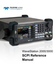
All digital scopes use the basic block diagram shown <strong>in</strong> Figure 1. The<br />
<strong>in</strong>put signal passes through an amplifier/attenuator stage, then an ADC<br />
converts the time vary<strong>in</strong>g signal amplitude to a series of numbers which<br />
are stored <strong>in</strong> memory. The digital data from the acquisition memory is<br />
sent to a microprocessor.<br />
Figure 1 Block Diagram of a generic DSO<br />
The Analog<br />
Signal Path<br />
Construct<strong>in</strong>g a 6 GHz path that can digitize signals <strong>in</strong> real time requires<br />
both careful design and specialized technology. In fact only <strong>LeCroy</strong> has<br />
a full speed path that can track an <strong>in</strong>com<strong>in</strong>g signal with a 6 GHz<br />
bandwidth amplifier/attenuator, digitize it and transfer the data <strong>in</strong> real<br />
time <strong>in</strong>to long memory.<br />
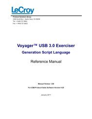
Figure 1 shows the average frequency response (Bode plot) of 100<br />
WaveMaster series 6 GHz scopes. <strong>LeCroy</strong> tests the bandwidth every unit<br />
us<strong>in</strong>g NIST traceable measurements and archives the data. The response<br />
is flat <strong>in</strong> the pass band and rolls off sharply beyond the rated bandwidth<br />
(see Figure 2). At 7 GHz, the response is down by more than 10 dB. This<br />
elim<strong>in</strong>ates out-of-band noise, enabl<strong>in</strong>g the most precise tim<strong>in</strong>g and jitter
3<br />
1<br />
0 1000 2000 3000 4000 5000 6000 7000 8000 9000<br />
-1<br />
-3<br />
-5<br />
-7<br />
Series1<br />
Series2<br />
Series3<br />
-9<br />
-11<br />
-13<br />
-15<br />
Figure 2 This Bode plot shows the average response of one hundred 6 GHz<br />
WaveMasters. Response is very flat <strong>in</strong> the pass band, and rolls off quickly<br />
above 6 GHz to preserve a low noise floor.<br />
measurements. This rolloff is made possible by advanced digital<br />
filter<strong>in</strong>g techniques , the subject of several patent applications.<br />
The 6GHz signal path is made possible by 3 Silicon Germanium<br />
Integrated Circuits designed by <strong>LeCroy</strong> and fabricated by IBM:<br />
• The MFE441, an amplifier/attenuator, with >6 GHz bandwidth.<br />
This drives up to 2 ADC’s (for channel <strong>in</strong>terleav<strong>in</strong>g) and the Trigger<br />
System.<br />
• The MAD440 ADC with >6 GHz bandwidth and 10 GS/s maximum<br />
sample rate per chip.<br />
• The MTT trigger chip with >5 GHz bandwidth, provid<strong>in</strong>g the<br />
world’s fastest real time scope trigger.<br />
This chipset provides capabilities unmatched by any other oscilloscope.<br />
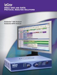
In addition (see Figure 3) the signal path conta<strong>in</strong>s:<br />
• A front panel connector whose core conductor is rated at 18 GHz.<br />
• A 12GHz relay which switches a x1 or x10 attenuator <strong>in</strong>to the signal
Adjacent Channel<br />
Probu<br />
s<br />
Input<br />
Channel<br />
50 ohm<br />
20 dB<br />
atten<br />
50 2.5V ohms<br />
Precision<br />
Reference<br />
Cal<br />
DAC<br />
Offset<br />
DAC<br />
MFE44<br />
1<br />
Offset<br />
MAD440<br />
18 bit<br />
data<br />
Clock<br />
18 bit<br />
data<br />
18 bit<br />
data<br />
Clock<br />
JTAG<br />
MAM439<br />
MAM439<br />
MAM43<br />
9<br />
62.5<br />
MHz<br />
8b/10b<br />
data<br />
Transceiver<br />
1.25 Gbits/s<br />
125 MHz<br />
8b/10b<br />
data<br />
1.25 Gbits/s<br />
serial data<br />
Antonomous Acquisition Control<br />
and Timebase<br />
Figure 3 A WaveMaster front end. Simplicity is the key to obta<strong>in</strong><strong>in</strong>g a<br />
low noise, high bandwidth signal path. The MFE (monolithic Front End)<br />
and MAD (monolithic analog to digital converter) are both SiGe. The<br />
acquisition memory (MAM) is built us<strong>in</strong>g a high speed CMOS process.<br />
Digitiz<strong>in</strong>g the Data<br />
After amplification and condition<strong>in</strong>g, the now-differential signal is<br />
passed to the ADC. S<strong>in</strong>ce normal PC board material has significant<br />
losses at 5 GHz, the WaveMaster uses a special Rogers 4003 low<br />
dielectric constant material. These traces have 0.18 dB loss per <strong>in</strong>ch at<br />
10 GHz. The ADC converts the signal <strong>in</strong>to eight bit data, mak<strong>in</strong>g one<br />
measurement every 100 picoseconds. The data bits are sent via six data<br />
ports to three <strong>LeCroy</strong>-designed embedded DRAM’s. These high-speed<br />
CMOS chips can each accept data at a rate of 3.3333 gigabytes per<br />
second (total aggregate of 10 Gbytes/sec), mak<strong>in</strong>g them possibly the<br />
world’s fastest DRAM’s. No other scope has technology capable of<br />
captur<strong>in</strong>g data at 10 Gbytes per second (20 Gbytes/sec when us<strong>in</strong>g two<br />
channels) <strong>in</strong>to long memory. This technology is key to ma<strong>in</strong>ta<strong>in</strong><strong>in</strong>g high<br />
sample rate, thereby preserv<strong>in</strong>g signal <strong>in</strong>tegrity.
DSP <strong>in</strong> the<br />
Digital <strong>Oscilloscope</strong><br />
The oscilloscope has evolved <strong>in</strong>to the most valuable tool utilized <strong>in</strong> the<br />
development of all forms of electronics equipment. This evolution is<br />
supported by many radical technology changes . These enable a DSO to<br />
reach previously-impossible performance <strong>in</strong> bandwidth, sample rate,<br />
memory length and signal fidelity. Critical technology enablers have<br />
<strong>in</strong>cluded Silicon Germanium (SiGe), high-speed DRAM and high-speed<br />
processors. These technologies have been exploited by high-end scope<br />
manufacturers at the earliest opportunity.<br />
In oscilloscopes, the primary need is to acquire complex, high-speed<br />
waveforms with high precision and to make accurate measurements of<br />
these waveforms. The aforementioned technologies have produced huge<br />
advances <strong>in</strong> the speed and duration of signal acquisition. <strong>LeCroy</strong> has<br />
focused on these capabilities, together with throughput—the speed at<br />
which waveforms can be processed. The convergence of speed,<br />
duration, and throughput enables <strong>LeCroy</strong> to acquire and analyze waveforms<br />
faster and more accurately than any other manufacturer. <strong>LeCroy</strong><br />
has comb<strong>in</strong>ed these capabilities to provide real-time digital signal<br />
process<strong>in</strong>g <strong>in</strong> it’s WaveMaster oscilloscopes<br />
<strong>LeCroy</strong> has long recognized that together with the “banner” specifications,<br />
analog signal fidelity is of utmost importance. <strong>LeCroy</strong> uses its<br />
DSP technology to deliver higher signal fidelity than that achievable <strong>in</strong><br />
hardware alone.<br />
DSP is not a new concept. Its orig<strong>in</strong>s lie as far back as the French<br />
mathematician Fourier. The bulk of the advancements that form the<br />
theoretical basis for its widespread use were made circa 1960. Decades<br />
ago, DSP was utilized only <strong>in</strong> military and <strong>in</strong>telligence applications that<br />
could afford the most powerful computers. Advanced DSP was<br />
impractical for most applications due to the extreme process<strong>in</strong>g power<br />
required. The arrival of the microprocessor <strong>in</strong> the early 1970s began a<br />
revolution that cont<strong>in</strong>ues to unlock the power of DSP for everyday<br />
applications. We have seen DSP permeate every aspect of everyday life,<br />
as evidenced by the follow<strong>in</strong>g table:<br />
Application Pre-DSP DSP-enabled<br />
Audio Record<strong>in</strong>g Analog Tape CD, MP3<br />
Cellular Phones Analog GSM, CDMA, UMTS<br />
Video Record<strong>in</strong>g VHS Tape DVD<br />
Television NTSC, PAL, Secam HDTV, DSB
DSP has been utilized sporadically <strong>in</strong> digital oscilloscopes, for example,<br />
the application of a s<strong>in</strong>e x/x filter to <strong>in</strong>terpolate the signal position <strong>in</strong><br />
between ADC samples is one type of common DSP. But its full potential<br />
went untapped as the cost of dedicated DSP processors made them<br />
impractical. Recent developments <strong>in</strong> processor performance, however,<br />
are creat<strong>in</strong>g a technology shift toward DSP <strong>in</strong> the oscilloscope bus<strong>in</strong>ess.<br />
Like previous technology shifts (vacuum tubes to semiconductors,<br />
analog CRT’s to digital oscilloscopes) these advances will be adopted at<br />
different rates by different vendors. But the advantages they provide<br />
make their ultimate adoption <strong>in</strong>evitable.<br />
DSP is not magic, trickery, or a technique used to fool people. It has its<br />
roots <strong>in</strong> the mathematics of l<strong>in</strong>ear systems, differential equations, and<br />
the LaPlace and Fourier transforms. <strong>LeCroy</strong> uses DSP to improve signal<br />
fidelity beyond that provided by the raw hardware. This does not mean<br />
that <strong>LeCroy</strong> extends its scopes’ bandwidth through DSP. If signals are<br />
not passed to the ADC at full bandwidth, no amount of DSP will cause<br />
miss<strong>in</strong>g details to reappear. But <strong>LeCroy</strong>’s comb<strong>in</strong>ation of 6 GHz signal<br />
acquisition AND advanced DSP provides benefits <strong>in</strong> the areas of<br />
flatness, phase response, and the removal of digitization artifacts. We<br />
will address these three areas <strong>in</strong> detail.<br />
Due to imperfections <strong>in</strong> hardware components, no oscilloscope has a<br />
perfectly flat analog frequency response. At very high frequencies,<br />
transmission l<strong>in</strong>e effects make the job of provid<strong>in</strong>g a flat response very<br />
difficult. Previous compensation techniques <strong>in</strong>volved tunable filters and<br />
components, usually employ<strong>in</strong>g trims or component selection. More<br />
recent techniques employ laser trimm<strong>in</strong>g of component characteristics<br />
either on the circuit board, hybrid, or the chip die itself. All oscilloscope<br />
manufacturers use some comb<strong>in</strong>ation of these elements to enhance the<br />
flatness of their <strong>in</strong>struments. <strong>LeCroy</strong> uses a comb<strong>in</strong>ation of on-die<br />
variable bandwidth adjustments and DSP filters to make the f<strong>in</strong>al flatness<br />
adjustments. This hardware/DSP comb<strong>in</strong>ation replaces multiple<br />
hardware adjustments, and performs better than hardware only techniques.<br />
The result is enhanced signal <strong>in</strong>tegrity.<br />
<strong>LeCroy</strong> Wavemaster 8600A oscilloscopes enter<strong>in</strong>g the adjustment phase<br />
of the manufactur<strong>in</strong>g process have bandwidth <strong>in</strong> excess of 6 GHz. Ondie<br />
variable bandwidth adjustments and custom digital filters then br<strong>in</strong>g<br />
them to the desired flatness. The bandwidth adjustment filters are also<br />
used to reduce alias<strong>in</strong>g when lower sample rates are employed. The<br />
phase response of the scope is l<strong>in</strong>earized through the use of digital filters<br />
to provide nearly constant group-delay characteristics.
F<strong>in</strong>ally, digital filters are employed to tailor the frequency response to<br />
an approximate fourth order Bessel filter, with noise reduction filters<br />
<strong>in</strong>troduced at around 6.5 GHz. These filters remove quantization noise<br />
which is an artifact of the digitization process.<br />
It is <strong>in</strong>terest<strong>in</strong>g to note that all of the DSP techniques utilized <strong>in</strong> the<br />
WaveMaster were orig<strong>in</strong>ally developed for analog circuit design. These<br />
transfer functions would previously have been implemented with<br />
<strong>in</strong>ductors, resistors and capacitors, and have simply been adapted for<br />
digital implementation which is more precise and repeatable than older<br />
analog methods.<br />
Typical filters utilized with<strong>in</strong> the WaveMaster DSO are 30 pole/zero IIR<br />
filters, calculated dynamically as required. The calculation of these<br />
filters is extremely complex and the ref<strong>in</strong>ement of this technology is the<br />
result of many years of <strong>in</strong>vestment <strong>in</strong>to DSP technology. Because of the<br />
seamless <strong>in</strong>tegration of its acquisition system with the W<strong>in</strong>tel platform,<br />
<strong>LeCroy</strong> is able to digitally process the raw acquired data at a rate of one<br />
GFLOP (one billion float<strong>in</strong>g po<strong>in</strong>t operations per second).<br />
In summary, <strong>LeCroy</strong> has produced a DSO whose unmatched process<strong>in</strong>g<br />
performance enables the use of DSP to enhance signal fidelity. <strong>LeCroy</strong><br />
has long demonstrated a stand<strong>in</strong>g commitment to deliver the highest<br />
<strong>in</strong>tegrity measurement <strong>in</strong>struments available. The application of DSP<br />
technology to the DSOs is not an accident, but an example of that<br />
commitment. The result is faster and more accurate views and measurements<br />
of signals.<br />
Customer and<br />
Product Support<br />
A comparison of the technical specifications of digital oscilloscope<br />
<strong>in</strong>struments is one way of determ<strong>in</strong><strong>in</strong>g value. A more complete comparison<br />
encompasses the overall experience a customer will have as a<br />
user of a particular piece of <strong>in</strong>strumentation. Factors such as an easy to<br />
use user <strong>in</strong>terface, knowledgeable assistance, applications expertise and<br />
long term product support are all key aspects of the user’s experience.<br />
<strong>LeCroy</strong> prides itself on its commitment to service the products we sell,<br />
long after we have stopped manufactur<strong>in</strong>g them. Our policy is to support<br />
(repair and calibrate) our <strong>in</strong>struments 7 years after we discont<strong>in</strong>ue a<br />
product from general availability. We stand alone <strong>in</strong> the <strong>in</strong>dustry with<br />
this policy. This was not always the case; our primary competitors had<br />
these same customer support commitments at one time. Some have<br />
recently reduced their long-term product support, limit<strong>in</strong>g the useful life<br />
of their <strong>in</strong>struments. The profits result<strong>in</strong>g from these decisions have<br />
come at the direct expense of their customers.
Similarly, the <strong>in</strong>dustry-standard oscilloscope warranty is 3 years.<br />
<strong>LeCroy</strong> ma<strong>in</strong>ta<strong>in</strong>s its 3-year warranties despite recent moves by others<br />
<strong>in</strong> the <strong>in</strong>dustry to shorten warranties and reduce long-term support.<br />
<strong>LeCroy</strong>’s direct and highly technical sales and applications eng<strong>in</strong>eer<strong>in</strong>g<br />
team are available on-site and around the world to assist our customers<br />
<strong>in</strong> gett<strong>in</strong>g the most out of our <strong>in</strong>struments. Unlike our competition, we<br />
have a s<strong>in</strong>gular focus on digital storage oscilloscopes. Our sales<br />
eng<strong>in</strong>eers devote all of their tra<strong>in</strong><strong>in</strong>g efforts to these products, and are<br />
undistracted by widely diverse product l<strong>in</strong>es. <strong>LeCroy</strong> sales and<br />
applications eng<strong>in</strong>eers “majored” <strong>in</strong> digital oscilloscope applications<br />
and their knowledge runs deep. Count on them to help you through your<br />
measurement applications.<br />
F<strong>in</strong>ally, we strive to ensure that <strong>LeCroy</strong> products can always be upgraded.<br />
When you purchase an <strong>in</strong>strument from <strong>LeCroy</strong>, you are assured<br />
of the ability to add any of the orig<strong>in</strong>al options at any time, typically for<br />
the same price you would have paid at time of purchase. <strong>LeCroy</strong> always<br />
endeavors to make new features retrofittable <strong>in</strong>to previous designs. This<br />
means that as <strong>LeCroy</strong> <strong>in</strong>novations are <strong>in</strong>troduced, you can order them<br />
for your exist<strong>in</strong>g <strong>LeCroy</strong> scope, mak<strong>in</strong>g it virtually obsolescence proof.<br />
Even the acquisition memory and process<strong>in</strong>g RAM <strong>in</strong> most oscilloscopes<br />
can be upgraded.<br />
<strong>LeCroy</strong> is proud of its 38 year heritage and devotion to signal fidelity,<br />
and customer support.