Pressure Transducer xxx bar 0/4-20mA
Pressure Transducer xxx bar 0/4-20mA
Pressure Transducer xxx bar 0/4-20mA

Create successful ePaper yourself
Turn your PDF publications into a flip-book with our unique Google optimized e-Paper software.
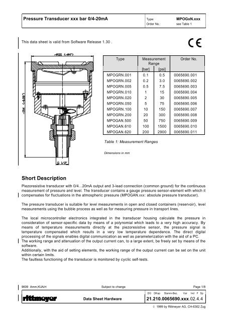
<strong>Pressure</strong> <strong>Transducer</strong> <strong>xxx</strong> <strong>bar</strong> 0/4-<strong>20mA</strong> Type: MPOGxN.<strong>xxx</strong><br />
This data sheet is valid from Software Release 1.30 .<br />
Short Description<br />
Type Measurement<br />
Range<br />
MPOGRN.001<br />
MPOGRN.002<br />
MPOGRN.005<br />
MPOGRN.010<br />
MPOGRN.020<br />
MPOGRN.050<br />
MPOGRN.100<br />
MPOGRN.200<br />
MPOGAN.500<br />
MPOGAN.610<br />
MPOGAN.620<br />
Order No.: see Table 1<br />
[<strong>bar</strong>] [psi]<br />
0.1<br />
0.2<br />
0.5<br />
1<br />
2<br />
5<br />
10<br />
20<br />
50<br />
100<br />
200<br />
Table 1: Measurement Ranges<br />
Dimensions in mm<br />
0.5<br />
3.0<br />
7.5<br />
15<br />
30<br />
75<br />
150<br />
300<br />
750<br />
1500<br />
2900<br />
Order No.<br />
0065690.001<br />
0065690.002<br />
0065690.003<br />
0065690.004<br />
0065690.005<br />
0065690.006<br />
0065690.007<br />
0065690.008<br />
0065690.009<br />
0065690.010<br />
0065690.011<br />
Piezoresistive transducer with 0/4...<strong>20mA</strong> output and 3-lead connection (common ground) for the continuous<br />
measurement of pressure and level. The transducer contains a gauge pressure sensor-element with which it<br />
compensates for fluctuations in the atmospheric pressure (MPOGAN.<strong>xxx</strong>: absolute pressure transducer).<br />
The pressure transducer is suitable for level measurements in open and closed containers (reservoir), level<br />
measurements using the bubble process as well as for measuring pressure in transport lines.<br />
The local microcontroller electronics integrated in the transducer housing calculate the pressure in<br />
consideration of sensor-specific data by means of a polynomial which leads to a very high accuracy. By<br />
means of temperature measurements directly at the piezoresistive sensor, the pressure signal is<br />
temperature compensated which results in a very low temperature dependence. The direct digital<br />
processing of the signals enables digital communication as well as parameterization with the aid of a PC.<br />
The working range and attenuation of the output current can, to a large extent, be freely set by means of the<br />
software.<br />
Additionally, with the aid of setting elements, the working range of the output current can be set on the unit<br />
within certain limits.<br />
The faultless functioning of the transducer is monitored by cyclic self-tests.<br />
9609 Amm,KUA/rt Subject to change Page 1/8<br />
DG DKap Stamm-Bez. Var Ind F Sp<br />
Data Sheet Hardware 21.210.0065690.<strong>xxx</strong>.02.4.4<br />
© 1999 by Rittmeyer AG, CH-6302 Zug
<strong>Pressure</strong> <strong>Transducer</strong> <strong>xxx</strong> <strong>bar</strong> 0/4-<strong>20mA</strong> MPOGxN.<strong>xxx</strong><br />
Technical Data<br />
Type: MOGxN. 001 002 005 010 020 050 100 200 500 610 620<br />
Measurement range<br />
1) (FS) (pre-pressure) [<strong>bar</strong>]<br />
[psi]<br />
0.1<br />
1.5<br />
0.2<br />
3<br />
0.5<br />
7.5<br />
Overload [<strong>bar</strong>] 2.5 2.5 3 4 7 15 30 60 150 250 500<br />
Measurement range negative<br />
2)<br />
1<br />
15<br />
2<br />
30<br />
[<strong>bar</strong>] -0.1 -0.2 -0.5 -1 -1 -1 -1 -1 --- --- ---<br />
Linearity, Hysteresis [ FS] ≤ 0.25 ≤ 0.15 ≤ 0.15 ≤ 0.15 ≤ 0.15 ≤ 0.15 ≤ 0.15 ≤ 0.15 ≤ 0.15 ≤ 0.15 ≤ 0.15<br />
and reproducibility -20…+70 °C<br />
(-4…158°F)<br />
Thermal Hysteresis [% FS] ≤ 0.4 ≤ 0.2 ≤ 0.1 ≤ 0.1 ≤ 0.1 ≤ 0.1 ≤ 0.1 ≤ 0.1 ≤ 0.1 ≤ 0.1 ≤ 0.1<br />
Long-term stability typ. [% FS/a] 0.2 0.1 0.1 0.1 0.1 0.1 0.1 0.1 0.1 0.1 0.1<br />
Temperature influence<br />
(T cal = 25 °C or 77°F)<br />
typ. [ppm/°C FS]<br />
max. [ppm/°C FS]<br />
100<br />
150<br />
60<br />
100<br />
60<br />
100<br />
1) An overpressure of +20% of the respective measurement range end value in [<strong>bar</strong>] is permissible. An additional linearity and Hysteresis<br />
error of max 0.2% FS or max. 0.4% FS with 0.1<strong>bar</strong> type must however be taken into consideration.<br />
2) If the transducer is exposed to negative pressure, an additional linearity and Hysteresis error of max. 0.5% FS must be taken into<br />
consideration.<br />
Note: On exceeding 120% of the nominal measurement range in [<strong>bar</strong>] or on falling below the permissible negative pressure, the<br />
output current amounts to 0mA, independent of the current range selection.<br />
Measurement Range Independent Technical Data<br />
• Output current: 0 ... 20 or 4 ... <strong>20mA</strong><br />
• Resolution of D/A conversion: 12 Bit (related to the measuring range entered)<br />
• Measuring rate: 4 pressure measurements per second<br />
• progr. attenuation (damping) of current output: 0 … 600s<br />
• SW-Rangeability of zero point and span: as desired<br />
• HW-Rangeability of zero point: -5 ... +5% of nominal measurement range (FS)<br />
• HW-Rangeability of measuring span: 95 ... 105% of nominal measurement range<br />
(FS)<br />
• Power supply: DC 9.6 ... 28.8V (DC 12 ... 24V ±20%)<br />
• Current consumption (-20°C...+70°C or -4°F...+158°F): approx. 14mA + Iout ≤ 36mA<br />
• Resistance load of extension cable MPZVK3: 75mΩ/m (0.5mm2)<br />
• Permissible load in current output: Rout[Ω] ≤ (Usonde[V] - 4.6[V]) / 0.02[A]<br />
• Permissible load in power supply: Rsup[Ω] ≤ (Usup[V] - 9.6[V]) / 0.036[A]<br />
• Overvoltage protection: *) Integrated fine protection for supply and signal<br />
circuits for transients of up to 500V<br />
• Reverse polarity protection: Integrated reverse battery protection for supply<br />
and signal circuits for voltages up to -28.8V<br />
• Protection class: IP65 (NEMA 4)<br />
• Operating temperature range: -20oC ... +70oC ( -4°F … +158°F)<br />
• Storage temperature range: -30oC ... +80oC (-22°F … +176°F)<br />
• Humidity: 0 ... 95% rel. humidity<br />
• Weight of pressure transducer without cable: approx. 850g, 1.87 pounds<br />
• Feeder clamps: 3 terminal screws for wire cross-sections of up<br />
to 1.5mm2<br />
• Cable coupling: PG11 glands<br />
• Threaded connection: Gc ½" (conical), with turning adaptation SW36<br />
*) For field use with connection cables ≥ 5m in length or ≥ 100m within a building, the optional three-core overvoltage protection MPZOGU<br />
must be used.<br />
9609 Amm,KUA/rt Subject to change Page 2/8<br />
60<br />
100<br />
60<br />
100<br />
5<br />
75<br />
60<br />
100<br />
10<br />
150<br />
60<br />
100<br />
20<br />
300<br />
60<br />
100<br />
50<br />
750<br />
60<br />
100<br />
100<br />
1500<br />
60<br />
100<br />
200<br />
3000<br />
60<br />
100<br />
DG DKap Stamm-Bez. Var Ind F Sp<br />
Data Sheet Hardware 21.210.0065690.<strong>xxx</strong>.02.4.4<br />
© 1999 by Rittmeyer AG, CH-6302 Zug
<strong>Pressure</strong> <strong>Transducer</strong> <strong>xxx</strong> <strong>bar</strong> 0/4-<strong>20mA</strong> MPOGxN.<strong>xxx</strong><br />
Quality Tests<br />
CE-conformity to the EMC terms of reference of EU (89/336/EWG)<br />
The unit meets all requirements for the CE-identification in accordance with:<br />
• EN 50081-1: 1992<br />
• EN 50082-2: 1995<br />
(see also conformity statement 21.281.0012000.001 and conformity evidence 21.280.0012000.001)<br />
Additional EMC tests<br />
• Surge ENV 50142, EN 61000-4-5 (IEC 1000-4-5): Test level 3 (2 kV)<br />
(together with internal overvoltage protection<br />
MPZOGU)<br />
(see also conformity evidence 21.280.0012000.001)<br />
Insulation tests in accordance with IEC 255-5 (without overvoltage protection<br />
MPZOGU)<br />
• Pulse withstandability test: Test level 3 (2 kV)<br />
• Dielectric strength: Test level 4 (AC 1000V, 50Hz, 1 Min.)<br />
• Insulation resistance: Test level 4 (≥ 100 MΩ)<br />
ClimaticTest<br />
Climatic test in accordance with IEC 68-2-38 fulfilled.<br />
Construction of <strong>Pressure</strong> <strong>Transducer</strong><br />
The housing material consists of aluminium, the surface is anodized, the colour green-blue (RAL 5021).<br />
The parts which come into contact with the medium as well as the pressure transmitting separating<br />
membrane consist of corrosion-resistant steel 1.4435 (316L). The screwed connection itself consists of<br />
steel 1.4436 (316).<br />
On use in water, waste water, etc, with a freezing point of 0 o C, the operating temperature is limited to 0 ...<br />
+70 o C (possible damage to the separating membrane by ice formation).<br />
Electrical Connections<br />
(See conformity evidence 21.280.0012000.001 for further information about wiring)<br />
Terminal screw<br />
Earth connection<br />
Cable glands<br />
9609 Amm,KUA/rt Subject to change Page 3/8<br />
DG DKap Stamm-Bez. Var Ind F Sp<br />
Data Sheet Hardware 21.210.0065690.<strong>xxx</strong>.02.4.4<br />
© 1999 by Rittmeyer AG, CH-6302 Zug
<strong>Pressure</strong> <strong>Transducer</strong> <strong>xxx</strong> <strong>bar</strong> 0/4-<strong>20mA</strong> MPOGxN.<strong>xxx</strong><br />
Permissible Load<br />
Rout: permissible load in current output (connection Iout)<br />
Usonde: supply voltage on the pressure transducer (connection +V)<br />
Rout[Ω] ≤ (Usonde[V] - 4.6[V]) / 0.02[A]<br />
Rsup: permissible load in the power supply<br />
Usup: supply voltage<br />
Rsup[Ω] ≤ (Usup[V] - 9.6[V]) / 0.036[A]<br />
Parameterization<br />
R[ Ω]<br />
1210<br />
530<br />
250<br />
Rout<br />
Rsup<br />
0 9.6 28.8<br />
U[V]<br />
The pressure sensor can either be parameterized by the software or, after removing the housing cover, the<br />
range of the output current can be set within certain limits by means of a slide switch and the zero point and<br />
the measuring span by means of two trimmers .<br />
Parameterization by software<br />
Note: The following software parameterization can be undertaken with the help a MPO-PC adaptation<br />
MPZPCA and the corresponding MS-DOS based computer software (MPZPCS).<br />
(see also data sheet 21.210.0065693.001 and operation manual 21.810.0065707.001).<br />
In order to undertake software settings, switch S2 (SW/HW) must be in the base setting off (SW) position<br />
(see also under hardware setting possibilities).<br />
• Range selection of the output current 0 ... <strong>20mA</strong> or 4 ... <strong>20mA</strong><br />
Note: With the range selection 4 ... <strong>20mA</strong>, the output, also in the range of ≥1 ... ≤4mA is controlled<br />
proportionally to the zero point and measuring span settings. Thereby negative pressure for<br />
example can also be measured.<br />
The output can be selected up to approx. 20.5mA.<br />
In the event of failure of the pressure sensor or within the first 5 seconds after applying the<br />
supply voltage, the output current amounts to 0mA.<br />
Output current Iout<br />
Imax<br />
Imin<br />
Working range of<br />
current output<br />
Inverted control<br />
Imax typ. 20.5mA<br />
Imin = 1mA at 4...<strong>20mA</strong><br />
Imin = 0mA at 0...<strong>20mA</strong><br />
Measurement value p<br />
9609 Amm,KUA/rt Subject to change Page 4/8<br />
DG DKap Stamm-Bez. Var Ind F Sp<br />
Data Sheet Hardware 21.210.0065690.<strong>xxx</strong>.02.4.4<br />
© 1999 by Rittmeyer AG, CH-6302 Zug
<strong>Pressure</strong> <strong>Transducer</strong> <strong>xxx</strong> <strong>bar</strong> 0/4-<strong>20mA</strong> MPOGxN.<strong>xxx</strong><br />
• Rangeability of zero point and span<br />
Setting range: as desired<br />
Note: With the setting zero point > measuring span, a reversal of the output function can be<br />
achieved. Rising pressure thereby produces falling output current.<br />
• Programmable attenuation (current damping) of current output<br />
(Together with MPZPCS from Software Release 1.30)<br />
The analog output can be attenuated with a low-pass filter of 1st order in the range of 0 … 600s.<br />
Hint: Select a damping of zero during start-up.<br />
Example for setting the working range:<br />
<strong>Pressure</strong> transducer MPOGRN.010, nominal measurement range (FS) 1<strong>bar</strong><br />
Desired working range: 4mA @<br />
PA=0.25<strong>bar</strong><br />
<strong>20mA</strong> @<br />
PE=0.85<strong>bar</strong><br />
Necessary settings:<br />
Current range: 4 ... <strong>20mA</strong><br />
Zero point: 0.25<strong>bar</strong><br />
Measuring range: 0.85<strong>bar</strong><br />
Iout<br />
[mA]<br />
20.5<br />
20<br />
• Recalibration 0% and 100% of the pressure transducer<br />
Setting range 0%: -5% ... +5% of nominal measurement range (FS)<br />
Setting range 100%: 95% ... 105% of nominal measurement range (FS)<br />
4<br />
1<br />
0<br />
0.25<br />
P A<br />
Iout<br />
0.85<br />
P E<br />
1<br />
P FS<br />
p [<strong>bar</strong>]<br />
Note: The pressure transducer is calibrated to the nominal measurement range (FS) ex works. On<br />
detection of an unmistakable long-term drift, the pressure sensor should preferably be<br />
returned to the factory for recalibration. A recalibration should only be carried out locally<br />
when a corresponding reference unit is available.<br />
Hardware Setting Possibilities<br />
In order to carry out hardware settings at the unit, switch S2 (SW/HW) must be in the on (HW) position. In<br />
position off (SW) the settings for S1 (0/4mA) and 0% (zero point), 100% (measuring range) are ineffective.<br />
• Range selection for the output current 0 ... <strong>20mA</strong> or 4 ... <strong>20mA</strong><br />
S1 (0/4mA) = off: 0 ... <strong>20mA</strong><br />
S1 (0/4mA) = on: 4 ... <strong>20mA</strong><br />
Note: See also the note regarding range selection with software parameterization.<br />
9609 Amm,KUA/rt Subject to change Page 5/8<br />
DG DKap Stamm-Bez. Var Ind F Sp<br />
Data Sheet Hardware 21.210.0065690.<strong>xxx</strong>.02.4.4<br />
© 1999 by Rittmeyer AG, CH-6302 Zug
<strong>Pressure</strong> <strong>Transducer</strong> <strong>xxx</strong> <strong>bar</strong> 0/4-<strong>20mA</strong> MPOGxN.<strong>xxx</strong><br />
• Rangeability of zero point 0% and measuring span 100%<br />
Setting range for: zero point: -5% ... +5% of nominal measurement range (FS)<br />
Measuring span: 95% ... 105% of nominal measurement range (FS)<br />
Note: Changes to the two trimmers 0% or 100% and at S1 (0/4mA) will only be effective for the<br />
duration of 3 minutes after switching S2 (SW/HW) from position off to on.<br />
On the other hand, the software settings will only be active when S2 (SW/HW) remains in<br />
the off position for at least 4 seconds.<br />
Turning trimmer 0% or 100% in clockwise direction increases the setting value.<br />
Standard Settings<br />
The pressure transducers have the following standard parameterization:<br />
• Parameterization: software, S2 (SW/HW) = off<br />
• Current range: 4 ... <strong>20mA</strong><br />
• Zero point: 0<br />
• Measuring span: nominal measurement range (FS)<br />
• Damping: 0<br />
Note: Settings other than those above for the working range set at the factory must be provided with<br />
the order.<br />
Dehumidifying the Unit<br />
In order to dehumidify the unit, the desiccator bag supplied must be clamped under the holding bracket of the<br />
housing cover after removing the packing material.<br />
According to application conditions, the desiccator bag must be checked half yearly and replaced as<br />
necessary.<br />
Accessories<br />
Abbreviation Order No.<br />
• Overvoltage protection for MPOGxN.<strong>xxx</strong> MPZOGU 00 65 698.001<br />
• Branch box complete, IP65 (IP67) (NEMA4) MPZAD.002 00 65 194.001<br />
• Branch box IP65 (NEMA4) with 2 overvolt. prot. ASBG48 MPZAD2U.002 00 65 192.001<br />
• Branch box with 2 overvolt. prot. ASBG.48, IP54 (NEMA3) MPZAD2U 00 65 196.001<br />
• Extension cable (3-wire, schielded) MPZVK3 L 04 60 503<br />
• Fixing material for wall or cabinet mounting MPZBMA 00 36 108.002<br />
• Ventilation complete MPZLU 00 65 450.001<br />
• Desiccator bag 00 29 201.003<br />
• MPO Interface to PC MPZPCA 00 65 693.001<br />
(incl. MPO parameterization software MS-DOS) MPZPCS<br />
9609 Amm,KUA/rt Subject to change Page 6/8<br />
DG DKap Stamm-Bez. Var Ind F Sp<br />
Data Sheet Hardware 21.210.0065690.<strong>xxx</strong>.02.4.4<br />
© 1999 by Rittmeyer AG, CH-6302 Zug
<strong>Pressure</strong> <strong>Transducer</strong> <strong>xxx</strong> <strong>bar</strong> 0/4-<strong>20mA</strong> MPOGxN.<strong>xxx</strong><br />
Note on Pneumatic Level Measurement<br />
The regulations for pneumatic measurement in the project handbook D 48 62 100 must be observed as well<br />
as the standard solution for compressed air supply with compressors D 48 39 300.<br />
Standard Schematic<br />
MPOGxN.<strong>xxx</strong><br />
MPZOGU<br />
optional<br />
P<br />
#<br />
1, 4<br />
0V<br />
0V<br />
+V<br />
SB IF<br />
μ C<br />
3 2<br />
Iout<br />
+V Iout<br />
#<br />
9609 Amm,KUA/rt Subject to change Page 7/8<br />
∩<br />
DG DKap Stamm-Bez. Var Ind F Sp<br />
Data Sheet Hardware 21.210.0065690.<strong>xxx</strong>.02.4.4<br />
© 1999 by Rittmeyer AG, CH-6302 Zug