Future Technology Devices International Ltd FT4232H Quad High ...
Future Technology Devices International Ltd FT4232H Quad High ...
Future Technology Devices International Ltd FT4232H Quad High ...

You also want an ePaper? Increase the reach of your titles
YUMPU automatically turns print PDFs into web optimized ePapers that Google loves.
4.3.3 RS485 Configuration<br />
Document No.: FT_000060<br />
<strong>FT4232H</strong> QUAD HIGH SPEED USB TO MULTIPURPOSE UART/MPSSE IC<br />
Datasheet Version 2.09<br />
Clearance No.: FTDI#78<br />
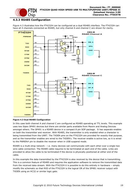
Figure 4.3 illustrates how the <strong>FT4232H</strong> can be configured as a dual RS485 interface. The <strong>FT4232H</strong> can<br />
have all 4 channels connected as RS485, but only channel A and channel C are shown for clarity.<br />
<strong>FT4232H</strong><br />
PWREN#<br />
TXD<br />
60<br />
16<br />
3<br />
4<br />
D<br />
8<br />
VCC<br />
SP481<br />
7<br />
DB9-M<br />
RS485 Channel A<br />
DM_A<br />
RXD<br />
17<br />
2<br />
6<br />
DPA<br />
RTS#<br />
18<br />
1<br />
R<br />
GND<br />
CTS#<br />
DTR#<br />
DSR#<br />
19<br />
21<br />
22<br />
5<br />
120R<br />
LINK<br />
DCD#<br />
23<br />
TXDEN<br />
TXD<br />
RXD<br />
RTS#<br />
24<br />
38<br />
39<br />
40<br />
3<br />
4<br />
2<br />
1<br />
D<br />
R<br />
8<br />
VCC<br />
SP481<br />
7<br />
6<br />
DB9-M<br />
RS485 Channel C<br />
DM_B<br />
DP_B<br />
GND<br />
CTS#<br />
DTR#<br />
DSR#<br />
41<br />
43<br />
44<br />
5<br />
120R<br />
LINK<br />
DCD#<br />
45<br />
TXDEN<br />
46<br />
Figure 4.3 Dual RS485 Configuration<br />
In this case both channel A and channel C are configured as RS485 operating at TTL levels. This example<br />
uses two Sipex SP491 devices but there are similar parts available from Maxim and Analog <strong>Devices</strong><br />
amongst others. The SP491 is a RS485 device in a compact 8 pin SOP package. It has separate enables<br />
on both the transmitter and receiver. With RS485, the transmitter is only enabled when a character is<br />
being transmitted from the UART. The TXDEN pins on the <strong>FT4232H</strong> are provided for exactly that purpose,<br />
and so the transmitter enables are wired to the TXDEN’s. The receiver enable is active low, so it is wired<br />
to the PWREN# pin to disable the receiver when in USB suspend mode.<br />
RS485 is a multi-drop network – i.e. many devices can communicate with each other over a single two<br />
wire cable connection. The RS485 cable requires to be terminated at each end of the cable. Links are<br />
provided to allow the cable to be terminated if the device is physically positioned at either end of the<br />
cable.<br />
In this example the data transmitted by the <strong>FT4232H</strong> is also received by the device that is transmitting.<br />
This is a common feature of RS485 and requires the application software to remove the transmitted data<br />
from the received data stream. With the <strong>FT4232H</strong> it is possible to do this entirely in hardware – simply<br />
modify the schematic so that RXD of the <strong>FT4232H</strong> is the logical OR of the SP481 receiver output with<br />
TXDEN using an HC32 or similar logic gate.<br />
Copyright © 2010 <strong>Future</strong> <strong>Technology</strong> <strong>Devices</strong> <strong>International</strong> Limited 19