370A and 371A Digital Storage Curve Tracers
370A and 371A Digital Storage Curve Tracers
370A and 371A Digital Storage Curve Tracers

You also want an ePaper? Increase the reach of your titles
YUMPU automatically turns print PDFs into web optimized ePapers that Google loves.
<strong>370A</strong> <strong>and</strong> <strong>371A</strong> <strong>Digital</strong><br />
<strong>Storage</strong> <strong>Curve</strong> <strong>Tracers</strong><br />
Fully Programmable <strong>Digital</strong> <strong>Curve</strong><br />
<strong>Tracers</strong> with Cursors <strong>and</strong> Hardcopy<br />
High-resolution DC Parametric Measurements<br />
with the <strong>370A</strong><br />
High Voltage <strong>and</strong> Current Sourcing<br />
with the <strong>371A</strong><br />
Metrics Software <strong>and</strong> LabView<br />
Drivers Available to Enhance Operation<br />
CE Certified<br />
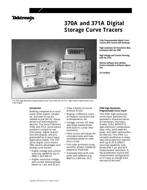
The <strong>370A</strong> High-Resolution Programmable <strong>Curve</strong> Tracer (left) <strong>and</strong> the <strong>371A</strong> High-Power Programmable <strong>Curve</strong><br />
Tracer (right).<br />
Introduction<br />
Nothing compares to a curve<br />
tracer when power, versatility,<br />
<strong>and</strong> ease of use are<br />
needed to test the DC characteristics<br />
of semiconductor<br />
devices. The Sony/Tektronix<br />
<strong>370A</strong> <strong>and</strong> <strong>371A</strong> curve tracers<br />
combine a simple-to-use<br />
front panel, digital acquisition<br />
<strong>and</strong> display, <strong>and</strong> programmability<br />
to serve many<br />
application needs. The 370-<br />
series digital curve tracers<br />
offer several advantages over<br />
analog curve tracers:<br />
• Higher voltage <strong>and</strong> current<br />
sourcing capability (up to<br />
3000 V <strong>and</strong> 400 A)<br />
• Higher resolution voltage<br />
<strong>and</strong> current measurements<br />
(down to 1 pA <strong>and</strong> 50 µV)<br />
• View a family of curves<br />
without flicker<br />
• Display a reference curve<br />
to measure variations due<br />
to temperature, etc.<br />
• Voltage, current, DC beta,<br />
<strong>and</strong> slope measurement<br />
with built-in cursor measurements<br />
• Store curves <strong>and</strong> setups for<br />
consistent tests <strong>and</strong> measurements<br />
based on reference<br />
curves<br />
• Full-color printouts using<br />
an HPGL plotter instead of<br />
expensive Polaroids<br />
• Automate tests with computer<br />
<strong>and</strong> software (e.g.,<br />
Metrics, LabView, etc.)<br />
<strong>370A</strong> High-Resolution<br />
Programmable <strong>Curve</strong> Tracer<br />
The <strong>370A</strong> high-resolution<br />
curve tracer performs DC<br />
parametric characterization<br />
of transistors, thyristors,<br />
diodes, SCRs, MOSFETs,<br />
opto-electronic components,<br />
solar cells, solid-state displays,<br />
<strong>and</strong> other semiconductor<br />
devices. The <strong>370A</strong> is a<br />
versatile workhorse in many<br />
labs <strong>and</strong> production stations<br />
with up to 20 A/2000 V<br />
sourcing capability combined<br />
with 1 pA <strong>and</strong> 50 V<br />
measurement resolution. It<br />
has pushbutton source <strong>and</strong><br />
measurement configuration<br />
so it’s easy to change from<br />
one test to the next.<br />
Copyright © 1996 Tektronix, Inc. All rights reserved.
<strong>371A</strong> High-Power Programmable<br />
<strong>Curve</strong> Tracer<br />
The <strong>371A</strong> high-power curve<br />
tracer performs DC parametric<br />
characterization on a<br />
wide variety of power semiconductors<br />
including thyristors,<br />
SCRs, IGBTs, <strong>and</strong> power<br />
MOSFETs. The high-voltage<br />
collector mode permits testing<br />
the Off-Characteristics of<br />
a device up to 3000 volts.<br />
The pulsed high-current collector<br />
mode provides output<br />
current pulses greater than<br />
400 amps peak for testing<br />
On-Characteristics. It also<br />
permits high-power testing<br />
up to 3,000 watts. In the<br />
sweep measurement mode,<br />
the <strong>371A</strong> automatically constructs<br />
a family of curves<br />
while stimulating the device<br />
with low-duty-cycle pulses.<br />
With this capability, power<br />
curves can be displayed<br />
without excessive heating of<br />
the device.<br />
Interactive, Programmable<br />
Control<br />
Interactive control of all<br />
<strong>370A</strong>/<strong>371A</strong> measurements is<br />
accomplished from the full<br />
featured front panel or over<br />
the GPIB. Every operating<br />
parameter can be controlled<br />
using a GPIB controller. For<br />
interactive control, Metrics<br />
software provides complete<br />
control <strong>and</strong> analysis without<br />
having to program the instrument.<br />
370/371-series Lab-<br />
View drivers are available<br />
from the Tektronix BBS.<br />
These drivers have many of<br />
the building blocks for creating<br />
a custom measurement<br />
solution.<br />
Store <strong>and</strong> Recall Setups <strong>and</strong><br />
Digitized <strong>Curve</strong>s<br />
Up to 64 digitized characteristic<br />
curves can be stored on<br />
a diskette <strong>and</strong> recalled at the<br />
touch of a button. A live<br />
curve can then be compared<br />
with a previously stored<br />
curve to assess temperature<br />
drift or other changes in<br />
operating parameters. To<br />
help identify the data, up to<br />
24 characters of text may be<br />
used to label or annotate the<br />
curve data.<br />
Operating parameters can be<br />
adjusted, stored, <strong>and</strong> recalled<br />
using several storage methods<br />
including the <strong>370A</strong>/<strong>371A</strong><br />
non-volatile memory, the<br />
built-in DOS compatible<br />
floppy disk, or to an external<br />
GPIB controller.<br />
Built-in Cursor Measurements<br />
The <strong>370A</strong>/<strong>371A</strong> provides<br />
three cursor-measurement<br />
modes. The Dot cursor provides<br />
direct screen readout of<br />
voltage, current, gm, or DC<br />
beta at any point. The Window<br />
cursor can be positioned<br />
between two curves to measure<br />
small-signal beta or gm,<br />
<strong>and</strong> can also be used for<br />
visual go/no-go tests. The<br />
Function Line cursor provides<br />
screen readout of a<br />
slope or intercept value.<br />
Test Fixturing<br />
A test fixture which provides<br />
safe device enclosure to<br />
ensure operator protection<br />
during measurements is provided<br />
as a st<strong>and</strong>ard accessory.<br />
The test fixture accommodates<br />
st<strong>and</strong>ard A1001<br />
through A1005 adapters with<br />
Kelvin sensing, 3-pin<br />
adapters without Kelvin<br />
sensing, <strong>and</strong> the A1023 <strong>and</strong><br />
A1024 surface-mount<br />
adapters.<br />
Direct Hardcopy<br />
Plotter output data can be<br />
sent directly from the<br />
<strong>370A</strong>/<strong>371A</strong> without the need<br />
for an external controller.<br />
Plotting can continue while<br />
the <strong>370A</strong>/<strong>371A</strong> performs the<br />
next tasks.<br />
Test <strong>and</strong> Measurement Software<br />
Metrics ICS Interactive Characterization<br />
Software (Tektronix<br />
PN 063-1649-00) combined<br />
with the 370/371<br />
driver (Tektronix PN<br />
063-1650-00) offers computer-controlled<br />
DC parameter<br />
characterization <strong>and</strong> analysis<br />
of numerous semicon-<br />
page 2
1<br />
Define<br />
Test<br />
Setup<br />
2<br />
Press the Measure<br />
Button to Capture Data<br />
3<br />
Plot the Data <strong>and</strong> Make<br />
Measurements<br />
Setup, capture, <strong>and</strong> measurement with Metrics ICS software.<br />
ductor devices. Every aspect<br />
of instrument control <strong>and</strong><br />
data analysis is available<br />
through a set of interactive<br />
dialog boxes that are configured<br />
in a graphics-oriented<br />
Microsoft Windows environment.<br />
Metrics ICS can make<br />
measurements that are not<br />
available on a manually<br />
operated instrument, including<br />
the ability to sweep any<br />
supply. Extensive data management<br />
capabilities include<br />
project files, data export,<br />
DDE links, <strong>and</strong> search capabilities.<br />
Metrics ICS built-in<br />
automation capabilities<br />
include conditional pass/fail<br />
testing <strong>and</strong> result logging.<br />
Labview Driver<br />
<strong>370A</strong> <strong>and</strong> <strong>371A</strong> drivers for<br />
National Instruments Lab-<br />
View software is available<br />
from the Tektronix Bulletin<br />
Board Service. These drivers<br />
allow setting most controls<br />
in the instrument, saving<br />
data to disk, <strong>and</strong> displaying<br />
the data on the computer<br />
screen. Since LabView is a<br />
graphical programming language,<br />
the drivers can be<br />
modified to suit a particular<br />
measurement requirement.<br />
To download either driver,<br />
set your modem for N,8,1,<br />
19,200 baud <strong>and</strong> dial<br />
503-627-5658. Once logged<br />
in, select the download<br />
option <strong>and</strong> type TEK370.ZIP<br />
to download the 370 driver<br />
or TEK371.ZIP to download<br />
the 371 driver.<br />
Labview ATEdemo incorporates many of the 370/371 control VIs.<br />
page 3
<strong>370A</strong><br />
Characteristics<br />
Collector Supply<br />
Step Generator<br />
Polarity Modes – AC, DC, Leakage, Rectified<br />
Sine.<br />
Range – 16 V, 80 V, 400 V, 2000 V.<br />
Max Peak Current – 10 A, 2 A, 0.4 A, 0.05 A.<br />
Peak Current Pulsed – 20 A, 4 A, 0.8 A, 0.1 A .<br />
Minimum Series Resistance – 0.26 Ω,<br />
6.4 Ω, 160 Ω, 20 kΩ.<br />
Maximum Series Resistance – 800 Ω,<br />
20kΩ, 500kΩ, 12.5MΩ.<br />
Peak Power Wattage – 0.08W, 0.4W, 2W,<br />
10W, 50W, 220W.<br />
Current Mode –<br />
Amplitude range: 50 nA to 200 mA in 1-2-5<br />
sequence in 21 steps.<br />
Maximum current: 20X STEP AMPLITUDE,<br />
except for 2 A with switch set to 200 mA.<br />
Maximum voltage: At least 10 V.<br />
Maximum opposing offset current: 10X<br />
STEP AMPLITUDE.<br />
Maximum opposing volts: Less than 7 V.<br />
Ripple plus noise: Less than 0.5% X STEP<br />
AMPLITUDE + 1 nA.<br />
Voltage Mode –<br />
Amplitude switch range: 50 mV to 2 V, in<br />
1-2-5 sequence.<br />
Maximum voltage: 20 X STEP AMPLITUDE.<br />
Max current: At least 500 mA at 10 V or<br />
less, or 10 mA at 40 V.<br />
Accuracy (current or voltage steps including<br />
offset) –<br />
Incremental: 2%.<br />
Absolute: Less than 2% X total output +3%<br />
X AMPLITUDE setting.<br />
Offset Control Range – Variable from –10 to<br />
+10 X STEP AMPLITUDE, with 0.1% resolution.<br />
Short Circuit Current Limiting – 500 mA.<br />
Maximum Opposing Offset<br />
Volts – 10X STEP AMPLITUDE.<br />
Maximum Opposing Current – Less than<br />
20mA.<br />
Step Rates – 2X line frequency (1X line frequency<br />
in AC collector supply). Steps occur<br />
at 0 collector voltage.<br />
Pulsed Steps – 80 µs or 300 µs wide ±10%.<br />
Steps <strong>and</strong> Offset Polarity – Same as collector<br />
supply polarity when STEP GENERATOR<br />
POLARITY INVERT is disabled. Opposite to<br />
collector supply polarity when STEP GENER-<br />
ATOR POLARITY INVERT is selected or CON-<br />
FIGURATION is set to BASE GROUNDED,<br />
STEP GENERATOR POLARITY INVERT is disa<br />
b l e d .<br />
Number of Steps – Selectable from 0 to 10.<br />
Auxiliary Supply –<br />
Range: From –40 to +40 V with 20 mV resolution.<br />
Accuracy: Greater than 50 mV +2% of total<br />
output.<br />
Output current: ±20 V, at least 100 mA;<br />
±40V, at least 10 mA.<br />
Nonstore Mode Collector Current Range –<br />
1 A/div to 2A/div in 1-2-5 sequence of 20<br />
steps. X10 MAG extends maximum sensitivity<br />
to 100 nA/div. Both unmagnified <strong>and</strong><br />
magnified accuracy are within 3%<br />
Step Generator Display Range – 1 to 10<br />
steps/division, or 1 step/10 divisions.<br />
Unmagnified <strong>and</strong> magnified accuracy are<br />
within 3%.<br />
Display Offset – Vertical offset of display<br />
centerline value up to 10 divisions in 21<br />
half-division steps.<br />
<strong>Digital</strong> <strong>Storage</strong> Vertical Acquisitions<br />
A/D Converter –<br />
Resolution: 10 bits for 10.24 divisions, 100<br />
counts per division. Maximum data points<br />
are 1024.<br />
Maximum sampling rate: Line frequency X<br />
1024.<br />
Minimum sampling rate: Line frequency X 2.<br />
Collector Current Range – 1 A/div to<br />
2A/div in 1-2-5 sequence of 20 steps. X10<br />
MAG extends maximum sensitivity to<br />
100nA/div (1 nA resolution). Unmagnified<br />
accuracy is within 1.5% of readout +0.05<br />
div of setting with DOT cursor.<br />
Emitter Current Range – 1 nA/div to<br />
2mA/div in 1-2-5 sequence of 20 steps.<br />
X10 MAG extends maximum sensitivity to<br />
100 pA/div (1 pA resolution). Unmagnified<br />
accuracy is within 1.5% of readout<br />
+0.05div of setting + 1 nA with DOT<br />
cursor.<br />
Nonstore Horizontal Deflection System<br />
Collector Volts Range – 50 mV/div to<br />
500V/div in 1-2-5 sequence of 13 steps.<br />
X10 MAG extends maximum sensitivity to<br />
5mV/div (50 µV resolution). Unmagnified<br />
<strong>and</strong> magnified accuracy (NONSTORE) are<br />
within 3%.<br />
Base/Emitter Volts Range – 50 mV/div to<br />
5V/div in 1-2-5 sequence of 6 steps. X10<br />
MAG extends maximum sensitivity to<br />
5mV/div (50 µV resolution). Unmagnified<br />
<strong>and</strong> magnified accuracy (NONSTORE) are<br />
within 3%.<br />
Step Generator Display Range – 1 or 10<br />
steps/division, or 1 step/10 divisions.<br />
Unmagnified <strong>and</strong> magnified accuracy (NON-<br />
STORE) are within 3%.<br />
Display Offset – Horizontal offset of display<br />
center-line value up to 10 divisions in 21<br />
half-division steps.<br />
page 4
<strong>Digital</strong> <strong>Storage</strong> Horizontal Acquisition<br />
A/D Converter Acquisition –<br />
Resolution: 10 bits for 10.24 divisions, 100<br />
counts per division.<br />
Sampling rate: 2X line frequency.<br />
Collector Volts Range – 50 mV/div to<br />
500V/div in 1-2-5 sequence of 21 steps.<br />
X10 MAG extends maximum sensitivity to<br />
5mV/div (50 µV resolution). Unmagnified<br />
accuracy is within 1.5% of readout<br />
+0.03div of setting with DOT cursor.<br />
Acquisition Modes – Normal, Envelope,<br />
<strong>and</strong> Average. Envelope is Vertical or Horizontal.<br />
Average is moving average with<br />
weight of 1/16.<br />
CRT <strong>and</strong> Readout<br />
CRT – 7-inch diagonal (173 mm), electrostatic<br />
deflection, P31 phosphor.<br />
Readout – Automatic on-screen display.<br />
Over-range is shown by a flashing display.<br />
100 pA to 2 A per vertical division; 5 mV to<br />
500V per horizontal division; 5 nA to<br />
200mA <strong>and</strong> 5 mV to 2 V per step.<br />
BETA or Gm –<br />
BETA: 500 nano to 400 Mega.<br />
Gm: 50 ns to 400 s.<br />
Cursor: 4-digit horizontal <strong>and</strong> vertical values<br />
without X10 MAG: 5-digit with MAG.<br />
Offset: 4-digit value.<br />
Auxiliary supply: –40 V to +40 V.<br />
page 5
<strong>371A</strong><br />
Characteristics<br />
Collector Supply<br />
Modes (positive <strong>and</strong> negative polarities for<br />
both modes) –<br />
High Current: 250 s pulses with maximum<br />
peak of 30 V.<br />
High Voltage: Full rectified sine with maximum<br />
peak of 3000 V (positive <strong>and</strong> negative<br />
polarities for both modes).<br />
Output –<br />
High-Current (pulsed) Mode:<br />
Peak Peak Maximum<br />
Voltage Current m Power<br />
30 V +10%, –5% 400 A 3 kW<br />
30 V +10%, –5% 40 A 300 W<br />
High-Voltage Mode:<br />
Peak Peak Maximum<br />
Voltage Current m Power<br />
3 kV +10, –0% 40 mA ±20% 30 W<br />
3 kV +10, –0% 4 mA ±20% 3 W<br />
300 V +15%, –0% 4 mA ±20% 300 mW<br />
300 V +15%, –0% 0.4 mA ±20% 30 mW<br />
Polarities –<br />
NPN+: Positive.<br />
NPN–: Negative.<br />
Variable Collector Supply Range – Continuously<br />
variable from 0% to 100% in 0.1%<br />
resolution.<br />
Pulsed Collector Supply Pulse Width –<br />
250 µs 10%.<br />
Pulsed Collector Repetition Rate –<br />
3 kW: 0.25 times line frequency.<br />
300 W: 0.5 times line frequency.<br />
Loop Compensation (High Voltage mode) –<br />
Stray capacitance between collector terminal<br />
<strong>and</strong> ground is compensated for up to a<br />
maximum of 100pF.<br />
Circuit Breakers – Both the high-voltage<br />
<strong>and</strong> the high-current supplies have breakers<br />
which operate independently. The high-current<br />
output breaker opens automatically in<br />
an over-current condition. Both breakers<br />
can be operated manually.<br />
Vertical Display System Collector Current Measurement<br />
Vertical Range (in 1-2-5 increments) –<br />
3 kW maximum: 1 A/div to 50 A/div.<br />
300 W maximum: 500 µA/div to 5 A/div.<br />
30 W maximum: 100 µA/div to 500 µA/div.<br />
3 W, 300 mW maximum: 10 A/div to<br />
500A/div.<br />
30 mW maximum: 1 µA/div to 50 µA/div.<br />
Accuracy – Within 0.1 vertical division.<br />
Cursor Accuracy (nonstore mode, window<br />
cursor) – Readout X 2% plus 0.2 div of vertical<br />
setting.<br />
Horizontal Display System Collector Voltage<br />
Measurement<br />
Vertical Range (in 1-2-5 increments) –<br />
3 kW, 300 W maximum: 100 mV/div to<br />
5V/div.<br />
30 W, 3 W maximum: 50 V/div to<br />
500V/div.<br />
300 mW, 30 mW maximum: 5 V/div to<br />
50V/div<br />
Step Generator Voltage Range (VBE) –<br />
100 mV/div to 5 V/div (in increments of<br />
1-2-5).<br />
Accuracy – Within 0.1 horizontal division.<br />
Cursor Accuracy (nonstore mode, window<br />
cursor) – Readout times 2% plus 0.2 div of<br />
the horizontal setting.<br />
Step Generator<br />
Test Fixture<br />
Metrics Software<br />
Current Mode –<br />
High-Current (pulsed) Mode:<br />
Step Range Maximum Maximum<br />
<strong>and</strong> Waveform Current m Voltage<br />
1 mA/step to Step/offset 10 V<br />
2 mA/step amplitude ±20%<br />
pulsed setting X 20,<br />
maximum<br />
20 A at<br />
2A/step<br />
High-Voltage Mode:<br />
Step Range Maximum Maximum<br />
<strong>and</strong> Waveform Current m Voltage<br />
1 µA/step to Step/offset 10 V<br />
2 mA/step amplitude ±20%<br />
stairstep setting X 20,<br />
maximum<br />
20 A at<br />
2A/step<br />
Ripple, Noise – Step/offset amplitude setting<br />
X 1% plus 10 nA.<br />
Pulse Width (collector supply high-current<br />
mode, 1 mA/step step/offset amplitude setting)<br />
– 500 s ±10%.<br />
Voltage Mode –<br />
High-Current (pulsed) <strong>and</strong> High-Voltage<br />
Mode:<br />
Step Range Maximum Maximum<br />
<strong>and</strong> Waveform Current m Voltage<br />
200 mV/step to 100 mA Step/offset<br />
5 V/step +50%,–20% amplitude<br />
stairstep<br />
setting<br />
X 20,<br />
maximum<br />
50 V.<br />
Ripple, Noise – Step/offset amplitude setting<br />
X 1% plus 10 mV,<br />
Number of Steps – 0 to 10 except 0 to 5 for<br />
the 5 V/step <strong>and</strong> 2A/step ranges.<br />
Step Polarity – Same as collector supply<br />
polarity. Reverse with STEP-INVERT button.<br />
Step Rate –<br />
Pulse: 0.25 X the line frequency at 3kW,<br />
0.5 X the line frequency at 300W.<br />
Stairstep: 2 X the line frequency.<br />
Offset – 0 to 10 X the step/offset amplitude<br />
setting with 1% resolution except 0 to 5 X<br />
at 5V/step <strong>and</strong> 2A/step settings. Polarity is<br />
same as the step signal.<br />
Test Fixture – Designed to allow easy connection<br />
to a variety of devices. Includes an<br />
integral safety enclosure to assure operator<br />
protection. Special patch cords are provided<br />
for connecting large devices.<br />
Recommended Computer Configuration –<br />
Minimum processor: 386DX/33 MHz IBM<br />
compatible computer.<br />
Free memory: 8 Mb minimum.<br />
Disk space: At least 14 Mb.<br />
Floppy drive: 1.44 Mb 3.5-inch.<br />
Operating system: Microsoft Windows 3.<br />
Interface cards: National Instruments GPIB<br />
card.<br />
page 6
Ordering<br />
Information<br />
<strong>370A</strong> High Resolution <strong>Curve</strong> Tracer<br />
Includes: Operations Manual, A1001 Blank<br />
Adapter, A1005 Axial Lead Diode Adapter,<br />
A1009 Four- <strong>and</strong> Six-lead Dual-width Transistor<br />
FETAdapter, 3.5-inch Floppy Disk,<br />
Power Cord, 125 V/4 A Fuse, 250 V/2 A<br />
Fuse.<br />
<strong>370A</strong>Options<br />
Option 1R – Rackmount kit.<br />
Option 95 – Provide test report.<br />
Option 96 – Provide Inspection Passed certificate.<br />
Option C5 – Five-year calibration Service<br />
Assurance Plan.<br />
Option R2 – Two additional years repair<br />
Service Assurance Plan.<br />
International Power Plug Options<br />
Option A1 – Universal Euro 220 V, 50 Hz.<br />
Option A2 – UK 240 V, 50 Hz.<br />
Option A3 – Australian 240 V, 50 Hz.<br />
Option A4 – North American 240 V, 60 Hz.<br />
Option A5 – Switzerl<strong>and</strong> 220 V, 50 Hz.<br />
<strong>371A</strong> High Power <strong>Curve</strong> Tracer<br />
Includes: Operations Manual, Wiring Kit,<br />
A1002 In-line Adapter, A1003 TO-3/TO-66<br />
Adapter, 3.5-inch Floppy Disk, Power Cord,<br />
250 V/1 A Fuse, 250 V/2 A Fuse, 250 V/4 A<br />
Fuse.<br />
<strong>371A</strong>Options<br />
Option 1R – Rackmount kit.<br />
Option 95 – Provide test report.<br />
Option 96 – Provide Inspection Passed certificate.<br />
Option C5 – Five-year calibration Service<br />
Assurance Plan.<br />
Option R2 – Two additional years repair<br />
Service Assurance Plan.<br />
International Power Plug Options<br />
Option A1 – Universal Euro 220 V, 50 Hz.<br />
Option A2 – UK 240 V, 50 Hz.<br />
Option A3 – Australian 240 V, 50 Hz.<br />
Option A4 – North American 240 V, 60 Hz.<br />
Option A5 – Switzerl<strong>and</strong> 220 V, 50 Hz.<br />
<strong>370A</strong>/<strong>371A</strong> Optional Accessories<br />
■ Metrics Software (core program –<br />
requires 063-1650-00 drivers to operate<br />
37x curve tracers) – 063-1649-00.<br />
■ 370/371 Drivers for Metrics Software –<br />
063-1650-00.<br />
■ LabView for Windows – LVWIN.<br />
■ K475 Instrument Cart.<br />
■ HC100 Plotter for Low-cost, Four-color<br />
Plotting.<br />
■ A1001 – Blank adapter.<br />
■ A1002 – TO220 Kelvin sense adapter.<br />
■ A1003 – T03/TO066 Kelvin sense<br />
adapter.<br />
■ A1004 – Offset-lead Kelvin sense<br />
adapter.<br />
■ A1005 – Axial diode lead Kelvin sense<br />
adapter.<br />
■ A1006 – Long-lead, dual-width transistor<br />
adapter.<br />
■ A1007 – Bipolar <strong>and</strong> MOSFET transistor<br />
adapter.<br />
■ A1008 – Long-lead, dual-width, FET<br />
adapter.<br />
■ A1009 – 4- <strong>and</strong> 6-lead, dual-width FET<br />
adapter.<br />
■ A1010 – 16-pin IC, zero-insertion<br />
adapter.<br />
■ A1023 – SOT 23 for surface-mount<br />
devices.<br />
■ A1024 – TO252/SMT D-pack surfacemount<br />
devices adapter.<br />
page 7
For further information, contact Tektronix:<br />
World Wide Web: http://www.tek.com; ASEAN Countries(65) 356-3900; Australia & New Zeal<strong>and</strong>61 (2) 888-7066; Austria 43 (1) 7 0 1 7 7-261; Belgium 32 (2) 725-96-10; Brazil <strong>and</strong> South America 55 (11) 3741 8360;<br />
Canada 1 (800) 661-5625; Denmark 45 (44) 850700; Finl<strong>and</strong> 358 (9) 4783 400; France & North Africa 33 (1) 69 86 81 81; Germany, Eastern Europe, & Middle East 49 (221) 94 77-0; Hong Kong (852) 2585-6688;<br />
India 91 (80) 2275577; Italy 39 (2) 250861; Japan (Sony/Tektronix Corporation) 81 (3) 3448-4611; Mexico, Central America, & Caribbean 52 (5) 666-6333; The Netherl<strong>and</strong>s 3 12 35 6 95555; Norway 47 (22)070700;<br />
People’s Republic of China(86) 10-62351230; Republic of Korea 82 (2) 528-5299; Spain & Portugal 34 (1) 372 6000; Sweden 46 (8) 629 6500; Switzerl<strong>and</strong> 41 (42) 219192; T a i w a n 886 (2) 765-6362;<br />
United Kingdom & Eire 44 (1628) 403300; USA 1 ( 8 0 0 )4 2 6 - 2 2 0 0<br />
From other areas, contact: Tektronix, Inc. Export Sales, P.O. Box 500, M/S 50-255, Beaverton, Oregon 97077-0001, USA (503)627-1916<br />
Copyright © 1996, Tektronix, Inc. All rights reserved. Tektronix products are covered by U.S. <strong>and</strong> foreign patents, issued <strong>and</strong> pending.<br />
Information in this publication supersedes that in all previously published material. Specification <strong>and</strong> price change privileges reserved.<br />
TEKTRONIX <strong>and</strong> TEK are registered trademarks.<br />
12/96 TD/XBS 76W–10757–1