AVX/TPC Multilayer Ceramic Capacitors Catalog - RYSTON ...
AVX/TPC Multilayer Ceramic Capacitors Catalog - RYSTON ...
AVX/TPC Multilayer Ceramic Capacitors Catalog - RYSTON ...

Create successful ePaper yourself
Turn your PDF publications into a flip-book with our unique Google optimized e-Paper software.
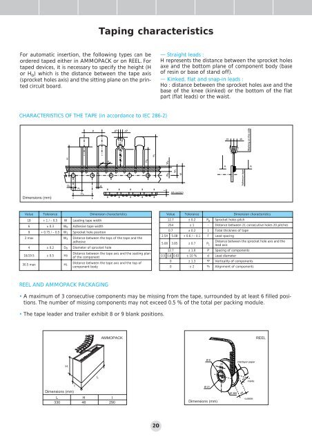
For automatic insertion, the following types can be<br />
ordered taped either in AMMOPACK or on REEL. For<br />
taped devices, it is necessary to specify the height (H<br />
or H o) which is the distance between the tape axis<br />
(sprocket holes axis) and the sitting plane on the printed<br />
circuit board.<br />
Dimensions (mm)<br />
Dimensions (mm)<br />
L H I<br />
330 46 290<br />
Taping characteristics<br />
CHARACTERISTICS OF THE TAPE (in accordance to IEC 286-2)<br />
Value Tolerance Dimension characteristics<br />
18 + 1 / – 0.5 W Leading tape width<br />
6 ± 0.3 W0 Adhesive tape width<br />
9 + 0.75 / – 0.5 W1 Sprocket hole position<br />
3 max W2 Distance between the tops of the tape and the<br />
adhesive<br />
4 ± 0.2 D0 Diameter of sprocket hole<br />
16/19.5 ± 0.5 H0<br />
Distance between the tape axis and the seating plan<br />
of the component<br />
30.5 max H1<br />
Distance between the tape axis and the top of<br />
component body<br />
REEL AND AMMOPACK PACKAGING<br />
H<br />
H<br />
D 0<br />
P 1<br />
P0<br />
P ΔP ΔP<br />
L<br />
d<br />
F H0<br />
20<br />
— Straight leads :<br />
H represents the distance between the sprocket holes<br />
axe and the bottom plane of component body (base<br />
of resin or base of stand off).<br />
— Kinked, flat and snap-in leads :<br />
Ho : distance between the sprocket holes axe and the<br />
base of the knee (kinked) or the bottom of the flat<br />
part (flat leads) or the waist.<br />
Value Tolerance Dimension characteristics<br />
12.7 ± 0.2 P0 Sprocket holes pitch<br />
254 ± 1 – Distance between 21 consecutive holes 20 pitches<br />
0.7 ± 0.2 1 Total thickness of tape<br />
2.54 5.08 + 0.6 / – 0.1 F Lead spacing<br />
5.08 3.85 ± 0.7 P1 Distance between the sprocket hole axis and the<br />
lead axis<br />
12.7 ± 1.0 P Spacing of components<br />
0.5 0.6 0.63 ± 10 % d Lead diameter<br />
0 ± 1.3 ³P Verticality of components<br />
0 ± 2 ³h Alignment of components<br />
AMMOPACK REEL<br />
I Ø 31<br />
H 1<br />
• A maximum of 3 consecutive components may be missing from the tape, surrounded by at least 6 filled positions.<br />
The number of missing components may not exceed 0.5 % of the total per packing module.<br />
• The tape leader and trailer exhibit 8 or 9 blank positions.<br />
t<br />
W2<br />
W0<br />
W1<br />
W<br />
AA section<br />
Ø 8<br />
Dimensions (mm)<br />
30<br />
A<br />
Δh<br />
Ø 360<br />
Δh<br />
Adhesive tape<br />
interlayer paper<br />
42<br />
48<br />
Marking on this side<br />
A<br />
inside<br />
outside