AVX/TPC Multilayer Ceramic Capacitors Catalog - RYSTON ...
AVX/TPC Multilayer Ceramic Capacitors Catalog - RYSTON ...
AVX/TPC Multilayer Ceramic Capacitors Catalog - RYSTON ...
Create successful ePaper yourself
Turn your PDF publications into a flip-book with our unique Google optimized e-Paper software.
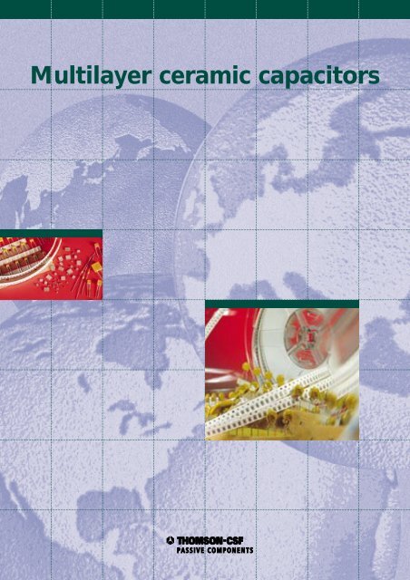
<strong>Multilayer</strong> ceramic capacitors
<strong>TPC</strong>, a subsidiary of THOMSON CSF, is a worldwide electronic component manufacturer, with over<br />
40 years experience in ceramic capacitors and offers a complete package covering design, manufacture,<br />
just-in-time delivery and quality assurance for ceramic capacitors.<br />
Our continued development in new materials and improved technology enables us to extend the<br />
range of products described in this brochure.<br />
Our Sales, Marketing and Product Development Departments will provide you with full technical support<br />
to meet your requirements and help you for customized product design.<br />
SAINT-APOLLINAIRE (France)<br />
PENANG (Malaysia)<br />
Information furnished is believed to be accurate and reliable. However THOMSON CSF PASSIVE<br />
COMPONENTS assumes no responsibility for the consequences of use of such information nor for any<br />
infringement of patents or other rights of third parties which may result from its use. No licence is<br />
granted by implication or otherwise under any patent or patent rights of <strong>TPC</strong>. Specifications mentioned<br />
in this publication are subject to change without notice. This publication supersedes and replaces<br />
all information previously supplied. © 1997 <strong>TPC</strong> - Printed in France - All rights reserved.<br />
These products are manufactured and commercialized by <strong>TPC</strong>.<br />
1
Introduction<br />
General characteristics p. 4<br />
Dielectric characteristics and classification p. 6<br />
How to order p. 8<br />
Selection guide p. 9<br />
Radial moulded multilayer ceramic capacitors<br />
Contents<br />
MC04/05/08/10C - CE11/13-CE61/62/63/64 p. 10<br />
MC04/05/08/10G - CN30/31-CN61/62/63/64<br />
MJ05/08G - CN19 p. 12<br />
MK05/06C - CC05/CC06 p. 14<br />
MK05/06G - CK05/CK06<br />
MQ05C p. 16<br />
MQ05/06G - CN50/CN60<br />
Radial dipped multilayer ceramic capacitors (“ECOCAP”)<br />
EC04/05/08C - CE72/73/74 - CE77/78/79 p. 18<br />
EC04/05/08G - CN77/78/79<br />
EC04/05/08Z - CN72/73/74<br />
EC04/05/08W<br />
Taping characteristics p. 20<br />
Packaging p. 22<br />
Recommendation for use p. 23<br />
Manufacturing process and quality assurance p. 24<br />
Quality and Reliability p. 26<br />
World wide sales offices p. 28<br />
3
GENERAL CHARACTERISTICS<br />
The real characteristics of a capacitor can be described<br />
using conventional physical parameters and an equivalent<br />
electrical circuit displayed hereafter :<br />
C the capacitance measures the capacitor aptitude<br />
to store electrical charges Q under a voltage V : Q<br />
= C.V<br />
C R<br />
the rated capacitance is obtained according to the<br />
building of the capacitor.<br />
K the dielectric constant, specific to each material<br />
(less than 100 for type I materials, from 2000 up to<br />
10 000 for type II materials),<br />
S the surface of the electrodes,<br />
t the thickness of the dielectric layer ; these parameters<br />
determine the value of the capacitor<br />
C = K S<br />
t<br />
T.C. the temperature coefficient of the capacitance is<br />
expressed in ppm/°C for stable type I dielectrics.<br />
³C/C is used for type II dielectrics and is expressed in %<br />
of change of the capacitance in a fixed temperature<br />
range.<br />
U R<br />
UDC UAC UP U E<br />
R p<br />
C<br />
Rp<br />
the rated voltage is the maximum voltage that can<br />
be applied to the capacitor in continuous operation.<br />
It can be constituted by :<br />
a direct current component<br />
an alternative component with<br />
the peak voltage.<br />
the test voltage guarantees that the capacitor<br />
withstands U R with a sufficient safety margin.<br />
represents the global losses (Polarization losses +<br />
insulation losses).<br />
Under DC voltage the parallel resistance is reduced to :<br />
Ri the insulation resistance, and measures the<br />
imperfection of the dielectric.<br />
Cp<br />
Rs<br />
Ls<br />
Introduction<br />
4<br />
R S<br />
L S<br />
or ESR (Equivalent Series Resistance) accounts<br />
for the imperfection of the conductivity of the electrodes<br />
and connections.<br />
or series inductance depends on the geometry of<br />
electrodes and connections, leads length ...<br />
Cp takes into account dielectric environment of the capacitor<br />
(coating ...) but is generally neglected except to<br />
describe very high frequency behaviour of the capacitor.<br />
Rp, Rs, Ls, Cp can be considered as parasitic<br />
effects. They generate energy losses and a dephasing<br />
ϕ between voltage and current slightly different of<br />
90°. The loss angle δ = (90° - ϕ) is commonly used<br />
with<br />
tg δ the tangent of loss angle which is also called :<br />
DF or dissipation factor.<br />
Q the quality factor is the ratio between the stored<br />
energy and the dissipated energy. It measures the<br />
quality of the capacitor and can be expressed as<br />
Q = 1/tg δ<br />
F being the frequency of the AC signal and<br />
ω the pulsation of this signal with ω = 2 πF<br />
Z the complex impedance of the capacitor is therefore<br />
given by the relation (neglecting Cp) :<br />
Z = Rs + j Ls ω +<br />
1<br />
= R + j X<br />
1<br />
+ j Cω<br />
Rp<br />
(the tangent of the loss angle tg δ can also be<br />
expressed as tg δ = R<br />
X<br />
so, neglecting LS for LS ω < 1<br />
Cω<br />
tg δ = RsCω +<br />
1<br />
+<br />
RpCω<br />
1<br />
R2 pCω F RS<br />
F RP<br />
the series resonance frequency of the capacitor is<br />
the frequency where the capacitance reactance is<br />
exactly compensated by the inductive reactance due<br />
to Ls<br />
Lsω = 1 or ω = 1<br />
or FRS =<br />
1<br />
Cω LsC 2π LsC<br />
the parallel resonance frequency occurs when Ls<br />
is compensated by Cp :<br />
FRP =<br />
1<br />
2π LsCp<br />
Between FRS and FRP , the capacitor reacts as an<br />
inductance, but still blocking DC.
The equivalent electrical circuit can be simplified<br />
using approximations according to the frequency :<br />
- At F = F RS the circuit is reduced to<br />
Z = Rs<br />
- For high frequencies Rs but below FRS Z = Rs+1/jCω<br />
tg δ = RsCω<br />
C Rs<br />
- For low frequencies Z =<br />
1<br />
1<br />
+ jCω<br />
Rp<br />
C<br />
tg δ =<br />
1<br />
RpCω<br />
VERY HIGH FREQUENCIES BEHAVIOUR OF LEADED<br />
CAPACITORS<br />
– Below the serie resonance frequency a radial MLC may<br />
be represented by this equivalent circuit :<br />
ø<br />
Rp<br />
C ESR Ls<br />
– Ls is essentially due to the leads (shape, pitch and<br />
length)<br />
Ls = L1 (chip) + L 2 (leads)<br />
This parasitic inductance has a large impact on the serie<br />
resonance frequency :<br />
Fr =<br />
1<br />
so Fr is ~ a . 1<br />
2 π L.C L<br />
Parallel leads inductance calculation<br />
Ls (nH) = 0.4 l[ In 2.P + 0.25 - P<br />
ø l<br />
• • •<br />
Rs<br />
Z (Ω)<br />
l<br />
Introduction<br />
Frs<br />
]<br />
F(Hz)<br />
5<br />
RELIABILITY<br />
<strong>Ceramic</strong> capacitors reliability is related to two main factors<br />
:<br />
• A voltage derating : life time is proportional to the power<br />
“n” of the derating applied :<br />
U rated<br />
τ = a ( ) n<br />
U use<br />
n ~ 2 for NP0<br />
n ~ 3.4 for X7R<br />
U rated<br />
THUS THE HIGHER ( ) the longer the life.<br />
U use<br />
• A temperature derating : life time is inversely proportional<br />
to the temperature of operation :<br />
τ = a ( 1 1<br />
-<br />
T use T rated<br />
THUS THE LOWER the temperature of use, the longer<br />
the life.<br />
)
Introduction<br />
DIELECTRICS CHARACTERISTICS AND CLASSIFICATION<br />
CECC<br />
Dielectric EIA<br />
MIL<br />
<strong>TPC</strong> code C Z G W<br />
TYPE I II<br />
Maximum capacitance change<br />
over temperature range<br />
No DC voltage applied<br />
Rated DC voltage applied<br />
Tangent of loss angle<br />
DF<br />
Insulation resistance<br />
1B / CG<br />
COG / NPO<br />
COG / BP<br />
0 ± 30 ppm/°C<br />
CR > 50 pF<br />
tgδ 15.10-4 5 pF < CR 50 pF<br />
Tgδ 1.5 ( 150 + 7).10 -4<br />
CR<br />
2R1<br />
X7R<br />
–<br />
Climatic category 55/125/56<br />
+ 30 % – 80 %<br />
± 15 % ± 20 % ± 15 % + 22 % – 56 %<br />
6<br />
+ 20 % – 30 % + 15 % – 25 % + 30 % – 90 %<br />
Ri 100 G Ri 10 G<br />
or Ri x C R 1000 s Ri x C R 100 s<br />
25/085/56<br />
10/085/56<br />
Ageing (typical) 0 % 1 % per decade 5 % per decade<br />
MEASUREMENT CONDITIONS<br />
Reference temperature 20°C ± 1°C<br />
Test voltage 2.5 x U R / 5 s and Im < 50 mA<br />
Insulation resistance Um applied = rated voltage / 1 min<br />
Insulation resistance<br />
to earth<br />
Measuring Frequency<br />
(Capacitance and<br />
tangent)<br />
(With :Um, Im, Fm = Measuring parameters)<br />
2C1<br />
–<br />
BZ<br />
U = U R x 2.5<br />
- Type I : CR 1000 pF ❽ F m = 1 MHz<br />
CR > 1000 pF ❽ F m = 1 kHz<br />
- Type II : CR 100 pF ❽ F m = 1 MHz<br />
CR > 100 pF ❽ F m = 1 kHz<br />
]<br />
]<br />
2X1<br />
–<br />
BX<br />
U m = 1 V<br />
U m = 0.5 V<br />
2F4<br />
Z5U<br />
–<br />
Tgδ 250.10 -4 Tgδ 300.10 -4
Introduction<br />
DIELECTRICS CHARACTERISTICS AND CLASSIFICATION<br />
Capacitance and tangent of loss angle as a function of temperature<br />
TYPE I TYPE II<br />
ΔC/C (%)<br />
0.4<br />
0.2<br />
0<br />
-0.2<br />
-0.4<br />
-0.6<br />
NPO/CG<br />
-40 -20 0 +20 +40 +60 +80 +100 +120<br />
tgδ (10 -4)<br />
Capacitance and tangent of loss angle as a function of DC voltage<br />
ΔC/C (%)<br />
20<br />
0<br />
-20<br />
Capacitance and tangent of loss angle as a function of frequency<br />
ΔC/C (%)<br />
1<br />
0<br />
-1<br />
NPO/GC<br />
10 20 30 40 50 60 70 80 90 100<br />
NPO/CG<br />
tgδ (10 -4)<br />
Capacitance as a function of time (ageing)<br />
30<br />
20<br />
10<br />
70<br />
60<br />
50<br />
40<br />
30<br />
20<br />
10<br />
U DC (V)<br />
100 Hz 1 kHz 10 kHz 100 kHz 1 MHz<br />
F<br />
10 MHz<br />
dC/C (%)<br />
30<br />
20<br />
10<br />
0<br />
Z 5 U<br />
X 7 R<br />
N P 0<br />
T (°C)<br />
ΔC/C (%)<br />
40<br />
20<br />
0<br />
-20<br />
-40<br />
-60<br />
-80<br />
X7R/2R1/2C1/BX<br />
-40 -20 0 +20 +40 +60 +80 +100 +120<br />
ΔC/C (%)<br />
10<br />
0<br />
-20<br />
-40<br />
-60<br />
-80<br />
X7R/2C1/BX<br />
10 20 30 40 50 60 70 80 90 100<br />
7<br />
tgδ (10 -4)<br />
TYPE I TYPE II<br />
tgδ (10 -4)<br />
TYPE I TYPE II<br />
-10<br />
1 10 100 1000 10000<br />
TIME (Hr)<br />
tgδ (10 -4) ΔC/C (%)<br />
20<br />
10<br />
10<br />
0<br />
-10<br />
X7R/2R1/2C1/BX<br />
-20<br />
F<br />
100 Hz 1 kHz 10 kHz 100 kHz 1 MHz 10 MHz<br />
100<br />
10<br />
700<br />
600<br />
500<br />
400<br />
300<br />
200<br />
100<br />
U DC (V)<br />
1000<br />
100<br />
10<br />
T (°C)<br />
ΔC/C (%)<br />
40<br />
20<br />
0<br />
-20<br />
-40<br />
-60<br />
-80<br />
ΔC/C (%)<br />
40<br />
20<br />
0<br />
-20<br />
-40<br />
-60<br />
-80<br />
tgδ (10 -4) ΔC/C (%)<br />
10<br />
0<br />
-10<br />
Z5U/2F4<br />
-40 -20 0 +20 +40 +60 +80 +100 +120<br />
Z5U/2F4<br />
10 20 30 40 50 60 70 80 90 100<br />
Z5U/2F4<br />
tgδ (10 -4)<br />
tgδ (10 -4)<br />
100<br />
10<br />
U DC (V)<br />
tgδ (10 -4)<br />
-20<br />
F<br />
100 Hz 1 kHz 10 kHz 100 kHz 1 MHz 10 MHz<br />
1000<br />
100<br />
10<br />
700<br />
600<br />
500<br />
400<br />
300<br />
200<br />
100<br />
T (°C)
ORDERING EXAMPLE<br />
1<br />
How to order<br />
2 3 4 5 6 7 8 9 10 11 12 13<br />
E C 0 4 Z E 0 1 0 3 K C A<br />
Types<br />
MC04<br />
MC05<br />
MC08<br />
MC10<br />
MJ05<br />
MJ08<br />
MQ05<br />
MQ06<br />
MK05<br />
MK06<br />
EC04<br />
EC05<br />
EC08<br />
C<br />
Z<br />
Class<br />
[<br />
[<br />
[<br />
COG<br />
NPO<br />
2R1<br />
X7R<br />
G BX<br />
2C1<br />
[<br />
W 2F4<br />
Z5U<br />
Rated<br />
Voltage<br />
D = 50/63 V<br />
E = 100 V<br />
F = 200 V<br />
G = 250 V<br />
Note :<br />
For MJ, MK<br />
moulded types<br />
voltage is inferred<br />
by the size<br />
and the capacitance<br />
value.<br />
Write 0 (zero) in<br />
the 6th digit<br />
case.<br />
Capacitance (EIA code)<br />
Capacitance expressed by 2<br />
significant figures<br />
7th digit : 0 (zero)<br />
8th and 9th digits : the 2 significant<br />
figures of the capacitance value<br />
10th digit :<br />
– for values 10 pF and 990 µF :<br />
the number of ZEROS to be added<br />
to the capacitance values<br />
– for values 1 pF and 9.9 pF :<br />
the figure 9 signifying that the<br />
capacitance value is to be<br />
multiplied by 0.1<br />
– for values < 1 pF : the figure 8<br />
signifying that the capacitance<br />
values is to be multiplied by 0.01.<br />
Examples : 1000 pF : 0102<br />
8.2 pF : 0829<br />
0.47 pF : 0478<br />
Capacitance expressed by 3<br />
significant figures<br />
7th, 8th and 9th digits : the 3<br />
significant figures of the capacitance<br />
value<br />
10th digit :<br />
– for values > 100 pF and 990 µF :<br />
the number of ZEROS to be added<br />
to the capacitance value<br />
– for values > 10 pF and < 100 pF :<br />
the figure 9 signifying that the<br />
capacitance value is to be<br />
multiplied by 0.1<br />
– for values > 1 pF and < 10 pF :<br />
the figure 8 signifying that the<br />
capacitance value is to be<br />
multiplied by 0.01.<br />
Examples : 196 pF : 1960<br />
47.2 pF : 4729<br />
8.28 pF : 8288<br />
8<br />
Tolerance<br />
C < 10 pF Code<br />
± 0.25 pF C<br />
± 0.5 pF D<br />
± 1 pF F<br />
C 10 pF Code<br />
± 1 % F<br />
± 2 % G<br />
± 5 % J<br />
± 10 % K<br />
± 20 % M<br />
– 20 + 80 % Z<br />
Suffix<br />
Suffix is defined<br />
according to :<br />
- lead spacing<br />
- lead shape<br />
- taping<br />
- packaging<br />
For details,<br />
see table page 21
Moulded<br />
Radial<br />
Dipped<br />
Style<br />
MC 04 MC 05/08/10<br />
MJ05/MK05 MJ08/MK06<br />
MQ 05 MQ 06<br />
EC 04 EC 05 EC 08<br />
Selection guide<br />
<strong>TPC</strong><br />
MC*<br />
04/05/08/10<br />
MJ05/08<br />
MK*<br />
05/06<br />
MQ05/06<br />
EC<br />
04/05/08<br />
EC<br />
04/05/08<br />
EC<br />
04/05/08<br />
EC<br />
04/05/08<br />
Types<br />
Dielectric<br />
Electrical characteristics<br />
Standards<br />
CECC/MIL<br />
type/class Rated<br />
voltage<br />
Capacitance range<br />
CE 13N/13L<br />
CE 11L<br />
CE 61/62/63/64<br />
CE 31/31N<br />
CN 30<br />
CN 61/62/63/64<br />
CN 19<br />
CC 05/06<br />
CK 05/06<br />
9<br />
–<br />
CN 50/60<br />
CE 72/73/74<br />
CE 77/78/79<br />
CN 77/78/79<br />
CN 72/73/74<br />
–<br />
I - NPO/COG<br />
(C)<br />
II - 2C1<br />
(G)<br />
II - 2C1<br />
(G)<br />
I - NPO/COG<br />
(C)<br />
II - BX<br />
(G)<br />
I - NPO/COG<br />
(C)<br />
II - 2C1<br />
(G)<br />
I - NPO/COG<br />
(C)<br />
II - 2C1<br />
(G)<br />
II - X7R<br />
2R1<br />
(Z)<br />
II - Z5U/2F4<br />
(W)<br />
100 V 1 pF ... 10 nF<br />
63 V 1 pF ... 33 nF<br />
100 V 120 pF ... 330 nF<br />
63 V 120 pF ... 1 µF<br />
250 V 10 pF ... 10 nF<br />
100 V 1.2 nF ... 100 nF<br />
63 V 12 nF ... 1 µF<br />
200 V 1 pF ... 2.2 nF<br />
100 V 1.1 nF ... 10 nF<br />
50 V 4.3 nF ... 18 nF<br />
200 V 10 pF ... 10 nF<br />
100 V 1.2 nF ... 100 nF<br />
50 V 12 nF ... 1 µF<br />
200 V 1 pF ... 220 pF<br />
100 V 1 pF ... 1 nF<br />
250 V 10 pF ... 10 nF<br />
100 V 1.2 nF ... 100 nF<br />
63 V 12 nF ... 1 µF<br />
200 V 4.7 pF ... 10 nF**<br />
100 V 4.7 pF ... 27 nF**<br />
50/63 V 820 pF ... 47 nF**<br />
100 V 1 nF ... 470 nF**<br />
50/63 V 10 nF ... 1 µF**<br />
200 V 820 pF ... 330 nF**<br />
100 V 1 nF ... 1 µF**<br />
50/63 V 10 nF ... 1 µF**<br />
200 V 100 nF ... 680 nF**<br />
100 V 10 nF ... 2.2 µF**<br />
50/63 V 33 nF ... 3.3 µF**<br />
* High reliability<br />
<strong>Multilayer</strong> capacitors, especially moulded types can be produced in high reliability versions, according to the current<br />
ESA/SCC specifications and levels. Our MC and MK types appear on the European Space Agency qualified part list.<br />
** Range extension<br />
For high capacitance values and larger sizes, see catalogue “<strong>Ceramic</strong> capacitors for professional applications”.<br />
Page<br />
10/11<br />
12/13<br />
14/15<br />
16/17<br />
18/19
MC 04-05-08-10 NP0 : CE/11L-13L-13N-61-61N-62-62N-63-64<br />
2C1 : CN/30-31-31N-61-61N-62-62N-63-64<br />
Size<br />
0.5<br />
Type<br />
P<br />
Dimensions (mm)<br />
Dimensions (mm)<br />
L H h1t Ø P<br />
± 0.5 max ± 0.5 ± 0.2 ± 5% ± 0.2<br />
Obs.<br />
MC04 3.5 4.5 3.5 2.5 0.6 2.54<br />
MC04 3.5 4.5 3.5 2.5 0.6 5.08 SUFFIX HB<br />
MC05 5 6 5 2.5 0.6 2.54<br />
MC05 5 6 5 2.5 0.6 5.08 SUFFIX HB<br />
MC08 7.5 8.5 7.5 2.5 0.6 5.08<br />
MC10 10 11 10 3.5 0.8 5.08<br />
Marking<br />
L t<br />
L<br />
h 1<br />
12 min H<br />
MC 04 MC 05 08 10<br />
ø<br />
2C1<br />
63 V<br />
97 03<br />
2n7 K<br />
0.5<br />
P<br />
THOMSON logo - class<br />
rated voltage<br />
date code (IEC62)<br />
capacitance (IEC62)<br />
tolerance (IEC62)<br />
h 1<br />
H<br />
12 min<br />
ø<br />
t<br />
10<br />
<strong>TPC</strong> TYPE<br />
CECC APPROVALS :<br />
NPO : 30601 - 001<br />
2C1 : 30701 - 011<br />
QPL : LNZ<br />
MC04C ... CE13L - CE61<br />
MC04C ... HB CE13N - CE61N<br />
CECC TYPES<br />
NPO 2C1<br />
MC04G ... CN31 - CN61<br />
MC04G ... HB CN31N - CN61N<br />
MC05C ... CE13L - CE62<br />
MC05C ... HB CE13N - CE62N<br />
MC05G ... CN31 - CN62<br />
MC05G ... HB CN31N - CN62N<br />
MC08C ... CE13L - CE63<br />
MC08G ... CN30/31 - CN63<br />
MC10C ... C11L/13L - CE64<br />
MC10G ... CN30/31 - CN64<br />
Capacitance tolerances & associated series<br />
NP0 2C1<br />
C < 10 pF<br />
± 0.25 pF : E12<br />
± 0.5 pF : E12<br />
C 10 pF<br />
± 1 % : E96<br />
± 2 % : E48<br />
± 5 % : E24<br />
± 10 % : E12<br />
± 5 % : E24<br />
± 10 % : E12<br />
± 20 % : E6
MC 04-05-08-10 NP0 : CE/11L-13L-13N-61-61N-62-62N-63-64<br />
2C1 : CN/30-31-31N-61-61N-62-62N-63-64<br />
Dielectric Class NP0 2C1<br />
Size 04 05 08 10 04 05 08 10<br />
Voltage 100 V 63 V 100 V 63 V 100 V 63 V 100 V 63 V 100 V 63 V 100 V 63 V 100 V 63 V 100 V 63 V<br />
Cap. range Code<br />
1.0 pF 0109<br />
1.2 0129<br />
1.5 0159<br />
1.8 0189<br />
2.2 0229<br />
2.7 0279<br />
3.3 0339<br />
3.9 0399<br />
4.7 0479<br />
5.6 0569<br />
6.8 0689<br />
8.2 0829<br />
10 0100<br />
12 0120<br />
15 0150<br />
18 0180<br />
22 0220<br />
27 0270<br />
33 0330<br />
39 0390<br />
47 0470<br />
51 0510<br />
56 0560<br />
68 0680<br />
82 0820<br />
100 0101<br />
120 0121<br />
150 0151<br />
180 0181<br />
220 0221<br />
270 0271<br />
330 0331<br />
390 0391<br />
470 0471<br />
560 0561<br />
680 0681<br />
750 0751<br />
820 0821<br />
1.0 nF 0102<br />
1.2 0122<br />
1.5 0152<br />
1.8 0182<br />
2.2 0222<br />
2.7 0272<br />
3.3 0332<br />
3.9 0392<br />
4.7 0472<br />
5.6 0562<br />
6.8 0682<br />
8.2 0822<br />
10 0103<br />
12 0123<br />
15 0153<br />
18 0183<br />
22 0223<br />
27 0273<br />
33 0333<br />
39 0393<br />
47 0473<br />
56 0563<br />
68 0683<br />
82 0823<br />
100 0104<br />
120 0124<br />
150 0154<br />
180 0184<br />
220 0224<br />
270 0274<br />
330 0334<br />
390 0394<br />
470 0474<br />
560 0564<br />
680 0684<br />
820 0824<br />
1.0 µF 0105<br />
11
MJ 05-08 2C1 : CN19<br />
Size<br />
Dimensions (mm)<br />
Type<br />
H<br />
12 min<br />
Dimensions (mm)<br />
L H t Ø P<br />
± 0.2 ± 0.2 ± 0.2 ± 5% ± 0.2<br />
MJ05 4.8 4.8 2.3 0.6 5.08<br />
MJ08 7.4 7.4 2.3 0.6 5.08<br />
Marking<br />
L<br />
P<br />
MJ 05 MJ 08<br />
1.14 max<br />
t<br />
ø<br />
2C1<br />
CN19 A<br />
250 V<br />
97 03<br />
1n K<br />
H<br />
12 min<br />
L<br />
P<br />
THOMSON logo - class<br />
type - variant<br />
rated voltage<br />
date code (IEC62)<br />
capacitance (IEC62)<br />
tolerance (IEC62)<br />
t<br />
ø<br />
12<br />
APPROVALS :<br />
CECC : 30701 - 016<br />
QPL : LNZ<br />
Capacitance tolerances & associated series<br />
± 5 % : E24<br />
± 10 % : E12<br />
± 20 % : E6
MJ 05-08 2C1 : CN19<br />
Dielectric Class 2C1<br />
Size 05 08<br />
Voltage 250 V 100 V 63 V 250 V 100 V 63 V<br />
Cap. range Code<br />
10 pF 0100<br />
12 0120<br />
15 0150<br />
18 0180<br />
22 0220<br />
27 0270<br />
33 0330<br />
39 0390<br />
47 0470<br />
56 0560<br />
68 0680<br />
82 0820<br />
100 0101<br />
120 0121<br />
150 0151<br />
180 0181<br />
220 0221<br />
270 0271<br />
330 0331<br />
390 0391<br />
470 0471<br />
560 0561<br />
680 0681<br />
820 0821<br />
1.0 nF 0102<br />
1.2 0122<br />
1.5 0152<br />
1.8 0182<br />
2.2 0222<br />
2.7 0272<br />
3.3 0332<br />
3.9 0392<br />
4.7 0472<br />
5.6 0562<br />
6.8 0682<br />
8.2 0822<br />
10 0103<br />
12 0123<br />
15 0153<br />
18 0183<br />
22 0223<br />
27 0273<br />
33 0333<br />
39 0393<br />
47 0473<br />
56 0563<br />
68 0683<br />
82 0823<br />
100 0104<br />
120 0124<br />
150 0154<br />
180 0184<br />
220 0224<br />
270 0274<br />
330 0334<br />
390 0394<br />
470 0474<br />
560 0564<br />
680 0684<br />
820 0824<br />
1.0 µF 0105<br />
13
MK 05-06 NP0 : CC05-06<br />
BX : CK05-06<br />
Size<br />
Dimensions (mm)<br />
Dimensions (mm)<br />
Type<br />
H<br />
12 min<br />
L H t Ø P<br />
± 0.2 ± 0.2 ± 0.2 ± 5% ± 0.2<br />
MK05 4.8 4.8 2.3 0.6 5.08<br />
MK06 7.4 7.4 2.3 0.6 5.08<br />
Marking / NP0<br />
capacitance<br />
L<br />
P<br />
CC05CG<br />
102 K<br />
200 V<br />
97 03<br />
1n 0 k<br />
Marking / BX<br />
capacitance<br />
MK 05 MK 06<br />
1.14 max<br />
tolerance<br />
t<br />
ø<br />
size - class MIL<br />
capacitance - tolerance (EIA)<br />
THOMSON logo - rated voltage<br />
date code (IEC62)<br />
CK05BX<br />
size - class (MIL)<br />
470 K<br />
capacitance - tolerance (EIA)<br />
200 V<br />
THOMSON logo - rated voltage<br />
97 03 date code (IEC62)<br />
47p k<br />
tolerance<br />
H<br />
12 min<br />
L<br />
P<br />
t<br />
ø<br />
14<br />
STANDARDIZATION :<br />
NPO : MIL-C-20 ❽ CC05 - CC06<br />
BX : MIL-C11015D ❽ CK05 - CK06<br />
Capacitance tolerances & associated series<br />
NP0 BX<br />
C < 10 pF<br />
± 0.25 pF : E12<br />
± 0.5 pF : E12<br />
C 10 pF<br />
± 1 % : E96<br />
± 2 % : E48<br />
± 5 % : E24<br />
± 10 % : E12<br />
± 5 % : E24<br />
± 10 % : E12<br />
± 20 % : E6
MK 05-06 NP0 : CC05-06<br />
BX : CK05-06<br />
Dielectric Class NP0 BX<br />
Size 05 06 05 06<br />
Voltage 200 V 100 V 50 V 200 V 100 V 50 V 200 V 100 V 50 V 200 V 100 V 50 V<br />
Cap. range Code<br />
1.0 pF 0109<br />
1.2 0129<br />
1.5 0159<br />
1.8 0189<br />
2.2 0229<br />
2.7 0279<br />
3.3 0339<br />
3.9 0399<br />
4.7 0479<br />
5.6 0569<br />
6.8 0689<br />
8.2 0829<br />
10 0100<br />
12 0120<br />
15 0150<br />
18 0180<br />
22 0220<br />
27 0270<br />
33 0330<br />
39 0390<br />
47 0470<br />
56 0560<br />
68 0680<br />
82 0820<br />
100 0101<br />
120 0121<br />
150 0151<br />
180 0181<br />
220 0221<br />
270 0271<br />
330 0331<br />
360 0361<br />
390 0391<br />
470 0471<br />
560 0561<br />
680 0681<br />
820 0821<br />
1.0 nF 0102<br />
1.2 0122<br />
1.5 0152<br />
1.8 0182<br />
2.2 0222<br />
2.4 0242<br />
2.7 0272<br />
3.3 0332<br />
3.9 0392<br />
4.3 0432<br />
4.7 0472<br />
5.6 0562<br />
6.8 0682<br />
8.2 0822<br />
10 0103<br />
12 0123<br />
15 0153<br />
18 0183<br />
22 0223<br />
27 0273<br />
33 0333<br />
39 0393<br />
47 0473<br />
56 0563<br />
68 0683<br />
82 0823<br />
100 0104<br />
120 0124<br />
150 0154<br />
180 0184<br />
220 0224<br />
270 0274<br />
330 0334<br />
390 0394<br />
470 0474<br />
560 0564<br />
680 0684<br />
820 0824<br />
1.0 µF 0105<br />
15
MQ 05-06 NP0 : –<br />
2C1 : CN50-60<br />
Size<br />
h1<br />
H<br />
Dimensions (mm)<br />
Dimensions (mm)<br />
Model Type<br />
L H h1 t Ø P<br />
± 0.2 ± 0.2 ± 0.2 ± 0.2 ± 5% ± 0.2<br />
CN50 MQ05 5 5 3.8 2.3 0.6 5.08<br />
CN60 MQ06 7.5 7.5 7.1 2.3 0.6 5.08<br />
Marking<br />
MQ 05 MQ 06<br />
L<br />
P<br />
250 V<br />
2C1 CN60<br />
97 03<br />
1n2 k<br />
t<br />
ø<br />
0.4<br />
THOMSON logo - rated voltage<br />
class - type<br />
date code (IEC62)<br />
capacitance (IEC62)<br />
tolerance (IEC62)<br />
L<br />
P<br />
h 1<br />
H<br />
12 min<br />
ø<br />
t<br />
16<br />
APPROVALS :<br />
CECC 30701-016<br />
QPL GAM-T1<br />
Capacitance tolerances & associated series<br />
NP0 2C1<br />
C < 10 pF<br />
± 0.25 pF : E12<br />
± 0.5 pF : E12<br />
C 10 pF<br />
± 1 % : E96<br />
± 2 % : E48<br />
± 5 % : E24<br />
± 10 % : E12<br />
± 5 % : E24<br />
± 10 % : E12<br />
± 20 % : E6
MQ 05-06 NP0 : –<br />
2C1 : CN50-60<br />
Dielectric Class NP0 2C1<br />
Size 05 05 06<br />
Voltage 200 V 100 V 250 V 100 V 63 V 250 V 100 V 63 V<br />
Cap. range Code<br />
1.0 pF 0109<br />
1.2 0129<br />
1.5 0159<br />
1.8 0189<br />
2.2 0229<br />
2.7 0279<br />
3.3 0339<br />
3.9 0399<br />
4.7 0479<br />
5.6 0569<br />
6.8 0689<br />
8.2 0829<br />
10 0100<br />
12 0120<br />
15 0150<br />
18 0180<br />
22 0220<br />
27 0270<br />
33 0330<br />
39 0390<br />
47 0470<br />
56 0560<br />
68 0680<br />
82 0820<br />
100 0101<br />
120 0121<br />
150 0151<br />
180 0181<br />
220 0221<br />
270 0271<br />
330 0331<br />
390 0391<br />
470 0471<br />
560 0561<br />
680 0681<br />
820 0821<br />
1.0 nF 0102<br />
1.2 0122<br />
1.5 0152<br />
1.8 0182<br />
2.2 0222<br />
2.7 0272<br />
3.3 0332<br />
3.9 0392<br />
4.7 0472<br />
5.6 0562<br />
6.8 0682<br />
8.2 0822<br />
10 0103<br />
12 0123<br />
15 0153<br />
18 0183<br />
22 0223<br />
27 0273<br />
33 0333<br />
39 0393<br />
47 0473<br />
56 0563<br />
68 0683<br />
82 0823<br />
100 0104<br />
120 0124<br />
150 0154<br />
180 0184<br />
220 0224<br />
270 0274<br />
330 0334<br />
390 0394<br />
470 0474<br />
560 0564<br />
680 0684<br />
820 0824<br />
1.0 µF 0105<br />
17
Size<br />
EC 04-05-08 CE/CN72-73-74<br />
CE/CN77-78-79<br />
Dimensions (mm) APPROVALS<br />
Marking<br />
H<br />
12 min<br />
Capacitance range - Type I<br />
Dielectric Class NP0<br />
Voltage 200 V 100 V 50 V<br />
Size<br />
Capacitance<br />
04 05 08 04 05 08 04 05 08<br />
4.7 to 470 pF<br />
560<br />
680<br />
820<br />
1 nF<br />
1.2<br />
1.5<br />
1.8<br />
2.2<br />
2.7<br />
3.3<br />
3.9<br />
4.7<br />
5.6<br />
6.8<br />
8.2<br />
10<br />
12<br />
15<br />
18<br />
22<br />
27<br />
33<br />
47<br />
EC 04 EC 04 ... HB EC 05 EC 05 ... HB<br />
L<br />
P<br />
104 M<br />
5 E<br />
t<br />
12 min<br />
ø<br />
EC 08<br />
12 min<br />
capacitance - tolerance (EIA)<br />
rated voltage<br />
D = 50 V<br />
E = 100 V<br />
F = 200 V<br />
THOMSON logo<br />
class<br />
C = NPO<br />
1 = 2C1<br />
3 = Z5U<br />
5 = X7R<br />
For EC04WD0104, marking is only “104”<br />
18<br />
Dimensions (mm)<br />
Type Size<br />
CECC :<br />
CECC 30601-015 : CE77/78/79 (NP0)<br />
CECC 30701-031 : CN77/78/79 (2C1)<br />
CECC 30701-045 : CN72/73/74 (2R1)<br />
CECC 30701-044 : EC04/05/08 (2F4)<br />
QPL LNZ :<br />
CE & CN72/73/74<br />
QPL GAM-T1 :<br />
CE & CN77/78/79<br />
L H t Ø P<br />
+ 0.6<br />
max max max ± 10% – 0.1<br />
EC04 04 3.8 5.3 2.5 0.5 2.54<br />
EC04...HB 04 3.8 5.8 2.5 0.5 5.08<br />
EC05 05 5 6.5 3.1 0.6 2.54<br />
EC05...HB 05 5 7.5 3.1 0.6 5.08<br />
EC08 08 7.6 9.6 3.8 0.6 5.08<br />
Types<br />
<strong>TPC</strong><br />
NP0<br />
CECC<br />
2C1 X7R Z5U<br />
EIA<br />
EC04 CE72.5 & CE77.5 CN77.5 CN72.5 – CC15<br />
EC04...HB CE72.1 & CE77.1 CN77.1 CN72.1 – –<br />
EC05 CE73.5 & CE78.5 CN78.5 CN73.5 – CC20<br />
EC05 ..HB CE73.1 & CE78.1 CN78.1 CN73.1 – –<br />
EC08 CE74.5 & CE79.5 CN79.5 CN74.5 – CC30<br />
Capacitance tolerances & associated series<br />
NP0 : C < 10 pF<br />
± 0.25 pF (C) : E12<br />
± 0.5 pF (D)<br />
10 pF C < 27 pf<br />
: E12<br />
± 5 % (J) : E24<br />
± 10 % (K) : E12<br />
C 27 pF<br />
± 1 % (F) : E96<br />
± 2 % (G) : E48<br />
± 5 % (J) : E24<br />
± 10 % (K) : E12<br />
2C1 : ± 10 % (K) : E12<br />
± 20 % (M) : E6<br />
X7R : ± 10 % (K) : E12<br />
± 20 % (M) : E6<br />
Z5U : ± 20 % (M) : E6
EC 04-05-08 CE/CN72-73-74<br />
CE/CN77-78-79<br />
Dielectric Class 2C1 X7R Z5U<br />
Voltage 100 V 50 V 200 V 100 V 50 V 200 V 100 V 50 V<br />
Size 04 05 08 04 05 08 04 05 08 04 05 08 04 05 08 04 05 08 04 05 08 04 05 08<br />
Cap. range Code<br />
0.82 nF 0821<br />
1 0102<br />
1.2 0122<br />
1.5 0152<br />
1.8 0182<br />
2.2 0222<br />
2.7 0272<br />
3.3 0332<br />
3.9 0392<br />
4.7 0472<br />
5.6 0562<br />
6.8 0682<br />
8.2 0822<br />
10 0103<br />
12 0123<br />
15 0153<br />
18 0183<br />
22 0223<br />
27 0273<br />
33 0333<br />
39 0393<br />
47 0473<br />
56 0563<br />
68 0683<br />
82 0823<br />
100 0104<br />
120 0124<br />
150 0154<br />
180 0184<br />
220 0224<br />
270 0274<br />
330 0334<br />
390 0394<br />
470 0474<br />
560 0564<br />
680 0684<br />
820 0824<br />
1.0 µF 0105<br />
1.2 0125<br />
1.5 0155<br />
1.8 0185<br />
2.2 0225<br />
2.7 0275<br />
3.3 0335<br />
Note : For higher capacitance values and larger sizes, see our catalogue “<strong>Ceramic</strong> capacitors for professional applications”<br />
19
For automatic insertion, the following types can be<br />
ordered taped either in AMMOPACK or on REEL. For<br />
taped devices, it is necessary to specify the height (H<br />
or H o) which is the distance between the tape axis<br />
(sprocket holes axis) and the sitting plane on the printed<br />
circuit board.<br />
Dimensions (mm)<br />
Dimensions (mm)<br />
L H I<br />
330 46 290<br />
Taping characteristics<br />
CHARACTERISTICS OF THE TAPE (in accordance to IEC 286-2)<br />
Value Tolerance Dimension characteristics<br />
18 + 1 / – 0.5 W Leading tape width<br />
6 ± 0.3 W0 Adhesive tape width<br />
9 + 0.75 / – 0.5 W1 Sprocket hole position<br />
3 max W2 Distance between the tops of the tape and the<br />
adhesive<br />
4 ± 0.2 D0 Diameter of sprocket hole<br />
16/19.5 ± 0.5 H0<br />
Distance between the tape axis and the seating plan<br />
of the component<br />
30.5 max H1<br />
Distance between the tape axis and the top of<br />
component body<br />
REEL AND AMMOPACK PACKAGING<br />
H<br />
H<br />
D 0<br />
P 1<br />
P0<br />
P ΔP ΔP<br />
L<br />
d<br />
F H0<br />
20<br />
— Straight leads :<br />
H represents the distance between the sprocket holes<br />
axe and the bottom plane of component body (base<br />
of resin or base of stand off).<br />
— Kinked, flat and snap-in leads :<br />
Ho : distance between the sprocket holes axe and the<br />
base of the knee (kinked) or the bottom of the flat<br />
part (flat leads) or the waist.<br />
Value Tolerance Dimension characteristics<br />
12.7 ± 0.2 P0 Sprocket holes pitch<br />
254 ± 1 – Distance between 21 consecutive holes 20 pitches<br />
0.7 ± 0.2 1 Total thickness of tape<br />
2.54 5.08 + 0.6 / – 0.1 F Lead spacing<br />
5.08 3.85 ± 0.7 P1 Distance between the sprocket hole axis and the<br />
lead axis<br />
12.7 ± 1.0 P Spacing of components<br />
0.5 0.6 0.63 ± 10 % d Lead diameter<br />
0 ± 1.3 ³P Verticality of components<br />
0 ± 2 ³h Alignment of components<br />
AMMOPACK REEL<br />
I Ø 31<br />
H 1<br />
• A maximum of 3 consecutive components may be missing from the tape, surrounded by at least 6 filled positions.<br />
The number of missing components may not exceed 0.5 % of the total per packing module.<br />
• The tape leader and trailer exhibit 8 or 9 blank positions.<br />
t<br />
W2<br />
W0<br />
W1<br />
W<br />
AA section<br />
Ø 8<br />
Dimensions (mm)<br />
30<br />
A<br />
Δh<br />
Ø 360<br />
Δh<br />
Adhesive tape<br />
interlayer paper<br />
42<br />
48<br />
Marking on this side<br />
A<br />
inside<br />
outside
Taping characteristics<br />
Table below indicates the suffixes to be specified when ordering to get the required kink and packaging<br />
(12th and 13th digits of the product codification).<br />
Leads shape Types Packaging<br />
Min. lead length (bulk)<br />
or taping height Ho<br />
(± 0.5 mm)<br />
Pitch Suffix<br />
Bulk 12 2.54 - -<br />
H0<br />
2.54<br />
MC04/05<br />
Ammopack<br />
Reel<br />
Ammopack<br />
Reel<br />
16<br />
19.5<br />
2.54<br />
2.54<br />
CA<br />
CB<br />
CC<br />
CD<br />
Bulk 12 5.08 - -<br />
Straight<br />
H0<br />
5.08<br />
MC08/MC10*<br />
MK06/MJ08<br />
Ammopack<br />
Reel<br />
Ammopack<br />
Reel<br />
16<br />
19.5<br />
5.08<br />
5.08<br />
DA<br />
DB<br />
DC<br />
DD<br />
Bulk 12 5.08 - -<br />
H0<br />
5.08<br />
MJ05<br />
MK05<br />
Ammopack<br />
Reel<br />
Ammopack<br />
Reel<br />
16<br />
19.5<br />
5.08<br />
5.08<br />
DA<br />
DB<br />
DC<br />
DD<br />
Bulk 12 2.54 - -<br />
Straight<br />
H0<br />
2.54<br />
EC04<br />
EC05<br />
Ammopack<br />
Reel<br />
Ammopack<br />
Reel<br />
Bulk<br />
16<br />
19.5<br />
12<br />
2.54<br />
2.54<br />
5.08<br />
CA<br />
CB<br />
CC<br />
CD<br />
- -<br />
EC08<br />
Ammopack<br />
Reel<br />
16 5.08<br />
DA<br />
DB<br />
H0<br />
5.08<br />
Ammopack<br />
Reel<br />
19.5 5.08<br />
DC<br />
DD<br />
Bulk 12 5.08 HB<br />
max 40°<br />
5.08<br />
H0<br />
EC04<br />
EC05<br />
Ammopack<br />
Reel<br />
Ammopack<br />
Reel<br />
16<br />
19.5<br />
5.08<br />
5.08<br />
DQ<br />
DR<br />
DS<br />
DT<br />
Bulk 12 5.08 HL<br />
25° ± 5<br />
EC08<br />
Ammopack<br />
Reel<br />
16 5.08<br />
DL<br />
DM<br />
Kinked<br />
5.08<br />
H0<br />
Ammopack<br />
Reel<br />
19.5 5.08<br />
DN<br />
DP<br />
H0<br />
EC04<br />
EC05<br />
Bulk<br />
Ammopack<br />
Reel<br />
12<br />
16<br />
2.54<br />
2.54<br />
HE<br />
CE<br />
CF<br />
Snap-in<br />
Flat<br />
5.08<br />
5.08<br />
2.54<br />
5.08<br />
2.54<br />
2.54<br />
10 max<br />
H0<br />
H0<br />
H0<br />
9 max<br />
H0<br />
8 max<br />
H0<br />
h max<br />
EC04<br />
EC05<br />
EC04<br />
EC05<br />
EC04<br />
EC05<br />
EC08<br />
EC04<br />
EC05<br />
EC04<br />
EC05<br />
EC08<br />
* MC10 : bulk only<br />
Nota : Other lead lengths (for bulk products only) available upon request.<br />
21<br />
Bulk 12 5.08 HK<br />
Ammopack<br />
Reel<br />
16 5.08<br />
DE<br />
DF<br />
Bulk 12 2.54 HG<br />
Ammopack<br />
Reel<br />
16 2.54<br />
CG<br />
CH<br />
Bulk 12 5.08 HH<br />
Ammopack<br />
Reel<br />
16 5.08<br />
DG<br />
DH<br />
Bulk<br />
Ammopack<br />
Reel<br />
16 2.54<br />
CJ<br />
CK<br />
Ammopack<br />
Reel<br />
Bulk<br />
19.5 2.54<br />
CL<br />
CM<br />
Ammopack<br />
Reel<br />
16 5.08<br />
DZ<br />
D1<br />
Ammopack<br />
Reel<br />
19.5 5.08<br />
D2<br />
D3
PACKAGING QUANTITIES<br />
Packaging<br />
Quantity per size Specific packaging quantities<br />
Type/Size BULK AMMOPACK REEL<br />
MC04/MC05/MC08 500 2000 2000<br />
MC10 250 2000 2000<br />
MJ05/MJ08 500 2000 2000<br />
MK05/MK06 500 2000 2000<br />
MQ05/MQ06 500 2000 2000<br />
EC04 5000 2500 4000<br />
EC05 5000 2500 3500*<br />
EC08 2000 1500 2500**<br />
IDENTIFICATION - TRACEABILITY<br />
On every packaging, you will find a bar code label.<br />
This label gives systematic information on the type of product, part number, lot number, manufacturing date<br />
and quantity.<br />
An example is given below :<br />
1A69721080 /006<br />
500<br />
MJ08G00104K--<br />
970610<br />
This information allows complete traceability of the entire manufacturing process, from raw materials to<br />
final inspection.<br />
22<br />
* 3000 pieces for :<br />
EC05CE - 4700 pF - 5600 pF - 6800 pF<br />
EC05ZE/GE - 68 nF - 100 pF<br />
EC05WE - 220 nF - 330 nF - 470 nF<br />
EC05ZD - 150 nF - 220 nF<br />
EC05GD - 150 nF<br />
EC05WD - 470 nF - 680 nF - 1 µF<br />
** 2000 pieces for :<br />
EC08CE - 22 nF - 27 nF<br />
EC08ZE - 470 nF - 680 nF - 1 µF<br />
EC08GE - 470 nF<br />
EC08ZD/GD - 1 µF<br />
EC08WE - 1 µF - 1.5 µF - 2.2 µF<br />
Lot number<br />
Manufacturing date (YYMMDD)<br />
Quantity per packaging<br />
Part number
RADIAL LEAD TYPES EC04/EC05/EC08<br />
During the solder immersion time it is advisable :<br />
– To keep the leads free into the holes of the board.<br />
– Not to apply any strength on the component (in line<br />
with the leads or accross the body).<br />
θ °C<br />
280<br />
265<br />
260<br />
240<br />
220<br />
200<br />
Recommendation for use<br />
3<br />
Max. solder bath - or wave temp.<br />
EC04<br />
EC05/EC08<br />
5 10 15<br />
23<br />
– To lift the body of the component, at least by 2 mm<br />
from the PCB (applicable for EC04 2.54 mm straight<br />
leads).The component should not be exposed to the<br />
solder heat for more than the "time versus temperature"<br />
given by the chart below.<br />
Dipping time into<br />
solder
Manufacturing process and quality assurance<br />
CHIPS MANUFACTURING FOR LEADED CAPACITORS<br />
Incoming raw material<br />
Slurry production<br />
Slip casting<br />
Serigraphy<br />
Stacking/pressing/cutting<br />
Sintering<br />
Batch characterization<br />
Terminal plating<br />
Electrical sorting<br />
Quality control<br />
Storage<br />
MANUFACTURING PROCESS FOR MOULDED CAPACITORS<br />
<strong>Ceramic</strong> chip soldering<br />
Transfer moulding<br />
Polymerization<br />
Testing, marking & leads trimming<br />
Quality control<br />
Packaging<br />
Quality control<br />
Shipping consignment<br />
Outgoing shipping-verification<br />
24<br />
Inspection : every batch<br />
Viscosity : every batch<br />
Thickness : every batch<br />
Visual inspection : every batch<br />
Visual inspection : every batch<br />
Thermal cycle : every batch<br />
Microsection exam. and electrical charact. by sampling,<br />
every batch<br />
Visual inspection : every batch by sampling<br />
100 %, capacitance, dissipation factor, test voltage<br />
Every batch by sampling : capacitance, dissipation factor<br />
Insulation resistance, test voltage<br />
Temperature : every batch<br />
Every batch by sampling : spacing between leads<br />
Thermal cycle : every batch<br />
Visual : every batch by sampling<br />
Thermal cycle : every batch<br />
Electrical test : 100 %<br />
Capacitance, dissipation factor, insulation resistance, test voltage, visual<br />
Every batch by sampling (AQL) : capacitance, dissipation factor, insulation resistance,<br />
test voltage, visual inspection, dimensions, solderability. QA report : every batch<br />
Bulk : every batch quantity. On tape : dimensions, missing<br />
parts : every batch by sampling<br />
Every batch : label check and outgoing acceptance<br />
Every batch, every shipment, packaging, documentation
Manufacturing process and quality assurance<br />
RADIAL DIPPED CAPACITORS MANUFACTURING PROCESS (EC Types)<br />
<strong>Ceramic</strong> chip soldering<br />
Ultrasonic cleaning<br />
Epoxy coating<br />
Polymerization<br />
Testing, marking & leads trimming<br />
Quality control<br />
Packaging<br />
Quality control<br />
Shipping consignment<br />
Outgoing shipping<br />
25<br />
Temperature, visual inspection : every batch 100 %<br />
Every batch by sampling : spacing between leads<br />
Thermal cycle : every batch<br />
Thermal cycle : every batch<br />
Visual & dimension : every batch by sampling<br />
Thermal cycle : every batch<br />
Electrical test : every batch 100 % : capacitance, dissipation factor, insulation<br />
resistance, test voltage. Visual inspection : every batch by sampling<br />
Every batch by sampling (AQL) : capacitance, dissipation<br />
factor, insulation resistance, visual inspection, dimensions,<br />
physical test : solderability, polymerisation, tensile strength<br />
Bulk : every batch quantity<br />
On tape : visual inspection : every batch by sampling<br />
Every batch by sampling (AQL) : taping dimensions, missing<br />
parts, taping defects & label check<br />
Every batch, every shipment, packaging, documentation
QUALITY SYSTEM<br />
Quality and reliability<br />
A high level of performance, quality and service has been achieved in setting up a quality system based on the<br />
ISO 9000 standard.<br />
The system includes :<br />
• a quality manual ensuring the proper organization,<br />
• an incoming inspection,<br />
• a manufacturing process control and a final inspection,<br />
• reliability tests according to IEC 68, CECC 30600 and CECC 30700 standards,<br />
• continuous improvements programs.<br />
APPROVALS<br />
The quality of our products and organization has been recognized by the following approvals :<br />
* EC Types :<br />
ISO 9002<br />
Certificate of approval n° 928373<br />
EN 100 114-1<br />
Certificate of approval of manufacturer n° 004-96<br />
CECC 30601 AND CECC 30701<br />
See detailed data sheets on page 18<br />
Qualified Parts List LNZ-44-04<br />
Types CE 72/73/74 and CN 72/73/74<br />
Qualified Parts List GAM-T1<br />
Types CE 77/78/79 and CN 77/78/79<br />
* Moulded types :<br />
ISO 9001<br />
Certificate of approval n° 928367<br />
EN 100 114-1<br />
Certificate of approval of manufacturer n° 032-93 issue 3<br />
CECC 30601 and CECC 30701<br />
See detailed data sheets on pages 10 to 16<br />
Qualified Parts List LNZ-44-04<br />
Types CN 19, CE 11/13<br />
Qualified Parts List GAM-T1<br />
Types CN 50/60<br />
26
Quality and reliability<br />
TEST DESCRIPTION TEST CONDITION TEST REQUIREMENT<br />
(1) ROBUSTNESS OF IEC 68-2-21, Test Ua - Tensile • No visible damage<br />
TERMINATIONS Weight : 5 & 10N (Ecocap), • Crack along pant leg admissible<br />
Duration : 10 s (1 lead)<br />
IEC 68-2-21, Test Ub - Bending<br />
(same part different lead)<br />
2 bends - in the same direction<br />
(2) RESISTANCE TO IEC 68-2-20, Test Tb - Resist. to sol. heat • Marking legible<br />
SOLDERING HEAT* Immersion : 2.0 mm from component body • No visible damage<br />
IMMERSION IN SOLVENT Temp/Duration : 260°C/5 s • Delta C/C<br />
(Sample from (1)) IEC 68-2-46, Test Xa - Immersion in solvent<br />
Temp. / Duration : 23°C/5 min - 10 strokes Class W Class Z Class G Class C<br />
Solvent : 2 - propanol, Weight : 5N 20 % 15 % 10 % 0.5 % or 0.5 pF<br />
(3) RAPID CHANGE OF TEMP/ IEC 68-2-14, Test Na - Thermal shock • No criteria<br />
THERMAL SHOCK Ta=25°C (W), 55°C (C,G,Z) : Tb=85°C (W), 125°C (C,G,Z)<br />
Duration : 1 h/cycle ; nb of cycles : 5<br />
(4) VIBRATIONS IEC 68-2-6, Test Fc - Vibration • No visible damage<br />
(Sample from (3)) Freq range : 10...2000 Hz, amplitude : 0.75 mm<br />
Duration : 2 h/direction - 3 directions<br />
(5) SHOCKS IEC 68-2-27, Test Ea - Shock • No visible damage<br />
(Sample from (4)) Pulse shape : half sine • Delta C/C :<br />
Acceleration : 490 m/s/s or 50 g<br />
Pulse duration : 11 ms Class W Class Z Class G Class C<br />
3 shocks x 3 directions 20 % 15 % 10 % 1.0 % or 1 pF<br />
(6) CLIMATIC SEQUENCE IEC 68-2-2, Test B - Dry heat • Marking legible<br />
(Sample from (2) & (5)) Temp/Duration : 85°C (W), 125°C (C,G,Z)/16 h • No visible damage<br />
IEC 68-2-30, Test Db - Damp heat cycles • Delta C/C :<br />
Temp/Duration : 55°C/24 h Class W Class Z Class G Class C<br />
Humidity : 95 %<br />
IEC 68-2-1, Test A - Cold<br />
30 % 15 % 10 % 2.0 % or 1 pF<br />
Temp/Duration : 25°C (W), -55°C (C,G,Z)/2 h<br />
EC 68-2-30, Test Db - Damp heat cycles<br />
• DF<br />
70x10 -3<br />
70x10 -3<br />
50x10 -3<br />
2 x<br />
Duration : 24 h/remaining cycles original limit<br />
Humidity 95 %, Temp : -55°C • IR<br />
1 G or 1 G or 10 G or 10 G or<br />
25 s/C 25 s/C 100 s/C 100 s/C<br />
(7) DAMP HEAT IEC 68-2-3, Test Ca - Damp heat • No visible damage<br />
WITH VOLTAGE Temp/Duration : 40°C/56 days • Delta C/C :<br />
Humidity : 93 % RH Class W Class Z Class G Class C<br />
Applied voltage : UR 30 % 15 % 15 %W/V<br />
10 %W/out V<br />
2.0 % or 1 pF<br />
(8) DAMP HEAT<br />
WITHOUT VOLTAGE<br />
IEC 68-2-3, Test Ca - Damp heat<br />
Temp/Duration : 40°C/56 days<br />
• DF<br />
70x10 -3<br />
70x10 -3<br />
50x10 -3<br />
2 x<br />
Humidity : 93 % RH<br />
• IR<br />
original limit<br />
1 G or 1 G or 10 G or 10 G or<br />
25 s/C 25 s/C 100 s/C 100 s/C<br />
(9) ENDURANCE/ (CECC 30000, 30600, 30601-016, 30700, • No visible damage<br />
LIFE TEST 30701-031, 30701-045, 30701-044) • Delta C/C :<br />
Temp : 85°C (W), 125°C (C,G,Z) Class W Class Z Class G Class C<br />
Duration : 1000 h 30 % 15 % -15 % ... +5 % 3.0 % or 1 pF<br />
Applied voltage : 1.5 U R (2 U R in particular cases) • DF<br />
70x10 -3<br />
27<br />
70x10 -3<br />
50x10 -3<br />
1.5 x<br />
original limit<br />
• IR<br />
2 G or 2 G or 10 G or 10 G or<br />
50 s/C 50 s/C 100 s/C 100 s/C<br />
(10) C = (T) TEMP (CECC 30000, 30600, 30601-016, 30700, • Delta C/C :<br />
COEFFICIENT 30701-031, 30701-045, 30701-044) Class W Class Z Class G Class C<br />
Test temp : -25°C/+85°C (W), -55°C/+125°C (G,Z) +22 -56 % ± 15 % +20 -30 % 0±30 ppm/°C<br />
-55°C/+85°C/+125°C (C) Um = 0 Um = 0 Um = UR Um = 0<br />
±20%, Un=0<br />
* Recovery : 1-2 h
AMERICAS<br />
BRAZIL<br />
THOMSON-CSF COMPONENTS BRASIL Ltda<br />
Av. Prof. Vicente Rao, 1620<br />
CEP 0436-001<br />
SAO PAULO - BRASIL<br />
Tel. : (5511) 5247713<br />
Fax : (5511) 2473059<br />
USA<br />
THOMSON-CSF PASSIVE COMPONENTS U.S.<br />
2211 - H Distribution Center Drive<br />
CHARLOTTE NC 28269<br />
Tel. : (1 704) 597 0766<br />
Fax : (1 704) 597 0553<br />
Worldwide sales offices<br />
EUROPE<br />
BENELUX<br />
THOMSON-CSF PASSIVE COMPONENTS BENE-<br />
LUX<br />
Avenue Louise 363 - B 10<br />
B-1050 BRUXELLES<br />
Tel. : (32 2) 627 03 45<br />
Fax : (32 2) 627 03 33<br />
INT’L SALES HEADQUARTER<br />
France & other countries<br />
THOMSON-CSF PASSIVE COMPONENTS<br />
29, avenue Carnot<br />
91349 MASSY Cedex France<br />
Tel. : (33) 1 69 93 41 41<br />
Fax : (33) 1 69 93 42 90<br />
GERMANY<br />
THOMSON-CSF PASSIVE COMPONENTS<br />
Perchtinger Strasse 3<br />
D-81379 MUNCHEN 70<br />
Tel. : (49 89) 78 79 0<br />
Fax : (49 89 )78 79 145<br />
ITALY<br />
THOMSON-CSF PASSIVE COMPONENTS<br />
Viale Fulvio Testi, 117<br />
20092 CINISELLO BALSAMO (MILANO)<br />
Tel. : (39 2) 660 15 510<br />
Fax : (39 2) 660 15 677<br />
SPAIN AND PORTUGAL<br />
THOMSON-CSF PASSIVE COMPONENTS<br />
C/Principe de Vergara, 204 - 1°B<br />
28002 MADRID<br />
Tel. : (34) 1 564 02 72<br />
Fax : (34) 1 564 19 40<br />
U.K. AND IRELAND<br />
THOMSON-CSF PASSIVE COMPONENTS<br />
P.O Box 6254<br />
Mountbatten House<br />
Basing View<br />
Basingstoke, RG 21 4XZ<br />
ENGLAND<br />
Tel. : (44) 1256 38 78 00<br />
Fax : (44) 1256 38 78 40<br />
28<br />
ASIA<br />
HONG KONG<br />
THOMSON-CSF PASSIVE COMPONENTS ASIA Ltd<br />
81F Rays Industrial Building<br />
71 Hung to Road<br />
Kwun Tong<br />
KOWLOON - HONG KONG<br />
Tel. : (852) 2389 00 22<br />
Fax : (852) 2797 80 81<br />
INDIA<br />
THOMSON-CSF PASSIVE COMPONENTS ASIA Ltd<br />
India Representative Office<br />
C 310 blue cross chambers<br />
Infantry road cross<br />
BANGALORE - 560001 INDIA<br />
Tel. : (91 80) 555 0566<br />
Fax : (91 80) 555 0566<br />
SINGAPORE<br />
THOMSON-CSF PASSIVE COMPONENTS SINGAPORE Pte Ltd<br />
171 Kallang Way n° 03-08<br />
Kolam Ayer Industrial Park<br />
SINGAPORE 349250<br />
Tel. : (65) 741 90 88<br />
Fax : (65) 741 92 88<br />
SHANGHAI<br />
THOMSON-CSF PASSIVE COMPONENTS ASIA Ltd<br />
Representative Office<br />
Room 6011 Hua Ting Guest House<br />
2525 Zhong Shan Xi Lu<br />
Shanghai 200030<br />
CHINA<br />
Tel. : (8621) 6481 4564<br />
Fax : (8621) 6481 4544<br />
TAIWAN<br />
THOMSON-CSF PASSIVE COMPONENTS TAIWAN Ltd<br />
12 F n° 149-16, Sec. 2<br />
Keelung Road. Taipei 110<br />
TAIWAN ROC<br />
Tel. : (8862) 378 6792<br />
Fax : (8862) 736 2142<br />
”Specifications mentioned in this publication<br />
are subject to change without notice”
Power capacitors<br />
Film capacitors<br />
Soft ferrite<br />
Non linear resistors<br />
<strong>Ceramic</strong> capacitors<br />
HEADQUARTERS : Avenue du Colonel Prat - 21850 Saint-Apollinaire - France - Tél. : (33) 03 80 71 74 00 - Fax : (33) 03 80 74 87 28 - Telex : THOM 616 780 F<br />
SALES OFFICES : 29, avenue Carnot - 91349 Massy Cedex - France - Tél. : (33) 01 69 93 41 41 - Fax : (33) 01 69 93 40 92 Telex : THOM 616 780 F<br />
SPC 898 - 12/97 - Design : PILOTE image, Conception réalisation : SOREGRAPH, Crédits photos : Dominique SARRAUTE, Le Square des Photographes


