Libretto HINDI 880 GB - Finto Toegangsbeheer
Libretto HINDI 880 GB - Finto Toegangsbeheer
Libretto HINDI 880 GB - Finto Toegangsbeheer

You also want an ePaper? Increase the reach of your titles
YUMPU automatically turns print PDFs into web optimized ePapers that Google loves.
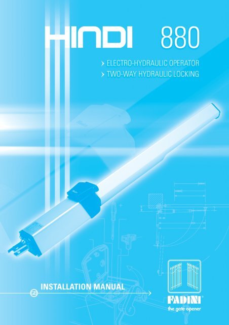
<strong>GB</strong> INSTALLATION MANUAL ®
2<br />
EARTH CONNECTION<br />
ELECTRIC<br />
CABLE<br />
LIVE (RED)<br />
COMMON (BLUE)<br />
REAR FIXING BRACKET<br />
OIL RESERVOIR BASE<br />
BINDING POSTS<br />
ELECTRIC MOTOR<br />
VALVE BODY<br />
OIL RESERVOIR ASSEMBLY<br />
CUTAWAY GENERAL VIEW<br />
MOTOR END PART<br />
STATOR<br />
ROTOR<br />
MOTOR END PART<br />
FADINI OIL A 15 by AGIP<br />
OIL-HYDRAULIC LOBE PUMP<br />
BIDIRECTIONAL VALVE BLOCK<br />
PRESSURE VALVE<br />
RELEASE DEVICE<br />
PROTECTION BOX<br />
TOP LID KEY
Two-way locking in “Open/Close” gate position<br />
OIL-HYDRAULIC OPERATOR FOR SWINGING GATES. ABOVE GROUND<br />
PISTON<br />
PISTON SHAFT<br />
FADINI OIL A 15 by AGIP<br />
LONG SCREW<br />
PISTON ASSEMBLY<br />
CYLINDER LINER<br />
PISTON HEAD<br />
ISOLATOR<br />
COVER LONG SCREW<br />
ADJUSTMENT NUT<br />
BALL BEARING FRONT JOINT<br />
COVER<br />
COVER PLUG<br />
PIC. 1<br />
3
INSTRUCTIONS FOR THE INSTALLATION OF <strong>HINDI</strong> <strong>880</strong>, AN ELECTRO-HYDRAULIC<br />
OPERATOR, TWO-WAY LOCKING IN OPEN AND CLOSE GATE POSITION.<br />
Keep to the following to achieve a perfectly working system.<br />
<strong>HINDI</strong> <strong>880</strong>, strong, functional and easy to install, is designed to be fitted to swinging gates by means of two plates, one is to be fixed<br />
to the gate and the other one to the gate post, pillar or brick pier. Check parts as in picture No. 2.<br />
REAR FIXING PLATE<br />
REAR FIXING BOLT<br />
SPECIFICATIONS<br />
TOP LID<br />
RELEASE KEY 1625<br />
VALVE ARRANGEMENT<br />
LOCK COVER<br />
KEY<br />
VALVE “OPEN”<br />
VALVE “CLOSE”<br />
LOCKING/RELEASE VALVE<br />
PLUG<br />
CIRCLIP<br />
BALL BEARING JOINT<br />
4 WIRE CABLE<br />
REAR END BLOCK<br />
SELF-LOCKING NUT<br />
REAR FIXING BRACKET<br />
CYLINDER/SHAFT<br />
VALVE PROTECTION ENCLOSURE<br />
OIL RESERVOIR ANODIZED<br />
RED LIVE<br />
BLACK NEUTRAL<br />
RED LIVE<br />
YELLOW/GREEN EARTH<br />
FRONT FIXING PLATE<br />
WITH PIN<br />
COVER ANODIZED<br />
ALUMINIUM<br />
PLUG<br />
NUTS<br />
SCREWDRIVER<br />
BOX WRENCH<br />
PIC. 2<br />
First unscrew the two nuts in the front end cap and remove the anodized, aluminium cover by pulling it horizontally and lay bare the<br />
cylinder, shaft and ball bearing joint for fitting and setting operations. Reinforcement plates are to be provided as shown in the pictures.<br />
Fixing to the gate post is by screwing, welding or setting with concret depending on the type of posts involved. Reinforcement plates<br />
fitted with anchor ended wedges are recommended for better grip in case of brick piers. Distances are strictly as shown in picture 3.<br />
130<br />
130<br />
80<br />
BALL BEARING JOINT<br />
50<br />
PISTON SHAFT<br />
- NUT<br />
- THREAD<br />
PIC. 3<br />
Provide a temporary fixing for the front fixing plate to the gate and swing the operator on to it. The shaft must be fully out, and the ball<br />
bearing joint fully screwed in, the gates in close position. Check alignment of the operators by means of a level. Picture 3.<br />
4
In events like power failure, <strong>HINDI</strong> <strong>880</strong> two- or one-way locking is designed to be released so that the gates can be pushed open by<br />
hand. Picture No. 4 shows how to do it. Lift the flap cover that protects the lock and open the top lid. Inside you will find the special<br />
release key part No. 1625. Turn it anti-clockwise by one complete turn. Should the gates be so wide that an electric lock is required<br />
for a better hold, after releasing the operator, remember to release the electric lock as well by its proper key, and then push the gates<br />
open. See picture 11-12.<br />
RELEASE<br />
3 rd OPERATION<br />
1625<br />
DETAIL OF THE VALVE ENCLOSURE.<br />
ALL THE VALVES ARE IN ONE BODY<br />
MANUAL RELEASE<br />
ANTI-CLOCKWISE.<br />
ONE COMPLETE TURN<br />
TIGHTEN<br />
TO LOCK<br />
1 st OPERATION<br />
2 nd OPERATION<br />
SPECIAL KEY<br />
FOR VALVE ENCLOSURE<br />
VALVE ENCLOSURE<br />
PIC. 4<br />
Before definitely fixing the front fixing plate to the gate, carry out some performance tests, the ball bearing joint still fully screwed in.<br />
Let the shaft come out to its full extension so to check if the above plate is in the correct position and fix it by welding. See picture 5.<br />
BALL BEARING JOINT<br />
REINFORCEMENT PLATE<br />
PROTECT THE SHAFT DURING WELDING<br />
PIC. 5<br />
After fixing the plate to the gate, it is important to unscrew the ball bearing joint by 5 or 6 mm, then re-tighten the nut. A sort of oil cushion<br />
is created in this way between the operator end casting “T”and the piston “S”. Pic. 6. This will prevent the ram from reaching the very<br />
limit of the permitted stroke and the gates are firmly held in closed gate position, as shown in pic. 10 on page 7.<br />
REINFORCEMENT PLATE<br />
“S”<br />
6<br />
“T”<br />
5 or 6 mm<br />
PIC. 6<br />
5
95°<br />
REAR END BLOCK WITH FIXING PARTS<br />
RELEASE KEY REMOVABLE FOR EXTRA SECURITY<br />
REF. No. 1625<br />
TWO-WAY LOCKING DEVICE<br />
SAFETY PRESSURE VALVE<br />
PROTECTION<br />
LID<br />
SPECIAL KEY AND LOCK<br />
BALL BEARING JOINT<br />
VALVE ENCLOSURE<br />
PLUG<br />
PIC. 7<br />
Make sure that the distances A and B are A 130 mm and B 130 mm, the centre of the gate hinge and the centre of the rear bracket of<br />
the operator to be referred to respectively. Distance D is never to be varied and must be equal to 80 mm from the centre of the ball<br />
bearing joint to the gate surface. Picture 8.<br />
IMPORTANT:<br />
HINGES ARE TO BE<br />
ALIGNED WITH THE<br />
GATE POST<br />
130<br />
130<br />
1˙010<br />
270<br />
80<br />
Open the valve enclosure by using the supplied key and<br />
release the operator by means of the special key No.<br />
1625 which comes inside the enclosure, already fitted on<br />
the release valve. The shaft will now be allowed to move<br />
freely in and out by pushing the gates by hand in a very<br />
smooth way. One complete cycle (open and close) is<br />
recommended so that the piston reaches the limit of the<br />
permitted stroke. Picture 7.<br />
PIC. 8<br />
SCREW DRIVER<br />
MAX PRESSURE VALVE CLOSE<br />
LID TO PROTECT FROM DUST<br />
MAX PRESSURE VALVE OPEN<br />
1625<br />
MANUAL RELEASE.<br />
ONE COMPLETE TURN<br />
ANTI-CLOCKWISE<br />
TURN THOROUGHLY CLOCKWISE<br />
TO RELOCK, AVOID<br />
OVERTIGHTENING<br />
PLEASE NOTE:<br />
THE VALVE THAT CONTROLS THE OPEN THRUST POWER<br />
MUST BE SUNK 2 TURNS DEEPER THAN THE CLOSE VALVE<br />
TO PREVENT THE FAILURE OF THE OPERATOR IN THE OPEN<br />
CYCLES WHEN HIGHER PRESSURE IS REQUIRED.<br />
PLUG<br />
SPECIAL KEY<br />
SUPPLIED WITH<br />
THE EQUIPMENT<br />
MANUAL RELEASE<br />
ANTI-CLOCKWISE BY<br />
ONE COMPLETE TURN<br />
PIC. 9<br />
6
Fit the gates with an electric lock in case it is installed the non locking operator. With the two-way locking operator it is recommended<br />
that the gates are not wider than two meters each. Should they be more than two meters an electric lock is to be installed to help the<br />
gates to be firmly held in the close position. Picture 10.<br />
With single gates the electric lock is to be installed horizontally at a suitable height from ground level. With double gates it is to be fitted<br />
vertically at the foot of the gates. Picture 11.<br />
GATE POST<br />
GATE STOP WITH<br />
LATCHING SOCKET<br />
GATE STOP.<br />
5 DEGREES MORE<br />
OPEN THAN THE OTHER ONE<br />
95°<br />
90°<br />
GATE STOP<br />
90 DEGREES OPEN<br />
ELECTRIC LOCK<br />
VERTICALLY INSTALLED<br />
GATE IN FULL OPEN POSITION<br />
PIC. 10<br />
PIC. 11<br />
The gate carrying the electric lock must be allowed to open 5 degrees<br />
more than the other one to prevent that on approaching the close<br />
position the two gates jam into each other. Important: gate stops are<br />
to be provided at open gate positions to prevent the pistons from<br />
reaching the limit of the permitted stroke. Picture 10.<br />
Should a mechanical latch be required for better hold of the gates in the close position on to the gate stop, the electric<br />
lock is to be fitted horizontally 70 cm from ground level. The gate with the electric lock must open 5 degrees more than<br />
the other one.<br />
ELECTRIC LOCK<br />
HORIZONTALLY FITTED<br />
GATE LEAF<br />
cm 70<br />
GATE LEAF<br />
LOCK KEEP<br />
MECHANICAL LATCH<br />
GATE STOP<br />
PIC. 12<br />
THIS OPERATION IS TO BE DONE ONCE THE<br />
PERFORMANCE TESTS ARE FINISHED<br />
IMPORTANT: TIGHTEN NUT “E”<br />
WITH CORRECT TOOLS<br />
PIC. 13<br />
7
Where brick piers are involved and the gates prehung or the gate hinges are mounted in the middle of the pier, there may be brickwork<br />
to cut out in order to allow clearance for the operator between the pier and the open gate. The fixing distances are always to be referred<br />
to the centre of the hinge and rear lock nut and bolt. Picture 14-15.<br />
CENTRE OF GATE HINGE<br />
130<br />
GATE LEAF<br />
130<br />
GATE LEAF<br />
70<br />
200<br />
130<br />
INDENTED GATE POST HORIZONTAL<br />
SECTION VIEW<br />
70<br />
200<br />
130<br />
1˙210<br />
CUT OUT BRICK PIER TO HAVE<br />
CLEARANCE FOR THE OPERATOR<br />
PIC. 14<br />
PIC. 15<br />
And now the electrical work. Keep to the diagram as shown in picture 18.<br />
N.W: CARRY OUT A RISK ANALYSIS IN COMPLIANCE WITH EN 12445 AND EN 12453 NORMS AND FIT ANY SAFETY DEVICE WHERE<br />
REQUIRED.<br />
General layout of the system complete with all the recommended accessories. Picture 16.<br />
6<br />
5<br />
4<br />
3<br />
2<br />
1<br />
13<br />
cable<br />
RG58<br />
2x1<br />
4x1<br />
12<br />
2x1<br />
11<br />
4x1<br />
4x1<br />
4x1,5<br />
2x1<br />
4x1,5<br />
3x1,5<br />
8<br />
9<br />
8<br />
4x1<br />
2x1<br />
10<br />
14<br />
7<br />
IMPORTANT: All the electrical equipment to be properly earthed<br />
1 - Flashing lamp MIRI 4<br />
2 - Photocell receiver POLO 44<br />
3 - Push button PULIN 3<br />
4 - Control box ELPRO 13 CEI<br />
5 - Plug-in radio receiver ASTRO 43<br />
6 - 230V 50/60Hz differential, magnetic<br />
thermal mains switch type 0.03A<br />
(beyond 100m use cables with 2.5mm Ø)<br />
7 - Post with photocell projector POLO 44<br />
8 - Electro-hydraulic operator <strong>HINDI</strong> <strong>880</strong><br />
9 - Electric lock<br />
10 - Post with photocell receiver POLO 44<br />
11 - Photocell transmitter POLO 44<br />
12 - Keyswitch PRIT 19<br />
13 - Aerial BIRIO A8<br />
14 - Radio transmitter ASTRO 43/2 Small<br />
JUNCTION BOX<br />
PIC. 16<br />
IMPORTANT: NO SHARP BEND.<br />
SMOOTH LONG LOOP IS RECOMMENDED<br />
PIC. 17<br />
8
CONNECTION DIAGRAM FOR SWING GATES ELPRO 13 exp<br />
26<br />
27<br />
28<br />
RADIO CONTROL<br />
PLUG-IN CARD SUPPORT<br />
1° CHANNEL<br />
24 V OUTPUT<br />
ON TO “0” THE DELAY<br />
IS OUT OF SERVICE<br />
MICRO PROCESSOR<br />
–<br />
7 0<br />
8<br />
+<br />
+<br />
TIMER SWITCHES<br />
LEAF DELAY<br />
TIMER<br />
CLOSE<br />
DWELL TIME<br />
1 AMP.<br />
FUSE: 24 V OUTPUT<br />
TERMINALS 12-13<br />
630 mA<br />
FUSE<br />
630 mA FUSE<br />
FLASHING LAMP<br />
TERMINALS FOR THE<br />
CONNECTION OF THE<br />
PUSH BUTTONS PULIN 3<br />
9<br />
+<br />
MOTOR RUN TIME<br />
OPEN & CLOSE<br />
CAPACITORS<br />
5 AMP. FUSE<br />
DIP-SWITCH<br />
ON<br />
1 2 3 4 5 6 7 8<br />
Should more pairs of photocells be<br />
required than the recommended<br />
quantity, fit an auxiliary transformer<br />
outside the control box.<br />
ON<br />
3 4<br />
OFF<br />
PULSE TWICE CONSECUTIVELY<br />
TO OPEN BOTH GATE LEAFS<br />
= PHOTOCELLS 2nd PAIR=<br />
INSIDE PHOTOCELLS N.C. CONTACT.<br />
IF OBSTRUCTED, THEY PREVENT THE<br />
GATES FROM OPENING, REVERSE GATE<br />
DIRECTION DURING CLOSE CYCLE.<br />
PEDESTRIAN MODE<br />
ONE PULSE OPENS<br />
ONE GATE LEAF ONLY<br />
1 2 3 4 5 6<br />
1 2 3 4 5 6 7 8 9 10 11 12 13 14 15 16 17 18 19 20 21 22 23 24 25<br />
PHOTO CELLS<br />
N.C. CONTACT<br />
COMMON<br />
OPEN SWITCH N.O. CONTACT<br />
CLOSE SWITCH N.O. CONTACT<br />
STOP SWITCH N.C. CONTACT<br />
RADIO CONTACT N.O.<br />
COMMON<br />
VOLTAGE OUTPUT<br />
ELECTRIC LOCK SUPPLY<br />
24 V INDICATOR 3 W MAX.<br />
7 8<br />
24 V OUTPUT<br />
A.C.<br />
MAX. PERMITTED LOAD:<br />
2 PAIRS PHOTOCELLS<br />
1 RADIO RECEIVER<br />
ALL OPERATIONS<br />
OPEN, CLOSE<br />
& REVERSE<br />
RADIO CONTACT<br />
SAFETY CONTACT N.C.<br />
COMMON<br />
12,5μF<br />
M1<br />
COMMON<br />
12,5μF<br />
M2<br />
ELECTRIC MOTORS<br />
SINGLE-PHASE<br />
230 V - 25 W max.<br />
NOTE WELL. For special applications, ie. to switch on lights<br />
- CCTV etc..., SOLID STATE RELAYS are recommended to be<br />
used only. Standard relays would affect the micro-processor.<br />
NOTE WELL: THIS PANEL IS TESTED TO OPERATE GATES ONLY<br />
THROUGH FADINI ACCESSORIES. NO WARRANTY IS<br />
ACKNOWLEDGED BY THE MANUFACTURER IN CASE THAT<br />
OTHER ACCESSORIES ARE USED OR NON CONFORMING<br />
APPLICATIONS ARE MADE WITHOUT THE MANUFACTURER’S<br />
APPROVAL.<br />
FLASHING LAMP<br />
SUPPLY VOLTAGE<br />
230 V SINGLE-PH.<br />
LED No. 1 - It switches on when voltage is supplied<br />
Drwg. No. 1643 P.C. BOARD<br />
ELECTRICAL WIRING DIAGRAM OF THE ELECTRONIC<br />
PROGRAMMER<br />
PIC. 18<br />
26 27 28 3<br />
3 4 5 6<br />
CONNECTION TO THE “PULIN 3”<br />
PUSH BUTTONS WITH STATUS INDICATION LEDS<br />
1 2 3 4 5 6 7 8 9 10 11 12 13<br />
COMMON<br />
OPEN N.O. CONTACT<br />
CLOSE N.O. CONTACT<br />
STOP N.C. CONTACT<br />
RADIO CONTACT<br />
TERMINAL BOARD<br />
N.O. N.C. N.O.<br />
OPEN STOP CLOSE<br />
STOP<br />
OPEN<br />
CLOSE<br />
COMMON<br />
1 2 3 4<br />
TERMINAL BOARD<br />
PRIT 19<br />
ELECTRICAL CONNECTIONS<br />
KEYSWITCH PRIT 19<br />
Once the connections have been made, do the first switching<br />
test through the control panel. Set the motor run timer so that<br />
the motor is allowed to run 4 - 5 seconds more than the gates.<br />
Set the other timers to meet the site requirements. Set DIP switch<br />
B No. 3 to automatic (ON): on pulsing to 4 - 8 the gates must be<br />
operated as pre-set, ie. opening and only after the dwell time,<br />
closing. Adjust the times through the respective timers. (See No.<br />
07, 08 and 09 drwg. No. 1643). With DIP switch “B” No. 3 to<br />
semiautomatic (OFF) one pulse opens the gates, a second pulse<br />
to 5 - 8 is needed to close the gates. Any one pulse to 7 - 8 will<br />
open, close or reverse the gates independently from the operation<br />
being performed. It is recommended to carefully read the<br />
instructions in the control box to have all the functions performed<br />
correctly.<br />
The 6 LEDS on the P.C. board indicate the following:<br />
led No. 1 It switches on when voltage is supplied.<br />
led No. 2 Photocells. Normally on. It switches off when the<br />
photocells are obstructed.<br />
led No. 3 Open - It switches on when the respective switch is<br />
activated.<br />
led No. 4 Close - It switches on when the respective switch is<br />
activated.<br />
led No. 5 Stop - Normally on. It switches off when the respective<br />
switch is activated.<br />
led No. 6 Radio - It switches on whenever a pulse is given,<br />
either from remote control, keyswitch or push buttons.<br />
PIC. 19<br />
9
SPECIAL APPLICATIONS <strong>HINDI</strong> <strong>880</strong><br />
Drwg. No. 0987<br />
- 400 mm<br />
885<br />
210 A<br />
1˙275<br />
390<br />
GATE CLOSED<br />
GATE STOP FIXED<br />
TO THE GROUND<br />
0°<br />
180<br />
B<br />
PIC. 20<br />
Drwg. No. 1990<br />
COVER<br />
GATE STOP FIXED<br />
TO THE GROUND<br />
95°<br />
80<br />
B<br />
GATE STOP FIXED<br />
TO THE GROUND<br />
PIC. 21<br />
95°<br />
60 A<br />
10 mm<br />
750<br />
610<br />
60°<br />
- 150 mm<br />
MOST CRITICAL<br />
INCLINATION<br />
ADJUST THE SHAFT CONNECTION TO A<br />
SUITABLE DISTANCE SO THAT THERE IS A 10<br />
mn CLEARANCE BETWEEN THE COVER AND<br />
THE GATE WHEN THE OPERATOR LINE IS IN<br />
THE MOST CRITICAL POSITION, ie. ABOUT 60<br />
DEGREES INCLINED TO THE GATE LINE. IN<br />
MOST CASES THIS DISTANCE CAN BE<br />
CONSIDERED TO BE INCLUDED BETWEEN 90<br />
AND 100 mm, BUT THIS DISTANCE IS NOT<br />
APPLICABLE TO ALL INSTALLATIONS.<br />
GEOMETRY REQUIRED FOR THE MODEL 894 -<br />
895 - 896<br />
THE SUM OF A + B MUST TOTAL THE PISTON<br />
STROKE.<br />
140<br />
GATE CLOSED<br />
GATE STOP FIXED<br />
TO THE GROUND<br />
GEOMETRY REQUIRED FOR THE MODEL 891 -<br />
892 - 893.<br />
THE SUM OF A + B MUST TOTAL THE PISTON<br />
STROKE.<br />
Code <strong>880</strong>73<br />
FRONT FIXING LONGER<br />
BRACKET TO SUIT 400 mm RAM<br />
This page specifically refers to the special<br />
operators in the Hindi <strong>880</strong> range, ie. drwg. No.<br />
1990 - 150 mm, drwg. No. 0987 - 400 mm stroke<br />
and drwg. No. 2552 braking in open/close cycles.<br />
The detailed installation instructions that are<br />
contained in this manual apply to all the models<br />
in the Hindi <strong>880</strong> range.<br />
Only, please note that the items 881 - 891 - 894,<br />
that are non locking, have no manual release,<br />
and an external electric lock is required to hold<br />
the gates in the closed position. A temporary<br />
connection to the control panel is to be provided<br />
to drive out full movement of the shaft before<br />
installation (manual test).<br />
SPECIAL VERSIONS. BRAKING IN OPEN/CLOSE CYCLES (Drwg. No. 2552)<br />
t 19 t 8<br />
t 8 t 14<br />
STROKE 260<br />
C = 27 s<br />
A = 22 s<br />
GATE STOP<br />
t 25 t 13<br />
C = 38 s<br />
t 14 t 20<br />
STROKE 385<br />
A = 34 s<br />
GATE STOP<br />
130<br />
B<br />
80<br />
120 D<br />
B 220<br />
A<br />
740 260<br />
1˙000<br />
160<br />
A<br />
885<br />
1˙270<br />
385<br />
D<br />
10<br />
GATE<br />
STOP<br />
PIC. 22<br />
- 280 mm<br />
with BRAKE<br />
OPEN/CLOSE<br />
95°<br />
PLEASE NOTE:<br />
A VERY FINE ADJUSTEMENT IS REQUIRED<br />
FOR BRAKING CONTROL OF THE OPERATOR<br />
GATE STOP<br />
- 400 mm<br />
with BRAKE<br />
OPEN/CLOSE<br />
ADJUST THE SHAFT CONNECTION TO A SUITABLE DISTANCE SO THAT THERE IS A 10 mm<br />
CLEARANCE BETWEEN THE COVER AND THE GATE WHEN THE OPERATOR LINE IS IN THE<br />
MOST CRITICAL POSITION, ie. ABOUT 60 DEGREES INCLINED TO THE GATE LINE. IN MOST<br />
CASES THIS DISTANCE CAN BE CONSIDERED TO BE INCLUDED BETWEEN 90 AND 100<br />
mm, BUT THIS DISTANCE IS NOT APPLICABLE TO ALL INSTALLATIONS.<br />
95°
CONNECTION TWO MOVES TO<br />
POSITION THREE,<br />
THIS SHOULD REVERSE GATE OPERATION<br />
VOLTS 230 Hz 50<br />
FIXED CONNECTION<br />
CAPACITOR<br />
BLUE<br />
2 1 3<br />
RED<br />
YELLOW/GREEN<br />
MANUAL TEST<br />
TECHNICAL SPECIFICATIONS<br />
OVERALL DIMENSIONS<br />
OIL-HYDRAULIC PISTON<br />
Time for one stroke....................................................................................................24 s<br />
Pump flow rate - P5..........................................................................................1.4 l/min.<br />
Stroke ....................................................................................................................280 mm<br />
Cylinder bore Ø ......................................................................................................45 mm<br />
Piston shaft Ø.........................................................................................................20 mm<br />
Thrust power.....................................................................................................3˙000 Nm<br />
Working pressure .................................................................................1 MPa (10 bars)<br />
Max pressure ........................................................................................3 MPa (30 bars)<br />
Oil make...........................................................................................Fadini A 15 by AGIP<br />
Temperature ............................................................................................. _ 25°C + 80°C<br />
Weight of <strong>HINDI</strong> <strong>880</strong> complete .............................................................................11 Kg<br />
Max. gate weight...........................................................................................150/180 Kg<br />
I.P. standards complete.........................................................................................IP 553<br />
Dimensions (L.xW.xH.) ......................................................................1˙085x92x110 mm<br />
Duty cycle.............................................25 sec. Open - 30 sec. Dwell - 25 sec. Close<br />
Time of one complete cycle .....................................................................................80 s<br />
No. of complete cycles Open - Stop - Close...................................................45/hour<br />
No. of cycles a year, 8 hours a day...................................................................131˙000<br />
PIC. 23<br />
ELECTRIC MOTOR<br />
Horse power ................................................0.18 KW (0.25 HP)<br />
Voltage................................................................................230 V<br />
Frequency ..........................................................................50 Hz<br />
Absorbed power..............................................................250 W<br />
Absorbed current ..............................................................1.2 A<br />
Motor rotation speed.............................................1˙350 r.p.m.<br />
Capacitor.........................................................................12.5 μF<br />
Intermittent service..............................................................S 3<br />
86 x 86<br />
110<br />
75 58<br />
77<br />
1˙085<br />
92<br />
80<br />
730 280<br />
1˙010<br />
PIC. 24<br />
11
Meccanica Fadini recommends the control<br />
panel ELPRO 13 CEI to achieve an installation<br />
that is in conformity to the existing safety<br />
standards.<br />
The electronic programmer “ELPRO 13”<br />
incorporates and can provide all the functions<br />
which are required by the most demanding<br />
applications with swinging gates.<br />
In addition to the standard features of ELPRO<br />
9 (Drwg. No. 1310), the following requirements<br />
can be provided: “stroke reversing pulse”,<br />
pedestrian mode, stop in any gate position by<br />
holding down the remote control button. Among<br />
the added features and improvements of<br />
“ELPRO 13”, in conformity to the European<br />
safety standards, there is the mains rotary<br />
switch: it is fitted to the box cover and switches<br />
off the mains voltage whenever the cover is<br />
removed.<br />
CUT OFF<br />
MAINS SWITCH<br />
13 CEI<br />
SINGLE-PHASE<br />
N.W.<br />
With all the electro-hydraulic operators, once<br />
installed, you need to set the safety pressure<br />
valves to meet the gate pushing power/anti-crush<br />
requirements. The valve “OPEN” must be set to<br />
get higher pressure than “CLOSE”. The electric<br />
cable is factory-set and must be left free. The<br />
encoding remote control, the control box (preprogrommed<br />
to meet the most various operation<br />
requirements) and a wide range of safety<br />
accessories make the system fully automatic.<br />
STICKER FITTED ON TO THE<br />
ELECTRIC MOTOR<br />
®<br />
s.n.c.<br />
Via Mantova, 177/A - 37053 Cerea (VR) Italy - Tel. 0442 330422 r.a. - Fax 0442 331054<br />
MOTOR<br />
W<br />
VOLTS<br />
r.p.m.<br />
Nm<br />
2 PHASE<br />
250<br />
230<br />
1˙350<br />
3˙000<br />
CV<br />
A<br />
Hz<br />
μF<br />
0.25<br />
1.2<br />
50<br />
12.5<br />
Degree of protection IP 553<br />
Working pressure max. 3 MPa (30 Bars)<br />
OIL FADINI A15 BY AGIP<br />
MADE IN ITALY<br />
CHECKING AND MAINTENANCE:<br />
To achieve an optimum performance and longer life of the equipment and in observance of<br />
the safety regulations, it is recommended that inspetions and proper maintenance are made<br />
by qualified technicians to the whole installation ie. both the mechanical and electronic<br />
parts, as well as wiring.<br />
- Mechanical parts: maintenance every 6 months approx.<br />
- Electronic apparatus and safety equipment: maintenance every month.<br />
IMPORTANT WARNING NOTES<br />
- Before installing the equipment carry out a Risk Analysis and fit any required device<br />
in compliance with EN 12445 and EN 12453 Safety Norms.<br />
- It is recommended to keep to the instructions here outlined. Check the specifications<br />
on the motor sticker with your mains supply.<br />
- Dispose properly of the packaging: cardboard, nylon, polystyrene, through specializing<br />
companies.<br />
- Should the operator be removed, do not cut the electric cable. This must be properly<br />
removed from the terminal board in the junction box.<br />
- Switch off the mains switch before removing the junction box cover where the electric<br />
cable of <strong>HINDI</strong> <strong>880</strong> is terminated.<br />
- All the system must be earthed by using the yellow/green wire, marked by its specific<br />
symbol.<br />
- It is recommended to read the regulations, suggestions and remarks quoted in the<br />
booklet “Warnings”.<br />
04-2006<br />
EUROPEAN MARK CERTIFYING<br />
CONFORMITY TO THE ESSENTIAL<br />
REQUIREMENTS OF THE STANDARDS<br />
98/37/EC<br />
• DECLARATION OF CONFORMITY<br />
• GENERAL WARNINGS<br />
• EN 12453, EN 12445 STANDARDS<br />
• CEI EN 60204-1 STANDARDS<br />
• WARRANTY CERTIFICATE ON THE<br />
CUSTOMER’S REQUEST<br />
The “CE” mark certifies that the operator conforms<br />
to the essential requirements of the European<br />
Directive art. 10 EEC 73/23, in relation to the<br />
manufacturer’s declaration for the supplied items,<br />
in compliance with the body of the regulations ISO<br />
9000= UNI EN 29000. Automation in conformity to<br />
EN 12453, EN 12445 safety standard.<br />
®<br />
The growth of MECCANICA FADINI has always been based on the development of guaranteed<br />
products thanks to our “TOTAL QUALITY CONTROL” system which ensures constant quality<br />
standards, updated knowledge of the European Standards and compliance with their<br />
requirements, in view of an ever increasing process of improvement.<br />
Made in Italy<br />
AUTOMATIC GATE MANUFACTURERS<br />
®<br />
s.n.c.<br />
Distributor’s box<br />
The manufacturers reserve the right to change the products without any previous notice<br />
Via Mantova, 177/A - 37053 Cerea (Verona) Italy - Tel. +39 0442 330422 r.a. - Fax +39 0442 331054 - e-mail: info@fadini.net - www.fadini.net