Installation manual 4.2 Mb - Sonab Audio
Installation manual 4.2 Mb - Sonab Audio
Installation manual 4.2 Mb - Sonab Audio

Create successful ePaper yourself
Turn your PDF publications into a flip-book with our unique Google optimized e-Paper software.
ENGLISH / CONTENTS<br />
1. general installation notes<br />
2. Network overview<br />
2. Cloud 9 product range<br />
3–4. Wireless installation<br />
6. Wireless + wired installation<br />
7. Troubleshooting<br />
Note: <strong>Installation</strong>s examples on last pages in <strong>manual</strong><br />
GENERAl installations notes<br />
- Always try to have the CTX transmitter placed in the “middle” of the installation and at the same<br />
height as the CLS speakers are placed.<br />
- If the source is placed far away from the CTX it is possible to use an active USB extender cable<br />
(normally available up to 20m) to achieve best possible placement of the CTX.<br />
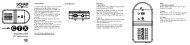
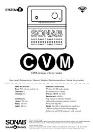
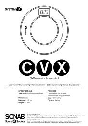
- The CVM should ideally also be placed in the same height as the CTX and CLS. The CVX volume<br />
control extender can be used to route the master volume control to a more convenient placement.<br />
- The CGV, CLS and CSW in wired mode uses a balanced audio signal so a cable with 3 conductors<br />
(+,g,-)are necessary to make the installation.<br />
- Be aware that it is only possible to go from a wireless speaker and then continue with wired installation.<br />
It is not possible to go from wired speaker and then make it wireless to the next speaker in line.<br />
- In a wireless installation always make sure that the same Channel and ID Code are being used (only<br />
exception is if CEX is being used). Otherwise there will not be any connection established between<br />
the units.<br />
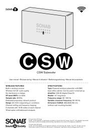
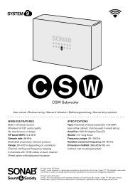
- In wireless mode the CSW subwoofer can be put on a separate zone volume, making it is easy to<br />
match the subwoofer volume to the rest of the system.<br />
- When using the CEX wireless extender make sure that CEX unit 1 is receiving same Channel as the<br />
CTX is transmitting. The CEX unit 2 must send out on a different channel than CEX unit 1 is receiving.<br />
Example: CEX unit 1 is receiving Channel 1 from the CTX, the CEX unit 2 must send out on channel<br />
2 or 3. The CLS and/or CSW that are receiving signal from CEX unit 2 must then also be set to<br />
channel 2. The ID Code should still be the same for the complete installation.