General Installation Manual - Better Energy AG
General Installation Manual - Better Energy AG
General Installation Manual - Better Energy AG

Create successful ePaper yourself
Turn your PDF publications into a flip-book with our unique Google optimized e-Paper software.
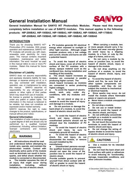
<strong>General</strong> <strong>Installation</strong> <strong>Manual</strong><br />
<strong>General</strong> <strong>Installation</strong> <strong>Manual</strong> for SANYO HIT Photovoltaic Modules. Please read this manual<br />
completely before installation or use of SANYO modules. This manual applies to the following<br />
products: HIP-200BA3, HIP-195BA3, HIP-190BA3, HIP-186BA3, HIP-180BA3, HIP-175BA3<br />
HIP-200BA5, HIP-195BA5, HIP-190BA5, HIP-186BA5, HIP-180BA5<br />
INTRODUCTION<br />
Thank you for choosing SANYO HIT*<br />
Photovoltaic (PV) modules. With proper<br />
operation and maintenance, SANYO HIT<br />
PV modules will provide you with clean,<br />
renewable solar electricity for many<br />
years. This manual contains important<br />
installation, maintenance and safety<br />
information. The word “module” as used<br />
in this manual refers to one or more PV<br />
modules. Retain this manual for future<br />
reference.<br />
Disclaimer of Liability<br />
SANYO does not assume responsibility<br />
and expressly disclaims liability for loss,<br />
damage, or expense arising out of, or in<br />
any way connected with installation,<br />
operation, use, or maintenance by using<br />
this manual. SANYO assumes no<br />
responsibility for any infringement of<br />
patents or other rights of third parties<br />
which may result from use of modules.<br />
No license is granted by implication or<br />
under any patent or patent rights. The<br />
information in this manual is believed to<br />
be reliable, but does not constitute an<br />
expressed and/or implied warranty.<br />
SANYO reserves the right to make<br />
changes to the product, specifications, or<br />
manual without prior notice.<br />
<strong>General</strong> Information<br />
The installation of solar modules requires<br />
a great degree of skill and should only be<br />
performed by a qualified licensed<br />
professional, including, without limitation,<br />
licensed contractors and licensed<br />
electricians.<br />
!!<br />
WARNING<br />
■ All instructions should be read<br />
and understood before attempting to<br />
install, wire, operate, and maintain the<br />
photovoltaic module. Contact with<br />
electrically active parts of the module<br />
such as terminals can result in burns,<br />
sparks, and lethal shock whether the<br />
module is connected or disconnected.<br />
■ The installer assumes the risk of<br />
all injury that might occur during<br />
installation, including, without<br />
limitation, the risk of electric shock.<br />
■ PV modules generate DC electrical<br />
energy when exposed to sunlight or<br />
other light sources. Although single<br />
modules produce only a low voltage<br />
and current, shocks and burns are still<br />
a potential hazard.<br />
■ To avoid the hazard of electric<br />
shock and injury, cover all of the front<br />
surface of the PV modules with a<br />
dense, opaque material such as the<br />
cardboard box, during installation and<br />
handling of the modules.<br />
■ The shock hazard increases as<br />
modules are connected in parallel<br />
producing higher current. The<br />
shock hazard increases as modules<br />
are connected in series producing<br />
higher voltages.<br />
■ To avoid the hazard of electric<br />
shock, work only under dry<br />
conditions, with dry modules and<br />
tools.<br />
■ Do not stand or step on a<br />
module to avoid the hazard of injury<br />
and damage to a module.<br />
■ Do not puncture or damage the<br />
back-sheet of a module, to avoid the<br />
hazard of electric shock and fire.<br />
■ To avoid the hazard of electric<br />
shock and injury, children and<br />
unauthorized persons should not be<br />
allowed near the installation of PV<br />
modules.<br />
■ To avoid the hazard of electric<br />
shock and injury, be sure to<br />
completely ground all modules.<br />
■ To avoid the hazard of electric<br />
shock, fire, and injury, do not<br />
disassemble the module, or remove<br />
any part installed by the<br />
manufacturer.<br />
■ Unauthorized persons--except<br />
the qualified licensed professional--<br />
should not open the cover of the<br />
junction box to avoid the hazard of<br />
electric shock.<br />
Provide suitable guards to prevent<br />
yourself from direct contact with 30<br />
VDC or greater to avoid the hazard<br />
of electric shock or injury.<br />
1<br />
■ When carrying a module, two<br />
or more people should carry it by<br />
its frame and wear non-slip gloves<br />
(to avoid injury by a slipping<br />
module, to a foot, or cuts by the<br />
edge of a frame, and so on).<br />
■ Do not carry a module by its<br />
wires or junction box, to avoid the<br />
hazard of electric shock, injury or<br />
damage to the module.<br />
■ Do not drop anything on the<br />
surfaces of a module, to avoid the<br />
hazard of electric shock, injury, and<br />
damage.<br />
■ To avoid the hazard of electric<br />
shock and fire, be sure that all<br />
other system components are<br />
compatible, and they do not<br />
subject the module to mechanical<br />
or electrical hazards.<br />
■ Since sparks may occur, do not<br />
install the module where flammable<br />
gases or vapors are present.<br />
■ Never leave a module unsupported<br />
or unsecured.<br />
■ Do not drop a module.<br />
■ Do not use or install broken<br />
modules to avoid the hazard of<br />
fire, electric shock, and injury.<br />
■ Do not artificially concentrate<br />
sunlight on a module to avoid the<br />
hazard of fire or damage.<br />
■ Do not touch the junction box<br />
terminals to avoid the hazard of<br />
electric shock and injury.<br />
■ Do not change the wiring of<br />
bypass diodes to avoid the hazard<br />
of electric shock and injury.<br />
!!<br />
CAUTIONS<br />
■ Use a module for its intended<br />
purpose only.<br />
■ Do not treat the back sheet and<br />
front surface with paint or adhesives<br />
to avoid reducing its’ functionality,<br />
damage, inoperable conditions, and<br />
other unknown troubles.<br />
© December 2005 Sanyo Electric Co., Ltd.<br />
All Rights Reserved
GENERAL SAFETY<br />
● The appropriate material should be<br />
Follow all permission, installation used for mounting hardware to prevent<br />
and inspection requirements. the module frame, mounting structure,<br />
● Before installing modules, contact the and hardware itself from corrosion.<br />
appropriate authorities to determine ● Install modules where they are not<br />
permissions, installation, and inspection<br />
requirements which should be followed.<br />
shaded by obstacles like buildings and<br />
trees. Especially pay attention to avoid<br />
● Electrically ground modules for all partially shading the modules by objects<br />
systems of any voltage. If not otherwise during the daytime.<br />
specified, it is recommended that ● Please contact your SANYO<br />
requirements of the latest National authorized representative with<br />
Electrical Code (USA) or Canadian Electric questions regarding mounting profiles<br />
Code (Canada) or other national or for modules.<br />
international electrical standards be used. Notes on <strong>Installation</strong><br />
● Be sure that the construction or structure ● Clearance between the module<br />
(roof, façade, etc.) where the modules are<br />
being installed, has enough strength. For<br />
frame and the mounting surface is<br />
required to allow cooling air to circulate<br />
modules mounted on roofs, special around the back of the module. This<br />
construction or structures may be required also allows any condensation or<br />
to help provide proper installation. Both moisture to dissipate. The module<br />
roof construction and module installation<br />
design have an effect on the fire resistance<br />
of a building. Improper installation may<br />
should never be sealed to the mounting<br />
surface with sealant that prevents air<br />
from circulating under the module.<br />
contribute to fire hazards. Additional ● To satisfy the UL fire class C rating<br />
devices such as ground fault, fuses, and<br />
disconnects may be required.<br />
for the modules, the recommended<br />
standoff height is 4 inches minimum. If<br />
● Do not use modules of different other mounting methods are used, this<br />
· specifications in the same system. may effect the fire class rating.<br />
● Follow all safety precautions of other<br />
Standard Operating Condition<br />
system components used.<br />
SANYO recommends that modules be<br />
operated under Standard Operating<br />
Conditions (SOC).<br />
UL Listing Information:<br />
To satisfy UL requirements, when<br />
installing the modules, be sure to:<br />
1) Use only stranded or solid copper<br />
single –conductor type UF cable or<br />
USE cable, rated sunlight resistant, for<br />
modules and interconnect wiring that<br />
is exposed to weather.<br />
2) Observe the requirements described<br />
in sections labeled INSTALLTION and<br />
SPECIFICATIONS.<br />
3) Grounding of the module frame is<br />
required. When ground wires greater<br />
than 6mm 2 (No.10 AWG) are required,<br />
the installer will need to provide<br />
suitable terminal connectors.<br />
INSTALLATION<br />
<strong>General</strong><br />
● Please read this guide completely<br />
before installation or use of the modules.<br />
This section contains electrical and<br />
mechanical specifications needed before<br />
using your SANYO PV modules.<br />
● Modules should be firmly fixed in<br />
place in a manner suitable to withstand<br />
all expected loads, including wind and<br />
snow loads.<br />
● Do not drill additional mounting holes<br />
in the module frames, as it will void the<br />
warranty.<br />
14<br />
<strong>Installation</strong> (reference)<br />
27 27<br />
Metal fitting<br />
(4 places)<br />
M6 Nut<br />
Spring washer<br />
Flat washer<br />
Metal fitting<br />
M6 Bolt/setscrew<br />
2<br />
f 8<br />
Mounting<br />
Structure Rail<br />
Metal fitting<br />
Mounting Structure Rail<br />
An installation location with conditions<br />
beyond SOC or with other Special<br />
Conditions (see below) should be avoided.<br />
SOC of SANYO modules is as follows:<br />
1. Standard Operating Conditions<br />
(1) The modules should be operated only<br />
in terrestrial applications. No space or<br />
other Special Conditions (see below).<br />
(2) The ambient temperature should be<br />
within –20℃ (-4 ° F) to 40℃ (104 ° F).<br />
(3) The relative humidity should be<br />
within 45% to 95%.<br />
(4)The installation place should be less<br />
than 1,000m (3,280ft) above sea level.<br />
<strong>Installation</strong>s more than 1,000m (3,280ft)<br />
are allowed only if the wind pressure<br />
load for a module is less than<br />
2,170N/m 2 (45PSF).<br />
Module<br />
Mounting Structure Rail<br />
2. Special Conditions<br />
( 1 ) The ambient temperature and<br />
installation place are different from SOC.<br />
(2) The salt damage is heavy at the<br />
installation place.<br />
(3) The hail and snow damage is heavy<br />
at the installation place.<br />
(4) The sand and dust damage is heavy<br />
at the installation place.<br />
(5) The air pollution, chemically active<br />
vapors, acid rain, and/or soot, etc. are<br />
heavy at the installation place.<br />
This referential figure is for HIP-xxxBA3 modules.<br />
Solar Module<br />
Solar Module<br />
End of Module Between Modules<br />
Figure 1. <strong>Installation</strong>
SPECIFICATIONS<br />
Notes on Specification<br />
(1) Rated electrical characteristics are<br />
within 10% of the values measured at<br />
Standard Test Conditions (STC). STC are:<br />
Irradiance of 1000W/m, 25℃ cell<br />
temperature, and solar spectral irradiance<br />
per IEC 60904-3.<br />
Mechanical / Electrical Specifications<br />
*HIT = Hetero junction with Intrinsic Thin-layer<br />
• Wiring should be protected to help<br />
ensure personal safety and to prevent its<br />
damage.<br />
• All modules connected in series<br />
should be of the same model number<br />
and/or type.<br />
• Do not connect modules in parallel<br />
without using a connection box.<br />
Module Wiring<br />
• The maximum number of modules<br />
that can be wired in series is seven (7).<br />
• The SANYO solar modules are not<br />
designed for “off-grid” or battery charging<br />
systems. It is not recommended to use<br />
them to charge batteries.<br />
• These modules contain factory<br />
installed bypass diodes. If these modules<br />
are incorrectly connected to each other,<br />
the bypass diodes, cables, or junction<br />
box may be damaged.<br />
Array Wiring<br />
The term “array” is used to describe the<br />
assembly of several modules on a<br />
support structure with associated wiring.<br />
Use copper wire that is sunlight resistant<br />
and is insulated to withstand the<br />
maximum possible system open circuit<br />
voltage. Check your local codes for<br />
requirements.<br />
Earth Ground Wiring<br />
Grounding should be carried out by<br />
the securement to the module or array<br />
frame to avoid the hazards of electric<br />
shock or fire. The array frame shall<br />
be grounded in accordance with NEC<br />
Article 250 (USA) or CEC in Canada.<br />
Each framed module has a hole in the<br />
shorter side frame rail, to connect a<br />
grounding conductor to the module<br />
metal frame (see Figure 2).<br />
Electrical Specification<br />
Model<br />
HIP-200BA3 HIP-195BA3 HIP-190BA3 HIP-186BA3 HIP-180BA3 HIP-175BA3 HIP-200BA5 HIP-195BA5 HIP-190BA5 HIP-186BA5 HIP-180BA5<br />
Cell Number in Series 96 96 96 96 96 96 96 96 96 96 96<br />
Rated Pow er, Watts (Pmax) 200 195 190 186 180 175 200 195 190 186 180<br />
Maximum Pow er Voltage (Vpm) 55.8 55.3 54.8 54.4 54.0 52.9 55.8 55.3 54.8 54.4 54<br />
Maximum Pow er Current (Ipm) 3.59 3.53 3.47 3.42 3.33 3.31 3.59 3.53 3.47 3.42 3.33<br />
Open Circuit Voltage (Voc) 68.7 68.1 67.5 67.0 66.4 65.7 68.7 68.1 67.5 67.0 66.4<br />
Short Circuit Current (Isc) 3.83 3.79 3.75 3.71 3.65 3.64 3.83 3.79 3.75 3.71 3.65<br />
Cell Type HIT* HIT* HIT* HIT* HIT* HIT* HIT* HIT* HIT* HIT* HIT*<br />
Maximum System Voltage (Voc) 600 600 600 600 600 600 600 600 600 600 600<br />
Factory Installed Bypass Diodes 4 4 4 4 4 4 4 4 4 4 4<br />
Mechanical Specification<br />
Model HIP-200BA3 HIP-195BA3 HIP-190BA3 HIP-186BA3 HIP-180BA3 HIP-175BA3 HIP-200BA5 HIP-195BA5 HIP-190BA5 HIP-186BA5 HIP-180BA5<br />
Length, mm (inches)<br />
Width, mm (inches)<br />
1319 (51.9)<br />
894 (35.2)<br />
Frame Depth , mm (inches)<br />
35 (1.4)<br />
60(2.4)<br />
Weight, kg (pounds) 14 (30.9)<br />
(2) The current output for the modules<br />
shown in the Specifications is<br />
measured at Standard Test Conditions.<br />
These conditions may not be frequently<br />
observed in actual practice.<br />
(3) Under normal conditions, a<br />
photovoltaic module may experience<br />
conditions that produce more current<br />
and/or voltage than reported at<br />
standard component test conditions.<br />
Accordingly, the values of Isc and Voc<br />
marked on UL listed modules should<br />
be multiplied by a factor of 1.25 when<br />
determining voltage ratings, conductor<br />
capacities, fuse sizes, and size of<br />
controls connected to the module output.<br />
USA: Refer to Section 690-8 of the<br />
U.S. National Electrical Code for an<br />
additional multiplying factor of 1.25<br />
which may be applicable.<br />
Mechanical Loading<br />
The modules should be mounted at the<br />
four quarter points by the means shown<br />
in Figure 3.1 and 3.2. This method offers<br />
a maximum loading of 2170N/m 2 (45PSF,<br />
in a static state) on the module surface.<br />
WIRING<br />
<strong>General</strong><br />
All wiring should be done in accordance<br />
with applicable electrical codes.<br />
Wiring methods should be in<br />
accordance with the NEC in USA or<br />
CEC in Canada.<br />
• All wiring should be done by a<br />
qualified, licensed professional.<br />
3<br />
Ground Location (1 place)<br />
Ground hole<br />
Junction Box<br />
Label<br />
Backside<br />
The ground hole is<br />
on the inside of the<br />
module frame.<br />
Figure 2.<br />
Module Ground Position
Dimensions<br />
Models (Standard): HIP-200BA3, HIP-195BA3, HIP-190BA3,<br />
HIP-186BA3, HIP-180BA3, HIP-175BA3<br />
Ground (1 place)<br />
Dimensions in mm<br />
Label<br />
negative ( - )<br />
78cm (30.7in)<br />
Junction Box<br />
positive ( + )<br />
63cm (24.8in)<br />
Cable<br />
Connector (MC TM Plug)<br />
Connector<br />
MC TM Plug<br />
Mount Locations (4 places)<br />
negative ( - ) positive ( + )<br />
Front<br />
Side<br />
Backside<br />
Figure 4. Configuration of<br />
Junction Box<br />
Note:<br />
Note: A module is installed on a<br />
platform A module should be attached<br />
on with standard setting range<br />
(shaded)<br />
a mount or support structure rail<br />
within the shaded range.<br />
Figure 3.1 Standard Model<br />
Dimensions<br />
Section A-A’<br />
Module Terminations<br />
A junction box as a terminal enclosure is equipped for<br />
electrical connections on SANYO modules. Modules are<br />
equipped with MC TM plugs as a terminal enclosure. Use<br />
these MC TM plugs for electrical connections.<br />
Please contact your SANYO authorized representative with<br />
questions regarding other electrical connections for<br />
modules.<br />
Junction Box and Terminals<br />
Modules equipped with one junction box contain terminals<br />
for both positive and negative polarity, and bypass diodes.<br />
One terminal is dedicated to each polarity (with the polarity<br />
symbols engraved onto the body of the junction box ) (see<br />
Figure 4).<br />
Conduit<br />
For applications where wire conduits are used, follow the<br />
applicable codes for outdoor installation of wires in conduits.<br />
Verify that all fittings are properly installed to protect wires<br />
against damage and prevent moisture intrusion.<br />
DIODES<br />
Bypass Diodes<br />
When the modules in series strings are shaded partially,<br />
it may cause reverse voltage across cells or modules,<br />
because the current from other cells in the same series<br />
is forced to flow through the shaded area. This may<br />
cause undesirable heating to occur. The use of a diode<br />
to bypass the shaded area can minimize both heating<br />
and array current reduction.<br />
All SANYO modules are equipped with factory installed<br />
bypass diodes. The factory installed diodes provide<br />
proper circuit protection for the systems within the<br />
specified system voltage, so that you do not need any<br />
other additional bypass diodes. Contact your authorized<br />
SANYO representative for proper diode type, if it is<br />
necessary to add or change diodes due to system<br />
specifications.<br />
4
For Dimensions More Information,<br />
Please Models (deep-frame): Contact HIP-200BA5, SANYO HIP-195BA5, HIP-190BA5,<br />
HIP-186BA5, HIP-180BA5<br />
Authorized Representatives<br />
Dimensions in mm<br />
at:<br />
www.sanyo.com/industrial/sol<br />
ar/representatives.cfm<br />
Ground (1 place)<br />
For further information, please<br />
contact:<br />
Label<br />
Junction Box<br />
negative (-)<br />
78cm (30.7in)<br />
positive ( + )<br />
63cm (24.8in)<br />
Connector (MC TM Plug)<br />
Front<br />
Mount Locations<br />
Side<br />
Backside<br />
Note: A module should be installed on a support structure in<br />
accordance with the following:<br />
Use four (4) symmetrical mounting points within set range A.<br />
Section A-A’<br />
Figure 3.2 Deep-Frame Model<br />
Dimensions<br />
MAINTAINENCE<br />
Some maintenance is recommended to<br />
maintain optimal output performance of<br />
the solar modules. If the module surface<br />
becomes dirty, it may reduce output<br />
power. It is recommended to clean the<br />
surface of the module with water and a<br />
soft cloth or sponge. A mild non-abrasive<br />
detergent may be applied for persistent<br />
dirt. It is also recommended to inspect<br />
the module’s electrical and mechanical<br />
connections annually.<br />
The return of any modules will not be<br />
accepted by SANYO unless prior<br />
written authorization has been given by<br />
SANYO.<br />
As part of our policy of continuous<br />
improvement SANYO reserves the right<br />
to change product specifications at any<br />
time without prior notice.<br />
If you need electrical and mechanical<br />
inspection or maintenance, it is<br />
recommended to have an authorized<br />
professional carry out the inspection or<br />
maintenance to avoid the hazard of<br />
electric shock and/or injury.<br />
5