SCR100 Charger - Exide Technologies
SCR100 Charger - Exide Technologies
SCR100 Charger - Exide Technologies

You also want an ePaper? Increase the reach of your titles
YUMPU automatically turns print PDFs into web optimized ePapers that Google loves.
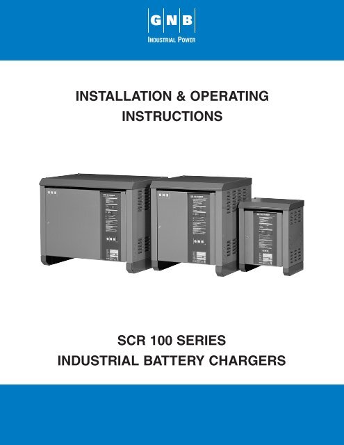
INSTALLATION & OPERATING<br />
INSTRUCTIONS<br />
SCR 100 SERIES<br />
INDUSTRIAL BATTERY CHARGERS
SCR 100 CHARGER<br />
WARRANTY<br />
This Warranty Agreement entered into between GNB <strong>Technologies</strong>, "GNB", and the Original User in respect to GNB electric vehicle<br />
battery chargers for electric vehicle usage.<br />
1.0 GENERAL<br />
GNB warrants that each new electric vehicle battery charger supplied by it, is of good workmanship and is free from any inherent<br />
mechanical defects, provided:<br />
1.1 The product is installed and operated in accordance with generally accepted industrial standards and in accordance with<br />
the printed instructions supplied with the charger.<br />
1.2 The charger is used under conditions for which it was designed and is not subject to misuse, negligence or accident.<br />
1.3 The charger receives proper care, protection, and maintenance under supervision of competent personnel.<br />
1.4 The charger is used within the published performance rating for the unit involved.<br />
1.5 The charger is used exclusively by the original user and by no other persons.<br />
2.0 PERSONS COVERED<br />
This warranty is extended by GNB only to the original user who purchases or leases a new charger product from GNB or one<br />
of its authorized representatives. The product purchased or leased under this agreement shall be used exclusively by the original<br />
user and its employees and by no other persons and, therefore, there shall be no third party beneficiary to this warranty.<br />
3.0 WARRANTY PERIOD<br />
The charger is warranted for four (4) years from the date of manufacture as determined by the product serial number, with<br />
the following exceptions:<br />
3.1 Power transformers, SCR's and silicon diodes are warranted for ten (10) years from the date of manufacture of the<br />
charger(s) of which they are a part.<br />
3.2 Primary switch contacts, fuses, bulbs, and filters are not warranted unless found to be defective prior to use.<br />
4.0 LIMITATION OF REMEDY<br />
Any claimed defect is subject to GNB's inspection and judgment, after the defective product has been returned by the original<br />
user at its expense to GNB’s designated point of shipment.<br />
4.1 GNB’s liability is limited to the repair of the defect or, at GNB’s option, the replacement of the defective parts. During the initial<br />
three (3) years of charger warranty period, GNB will bear all parts and labor costs of such repair or replacement. During year<br />
four (4) of the warranty, GNB will only cover parts, no labor or travel will be provided by GNB. During the last six (6) years<br />
of the ten (10) year warranty on power transformers, SCR's and silicon diodes, GNB will bear costs of parts replacement only;<br />
no labor or other services will be provided by GNB. GNB shall not be obligated to reimburse the original user or any other<br />
person for any work performed.<br />
4.2 Replacement and exchange parts will be warranted for a period of ninety (90) days.<br />
4.3 GNB and its authorized representatives shall not be liable for direct or indirect, special or consequential damages in excess<br />
of such repair or replacement. In no event shall the original user be entitled to recover for contingent expenses resulting from<br />
but not limited to, telephone calls, telegrams, travel expenses, lodging, duties and taxes, labor, rental or replacement<br />
equipment, loss of business or profits or other commercial losses.<br />
4.4 GNB will only bear costs for freight 12 months from the initial date of shipment on any replacement or repair.<br />
5.0 USE OF DEFECTIVE PRODUCT<br />
Continued use of a defective charger after discovery of a defect will void all warranties.<br />
6.0 REPAIRED OR MODIFIED EQUIPMENT<br />
Except as authorized in writing, this warranty does not cover any equipment that has been repaired or modified by any party<br />
other than GNB.<br />
EXCEPT AS STATED ABOVE, ALL OTHER WARRANTIES AND CONDITIONS, EITHER EXPRESS OR IMPLIED, INCLUDING IM-<br />
PLIED WARRANTIES OF MERCHANTABILITY AND FITNESS FOR A PARTICULAR PURPOSE, ARE EXCLUDED AND ORIGINAL<br />
USER ASSUMES ALL RISK AND LIABILITY RESULTING FROM USE OF THE PRODUCT. GNB NEITHER ASSUMES NOR<br />
AUTHORIZES ANY PERSON TO ASSUME FOR GNB ANY OTHER LIABILITY IN CONNECTION WITH THE SALE OR USE OF THE<br />
PRODUCT, AND THERE ARE NO ORAL AGREEMENTS OR WARRANTIES COLLATERAL TO OR AFFECTING THIS WRITTEN<br />
WARRANTY.<br />
GNB Industrial Power<br />
Motive Power<br />
829 Parkview Boulevard<br />
Lombard, IL 60148-3249<br />
U.S.A.<br />
Tel: 877.GNB.INFO<br />
Fax: 630.691.7869<br />
GNB Industrial Power<br />
Motive Power<br />
8301 Keele Street<br />
Maple, Ontario<br />
Canada L6A 1T2<br />
Tel: 905.669.9326<br />
Fax: 905.669.7688<br />
<strong>Exide</strong> <strong>Technologies</strong><br />
Chloride Motive Power<br />
P.O. Box 1, Salford Road<br />
Over Hulton, Bolton BL5 1DD<br />
United Kingdom<br />
Tel: 44.1204.661.230<br />
Fax: 44.1204.652.100<br />
www.gnb.com<br />
GB-3654 RPT 11/01<br />
Printed on recycled paper
TABLE OF CONTENTS<br />
TITLE<br />
PAGE<br />
1.0 IMPORTANT OPERATING AND SAFETY INSTRUCTIONS 2<br />
2.0 INTRODUCTION 3<br />
3.0 RECEIVING CHARGER 3<br />
4.0 LOCATION AND INSTALLATION OF CHARGER 3<br />
4.1 Stacking 3<br />
5.0 AC ELECTRICAL SUPPLY 3<br />
5.1 AC Fuse Mounting 3<br />
5.2 Input Voltage Change 3<br />
5.3 AC Voltage Connections 7<br />
5.4 Ground connection 7<br />
6.0 DC OUTPUT 7<br />
7.0 APPLICATION 8<br />
7.1 Fault and Display Codes 8<br />
7.2 Options 8<br />
TABLE 2 - SINGLE PHASE RATINGS 9<br />
TABLE 3 - THREE PHASE RATINGS 11<br />
8.0 CABINET OUTLINE/DIMENSIONS 13<br />
9.0 <strong>SCR100</strong> CHARGER OPERATION 14<br />
9.1 <strong>SCR100</strong> <strong>Charger</strong> Functional Description 15<br />
10.0 OPPORTUNITY CHARGING 16<br />
11.0 CHARGE TIME 16<br />
12.0 AC POWER FAILURE 16<br />
13.0 MAINTENANCE 16<br />
14.0 TROUBLESHOOTING 17<br />
APPENDIX A: <strong>SCR100</strong> BATTERY CHARGERS LIST OF DISPLAY INDICATIONS 20<br />
APPENDIX B: ELECTRICAL SCHEMATIC DRAWINGS 21<br />
Instr. 4770-65-95005-00<br />
Rev. 08/15/2002<br />
Page<br />
1
<strong>SCR100</strong> SERIES INDUSTRIAL BATTERY CHARGERS<br />
1.0 IMPORTANT OPERATING AND SAFETY INSTRUCTIONS<br />
SAVE THESE INSTRUCTIONS<br />
a) Before using the battery charger, read all the instructions in addition to the CAUTION, WARNING, and DANGER<br />
markings on the charger, battery and all the associated equipment.<br />
b) Do not touch uninsulated parts of the DC output connector or the battery terminals, as there is a possibility of<br />
electric shock.<br />
c) Connect or disconnect the battery plug only when the charger output is off; ALWAYS press the STOP<br />
pushbutton before unplugging the battery to prevent arcing or burning.<br />
d) If the battery is unplugged during charging, the charger will indicate “OFF/FCA”. To restart the charger, plug in the<br />
next battery. Do not connect the next battery before you see indication “OFF/FCA”.<br />
e) Only qualified personnel should operate or service this equipment.<br />
f) De-energize all AC and DC power connections before servicing this unit. If injury does occur, apply the prescribed<br />
treatment for electrical shock and obtain medical attention immediately.<br />
g) The charger is NOT for outdoor use. Do not expose the charger to rain or snow.<br />
h) This charger is factory set to charge lead-acid batteries only. Operating environment should not contain any<br />
contaminations that may cause corrosion or contamination that would degrade the performance of a charger.<br />
i) Do not operate this unit if it has received a sharp blow, been dropped or otherwise damaged. Take it to a qualified<br />
GNB service center.<br />
j) Do not disassemble the charger. Have the charger examined by a GNB service representative or local qualified<br />
service facility. Incorrect re-assembly of the charger may result in an explosion, electric shock or fire.<br />
k) The charger profile is set at the factory for a charger DC cable length of 9ft and a battery DC cable length of 25in.<br />
If DC cable lengths are adjusted please contact you local GNB service representative.<br />
Instr. 4770-65-95005-00 Page 2
2.0 INTRODUCTION<br />
The GNB <strong>SCR100</strong> battery chargers are convection<br />
cooled, solid state, micro-processor controlled SCR<br />
regulated chargers designed to make battery charging<br />
simple. They are factory set to charge sealed lead-acid<br />
batteries but it may be configured by a GNB service<br />
representative to charge flooded lead-acid batteries.<br />
The charger has a comprehensive self-checking<br />
diagnostic program to control all charger functions,<br />
monitor the quality of charge and check its own safety<br />
conditions. Large easy to read LEDs, three button<br />
keypad and LED display report on charger and battery<br />
status.<br />
3.0 RECEIVING CHARGER<br />
Examine the charger thoroughly before using, to make<br />
sure that no parts have been loosened or damaged<br />
during shipment. Check the contents of the package<br />
against the delivery slip before disposing of the shipping<br />
package. If any shipping damage or partial loss is<br />
found, file a claim with the carrier without delay and take<br />
any necessary steps to protect your rights. Before<br />
installing check that the charger nameplate data<br />
corresponds to the packing slip and to the model<br />
specified on the original sales order.<br />
The <strong>SCR100</strong> chargers are delivered on skids for easy<br />
handling using a fork lift truck.<br />
4.0 LOCATION AND INSTALLATION OF<br />
CHARGER<br />
Proper installation is important in order to achieve good<br />
charger performance and long troublefree operation and<br />
to prevent damage to the charger and batteries. The<br />
charger should be located in a clean, cool, normal<br />
ambient room temperature (between +45°F/7.2°C and<br />
90°F/32.2°C) dry and well ventilated area. In order to<br />
permit free air flow for convection cooling allow four<br />
inches minimum between the charger and any wall, six<br />
inches from other equipment, and never store anything<br />
beneath and on top of the charger.<br />
4.1 STACKING<br />
When stacking chargers on top of each other, ensure<br />
that cabinets are bolted together using properly sized<br />
black #1/4-20 UNC hardware provided in all four corners<br />
on top cover. The floor mounting must be done with<br />
#3/8-16 UNC bolts (steel rack) or #3/8 lag screws and<br />
anchors (concrete floor). All charger models with a Z,<br />
<strong>SCR100</strong>-XX-XXXT1Z OR <strong>SCR100</strong>-XX-XXXS1Z, can be<br />
stacked to a maximum of three high.<br />
WARNING: THE ABOVE PROCEDURES MUST<br />
BE FOLLOWED EXACTLY TO AVOID INJURY<br />
OR RISK OF ELECTRIC SHOCK.<br />
WARNING: TO REDUCE THE RISK OF FIRE,<br />
INSTALL BATTERY CHARGER ON A FLOOR OF<br />
NON-COMBUSTIBLE MATERIAL SUCH AS<br />
STONE, BRICK, CONCRETE OR METAL. IF<br />
THIS IS NOT AVAILABLE, A FLOOR PLATE OF<br />
AT LEAST 1.43mm GALVANIZED OR 1.6mm<br />
UNCOATED STEEL EXTENDED AT LEAST<br />
150mm BEYOND THE EQUIPMENT ON ALL<br />
SIDES MUST BE INSTALLED.<br />
5.0 AC ELECTRICAL SUPPLY<br />
The charger must be connected to either a single phase,<br />
or three phase 50 or 60 Hertz (± 2%) AC power source.<br />
The following options are available:<br />
TABLE 1 – INPUT VOLTAGE CHOICES<br />
Single phase<br />
Three phase<br />
a) 120/208/240VAC, 60Hz e) 208/240/480VAC, 60Hz<br />
b) 208/240/480VAC, 60Hz f) 480VAC, 60Hz<br />
c) 600VAC, 60Hz g) 600VAC, 60Hz<br />
d) 240VAC, 50Hz h) 380/415VAC, 50Hz<br />
Only the AC input wire configuration for multi-input<br />
chargers can be changed. Follow Figure 1 (page 4) for<br />
single phase input or Figure 2 and Figure 3 (pages 5-6)<br />
for three phase input transformers. This change should<br />
be done by a qualified electrical contractor.<br />
5.1 AC FUSE MOUNTING<br />
The charger comes with a fuseblock rated big enough to<br />
accommodate the highest possible current and voltage<br />
for that particular model. Proper fuse ratings can be<br />
found in Table 2 and Table 3(see pages 9-12) for AC<br />
input fuses (F1, F2 in case of a single phase input or F1,<br />
F2, F3 in case of a three phase input). Fuses with an<br />
ampere rating of 30A or less are smaller and need fuse<br />
reducers when placed in a 60A fuseblock.<br />
5.2 INPUT VOLTAGE CHANGE<br />
Before proceeding check which transformer tap<br />
configuration you have. When changing the taps on the<br />
input side between 1) 120, 208, 240 VAC or 2) 208, 240,<br />
480 VAC (single phase input), be sure to change the<br />
wires and/or jumpers according to Figure 1 (page 4).<br />
Once finished, refer to Table 2 (pages 9-10) for the<br />
correct size of AC input fuses. Similarly when changing<br />
input voltage between 1) 208, 240, 480 VAC or 2) 380,<br />
415VAC (three phase input) follow the schematics on<br />
Figure 2 or Figure 3 (pages 5-6) whichever is applicable.<br />
Following that, check Table 3 (pages 11-12) for the<br />
correct size of AC input fuses. Figure 3 (page 6) applies<br />
to 12 cell 475, 600, 750, 865 Ah; 18 cell 475, 600, 750,<br />
865, 965, 1050 Ah; and 24 cell 475, 600, 750, 865Ah<br />
chargers only.<br />
NOTE: Upon completion and proper verification of the<br />
input voltage configuration change, markings on the<br />
door label and the unit nameplate must be revised<br />
(crossing out factory set markings); re-mark the label<br />
with a permanent marker to reflect new input voltage<br />
configuration and fuse size.<br />
Instr. 4770-65-95005-00 Page<br />
3
FIGURE 1: SINGLE PHASE INPUT<br />
WARNING: IMPROPER WIRE AND JUMPER CONNECTION MAY CAUSE SEVERE DAMAGE TO THE<br />
CHARGER AND BATTERY<br />
120 VAC CONFIGURATION (120/208/240V INPUT) 208 VAC CONFIGURATION (208/240/480V INPUT)<br />
BLK<br />
BRN<br />
BLK<br />
BRN<br />
L2 L1 L2<br />
L1<br />
208 VAC CONFIGURATION (120/208/240V INPUT)<br />
240 VAC CONFIGURATION (208/240/480V INPUT)<br />
BLK<br />
BLK<br />
BRN<br />
BRN<br />
L2<br />
L1<br />
L2<br />
L1<br />
240 VAC CONFIGURATION (120/208/240V INPUT)<br />
480 VAC CONFIGURATION (208/240/480V INPUT)<br />
BLK<br />
BLK<br />
BRN<br />
BRN<br />
L2<br />
L1<br />
L2<br />
L1<br />
Instr. 4770-65-95005-00 Page<br />
4
FIGURE 2: THREE PHASE INPUT<br />
WARNING: IMPROPER WIRE AND JUMPER CONNECTION MAY CAUSE SEVERE DAMAGE TO THE<br />
CHARGER AND BATTERY<br />
208VAC CONFIGURATION (208/240/480V INPUT)<br />
380VAC CONFIGURATION<br />
L2<br />
L1<br />
L3<br />
L2<br />
L1<br />
L2<br />
L1<br />
L3<br />
L2<br />
L1<br />
L3<br />
L3<br />
240VAC CONFIGURATION (208/240/480V INPUT)<br />
415VAC CONFIGURATION<br />
L2<br />
L1<br />
L3<br />
L2<br />
L1<br />
L3<br />
L2<br />
L1<br />
L3<br />
L2<br />
L1<br />
L3<br />
480VAC CONFIGURATION (208/240/480V INPUT)<br />
L2<br />
L1<br />
L3<br />
L2<br />
L1<br />
L3<br />
Instr. 4770-65-95005-00 Page<br />
5
FIGURE 3: THREE PHASE INPUT<br />
WARNING: IMPROPER WIRE AND JUMPER CONNECTION MAY CAUSE SEVERE DAMAGE TO THE<br />
CHARGER AND BATTERY<br />
208VAC CONFIGURATION (208/240/480V INPUT) (<strong>SCR100</strong>-XX-YYYT1Z ONLY)<br />
L1<br />
L2<br />
L3<br />
L1<br />
L2<br />
L3<br />
240VAC CONFIGURATION (208/240/480V INPUT) (<strong>SCR100</strong>-XX-YYYT1Z ONLY)<br />
L1<br />
L2<br />
L3<br />
L1<br />
L2<br />
L3<br />
480VAC CONFIGURATION (208/240/480V INPUT) (<strong>SCR100</strong>-XX-YYYT1Z ONLY)<br />
L1<br />
L2<br />
L3<br />
L1<br />
L2<br />
L3<br />
Instr. 4770-65-95005-00 Page<br />
6
5.3 AC VOLTAGE CONNECTIONS<br />
To connect the input AC voltage, route the AC conduit<br />
through the knockout hole provided. Continue the AC<br />
wiring to fuseholder terminals L1 (N) and L2 (L) (single<br />
phase input) or L1, L2, and L3 (three phase input),<br />
ensuring that the AC source phases match the phase<br />
rotation on the AC input. For proper connection, torque<br />
the screws to approximately 25 inch-pounds.<br />
5.4 GROUND CONNECTION<br />
It is a requirement to ground the chassis while the<br />
charger is connected to AC power. The charger comes<br />
with a ground lug attached to the stud, clearly marked on<br />
the chassis. To ensure good continuity keep the contact<br />
area clean. The stud is designed for a 3/16” hardware.<br />
See gounding method shown below (Figure 4.).<br />
6.0 DC OUTPUT<br />
The DC charging cable has a commonly used battery<br />
plug or receptacle. The polarity of the charger plug must<br />
be the same as the battery connector. The BLACK DC<br />
cable must be connected to the battery negative (-), and<br />
the RED DC cable must be connected to the battery<br />
positive (+). The charger will not operate in a reversed<br />
polarity condition.<br />
The DC output fuse is a "fast-acting" fuse used to<br />
protect the power semiconductors of a charger.<br />
NOTE: Use only identical replacement fuses obtainable<br />
from your GNB service representative<br />
WARNING: DO NOT OPERATE THE UNIT<br />
WITHOUT PROPER GROUNDING. IMPROPER<br />
GROUNDING CAN RESULT IN THE RISK OF AN<br />
ELECTRIC SHOCK.<br />
CAUTION: USE MINIMUM 75°C WIRING. FOR<br />
SUPPLY CONNECTIONS, GROUND CHARGER<br />
PROPERLY USING GROUNDING STUD (GND)<br />
PROVIDED. USE COPPER-CLAD ALUMINUM,<br />
ALUMINUM OR COPPER CONDUCTORS ONLY.<br />
After electrical connection is completed, the charger is<br />
ready for operation.<br />
NOTE: The following applies to three phase chargers<br />
only: if the charger indicates “FAC” or “F3” upon startup,<br />
it means that there is a low or high AC voltage<br />
(+35%) or AC phase missing. Refer to the<br />
Troubleshooting section for more details.<br />
FIGURE 4: GROUNDING METHOD<br />
Instr. 4770-65-95005-00 Page 7
7.0 APPLICATION<br />
The charger will automatically charge a battery per the<br />
Ah rating set at the factory. The charger can be re-set<br />
for anywhere between 65% to 200% of the nameplate<br />
Ah rating. Ensure that battery and charger are matched.<br />
Keep in mind if the charger is set for more than 100% of<br />
Ah of the charger rating the charging time will increase<br />
proportionately (up to 16 hours). For battery sizes not<br />
listed, contact your local GNB service representative.<br />
convenient location for use. When installing the push<br />
buttons ensure that there are no corrosive fumes<br />
deteriorating the contacts. The Remote Stop / Equalize<br />
option is available for “Z” model chargers “B” and “C”<br />
cabinets, 6 – 36 cells only. For non “Z” models contact<br />
your local GNB service representative.<br />
7.1 FAULT AND DISPLAY CODES<br />
Refer to Appendix A (on page 20) for a complete list of<br />
codes.<br />
7.2 OPTIONS<br />
7.2.1 JIC SWITCH ASSEMBLY<br />
All <strong>SCR100</strong> battery chargers can come with a factory<br />
installed fused JIC switch assembly option for extra<br />
protection of the operator. In the "OFF" position, the door<br />
can be opened but only AC power at the input of the<br />
switch is present while everything downstream is dead.<br />
In the "ON" position, AC power is supplied to the charger<br />
but the door cannot be opened. See applicable drawing<br />
4770-65-73041-05, 4770-65-73041-15 or 4770-65-<br />
73041-17 for electrical schematic (Appendix B, pages<br />
21-31). NOTE: Only HRCI-R type fuses (ECSR or<br />
equivalent) with the notched ferrule at one end can be<br />
used. A JIC type charger can only be factory installed<br />
and is available in a “B”, “C” or “D” size cabinet.<br />
7.2.2 BATTERY WATERING OPERATION<br />
AND END OF CHARGE<br />
The <strong>SCR100</strong> battery charger has an available watering<br />
control and end of charge option, in the form of a relay<br />
contact at terminals TB10-1 to TB10-2 (supplied for<br />
customer connection). The relay closes thirty minutes<br />
after the charger reaches gassing voltage. It remains<br />
closed for approximately ten minutes.<br />
NOTE:These options require different control cards per<br />
drawing 4120-65-68650-05 (see Appendix B, pages 21-<br />
31).<br />
RELAY CONTACT RATINGS:<br />
- AC: 125V 0.6A 1.0PF maximum<br />
- DC: 30V 2A resistive maximum<br />
7.2.3 REMOTE STOP / EQUALIZE<br />
The <strong>SCR100</strong> battery charger can come with a factory<br />
installed Remote Stop / Equalize assembly option (partnumber<br />
V16-31365-50) in case the charger is out of<br />
reach for the operator. The end user will have to install<br />
two separate push buttons to the appropriate terminals<br />
on the Remote Stop / Equalize circuit board (see<br />
schematic 4120-66-68650-50) and locate them to a<br />
Instr. 4770-65-95005-00<br />
Page8
STANDARD MODEL<br />
<strong>SCR100</strong>-XX-XXXX-S1Z<br />
TABLE 2 – SINGLE PHASE TECHNICAL DATA<br />
Instr. 4770-65-95005-00 Page 9<br />
DC AC AMPS @ AC VOLTS CABINET WEIGHT<br />
AMPS 120 208 240 480 TYPE LBS KGS<br />
<strong>SCR100</strong>-06-260S1Z AMPS 12 7 6 3 A 76 34.5<br />
40<br />
FUSE 15 10 8 4<br />
<strong>SCR100</strong>-06-475S1Z AMPS 19 11 9.5 5 A 120 54.4<br />
74<br />
FUSE 25 15 12 7<br />
(50 Hz) AMPS X X 9.5 X A 130 59.1<br />
74<br />
FUSE - - 12 -<br />
<strong>SCR100</strong>-06-600S1Z AMPS 26 15 14 7 B 190 86.2<br />
93<br />
FUSE 35 20 20 10<br />
(50 Hz) AMPS X X 13.5 X B 205 93.2<br />
93<br />
FUSE - - 20 -<br />
<strong>SCR100</strong>-06-865S1Z AMPS C.F. 20 18 9 B 255 116<br />
134<br />
FUSE - 25 25 12<br />
<strong>SCR100</strong>-06-965S1Z AMPS C.F. 23 20 10 B 295 134<br />
150<br />
FUSE - 30 25 15<br />
<strong>SCR100</strong>-09-475S1Z AMPS 26 15 14 6.5 B 160 72.5<br />
74<br />
FUSE 35 20 20 10<br />
<strong>SCR100</strong>-09-600S1Z AMPS C.F. 19 16 8 B 210 95<br />
93<br />
FUSE - 25 20 10<br />
<strong>SCR100</strong>-09-865S1Z AMPS C.F. 27 23.5 12 B 260 118<br />
134<br />
FUSE - 35 30 15<br />
<strong>SCR100</strong>-09-965S1Z AMPS C.F. 30 26 13 B 300 136<br />
150<br />
FUSE - 40 35 20<br />
<strong>SCR100</strong>-12-260S1Z AMPS 18.5 10.5 9 5 A 120 54.4<br />
40<br />
FUSE 25 15 12 7<br />
(50 Hz) AMPS X X 9 X A 130 59.1<br />
40<br />
FUSE - - 12 -<br />
<strong>SCR100</strong>-12-475S1Z AMPS C.F. 19.5 17 8.5 B 200 90.7<br />
74<br />
FUSE - 25 25 12<br />
(50 Hz) AMPS X X 17 X B 212 96.4<br />
74<br />
FUSE - - 25 -<br />
<strong>SCR100</strong>-12-600S1Z AMPS C.F. 25.5 22 11 B 225 102<br />
93<br />
FUSE - 35 30 15<br />
(50 Hz) AMPS X X 22 X B 235 107<br />
93<br />
FUSE - - 30 -<br />
<strong>SCR100</strong>-12-750S1Z AMPS C.F. 34 29 14.5 B 270 122<br />
116<br />
FUSE - 45 40 20<br />
<strong>SCR100</strong>-12-865S1Z AMPS C.F. 34 29 14.5 B 270 122<br />
134<br />
FUSE - 45 40 20<br />
<strong>SCR100</strong>-12-965S1Z AMPS C.F. 38 34 17 B 305 138<br />
150<br />
FUSE - 50 45 25<br />
<strong>SCR100</strong>-18-260S1Z AMPS C.F. 16 14 7 B 195 88.5<br />
40<br />
FUSE - 20 20 10<br />
<strong>SCR100</strong>-18-475S1Z AMPS C.F. 30 26 14 B 240 109<br />
74<br />
FUSE - 40 35 20
STANDARD MODEL<br />
<strong>SCR100</strong>-XX-XXXX-S1Z<br />
TABLE 2 – SINGLE PHASE TECHNICAL DATA<br />
DC AC AMPS @ AC VOLTS<br />
WEIGHT<br />
CABINET<br />
AMPS 120 208 240 480 TYPE LBS KGS<br />
<strong>SCR100</strong>-18-600S1Z AMPS C.F. 36.5 31.5 16 B 260 118<br />
93<br />
FUSE - 50 40 20<br />
<strong>SCR100</strong>-18-750S1Z AMPS C.F. 48 44 22 C 260 118<br />
116<br />
FUSE - 60 60 30<br />
<strong>SCR100</strong>-18-865S1Z AMPS C.F. 48 44 22 C 325 147<br />
134<br />
FUSE - 60 60 30<br />
(50 Hz) AMPS X X 44 X C 340 155<br />
134<br />
FUSE - - 60 -<br />
<strong>SCR100</strong>-24-260S1Z AMPS C.F. 22 19 10 B 300 135<br />
40<br />
FUSE - 30 25 15<br />
<strong>SCR100</strong>-24-475S1Z<br />
<strong>SCR100</strong>-24-600S1Z<br />
(50 Hz)<br />
(50 Hz)<br />
74<br />
74<br />
93<br />
93<br />
AMPS C.F. 39 33.5 17 C 315 143<br />
FUSE - 50 45 25<br />
AMPS X X 33.5 X C 340 155<br />
FUSE - - 45 -<br />
AMPS C.F. 48 41 21 C 380 172<br />
FUSE - 60 60 30<br />
AMPS X X 41 X C 400 182<br />
FUSE X X 60 X<br />
NOTE: C.F.: CONTACT FACTORY; X: NOT AVAILABLE; -: DATA NOT AVAILABLE<br />
Instr. 4770-65-95005-00 Page 10
TABLE 3 – THREE PHASE TECHNICAL DATA<br />
AC AMPS @ AC VOLTS<br />
STANDARD MODEL DC 60Hz 50Hz CABINET WEIGHT<br />
<strong>SCR100</strong>-XX-XXXX-T1Z AMPS 208 240 480 380 415 TYPE LBS KGS<br />
<strong>SCR100</strong>-06-475T1Z AMPS 5 4.5 2.2 C.F. C.F. B 170 77.1<br />
74<br />
FUSE 7 6 3 - -<br />
<strong>SCR100</strong>-06-600T1Z AMPS 7 6 3.5 C.F. 3.5 B 190 86.2<br />
93<br />
FUSE 10 8 5 - 5<br />
<strong>SCR100</strong>-06-750T1Z<br />
116<br />
AMPS 9 8 4 C.F. C.F. B 220 99.8<br />
FUSE 12 12 6 - -<br />
<strong>SCR100</strong>-06-865T1Z AMPS 10 9 5 C.F. C.F. B 220 99.8<br />
134<br />
FUSE 15 12 7 - -<br />
<strong>SCR100</strong>-06-965T1Z AMPS 11 10 5 C.F. C.F. B 235 107<br />
150<br />
FUSE 15 15 7 - -<br />
<strong>SCR100</strong>-06-1050T1Z AMPS 12 11 5.5 C.F. C.F. B 245 111<br />
163<br />
FUSE 15 15 8 - -<br />
<strong>SCR100</strong>-06-1200T1Z<br />
186<br />
AMPS 12.7 11 5 C.F. C.F. C 260 118<br />
FUSE 20 15 7 - -<br />
<strong>SCR100</strong>-06-1450T1Z AMPS 15 14 7 C.F. C.F. C 290 132<br />
225<br />
FUSE 20 20 10 - -<br />
<strong>SCR100</strong>-09-600T1Z AMPS 12 10 5 C.F. C.F. B 220 99.8<br />
93<br />
FUSE 15 15 7 - -<br />
<strong>SCR100</strong>-12-475T1Z AMPS 9 8 4 5.5 5.0 B 215 97.6<br />
74<br />
FUSE 12 12 6 8 7<br />
<strong>SCR100</strong>-12-600T1Z AMPS 11.5 10 5 7 7 B 220 100<br />
93<br />
FUSE 15 15 7 10 10<br />
<strong>SCR100</strong>-12-750T1Z AMPS 15 14 7 9.2 9 B / C* 250 113.5<br />
116<br />
FUSE 20 20 10 12 12<br />
<strong>SCR100</strong>-12-865T1Z AMPS 16 14 7 10 9 B 255 116<br />
134<br />
FUSE 20 20 10 15 12<br />
<strong>SCR100</strong>-12-965T1Z AMPS 21 18 9 C.F. C.F. C 260 118<br />
150<br />
FUSE 30 25 12 - -<br />
<strong>SCR100</strong>-12-1050T1Z AMPS 22 19 9.5 12 C.F. C 270 122<br />
163<br />
FUSE 30 25 12 15<br />
<strong>SCR100</strong>-12-1200T1Z 186 AMPS 26 22 11 C.F. C.F. C 298 135<br />
FUSE 35 30 15 - -<br />
<strong>SCR100</strong>-12-1450T1Z 225 AMPS 30 26 14 C.F. C.F. C 310 141<br />
FUSE 40 35 20 - -<br />
<strong>SCR100</strong>-18-260T1Z 40 AMPS 9 8 4 C.F. C.F. B 215 98<br />
FUSE 12 10 6 - -<br />
<strong>SCR100</strong>-18-475T1Z 74 AMPS 14 11 5.5 C.F. 8 B 255 116<br />
FUSE 20 15 8 - 12<br />
<strong>SCR100</strong>-18-600T1Z<br />
93<br />
AMPS 16 14 7 C.F. 10 B / C* 300 136<br />
FUSE 20 20 10 - 15<br />
<strong>SCR100</strong>-18-750T1Z 116 AMPS 20 18 9.0 16 15 B / C* 310 141<br />
FUSE 30 25 12 20 20<br />
<strong>SCR100</strong>-18-865T1Z 134 AMPS 24 21 10.5 16 15 C 325 148<br />
FUSE 35 30 15 20 20<br />
<strong>SCR100</strong>-18-965T1Z 150 AMPS 26 22 11 18 17 C 340 155<br />
FUSE 35 30 15 25 25<br />
Instr. 4770-65-95005-00 Page 11
TABLE 3 – THREE PHASE TECHNICAL DATA<br />
AC AMPS @ AC VOLTS<br />
STANDARD MODEL DC 60Hz 50Hz CABINET WEIGHT<br />
<strong>SCR100</strong>-XX-XXXX-T1Z AMPS 208 240 480 380 415 TYPE LBS KGS<br />
<strong>SCR100</strong>-18-1050T1Z AMPS 28 24 12 19 17.5 C 380 163<br />
163<br />
FUSE 40 35 15 25 25<br />
<strong>SCR100</strong>-18-1200T1Z AMPS 37 32 16 26 C.F. C 410 186<br />
186<br />
FUSE 50 45 20 35 -<br />
<strong>SCR100</strong>-18-1450T1Z<br />
225<br />
AMPS 47.5 41 21 26 27 C 450 204<br />
FUSE 60 60 30 35 35<br />
<strong>SCR100</strong>-18-1700T1Z AMPS 48 44 22 C.F. C.F. D 550 250<br />
264<br />
FUSE 60 60 30 - -<br />
<strong>SCR100</strong>-24-475T1Z AMPS 17 15 7.5 C.F. 10 B / C* 290 132<br />
74<br />
FUSE 25 20 10 - 15<br />
<strong>SCR100</strong>-24-600T1Z AMPS 21 18 9.5 15 12 C 320 145<br />
93<br />
FUSE 30 25 12 20 15<br />
<strong>SCR100</strong>-24-750T1Z<br />
116<br />
AMPS 28 24 12 18 15 C 345 157<br />
FUSE 40 35 15 25 20<br />
<strong>SCR100</strong>-24-865T1Z AMPS 31 27 14 18 17.6 C 380 173<br />
134<br />
FUSE 45 40 20 25 25<br />
<strong>SCR100</strong>-24-965T1Z AMPS 40 36 18 C.F. 20 C 400 182<br />
150<br />
FUSE 60 50 25 - 30<br />
<strong>SCR100</strong>-24-1050T1Z AMPS 44 38 18.5 24 22 C 425 193<br />
163<br />
FUSE 60 50 25 35 30<br />
<strong>SCR100</strong>-24-1200T1Z AMPS C.F. 46 23 28 C.F. C 440 200<br />
186<br />
FUSE - 60 30 40 -<br />
<strong>SCR100</strong>-24-1450T1Z AMPS C.F. C.F. 27 27 22 C 490 222<br />
225<br />
FUSE - - 35 35 30<br />
<strong>SCR100</strong>-24-1700T1Z AMPS C.F. C.F. 31 31 25 D 525 239<br />
264<br />
FUSE - - 40 40 35<br />
<strong>SCR100</strong>-36-475T1Z AMPS 34 29 14.5 C.F. C.F. C 330 150<br />
74<br />
FUSE 45 40 20 - -<br />
<strong>SCR100</strong>-36-600T1Z AMPS 41 35 18 21 20.5 C 420 190<br />
93<br />
FUSE 60 50 25 35 30<br />
<strong>SCR100</strong>-36-750T1Z 116 AMPS 46 40 20 C.F. 27 C 460 209<br />
FUSE 60 60 30 - 35<br />
<strong>SCR100</strong>-36-865-T1Z 134 AMPS C.F. 46.5 23 C.F. 27 C 480 218<br />
FUSE - 60 30 - 35<br />
<strong>SCR100</strong>-36-965-T1Z 150 AMPS C.F. C.F. 27 C.F. 29.4 C 500 227<br />
FUSE - - 40 - 40<br />
<strong>SCR100</strong>-36-1450-T1Z 225 AMPS C.F. C.F. 37 C.F. 42 D 550 250<br />
FUSE - - 50 - 60<br />
<strong>SCR100</strong>-40-475-T1Z<br />
AMPS 39 34 17 C.F. 19.5 C 450 204<br />
74<br />
FUSE 50 45 25 - 25<br />
<strong>SCR100</strong>-40-1200-T1Z 186 AMPS C.F. C.F. 33 C.F. C.F. D 500 227<br />
FUSE - - 45 - -<br />
<strong>SCR100</strong>-48-600-T1Z 93 AMPS 48 42 21 C.F. C.F. D 550 250<br />
FUSE 60 60 30 - -<br />
<strong>SCR100</strong>-48-865-T1Z 134 AMPS C.F. C.F. C.F. C.F. C.F. D 600 272<br />
FUSE - - - - -<br />
NOTE: C.F.: CONTACT FACTORY; X: NOT AVAILABLE -: DATA NOT AVAILABLE; *:50Hz MODELS ARE IN A “C” CABINET<br />
Instr. 4770-65-95005-00 Page 12
8.0 CABINET OUTLINE/DIMENSIONS FOR –Z MODEL CHARGERS ONLY<br />
CABINET DIM. A DIM. B DIM. C<br />
A 15.10” 20.65” 12.75”<br />
B 22.70” 26.65” 22.25”<br />
C 32.10” 26.65” 22.25”<br />
D 24.30” 42.00” 23.65”<br />
D (Mining) 24.30” 42.00” 23.65”<br />
E (Mining) 24.30” 59.00” 31.50”<br />
NOTE: Mining chargers are equipped with a drip cap and four lifting eyebolts for sling lifting. Add an<br />
additional 5.000” to the height. (DIM.B)<br />
Instr. 4770-65-95005-00<br />
Page13
9.0 <strong>SCR100</strong> STANDARD CHARGER OPERATION<br />
LED DISPLAY DESCRIPTION<br />
(NONE)<br />
DELAY (Orange), dEL, then<br />
delay time remaining in Hours.<br />
minutes<br />
CHARGING (Orange)<br />
CHARGING (Orange)<br />
OFF/Fld*<br />
OFF/CHP*<br />
OFF<br />
dEL<br />
time<br />
XXX*<br />
PLUG IN BATTERY TO COMMENCE CHARGING<br />
CHARGER SET FOR FLOODED BATTERIES.<br />
CHARGER SET FOR SEALED CHAMPION®<br />
BATTERIES.<br />
DELAY MODE, PRESS “START” BUTTON TO<br />
OVERRIDE. (Section 9.1.1, page 15)<br />
SMART START (Section 9.1.2, page 15)<br />
(DISPLAY OF FINISH RATE CURRENT)<br />
HIGH RATE CHARGING<br />
XXX<br />
(DISPLAY OF CHARGE CURRENT)<br />
80% CHARGED (Yellow)<br />
FAULT (Red)<br />
FAULT (Red)<br />
CHARGE COMPLETE (Green)<br />
flashing, remaining cooldown time<br />
displayed in Hours.minutes<br />
CHARGE COMPLETE (Green)<br />
on (not flashing), remaining<br />
refreshing time displayed in<br />
0 Hours. minutes<br />
EQUALIZE (Orange)<br />
XXX<br />
FINISH RATE CHARGING<br />
(DISPLAY OF FINISH RATE CURRENT)<br />
OPPORTUNITY CHARGING CYCLE<br />
OPC<br />
WHEN CHARGER IS IN OPC MODE IT WILL ALWAYS<br />
INDICATE OPC IN ADDITION TO STANDARD INDICATION.<br />
OFF<br />
OFF/<br />
XXX<br />
OFF<br />
CoL*<br />
time<br />
OFF<br />
rFr*<br />
time<br />
XXX<br />
(DISPLAY OF CHARGE CURRENT)<br />
CHARGE CYCLE WAS INTERRUPTED BY<br />
PRESSING “STOP” BUTTON BEFORE<br />
UNPLUGGING THE BATTERY<br />
FAULT CONDITION EXISTS. UNPLUG THE<br />
BATTERY AND GO TO APPENDIX A FOR<br />
DETAILS. OTHER INDICATION DISPLAYED (i.e.<br />
FAC, Fdc, Lo, HI, etc.)<br />
CHARGING IS COMPLETE. ONCE COOLDOWN<br />
TIME IS FINISHED, UNPLUG THE BATTERY.<br />
BATTERY CAN BE UNPLUGGED AND USED.<br />
PRESS “EQUALIZE” BUTTON TO EQUALIZE THE<br />
BATTERY. PRESS AGAIN TO CANCEL.<br />
∗ THESE DISPLAYS OR OPTIONS ARE AVAILABLE ONLY ON Z MODEL CHARGERS OR REPLACEMENT BOARDS<br />
Instr. 4770-65-95005-00 Page 14
9.1 <strong>SCR100</strong> CHARGER FUNCTIONAL<br />
DESCRIPTION<br />
9.1.2.1 SMART START STAGE<br />
This section gives a brief description of each LED,<br />
pushbutton, and the delay function on the <strong>SCR100</strong> type<br />
charger front control panel.<br />
9.1.1 DELAY STAGE<br />
9.1.1.1 DELAY CIRCUIT<br />
CAUTION: HAZARDOUS VOLTAGES INSIDE. DO NOT<br />
ATTEMPT TO CHANGE THE SLIDE SWITCHES ON<br />
THE CONTROL CARD UNTIL ALL AC POWER IS<br />
DISCONNECTED FROM THE UNIT AS WELL AS THE<br />
BATTERY IS UNPLUGGED FROM THE CHARGER.<br />
USE PROPER TOOL TO OPEN THE CABINET DOOR.<br />
1. The delay circuit enables the user to set a delay of up<br />
to eight hours between battery plug in and the start of<br />
charge.<br />
2. The delay time must be set prior to charging. This can<br />
be done via the slide switches located on the back of<br />
the charger control card. Refer to Table 5 below for<br />
details.<br />
CAUTION: DO NOT TOUCH THE OTHER SLIDE<br />
SWITCHES ON THE BACK OF THE CONTROL<br />
BOARD. THESE ARE FACTORY SET AND CAN ONLY<br />
BE CHANGED BY A QUALIFIED GNB SERVICE<br />
REPRESENTATIVE.<br />
TABLE 5<br />
SW5 1 2 3 START DELAY<br />
(HOURS)<br />
ON ON ON 0 (DEFAULT)<br />
OFF ON ON 1<br />
ON OFF ON 2<br />
OFF OFF ON 3<br />
ON ON OFF 4<br />
OFF ON OFF 5<br />
ON OFF OFF 6<br />
OFF OFF OFF 8<br />
9.1.1.2 DELAY LED<br />
This LED indicates that the charger is in the delay mode<br />
and charging will not start until the delay time has<br />
elapsed. A flashing Delay LED indicates that the delay is<br />
in progress.<br />
9.1.1.3 START DELAY OVERRIDE<br />
This pushbutton will override the charger delay mode and<br />
charging will start immediately.<br />
9.1.2 CHARGING<br />
Instr. 4770-65-95005-00 Page 15<br />
Smart Start is only available on Z model chargers and<br />
replacement boards.<br />
The charge cycle starts with Finish Rate current. If the<br />
voltage reaches 2.18VPC + 1% (Sealed /Flooded) within<br />
5 minutes, the charger goes to the Refresh Charge<br />
Stage. If it does not reach the above voltage in 5 minutes<br />
the charger will go to the High Rate charging stage.<br />
9.1.2.2 CHARGING LED<br />
This LED indicates that the charger is ON.<br />
9.1.2.3 80 % CHARGED LED<br />
This LED indicates that the battery has reached 80%<br />
charge.<br />
9.1.2.4 CHARGE COMPLETE LED<br />
When this LED is continuously lit it indicates that the<br />
charging cycle is complete. The battery may now be<br />
safely disconnected. In the event this LED is flashing, it<br />
indicates that cooldown is in progress.<br />
9.1.2.5 FAULT LED<br />
This LED is associated with any fault that is described in<br />
Appendix A <strong>SCR100</strong> BATTERY CHARGERS. LIST<br />
OF DISPLAY CODES (page 20). It indicates that there<br />
is a problem prior to or during the battery charging<br />
operation.<br />
9.1.3 DISPLAY<br />
The display shows the charging current to the battery<br />
during the charging process. The display will show<br />
additional messages as the charging is progressing or a<br />
fault occurs.<br />
9.1.4 STOP PUSHBUTTON<br />
This pushbutton will STOP the charge cycle. The battery<br />
can then be safely unplugged. The red fault LED will light<br />
to indicate that the charge cycle was interrupted.<br />
9.1.5 BATTERY COOLDOWN OPERATION<br />
STAGE<br />
Cool Down step is only available on Z model chargers<br />
and replacement boards.<br />
A cooldown period is incorporated in the charge cycle.<br />
This stage serves to cool down the battery before being<br />
placed back in service. During this time the display will<br />
alternate between “COL” and time remaining in this stage.<br />
If the battery is unplugged during cooldown the display will<br />
show “FCD”. During the cooldown period, Equalize can<br />
be activated by pressing the Equalize button. If this
occures, cooldown will not start until after Equalize<br />
charging is complete.<br />
9.1.6 REFRESH CHARGE STAGE<br />
Refresh Charge is only available on Z model chargers<br />
and replacement boards.<br />
If a battey is left connected to the charger after cooldown,<br />
the charger will go into a refresh charge mode. This<br />
means that 24 hours after a charging was finished the<br />
battery will get a refresh charging for 10 minutes every 24<br />
hours, at finish rate current.<br />
9.1.7 EQUALIZE STAGE<br />
9.1.7.1 EQUALIZE PUSHBUTTON<br />
This pushbutton when pressed will extend the charge<br />
cycle by 3.5 hours in the equalize mode after the finish<br />
rate time has expired. If pressed a second time, it will<br />
cancel the equalize charge mode.<br />
If the AC power fails during a charge cycle the charger will<br />
resume operation in progress as soon as the AC power is<br />
restored.<br />
13.0 MAINTENANCE<br />
The charger requires minimum maintenance. ENSURE<br />
THE CHASSIS IS SECURELY GROUNDED per the<br />
local/federal Electrical Code. Do not allow excessive dust<br />
to accumulate on the components inside. Blow out with<br />
clean compressed air when necessary.<br />
The AC input and DC output of the charger are fused and<br />
should these fuses fail, the cause of the failure must be<br />
determined and corrected before the fuse(s) is (are)<br />
replaced. Never replace the fuse(s) with one of a higher<br />
capacity than the one originally fitted. (see Tables 2 and 3<br />
pages 9-12).<br />
CAUTION: DO NOT EQUALIZE MORE OFTEN THAN<br />
REQUIRED BY THE CONDITION OF THE BATTERY,<br />
AS SPECIFIED IN THE BATTERY MAINTENANCE<br />
INSTRUCTIONS. EXCESSIVE EQUALIZING MAY<br />
DAMAGE THE BATTERY.<br />
9.1.7.2 EQUALIZE LED<br />
This LED indicates that the equalize mode has been<br />
selected.<br />
10.0 OPPORTUNITY CHARGING<br />
The charger is equipped with a separate profile for<br />
applications that utilize opportunity charging for<br />
Champion® Batteries.<br />
Within 5 seconds the charger will start charging in hirate<br />
current until the gassing voltage is reached. At this point<br />
the charging will stop until the battery voltage drops to a<br />
specified (user programmed) level. The charger will<br />
operate at finish rate current until the battery reaches a<br />
second specified (also user programmed) voltage. The<br />
charger will continue through this cycle until the battery is<br />
disconnected.<br />
11.0 CHARGE TIME<br />
The amount of time a battery charges will vary depending<br />
on the depth of discharge (DOD). Once the battery has<br />
reached 80% charge, the cycle will be terminated 3.5<br />
hours after finish rate (in case of an 8 hour charge time)<br />
or less if terminated by dv/dt. Normal charge cycles will<br />
average about 8 hours total.<br />
12.0 AC POWER FAILURE<br />
Instr. 4770-65-95005-00 Page 16
14.0 <strong>SCR100</strong> TROUBLESHOOTING<br />
1.Symptom =><br />
NO DISPLAY INDICATION AFTER CONNECTION OF AC POWER<br />
1.1<br />
1.2<br />
Possible Cause<br />
<strong>Charger</strong> connected to low AC voltage.<br />
<strong>Charger</strong> connected to high AC voltage.<br />
Action<br />
Verify AC voltage per nameplate of the charger<br />
and electrician’s tag.<br />
Verify connection of primary windings of power<br />
transformer and AC fuses of charger per<br />
connected AC voltage and electrician’s tag.<br />
Verify AC voltage per nameplate of the charger<br />
and electrician’s tag.<br />
Verify connection of primary windings of power<br />
transformer and AC fuses of charger per<br />
connected AC voltage and electrician’s tag.<br />
Check AC fuses of charger and replace if needed.<br />
Check fuse F2 of Control Card. If this fuse is blown,<br />
replace Control Card.<br />
2. Symptom => DISPLAY INDICATES FAC OR F3 AFTER CONNECTION OF AC POWER<br />
2.1<br />
2.2<br />
2.3<br />
2.4<br />
Possible Cause<br />
<strong>Charger</strong> connected to low / high AC voltage.<br />
AC power partially missing.<br />
Failure of one or more of charger’s power fuses.<br />
Phase rotation. (Only if F3 is showing)<br />
Action<br />
Verify AC voltage per nameplate of the charger<br />
and electrician’s tag.<br />
Verify connection of primary windings of power<br />
transformer and AC fuses of charger per<br />
connected AC voltage and electrician’s tag.<br />
Verify AC voltage at all primary windings of<br />
power transformer and AC fuses of charger per<br />
nameplate of the charger and electrician’s tag.<br />
Consult GNB technician.<br />
Replace fault fuse. Verify input AC voltage and<br />
output High Rate current.<br />
Verify phase sequence of input AC source.<br />
Ensure that it follows the sequence indicated at<br />
the charger’s input.<br />
3. Symptom => DISPLAY INDICATES FCA BEFORE CONNECTION OF BATTERY<br />
Possible Cause<br />
3.1 Previous charge cycle was interrupted by DC<br />
cable disconnection.<br />
3.2<br />
Shorted or leaky SCRs/diodes.<br />
Action<br />
Do not interrupt charge by DC cable<br />
disconnection. Use pushbutton Stop for this<br />
purpose.<br />
Connect next battery – charger will start<br />
automatically.<br />
Disconnect battery and AC power.<br />
Consult GNB technician.<br />
Instr. 4770-65-95005-00 Page 17
4. Symptom => DISPLAY INDICATES FCD BEFORE CONNECTION OF BATTERY<br />
Possible Cause<br />
4.1 Previous charge cycle was interrupted during<br />
Cool Down.<br />
Action<br />
Do not interrupt charge cycle until LED End is<br />
continuously on.<br />
Connect next battery – charger will start<br />
automatically.<br />
5. Symptom => DISPLAY INDICATES FDC BEFORE CONNECTION OF BATTERY.<br />
Possible Cause<br />
5.1 Charge cycle was interrupted during charge by<br />
DC cable disconnection with slow / bouncing<br />
disconnection of DC plug.<br />
5.2<br />
5.3<br />
Charge cycle was interrupted by DC cable<br />
disconnection during charge. Additionally, a<br />
battery was connected back before charger<br />
displayed FCA.<br />
Indication FdC and FAULT LED is on.<br />
<strong>Charger</strong>’s DC fuse blown.<br />
Indication FdC and FAULT LED is on.<br />
Action<br />
Do not interrupt charge by DC cable<br />
disconnection. Use pushbutton Stop for this<br />
purpose. Disconnection of DC cable during<br />
charge is not safe because it produces<br />
electrical arc.<br />
If DC cable disconnection is used, disconnect<br />
cable as fast as possible; never connect battery<br />
before indication FCA appears at display (takes<br />
about 2 s after disconnection of DC cable).<br />
Disconnect battery and AC power for 5 sec.<br />
Return AC power and then connect battery.<br />
See above<br />
Disconnect battery and AC power.<br />
Consult GNB technician.<br />
6. Symptom => CHARGING LED DOES NOT LIGHT ON AFTER BATTERY CONNECTION<br />
Possible Cause<br />
Action<br />
6.1 Connection between charger and battery open. Repair or clean battery lugs.<br />
Repair and/or change charger and /or battery<br />
DC cables and contacts of DC connectors.<br />
6.2 Battery with wrong number of cells connected to<br />
a charger.<br />
Indication LO/rEJ or HI/rEJ and FAULT LED is<br />
on.<br />
6.3 Battery voltage too low.<br />
Indication LO/rEJ and FAULT LED is on.<br />
6.4 A charger operates at Delay.<br />
Indication dEL/Remaining Delay Time, LED<br />
Delay is on.<br />
6.5 Control Card failure.<br />
Indication FFF.<br />
Replace with correct battery.<br />
Consult GNB technician.<br />
Wait till end of Delay or press pushbutton Start.<br />
Consult GNB technician.<br />
Instr. 4770-65-95005-00 Page 18
7. Symptom => DISPLAY INDICATES FCC OR F2 AT THE END OF CHARGE CYCLE<br />
Possible Cause<br />
Action<br />
7.1 Battery failed to reach gassing voltage. Consult GNB technician.<br />
Check matching of charger and battery: Ah,<br />
type.<br />
7.2 Battery failed to reach End Voltage (Stage 3 of<br />
OPC).<br />
Consult GNB technician.<br />
Check matching of charger and battery: Ah,<br />
type, etc.<br />
8. Symptom => DISPLAY INDICATES FAC OR F3 DURING CHARGE CYCLE<br />
8.1<br />
8.2<br />
8.3<br />
Possible Cause<br />
Complete or partial loss of AC power.<br />
Failure of one or more of charger’s power fuses.<br />
Failure of Control Card.<br />
Action<br />
Wait until AC returns: charger will automatically<br />
complete charge cycle.<br />
If needed, battery may be disconnected during<br />
AC failure.<br />
Consult GNB technician.<br />
Replace fault fuse. Verify input AC voltage and<br />
output High Rate current.<br />
Consult GNB technician.<br />
Verify input AC voltage. Replace fault Control<br />
Card.<br />
9. Symptom => DISPLAY INDICATES OFF (ONLY) AND FAULT LED IS ON<br />
9.1<br />
Possible Cause<br />
Pushbutton Stop interrupted charge cycle.<br />
Action<br />
Use pushbutton Stop only when you want<br />
interrupt charge cycle or disconnect battery.<br />
<strong>Charger</strong> will start automatically after<br />
connection of next battery.<br />
Instr. 4770-65-95005-00 Page 19
APPENDIX A: <strong>SCR100</strong> BATTERY CHARGERS. LIST OF DISPLAY INDICATIONS.<br />
Indication Abbreviation Interpretation<br />
1.00 1 hour delay set Delay before charge starts<br />
2.00 2 hour delay set Delay before charge starts<br />
3.00 3 hour delay set Delay before charge starts<br />
4.00 4 hour delay set Delay before charge starts<br />
5.00 5 hour delay set Delay before charge starts<br />
6.00 6 hour delay set Delay before charge starts<br />
8.00 8 hour delay set Delay before charge starts<br />
CHP CHamPion <strong>Charger</strong> set to sealed Champion ® batteries<br />
COL COoL Down <strong>Charger</strong> operates at Cool Down Stage<br />
dEL dELay Delay set or <strong>Charger</strong> operates at Delay Stage<br />
End End Charge Cycle complete<br />
FAC or F3 Failure of AC power Failure of mains<br />
FCA Failure of DC CAble<br />
disconnection<br />
DC cable disconnected from the battery during the<br />
charge<br />
FCC<br />
Or<br />
F2<br />
Failure of Charge Cycle Battery failed to reach Gassing Voltage (Stage 2)<br />
or<br />
Battery failed to reach End Voltage (Stage 3 of<br />
OPC)<br />
FCd Failure of Cool down Battery unplugged during Cool Down Stage<br />
FdC Failure of dC Fuse Output DC Fuse Failure<br />
FFF F… Fatal Failure Fatal Failure of the charger (Overvoltage or<br />
Overcurrent protection or multifunction of Start /<br />
Stop signal)<br />
FLd FLooded <strong>Charger</strong> set for Flooded batteries<br />
FOC Failure of Overall<br />
Charge timer<br />
Overall charge cycle timer protection<br />
HI HIgh Voltage Rejection Battery connected has voltage more than 2.25VPC<br />
LO LOw Voltage Rejection Battery connected has voltage less than 1.70VPC<br />
OFF OFF <strong>Charger</strong> is OFF<br />
OPC OPportunity Charge<br />
Cycle<br />
<strong>Charger</strong> set to Opportunity Charge Cycle<br />
rEJ rEJect Battery connected has voltage too low or too high<br />
Or<br />
Battery failed to reach 1.70VPC after 5 min of<br />
charge<br />
rFr reFreshing Stage <strong>Charger</strong> operates at Refreshing Stage<br />
Instr. 4770-65-95005-00 Page 20
APPENDIX B: ELECTRICAL SCHEMATIC DRAWINGS<br />
Pages 21-31<br />
Instr. 4770-65-95005-00 Page 21
SALES • SERVICE • RECYCLING<br />
TOLL FREE 1-888-563-6300<br />
Champion ® is a registered trademark of Federal-Mogul Corporation<br />
GNB Industrial Power<br />
Motive Power<br />
829 Parkview Boulevard<br />
Lombard, IL 60148-3249<br />
U.S.A.<br />
Tel: 877.GNB.INFO<br />
Fax: 630.691.7869<br />
GNB Industrial Power<br />
Motive Power<br />
8301 Keele Street<br />
Maple, Ontario<br />
Canada L6A 1T2<br />
Tel: 905.669.9326<br />
Fax: 905.669.7688<br />
<strong>Exide</strong> <strong>Technologies</strong><br />
Chloride Motive Power<br />
P.O. Box 1, Salford Road<br />
Over Hulton, Bolton BL5 1DD<br />
United Kingdom<br />
Tel: 44.1204.661.230<br />
Fax: 44.1204.652.100<br />
www.gnb.com<br />
REV 09/02<br />
Printed on recycled paper<br />
A