Nestor Voronka - NASA's Institute for Advanced Concepts
Nestor Voronka - NASA's Institute for Advanced Concepts
Nestor Voronka - NASA's Institute for Advanced Concepts

Create successful ePaper yourself
Turn your PDF publications into a flip-book with our unique Google optimized e-Paper software.
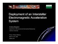
NIAC Phase I Fellows Meeting<br />
Atlanta, Georgia<br />
March 7-8, 7<br />
2006<br />
Modular Spacecraft with<br />
Integrated Structural<br />
Electrodynamic Propulsion<br />
<strong>Nestor</strong> <strong>Voronka</strong>, Robert Hoyt,<br />
Brian Gilchrist, Keith Fuhrhop<br />
TETHERS<br />
UNLIMITED,<br />
INC. NC.<br />
11807 N. Creek Pkwy S., Suite B-102B<br />
Bothell, WA 98011<br />
(425) 486-0100 Fax: (425) 482-9670<br />
voronka@tethers.com
Motivation<br />
– Traditional propulsion uses propellant as reaction<br />
mass<br />
– Advantages (of reaction mass propulsion)<br />
• Can move spacecraft center of mass, readily and relatively<br />
quickly<br />
• Multiple thrusters offer independent and complete control of<br />
spacecraft (6DOF)<br />
– Disadvantages<br />
• Propellant is a finite and mission limiting resource<br />
• Propellant mass requirements increases exponentially with<br />
mission ∆V V requirements<br />
• Propellant may be a source of contamination <strong>for</strong> optics and<br />
solar panels<br />
– Are there innovative alternatives
NASA’s s Vision of Exploration<br />
– President’s s Vision Mandates NASA to “implement a<br />
sustainable and af<strong>for</strong>dable human and robotic program to<br />
explore the solar system and beyond”<br />
– Current architectures require very large total masses<br />
to be launched from Earth<br />
– Propellant mass fractions <strong>for</strong> In-situ resource<br />
utilization (ISRU) and mining based architectures are<br />
significant and costly<br />
There exists a critical need <strong>for</strong> highly efficient low-cost<br />
propulsion to assure access to space & in-space propulsion
Space Propulsion Landscape<br />
10,000 sec<br />
2,000 sec<br />
I sp<br />
Courtesy Gallimore, A., UMich
Electrodynamic Space Tether Propulsion<br />
– In-space propulsion system<br />
– PROS:<br />
• Converts electrical energy into<br />
thrust/orbital energy<br />
• Little or no consumables (propellant) are<br />
required<br />
– CONS:<br />
• Long (1-100km) 100km) flexible structures<br />
exhibit complex dynamics, especially in<br />
higher current/thrust cases<br />
• Gravity gradient tethers have constrained<br />
thrust vector<br />
• Relies on ambient plasma to close<br />
current loop
Proposed Solution<br />
– Multifunctional propulsion-and<br />
and-<br />
structure system that utilizes<br />
Lorentz <strong>for</strong>ces generated by<br />
current carrying booms to<br />
generate thrust with little or<br />
no propellant expenditure<br />
• Utilizes same principles as<br />
electrodynamic tether propulsion<br />
– Utilize relatively short (≈100(<br />
meter), rigid booms with<br />
integrated conductors capable<br />
of carrying large currents, that<br />
have plasma contactors at the<br />
ends
Per<strong>for</strong>mance of Proposed Approach<br />
– Current flowing in a moving wire through space<br />
interacts with the ambient magnetic field<br />
• Earth’s s Magnetic Field in LEO ≈ 30,000 nT<br />
• Interplanetary Magnetic Field ≈ 5 nT<br />
– Lorentz Force: F = iL x B<br />
– Space Tether Electrodynamic Propulsion<br />
• Example: 10km conductor, 1Ampere in LEO<br />
– Thrust |iLxB|<br />
iLxB| ≈ 0.3 Newtons<br />
– Proposed Integrated Structural Propulsion<br />
• Example: 100m conductor, 100 Ampere (!) in LEO<br />
– Thrust |iLxB|<br />
iLxB| ≈ 0.3 Newtons<br />
– Torque ≈ 750 N· N m
‘Structural’ ED Propulsion<br />
– By connecting six booms to a spacecraft along<br />
orthogonal axes, full 6DOF of motion can be<br />
controlled (translational and rotational)
Modular Spacecraft<br />
– By making booms and spacecraft modules<br />
modular and interconnectable, , we create self-<br />
assembling Tinkertoy ® like components <strong>for</strong><br />
space structures and systems
Optimal Path Planning<br />
• Chemical Systems near-impulsive<br />
– Hohmann and Bi-elliptical transfers<br />
• Low-thrust trajectory planning (e.g.<br />
electric propulsion)<br />
– Near continuous low level thrust<br />
– Additional constraints <strong>for</strong> optimization<br />
problem<br />
• Available Power (eclipse periods)<br />
• Tethers and Structural<br />
Electrodynamic Propulsion<br />
– Additional constraints due to ambient<br />
magnetic field<br />
• Thrust Vector direction limited<br />
• Thrust dependent on magnetic field<br />
strength!
Low-Thrust Trajectory Optimization<br />
– EP Orbit Raising from GTO to GEO<br />
• Optimizing both thrust magnitude & angle<br />
• Variable thrust can increase payload mass<br />
fraction up to 3%, and be 5-10% 5<br />
more fuel<br />
efficient<br />
– Secondary Effects to consider<br />
• J2 effects, solar eclipsing, solar cell<br />
degradation due to radiation<br />
Kimbrel, M.S., “Optimization of EP Orbit Raising”, MIT, 2002.
ESA’s SMART-1 1 Mission<br />
– Small Missions <strong>for</strong> <strong>Advanced</strong> Research in<br />
Technology - Launched on 27 Sept 2003<br />
• Arrived in lunar orbit 15 Nov 2004<br />
• PPS-1350<br />
1350-G G Hall Effect Ion Thruster (70 mNewton)<br />
– Propellant mass fraction = 82.5 kg / 370 kg = 22.3 %<br />
• 2 nd time ion propulsion used <strong>for</strong> primary propulsion<br />
– 1 st<br />
st was NASA Deep Space 1 launched Oct 1998<br />
• Utilized near-constant thrust<br />
• Trajectory optimization<br />
– Propellant consumption<br />
– Radiation Belt Transit Time<br />
– Available power (limited thrust duration during eclipse)<br />
• Thruster 1190W max out of available 1850W BOL
– Nodes<br />
• Energy Storage<br />
• System Control<br />
– Booms<br />
System Elements<br />
• Structural Propulsion Booms<br />
• Plasma Contactors<br />
• Docking Mechanisms and<br />
Sensors<br />
– Key Elements<br />
• Energy Source (Solar)<br />
• Energy Storage<br />
• Electron and Ion Sources
Energy Storage Technologies<br />
Battery Systems<br />
– NiH2<br />
• 35 – 55 cell whr/kg<br />
• 20 – 300 A-hr A<br />
ampacity<br />
• 30% DOD <strong>for</strong> LEO<br />
• 5 – 7 Year LEO life<br />
• 5 – 10 whr/kg system SE<br />
– Li Expectations<br />
• 70 – 150 Cell whr/kg<br />
• 20 – 60 A-hr A<br />
ampacity<br />
• 10 – 15% DOD <strong>for</strong> LEO<br />
• 5 – 7 Year LEO life<br />
• 10– 30 whr/kg system SE<br />
Flywheel Systems<br />
– Near Term<br />
• 25 – 40 whr/kg<br />
• >4 kW hrs capacity<br />
• 90% DOD <strong>for</strong> LEO<br />
• 15 Year LEO life<br />
• 10 – 20 whr/kg system SE<br />
– Far Term<br />
• 50 – 75 whr/kg<br />
• Unlimited thru paralleling<br />
• 90% DOD <strong>for</strong> LEO<br />
• > 15 Year LEO life<br />
• 40 – 75 whr/kg system SE<br />
Courtesy NASA GRC P&PO
Flywheel Technology Challenges and Goals<br />
Auxiliary Bearings –<br />
touchdown and launch loads,<br />
stability, caging<br />
Magnetic Bearings – low<br />
losses, higher speeds,<br />
sensors, dynamic control<br />
The Ultimate Spacecraft Battery<br />
Motor/Generator – low losses,<br />
higher speeds, drive controls<br />
Housing – system and<br />
component integration,<br />
structural/dynamic<br />
response<br />
Composite Rotor – long life,<br />
safety without containment,<br />
light-weight hubs, design and<br />
cert. standards<br />
– High System Specific Energy, Specific Power, Long Life<br />
– High Round (Charge/Discharge) Trip Efficiency<br />
– Multiple Functionality (Power and Torque)<br />
– Long Storage Life Without Degradation<br />
Far Term Goals<br />
– Integrated<br />
Power &<br />
Attitude Systems<br />
• 75 whr/kg<br />
• 92% efficiency<br />
• 25 year LEO life<br />
• -55-220°C<br />
– Energy Storage<br />
• 100 whr/kg<br />
• 30 year life<br />
– Pulse Power<br />
• 2,000 W/kg<br />
Courtesy NASA GRC P&PO
Flywheel Benefits<br />
– Life is virtually independent of Depth of Discharge<br />
– Per<strong>for</strong>ms equally well with low- and high-power loads<br />
– State of charge easily determined by measuring flywheels<br />
rotational velocity<br />
– Demonstrated net (charge/discharge) efficiencies up to 93.7%<br />
• Eddy-current and hysteresis losses in magnetic bearings and motor-<br />
generator<br />
– Two counter-rotating rotating flywheels produce no net torque (OR<br />
can be used <strong>for</strong> attitude control)<br />
!
Integrated Structural ED Boom<br />
– Requirements<br />
• Rigidity based on Application<br />
• Conductive Element(s)<br />
– Boom (Tether) Optimization<br />
• Goal: Maximize Efficiency of Power<br />
to Orbital Energy Conversion<br />
– There is no optimal tether length, nor<br />
optimal current level <strong>for</strong> a desired<br />
thrust <strong>for</strong>ce<br />
– Resistive Losses in boom (tether)<br />
should be minimized
Integrated Structural ED Boom Construction<br />
– Tensegrity (tensile integrity)<br />
Structures<br />
• “an assemblage of tension and compression components arranged in a<br />
discontinuous compression system..” R.B. Fuller Patent, 1962.<br />
– Tubular Booms (e.g. Stem)<br />
– Rigidized Inflatables<br />
• Foam Rigidized<br />
• Mechanically Rigidized<br />
• UV Cured Thermoset Composites<br />
• Thermally Cured Thermoset Composites<br />
• Work Hardened Aluminum Laminates<br />
– On-orbit Construction<br />
strength<br />
and<br />
conductive<br />
elements<br />
UV<br />
dissolving<br />
film
– Field Emissive Cathodes<br />
Electron Emitters<br />
• Microfabricated Emitter tips rely on sharp emitter<br />
tips, and close non-intercepting electrodes to<br />
generate high field required to enable electrons to<br />
quantum tunnel out of the material into space<br />
• High current densities (5000A/cm 2 ) have been<br />
demonstrated<br />
• Development undergoing to increase total current<br />
output and reduce environmental constraints<br />
– Hollow Cathodes<br />
• Electric discharge ionizes neutral gas<br />
• Technology well developed – neutralizers <strong>for</strong> EP<br />
• 100A HCs have been tested (9-40sccm<br />
Xe flow)<br />
– Annual fuel requirement <strong>for</strong> 100A @ 20 sccm<br />
• Xenon – 61.6 kg<br />
• Hydrogen – 0.47 kg<br />
• High current -> > High temperature -> > lifetime limit
Device<br />
Thermionic<br />
Cathode+Gun<br />
Field Emission<br />
Array<br />
Electron Emitter Summary<br />
Power Required<br />
Details<br />
2.1 MW 18 emitters, V f
– Passive Electron Collection<br />
Electron Collection<br />
• Space Tethers typically utilize large<br />
collection areas<br />
– Solid or grid spheres, bare tethers<br />
• To collect 100A, 46.6kV needed<br />
(4.7 MW) <strong>for</strong> a 1 meter sphere (!)<br />
– Hollow Cathode<br />
• 6.2 kW @ 280 sccm to collect<br />
100A of electrons<br />
– 6.6 kg of Hydrogen <strong>for</strong> 1 year
Hollow Cathode Ion Source<br />
– Hollow cathode Ion Emission<br />
• VERY inefficient as compared to electron emission<br />
(ionization efficiency is 1:1)<br />
• Ion emission requires ≈ 14 sccm /Ampere of emission<br />
– Annual fuel requirement <strong>for</strong> 100A @ 1440 sccm<br />
• Xenon – 4400 kg (!)<br />
• Hydrogen – 33 kg<br />
• 4.7kW @ 1440 sccm to emit 100A of ions<br />
– OPTION: Combo plan – ion thruster<br />
(without neutralizer) as contactor/thruster
Liquid Metal Ion Source<br />
– Micro Ion Source Technology – Liquid Metal Ion<br />
• Scalable system, including a passive material supply (no valves)<br />
• Goal: Wide range of ion currents from addressable large area arrays<br />
ays<br />
• Goal: Optimized Power (> 80%) and Mass (≈100%)(<br />
efficiencies<br />
• Power efficiencies on the order of 300 Watts/Ampere expected<br />
• Controllable current over 7 orders of magnitude<br />
• Development Objectives:<br />
– 2006 – 100 mA/cm 2 density, with 1mA-10mA 10mA total current<br />
– 2015 – 10A/cm 2 density, with >10A total current<br />
High Current Liquid Metal Ions<br />
(under development)<br />
Low Current Gas Ions<br />
Classical<br />
Field<br />
Ion Emission<br />
(a wetted<br />
needle)<br />
+ +<br />
_<br />
Microfabricated<br />
Capillary<br />
Architecture<br />
Electric field and surface tension<br />
balance to <strong>for</strong>m a “Taylor cone” at<br />
liquid surface<br />
+ +<br />
Liquid Metal<br />
Reservoir<br />
Accelerating Grid<br />
Extracting Electrode<br />
Simple physics of<br />
field ionization and<br />
Taylor cones<br />
No energy loss, only ionization energy<br />
Less contamination, can only produce ions<br />
Increased reliability from lower voltage<br />
operation, reduced arcing
Applications<br />
– Self-Assembling Modular Spacecraft (SAMS)<br />
– Self-Assembling Structure <strong>for</strong> Refueling Station<br />
– Self-Assembling Space Tug<br />
– Self-Assembling Structure <strong>for</strong> Large Mirror<br />
or Antenna Arrays<br />
– Formation Flying Space Systems<br />
• Terrestrial Planet Finder (TPF)
Summary<br />
– Proposed Concept IS feasible<br />
• Almost propellantless – required consumable <strong>for</strong> ion source<br />
• Almost full 6DOF control – no thrust in B-field B<br />
direction<br />
• Competitive with tradition Electric Propulsion with added benefit t of<br />
structural elements<br />
– Technology Challenges<br />
• High Current Plasma Contactors<br />
– Devices exist – robust units with higher efficiencies needed<br />
• Plasma Contactor Space Charge Limiting<br />
– High current densities may be environmentally limited<br />
• Collision proof coordinated control laws <strong>for</strong> <strong>for</strong>mation flight, and a<br />
self-assembly<br />
– Additional constraints imposed on low-thrust control laws<br />
– Potential Applications<br />
• Space Tug and Commodity Depot<br />
• Structure <strong>for</strong> Beamed Power Solar Array/Antenna Fields<br />
• Structure <strong>for</strong> Space Habitats with Integral Drag Makeup