Porsche 987 PCM 2.1 Navigation Retrofit - Maxspeed-Motorsports
Porsche 987 PCM 2.1 Navigation Retrofit - Maxspeed-Motorsports
Porsche 987 PCM 2.1 Navigation Retrofit - Maxspeed-Motorsports

You also want an ePaper? Increase the reach of your titles
YUMPU automatically turns print PDFs into web optimized ePapers that Google loves.
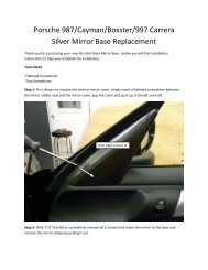
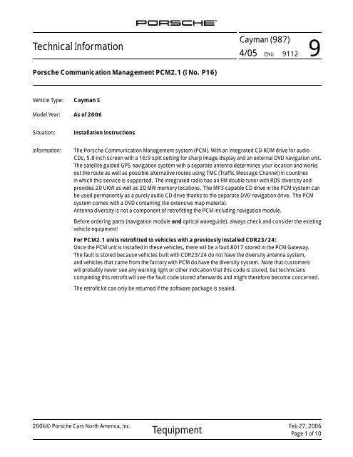
Technical Information<br />
<strong>Porsche</strong> Communication Management <strong>PCM</strong><strong>2.1</strong> (I No. P16)<br />
Vehicle Type: Cayman S<br />
Model Year: As of 2006<br />
Situation: Installation Instructions<br />
Cayman (<strong>987</strong>)<br />
4/05 ENU 9112 9<br />
Information: The <strong>Porsche</strong> Communication Management system (<strong>PCM</strong>). With an integrated CD-ROM drive for audio<br />
CDs, 5.8-inch screen with a 16:9 split setting for sharp image display and an external DVD navigation unit.<br />
The satellite-guided GPS navigation system with a separate antenna determines your location and works<br />
out the route as well as possible alternative routes using TMC (Traffic Message Channel) in countries<br />
in which this service is supported. The integrated radio has an FM double tuner with RDS diversity and<br />
provides 20 UKW as well as 20 MW memory locations. The MP3-capable CD drive in the <strong>PCM</strong> system can<br />
be used permanently as a purely audio CD drive thanks to the separate DVD navigation drive. The <strong>PCM</strong><br />
system comes with a DVD containing the extensive map material.<br />
Antenna diversity is not a component of retrofitting the <strong>PCM</strong> including navigation module.<br />
Before ordering parts (navigation module and optical waveguide), always check and consider the existing<br />
vehicle equipment!<br />
For <strong>PCM</strong><strong>2.1</strong> units retrofitted to vehicles with a previously installed CDR23/24:<br />
Once the <strong>PCM</strong> unit is installed in these vehicles, there will be a fault 8017 stored in the <strong>PCM</strong> Gateway.<br />
The fault is stored because vehicles built with CDR23/24 do not have the diversity antenna system,<br />
and vehicles that came from the factory with <strong>PCM</strong> do have the diversity system. Note that customers<br />
will probably never see any warning light or other indication that this code is stored, but technicians<br />
completing this retrofit will see the fault code stored afterwards and might therefore become concerned.<br />
The retrofit kit can only be returned if the software package is sealed.<br />
2006© <strong>Porsche</strong> Cars North America, Inc.<br />
Tequipment<br />
Feb 27, 2006<br />
Page 1 of 10
Cayman (<strong>987</strong>)<br />
9 9112 ENU 4/05<br />
Parts Info: <strong>987</strong>.044.900.72 ⇒ <strong>PCM</strong> <strong>2.1</strong> including navigation module<br />
Feb 27, 2006<br />
Page 2 of 10<br />
Only for vehicles without BOSE Surround sound system (I No. 680):<br />
997.622.707.00 1x ⇒ Optical waveguide, without CD changer<br />
997.622.715.00 1x ⇒ Optical waveguide, with CD changer<br />
Only for vehicles with BOSE Surround sound system (I No. 680):<br />
997.622.710.00 1x ⇒ Optical waveguide, without CD changer<br />
997.622.713.00 1x ⇒ Optical waveguide, with CD changer<br />
Tequipment<br />
Technical Information<br />
2006© <strong>Porsche</strong> Cars North America, Inc.
Technical Information<br />
Parts List:<br />
Figure 2<br />
Cayman (<strong>987</strong>)<br />
4/05 ENU 9112 9<br />
997.64<strong>2.1</strong>37.02 1 x ⇒ <strong>Navigation</strong> unit ⇒ Figure 2 -A-<br />
997.64<strong>2.1</strong>05.00 1 x ⇒ GPS antenna ⇒ Figure 2 -B-<br />
999.507.441.02 1 x ⇒ Speed nut ⇒ Figure 2 -C-<br />
999.073.210.00 1 x ⇒ Tapping screw ⇒ Figure 2 -D-<br />
997.642.231.00 1 x ⇒ <strong>Navigation</strong> unit holder ⇒ Figure 2 -E-<br />
997.642.342.01 4 x ⇒ Retaining clip ⇒ Figure 2 -F-<br />
000.044.900.89 1 x ⇒ DVD ROM for <strong>PCM</strong> navigation (not shown)<br />
997.612.331.00 1 x ⇒ Wire harness,⇒ Figure 2 -H- consisting of: electric wire harness<br />
and GPS antenna line<br />
999.513.051.40 20 x ⇒ Tie-wraps (not shown)<br />
997.64<strong>2.1</strong>41.03 FMH 1 x ⇒ <strong>PCM</strong> <strong>2.1</strong> (not shown)<br />
Note: The operating instructions and Quick Reference Guides for the <strong>PCM</strong> are not included in the scope of<br />
delivery and must be ordered separately.<br />
Order No.: WKD 951 321 06 <strong>PCM</strong> Operating Instructions in USA/Canadian English<br />
WKD 951 221 06 <strong>PCM</strong> Quick Reference Guide in USA/Canadian English<br />
Material: 000.043.204.82 1 x ⇒ Adhesive compound<br />
——— —— Electricaltape,fabrictape<br />
Tools: Combination wrench, 7/10 mm<br />
3/8" Ratchet with extension<br />
2006© <strong>Porsche</strong> Cars North America, Inc.<br />
Tequipment<br />
Feb 27, 2006<br />
Page 3 of 10
Cayman (<strong>987</strong>)<br />
9 9112 ENU 4/05<br />
Socket-wrench insert a/f 10/13 mm<br />
Philips screwdriver (medium)<br />
Flat screwdriver (medium)<br />
Torx wrench T20/T25/T30<br />
PIWIS Tester P 9718<br />
Plastic wedge<br />
Shop light<br />
Side cutters, needle-nose pliers<br />
Battery charger<br />
Torque wrench, signal-transmitting with ratchet NR.90<br />
Allen key, a/f 5 mm<br />
Hot-air gun<br />
Repair kit for wire harnesses NR.155-1<br />
Disassembly tool P 9570/1<br />
Work Procedure: 1 Preparatory work.<br />
Feb 27, 2006<br />
Page 4 of 10<br />
Technical Information<br />
1.1 Remove battery. ⇒ Workshop Manual ’270619 Removing and installing battery’<br />
1.2 Remove luggage compartment cover. ⇒ Workshop Manual ’703019 Removing and installing<br />
luggage compartment cover’<br />
1.3 Remove covers at the left and right close to the cowl panel. ⇒ Workshop Manual ’852219<br />
Removing and installing cover’<br />
1.4 Remove cowl panel cover. ⇒ Workshop Manual ’508719 Removing and installing cover’<br />
1.5 Only for vehicles with a telephone:<br />
Remove radio antenna (telephone) from cowl panel cover. ⇒ Workshop Manual ’914719<br />
Removing and installing radio antenna’<br />
2 Install GPS antenna. ⇒ Workshop Manual ’911319 Removing and installing GPS antenna’<br />
<strong>2.1</strong> Insert speed nut (999.507.441.02) in cowl panel.<br />
2.2 Position GPS antenna and secure with a tapping screw (999.073.210.00).<br />
3 Only for vehicles with a telephone:<br />
Fit radio antenna (telephone) on cowl panel cover. ⇒ Workshop Manual ’914719 Removing and<br />
installing radio antenna’<br />
4 Install <strong>PCM</strong> display and operator control unit.<br />
Tequipment<br />
2006© <strong>Porsche</strong> Cars North America, Inc.
Technical Information<br />
ATTENTION<br />
Cayman (<strong>987</strong>)<br />
4/05 ENU 9112 9<br />
4.1 Remove “CD player” car radio. ⇒ Workshop Manual ’912419 Removing and installing "CD player"<br />
car radio - section on "Removing"’<br />
4.2 Install <strong>PCM</strong> display and operator control unit. ⇒ Workshop Manual ’911019 Removing and<br />
installing <strong>PCM</strong> display and operator control unit - section on "Installing"’<br />
5 Route GPS antenna line.<br />
5.1 Only for vehicles with carbon canister:<br />
Loosen carbon canister. ⇒ Workshop Manual ’202519 Removing and installing carbon canister’<br />
5.2 Open the locking mechanism for the plug socket and remove plug socket from the GPS antenna<br />
cable.<br />
5.3 Loosen trim panel for luggage compartment pan on the front panel.<br />
5.4 Punch rubber grommet ⇒ Figure 4 -A- from the<br />
front panel.<br />
5.5 Route and secure GPS antenna cable ⇒ Figure 4<br />
-H- as follows:<br />
<strong>Navigation</strong> unit installation position → through<br />
rubber grommet → along wire harness → right<br />
plenum panel<br />
5.6 Fit plug socket to GPS antenna cable and close<br />
locking mechanism.<br />
Figure 4<br />
The optical waveguide can become damaged due to incorrect installation or if the requirements for handling<br />
optical waveguides are not followed.<br />
⇒ Observe the requirements for working with optical waveguides ⇒ Workshop Manual ’9772IN Optical<br />
waveguide - MOST bus’<br />
6 Route the optical waveguide.<br />
2006© <strong>Porsche</strong> Cars North America, Inc.<br />
Tequipment<br />
Feb 27, 2006<br />
Page 5 of 10
Cayman (<strong>987</strong>)<br />
9 9112 ENU 4/05<br />
Feb 27, 2006<br />
Page 6 of 10<br />
Technical Information<br />
6.1 Only for vehicles with Tire Pressure Monitoring control unit:<br />
Remove fastening screws on Tire Pressure Monitoring control unit and lay control unit to one side.<br />
⇒ Workshop Manual ’443419 Removing and installing Tire Pressure Monitoring control unit -<br />
sectionon"Removing"’<br />
6.2 Remove connection point holder.<br />
6.<strong>2.1</strong> Only for vehicles with optical waveguide<br />
component (CD changer and/or amplifier) in<br />
front luggage compartment:<br />
Disconnect optical waveguide connection point<br />
⇒ Figure 5 -B-.<br />
6.2.2 Remove connection point holder ⇒ Figure 5 -Afrom<br />
plenum panel using needle-nose pliers.<br />
6.3 Only for vehicles with optical waveguide<br />
components in the front luggage compartment:<br />
Pull off protection cap ⇒ Figure 6 -A- on optical<br />
waveguide.<br />
Tequipment<br />
Figure 5<br />
Figure 6<br />
2006© <strong>Porsche</strong> Cars North America, Inc.
Technical Information<br />
WARNING<br />
6.4 Route optical waveguide from optical waveguide<br />
connection point ⇒ Figure 7 -A- along the front<br />
panel to the navigation unit installation position ⇒<br />
Figure 7 -B- and possibly to the amplifier ⇒ Figure<br />
7 -C- or CD changer and secure at this position.<br />
6.5 Secure connection point holder to the front panel<br />
and join optical waveguide connection point.<br />
6.6 Only for vehicles with optical waveguide<br />
component:<br />
Permanently secure standard optical waveguide.<br />
This remains functionless in the vehicle.<br />
6.7 Only for vehicles with Tire Pressure Monitoring<br />
control unit:<br />
Insert Tire Pressure Monitoring control unit and<br />
tighten fastening screws. ⇒ Workshop Manual<br />
’443419 Removing and installing Tire Pressure<br />
Monitoring control unit - section on "Installing"’<br />
Risk of short circuit and fire due to work on vehicle electrical system.<br />
Cayman (<strong>987</strong>)<br />
4/05 ENU 9112 9<br />
Figure 7<br />
⇒ When working on the electrical system, the battery must always be disconnected and covered.<br />
⇒ Always route the electrical leads without tension and so that no chafing occurs. Secure to existing<br />
harnesses/components with tie-wraps/electrical tape.<br />
7 Connect electric wires.<br />
7.1 Preparatory work.<br />
7.2 Cut electric wire to size in accordance with the<br />
component arrangement.<br />
7.3 Connect RD/GN 1.0 2 wire (terminal 30) from<br />
retrofit kit to RD/GN 0.5 2 wire (terminal 30) for CD<br />
changer.<br />
7.3.1 Cut RD/GN 0.5 2 wire approx. 10 cm behind the<br />
connector for the CD changer wire.<br />
7.3.2 Strip both ends of RD/GN 0.5 2 wire from the CD<br />
changer and end of RD/GN 1.0 2 wire from the<br />
retrofit kit.<br />
7.3.3 Slide shrink-fit hose over RD/GN 0.5 2 wire from the CD changer.<br />
2006© <strong>Porsche</strong> Cars North America, Inc.<br />
Tequipment<br />
Figure 8<br />
Feb 27, 2006<br />
Page 7 of 10
Cayman (<strong>987</strong>)<br />
9 9112 ENU 4/05<br />
Feb 27, 2006<br />
Page 8 of 10<br />
Technical Information<br />
7.3.4 Crimp both RD/GN 0.5 2 wires and RD/GN 1.0 2 wire together as a splice using a cable<br />
connection.<br />
7.3.5 Slide shrink-fit hose over the cable connection and shrink the hose with a hot-air gun. ⇒ Figure<br />
8 -A-<br />
7.4 Connect WH/RD 0.35 2 wire (Wake Up) to WH/RD 0.35 2 wire (Wake Up) from CD changer as<br />
described in Step 8.3.<br />
7.5 Connect BN 0.5 2 wire (terminal 31) to BN 0.5 2 wire (terminal 31) from CD changer as described<br />
in Step 8.3.<br />
7.6 Wrap electrical tape around wire harness.<br />
8 Complete the vehicle.<br />
8.1 In the front luggage compartment:<br />
Guide optical waveguide and antenna cable through the trim panel for the luggage compartment<br />
pan and secure trim panel for luggage compartment pan at the front panel.<br />
Note<br />
The navigation unit is located next to or on the CD changer, depending on the equipment I No.<br />
8.2 Secure navigation unit. ⇒ Workshop Manual ’911219 Removing and installing navigation unit’<br />
8.<strong>2.1</strong> Fit retaining clips (997.642.342.01) into the retaining frame and slide the navigation unit into<br />
the retaining frame until the navigation unit engages securely.<br />
8.2.2 Insert electric connectors, optical waveguide and antenna cable until the connectors engage<br />
securely.<br />
8.2.3 Position the navigation unit with retaining frame on the body, slide it into the holder, and check<br />
for secure fit.<br />
8.3 Seal rubber grommet with adhesive compound.<br />
8.4 Only for vehicles with carbon canister:<br />
Secure carbon canister. ⇒ Workshop Manual ’202519 Removing and installing carbon canister -<br />
section on "Installing"’<br />
8.5 Install luggage compartment cover. ⇒ Workshop Manual ’703019 Removing and installing<br />
luggage compartment cover – section on "Installing"’<br />
8.6 Install cowl panel cover. ⇒ Workshop Manual ’508719 Removing and installing cover – section on<br />
"Installing"’<br />
8.7 Install covers at the left and right close to the cowl panel. ⇒ Workshop Manual ’852219<br />
Removing and installing cover - section on "Installing"’<br />
8.8 Install battery. ⇒ Workshop Manual ’270619 Removing and installing battery – section on<br />
"Installing"’<br />
Tequipment<br />
2006© <strong>Porsche</strong> Cars North America, Inc.
Technical Information<br />
WARNING<br />
8.9 Connect battery charger.<br />
Sudden voltage interruption of the power supply to the control module.<br />
• Destruction of the control module.<br />
Cayman (<strong>987</strong>)<br />
4/05 ENU 9112 9<br />
⇒ During programming, it is essential to guarantee the power supply for the PIWIS Tester. It is essential to<br />
connect a battery charger with a current rating of at least 40 A to the vehicle battery.<br />
⇒ Prior to disconnecting the control module, switch off the ignition and remove the ignition key.<br />
Note<br />
The PIWIS Tester 9718 instructions take precedence and in the event of a discrepancy these are the<br />
instructions that must be followed. Deviations may occur with later software versions.<br />
The procedure described here has been structured in general terms; different text or additions may<br />
appear in the PIWIS Tester 9718 .<br />
9 Activate control units following installation.<br />
9.1 PIWIS Tester P 9718 must be switched on and connected to the vehicle.<br />
9.2 In the start-up screen of the PIWIS Offline Client, call up the "Diagnostics" menu and select the<br />
vehicle type.<br />
9.3 Select the "Special functions" menu item.<br />
9.4 Select the “Vehicle handover” test step and confirm your selection by pressing •F8“.<br />
10 Code <strong>PCM</strong> <strong>2.1</strong> and navigation unit using the PIWIS Tester P 9718 . ⇒ Workshop Manual ’911019<br />
Removing and installing <strong>PCM</strong> display and operator control unit - section on "Programming"’<br />
10.1 Select and code vehicle and "Instrument cluster" control unit.<br />
10.2 Select and code vehicle and "Gateway" control unit.<br />
10.3 Select and code "<strong>PCM</strong><strong>2.1</strong> MMI" control unit.<br />
10.4 Select and code "<strong>PCM</strong> gateway" control unit.<br />
10.5 Select and code “<strong>Navigation</strong>” control unit. ⇒ Workshop Manual ’911219 Removing and installing<br />
navigation unit - section on "Coding"’<br />
10.6 After programming is complete, read out the fault memory of all systems, correct any existing<br />
faults, and erase the fault memory.<br />
11 Disconnect battery charger, clip in battery cover and close lid.<br />
2006© <strong>Porsche</strong> Cars North America, Inc.<br />
Tequipment<br />
Feb 27, 2006<br />
Page 9 of 10
Cayman (<strong>987</strong>)<br />
9 9112 ENU 4/05<br />
12 Perform function test during test drive.<br />
Working Time: 91 12 23 00: Installing navigation module including <strong>PCM</strong><strong>2.1</strong><br />
Includes: Installing GPS antenna, navigation unit and corresponding<br />
wires, coding control units, reading out fault memories and<br />
erasing them if necessary.<br />
Without: Test drive, waiting times for satellite reception during calibration.<br />
Performing function test during test drive. Loosening<br />
and securing carbon canister.<br />
Technical Information<br />
References: ⇒ Workshop Manual ’202519 Removing and installing carbon canister’<br />
⇒ Workshop Manual ’270619 Removing and installing battery’<br />
⇒ Workshop Manual ’443419 Removing and installing Tire Pressure Monitoring control unit’<br />
⇒ Workshop Manual ’508719 Removing and installing cover’<br />
⇒ Workshop Manual ’852219 Removing and installing cover’<br />
⇒ Workshop Manual ’911019 Removing and installing <strong>PCM</strong> display and operator control unit’<br />
⇒ Workshop Manual ’911219 Removing and installing navigation unit’<br />
⇒ Workshop Manual ’911319 Removing and installing GPS antenna’<br />
⇒ Workshop Manual ’912419 Removing and installing "CD player" car radio’<br />
⇒ Workshop Manual ’914719 Removing and installing radio antenna’<br />
Labor time: 230 TU<br />
Important Notice: <strong>Porsche</strong> Cars N.A Technical Bulletins are intended for use by professional technicians, not a "Do-it-yourselfer." They are written to inform these technicians of conditions that may<br />
occur on some vehicles, or to provide information that could assist in the proper service of a vehicle. Special tools may be required to perform certain operations identified in these bulletins. Use of tools<br />
and procedures other than those recommended in these bulletins may be detrimental to the safe operation of your vehicle. Properly trained technicians have the equipment, tools, safety instructions<br />
and know-how to do a job properly and safely. If a condition is described, do not assume that the bulletin applies to your vehicle, or that your vehicle will have that condition. See your <strong>Porsche</strong> Dealer for<br />
information on whether your vehicle may benefit from the information. Part numbers listed in these bulletins are for reference only. Always check with your authorized <strong>Porsche</strong> dealer to verify correct part<br />
numbers.<br />
© <strong>Porsche</strong> Cars North America, Inc.<br />
Dealership<br />
Distribution<br />
Routing<br />
Service Manager<br />
Asst. Manager<br />
_______<br />
_______<br />
Shop Foreman<br />
Warranty Admin.<br />
_______<br />
_______<br />
Service Technician<br />
Service Technician<br />
________<br />
________<br />
Dr. Ing. h.c. F. <strong>Porsche</strong> AG is the owner of numerous trademarks, both registered and unregistered, including without limitation the <strong>Porsche</strong> Crest®, <strong>Porsche</strong>®, Boxster®, Carrera®, Cayenne®,<br />
Cayman®, Tiptronic®, VarioCam®, <strong>PCM</strong>®, 911®, 4S®, and the model numbers and distinctive shapes of <strong>Porsche</strong>’s automobiles such as, the federally registered 911 automobile. The third party<br />
trademarks contained herein are the properties of their respective owners. <strong>Porsche</strong> Cars North America, Inc., believes the specifications to be correct at the time of printing. However, specifications,<br />
standard equipment and options are subject to change without notice.<br />
Printed in the USA<br />
Feb 27, 2006<br />
Page 10 of 10<br />
Tequipment<br />
_______<br />
_______<br />
_______<br />
_______<br />
_______<br />
_______<br />
2006© <strong>Porsche</strong> Cars North America, Inc.