flasher stm8.pdf - SEGGER Microcontroller
flasher stm8.pdf - SEGGER Microcontroller
flasher stm8.pdf - SEGGER Microcontroller

Create successful ePaper yourself
Turn your PDF publications into a flip-book with our unique Google optimized e-Paper software.
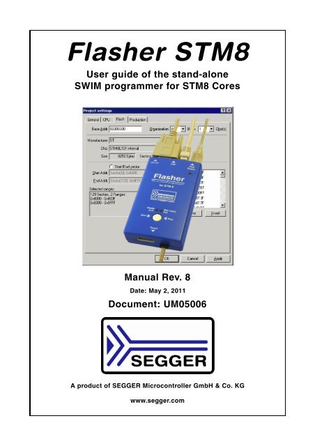
Flasher STM8<br />
User guide of the stand-alone<br />
SWIM programmer for STM8 Cores<br />
Manual Rev. 8<br />
Date: May 2, 2011<br />
Document: UM05006<br />
A product of <strong>SEGGER</strong> <strong>Microcontroller</strong> GmbH & Co. KG<br />
www.segger.com
2<br />
Disclaimer<br />
Specifications written in this document are believed to be accurate, but are not guaranteed<br />
to be entirely free of error. The information in this manual is subject to<br />
change for functional or performance improvements without notice. Please make sure<br />
your manual is the latest edition. While the information herein is assumed to be<br />
accurate, <strong>SEGGER</strong> <strong>Microcontroller</strong> GmbH & Co. KG (the manufacturer) assumes no<br />
responsibility for any errors or omissions. The manufacturer makes and you receive<br />
no warranties or conditions, express, implied, statutory or in any communication with<br />
you. The manufacturer specifically disclaims any implied warranty of merchantability<br />
or fitness for a particular purpose.<br />
Copyright notice<br />
You may not extract portions of this manual or modify the PDF file in any way without<br />
the prior written permission of the manufacturer. The software described in this document<br />
is furnished under a license and may only be used or copied in accordance<br />
with the terms of such a license.<br />
© 2011 <strong>SEGGER</strong> <strong>Microcontroller</strong> GmbH & Co. KG, Hilden / Germany<br />
Trademarks<br />
Names mentioned in this manual may be trademarks of their respective companies.<br />
Brand and product names are trademarks or registered trademarks of their respective<br />
holders.<br />
Contact address<br />
<strong>SEGGER</strong> <strong>Microcontroller</strong> GmbH & Co. KG<br />
In den Weiden 11<br />
D-40721 Hilden<br />
Germany<br />
Tel.+49 2103-2878-0<br />
Fax.+49 2103-2878-28<br />
Email: support@segger.com<br />
Internet: http://www.segger.com<br />
Flasher STM8 (UM05006) © 2011 <strong>SEGGER</strong> <strong>Microcontroller</strong> GmbH & Co. KG
Revisions<br />
This manual describes the Flasher STM8 device.<br />
For further information on topics or routines not yet specified, please contact us.<br />
Revision Date By Explanation<br />
8 110502 OO<br />
Chapter "Hardware":<br />
- Some minor changes.<br />
- Added more detailed information about the connection<br />
cable.<br />
7 110307 OO<br />
Chapter "Introduction":<br />
- Added speed measurements<br />
Chapter "Working with Flasher STM8":<br />
6 101007 OO<br />
- Added example for setting up multiple configurations<br />
for stand-alone mode and how to switch<br />
between configurations remotely.<br />
5 100702 OO<br />
Chapter "Remote control":<br />
- Added information regarding TCP/IP terminal<br />
Updated document to renamed binaries in Flasher<br />
4 100624 OO STM8 software and documentation package.<br />
Updated all screenshots.<br />
Chapter "Hardware":<br />
3 100607 OO<br />
- Added information about connecting Flasher GND<br />
to power supply ground for more power stabilization<br />
Chapter "Hardware":<br />
2 100525 OO<br />
- Added more information to SWIM and Reset output<br />
signals<br />
- Some minor changes<br />
Chapter "Working with Flasher STM8":<br />
- Added information about setup multiple Flasher<br />
1 100401 OO on one PC<br />
Chapter "Hardware":<br />
- Declared 10-pin connector as obsolete interface<br />
0 091210 OO Initial version.<br />
Flasher STM8 (UM05006) © 2011 <strong>SEGGER</strong> <strong>Microcontroller</strong> GmbH & Co. KG<br />
3
4<br />
Flasher STM8 (UM05006) © 2011 <strong>SEGGER</strong> <strong>Microcontroller</strong> GmbH & Co. KG
About this document<br />
This document describes the Flasher STM8. It provides an overview over the major<br />
features of the Flasher STM8, gives you some background information about SWIM,<br />
STM8 general and describes Flasher STM8 related software packages available from<br />
Segger. Finally, the chapter Support and FAQs on page 65 helps to troubleshoot common<br />
problems.<br />
Typographic conventions<br />
This manual uses the following typographic conventions:<br />
Style Used for<br />
Body Body text.<br />
Keyword<br />
Text that you enter at the command-prompt or that appears on the<br />
display (that is system functions, file- or pathnames).<br />
Reference Reference to chapters, tables and figures or other documents.<br />
GUIElement Buttons, dialog boxes, menu names, menu commands.<br />
Table 1.1: Typographic conventions<br />
Flasher STM8 (UM05006) © 2011 <strong>SEGGER</strong> <strong>Microcontroller</strong> GmbH & Co. KG<br />
5
6<br />
<strong>SEGGER</strong> <strong>Microcontroller</strong> GmbH & Co. KG develops<br />
and distributes software development tools and ANSI<br />
C software components (middleware) for embedded<br />
systems in several industries such as telecom, medical<br />
technology, consumer electronics, automotive<br />
industry and industrial automation.<br />
<strong>SEGGER</strong>’s intention is to cut software developmenttime<br />
for embedded applications by offering compact flexible and easy to use middleware,<br />
allowing developers to concentrate on their application.<br />
Our most popular products are emWin, a universal graphic software package for embedded<br />
applications, and embOS, a small yet efficient real-time kernel. emWin, written<br />
entirely in ANSI C, can easily be used on any CPU and most any display. It is complemented<br />
by the available PC tools: Bitmap Converter, Font Converter, Simulator and<br />
Viewer. embOS supports most 8/16/32-bit CPUs. Its small memory footprint makes it<br />
suitable for single-chip applications.<br />
Apart from its main focus on software tools, <strong>SEGGER</strong> develops and produces programming<br />
tools for flash microcontrollers, as well as J-Link, a JTAG emulator to assist in development,<br />
debugging and production, which has rapidly become the industry standard for<br />
debug access to ARM cores.<br />
Corporate Office:<br />
http://www.segger.com<br />
EMBEDDED SOFTWARE<br />
(Middleware)<br />
emWin<br />
Graphics software and GUI<br />
emWin is designed to provide an efficient,<br />
processor- and display controller-independent<br />
graphical user<br />
interface (GUI) for any application that<br />
operates with a graphical display.<br />
Starterkits, eval- and trial-versions are<br />
available.<br />
embOS<br />
Real Time Operating System<br />
embOS is an RTOS designed to offer<br />
the benefits of a complete multitasking<br />
system for hard real time applications<br />
with minimal resources. The profiling<br />
PC tool embOSView is included.<br />
emFile<br />
File system<br />
emFile is an embedded file system with<br />
FAT12, FAT16 and FAT32 support.<br />
emFile has been optimized for minimum<br />
memory consumption in RAM and<br />
ROM while maintaining high speed.<br />
Various Device drivers, e.g. for NAND<br />
and NOR flashes, SD/MMC and CompactFlash<br />
cards, are available.<br />
emUSB<br />
USB device stack<br />
A USB stack designed to work on any<br />
embedded system with a USB client<br />
controller. Bulk communication and<br />
most standard device classes are supported.<br />
United States Office:<br />
http://www.segger-us.com<br />
<strong>SEGGER</strong> TOOLS<br />
Flasher<br />
Flash programmer<br />
Flash Programming tool primarily for microcontrollers.<br />
J-Link<br />
JTAG emulator for ARM cores<br />
USB driven JTAG interface for ARM cores.<br />
J-Trace<br />
JTAG emulator with trace<br />
USB driven JTAG interface for ARM cores with<br />
Trace memory. supporting the ARM ETM (Embedded<br />
Trace Macrocell).<br />
J-Link / J-Trace Related Software<br />
Add-on software to be used with <strong>SEGGER</strong>’s industry<br />
standard JTAG emulator, this includes flash<br />
programming software and flash breakpoints.<br />
Flasher STM8 (UM05006) © 2011 <strong>SEGGER</strong> <strong>Microcontroller</strong> GmbH & Co. KG
7<br />
Table of Contents<br />
1 Introduction ......................................................................................................................9<br />
1.1 Flasher STM8 overview.............................................................................10<br />
1.1.1 Features of Flasher STM8..........................................................................10<br />
1.1.2 Working environment...............................................................................10<br />
1.2 Specifications..........................................................................................11<br />
1.2.1 Specifications for Flasher STM8 .................................................................11<br />
1.3 Flasher STM8 features..............................................................................12<br />
1.4 Supported CPU cores ...............................................................................13<br />
1.5 Download speed ......................................................................................14<br />
2 Setup..............................................................................................................................15<br />
2.1 Installing the Flasher STM8 software and documentation pack .......................16<br />
2.1.1 Setup procedure......................................................................................16<br />
2.2 Setting up the USB interface .....................................................................19<br />
2.2.1 Verifying correct driver installation.............................................................19<br />
2.3 Uninstalling the J-Link USB driver ..............................................................21<br />
2.4 Setting up the IP interface ........................................................................22<br />
2.4.1 Connecting the first time ..........................................................................22<br />
2.4.2 Configuring the Flasher ............................................................................23<br />
3 Flasher STM8 related software......................................................................................27<br />
3.1 Flasher STM8 software and documentation package .....................................28<br />
3.2 Flasher STM8 software and documentation package in detail .........................29<br />
3.2.1 STM8 Commander (Command line tool)......................................................29<br />
3.2.2 Flasher STM8 Software (Program flash memory)..........................................30<br />
3.3 Using the JLinkSTM8.dll............................................................................31<br />
3.3.1 What is the JLinkSTM8.dll?........................................................................31<br />
3.3.2 Determining the version of JLinkSTM8.dll ....................................................31<br />
3.3.3 Determining which DLL is used by a program ..............................................32<br />
4 Working with Flasher STM8...........................................................................................33<br />
4.1 Operating modes .....................................................................................34<br />
4.1.1 PC mode ................................................................................................34<br />
4.1.2 Stand-alone mode ...................................................................................37<br />
4.1.3 MSD mode..............................................................................................38<br />
4.2 Multiple File Support ................................................................................39<br />
4.2.1 Setting up configurations and switching configurations .................................40<br />
4.3 Connecting multiple Flasher to your PC.......................................................44<br />
4.3.1 How does it work? ...................................................................................44<br />
4.3.2 Configuring multiple Flasher STM8 .............................................................45<br />
4.3.3 Connecting to a Flasher with non default USB-Address..................................46<br />
5 Remote control...............................................................................................................47<br />
5.1 Overview................................................................................................48<br />
5.2 Handshake control ...................................................................................49<br />
5.3 ASCII command interface .........................................................................50<br />
5.3.1 Introduction............................................................................................50<br />
5.3.2 General command and reply message format ..............................................50<br />
5.3.3 Communication port settings.....................................................................50<br />
Flasher STM8 (UM05006) © 2011 <strong>SEGGER</strong> <strong>Microcontroller</strong> GmbH & Co. KG
8<br />
5.3.4 Commands to Flasher .............................................................................. 50<br />
5.3.5 Reply from Flasher STM8.......................................................................... 54<br />
6 Hardware .......................................................................................................................57<br />
6.1 10-pin connector (obsolete)...................................................................... 58<br />
6.1.1 10-pin connector pinout ........................................................................... 58<br />
6.2 4-pin Connector ...................................................................................... 59<br />
6.2.1 4-pin connector pinout............................................................................. 59<br />
6.3 Connection cable..................................................................................... 60<br />
6.4 Target board design for SWIM................................................................... 61<br />
6.4.1 Target power supply ................................................................................ 61<br />
6.5 How to determine the hardware version ..................................................... 62<br />
7 Background information .................................................................................................63<br />
7.1 Flash programming ................................................................................. 64<br />
7.1.1 How does flash programming via Flasher STM8 work ? ................................. 64<br />
7.1.2 Data download to RAM............................................................................. 64<br />
7.1.3 Available options for flash programming ..................................................... 64<br />
8 Support and FAQs .........................................................................................................65<br />
8.1 Contacting support .................................................................................. 66<br />
8.2 Frequently Asked Questions...................................................................... 67<br />
9 Glossary.........................................................................................................................69<br />
10 Literature and references.............................................................................................71<br />
Flasher STM8 (UM05006) © 2011 <strong>SEGGER</strong> <strong>Microcontroller</strong> GmbH & Co. KG
Chapter 1<br />
Introduction<br />
This chapter gives a short overview about the Flasher STM8.<br />
Flasher STM8 (UM05006) © 2011 <strong>SEGGER</strong> <strong>Microcontroller</strong> GmbH & Co. KG<br />
9
10 CHAPTER 1 Introduction<br />
1.1 Flasher STM8 overview<br />
Flasher STM8 is a programming tool for microcontrollers with on-chip Flash memory<br />
and STM8 core. Flasher STM8 is designed for programming flash targets with a PC<br />
program or stand-alone.<br />
Flasher STM8 connects via USB, via ethernet or via RS232 interface to a PC, running<br />
Microsoft Windows 2000, Windows XP, Windows 2003, Windows Vista or Windows 7.<br />
Flasher STM8 has a built-in 10-pin interface connector and a built-in 4-pin interface<br />
connector, which are compatible with the debug connectors used by STM8 eval systems.<br />
1.1.1 Features of Flasher STM8<br />
• Three boot modes: PC mode, stand-alone mode, MSD mode<br />
• Stand-alone SWIM programmer (Once set up, Flasher can be controlled without<br />
the use of PC program)<br />
• No power supply required, powered through USB<br />
• Support for all STM8 devices<br />
• 128 MB memory for storage of target program<br />
• Serial in target programming supported<br />
• Data files can be updated via PC program<br />
1.1.2 Working environment<br />
General<br />
Flasher STM8 can be operated from a PC with an appropriate software like Flasher<br />
STM8 software or in stand-alone mode.<br />
Host System<br />
IBM PC/AT or compatible. CPU: Pentium with at least 192MB of RAM, running<br />
Microsoft Windows 2000, Windows XP, Windows 2003, Windows Vista or Windows 7.<br />
It needs to have an USB, ethernet or RS232 interface available for communication<br />
with Flasher STM8.<br />
Power supply<br />
Flasher requires 5V DC, min. 100mA via USB connector. If USB is not connected, the<br />
USB connector is used to power the device. Supply voltage is the same in this case.<br />
Please avoid excess voltage.<br />
Installing Flasher STM8 PC-software Flasher STM8<br />
The latest version of the Flasher STM8 Software, which is part of the Flasher STM8<br />
software and documentation package, can be downloaded from our website: http://<br />
www.segger.com. For more information about using Flasher STM8 Software please<br />
refer to the Flasher STM8 Software User Guide which is also available for download<br />
on our website.<br />
Flasher STM8 (UM05006) © 2011 <strong>SEGGER</strong> <strong>Microcontroller</strong> GmbH & Co. KG
1.2 Specifications<br />
1.2.1 Specifications for Flasher STM8<br />
The following table gives an overview about the specifications (general, mechanical,<br />
electrical) for Flasher STM8.<br />
General<br />
Microsoft Windows 2000<br />
Microsoft Windows XP<br />
Microsoft Windows XP x64<br />
Microsoft Windows 2003<br />
Supported OS<br />
Microsoft Windows 2003 x64<br />
Microsoft Windows Vista<br />
Microsoft Windows Vista x64<br />
Windows 7<br />
Windows 7 x64<br />
Electromagnetic compatibility (EMC) EN 55022, EN 55024<br />
Operating temperature +5°C ... +60°C<br />
Storage temperature -20°C ... +65 °C<br />
Relative humidity (non-condensing) Max. 90% rH<br />
Size (without cables) 121mm x 66mm x 30mm<br />
Weight (without cables) 122g<br />
Mechanical<br />
USB interface USB 2.0, full speed<br />
Ethernet interface 100MHz full duplex<br />
RS232 Host Interface RS232 9-pin<br />
SWIM (either via 10-pin connector or 4-<br />
Target interface<br />
pin connector depending on target hardware)<br />
SWIM Interface, Electrical<br />
Power supply<br />
USB powered, 100mA for Flasher STM8.<br />
500mA if target is powered by Flasher<br />
STM8.<br />
Target interface voltage (VIF ) 1.2V ... 5V<br />
Target supply voltage 4.5V ... 5V (if powered with 5V on USB)<br />
Target supply current Max. 300mA<br />
LOW level input voltage (VIL ) Max. 40% of VIF HIGH level input voltage (VIH )<br />
Table 1.1: Flasher STM8 specifications<br />
Min. 60% of VIF Flasher STM8 (UM05006) © 2011 <strong>SEGGER</strong> <strong>Microcontroller</strong> GmbH & Co. KG<br />
11
12 CHAPTER 1 Introduction<br />
1.3 Flasher STM8 features<br />
• USB 2.0 interface<br />
• Full duplex 100Mbit ethernet interface<br />
• Any STM8 core supported<br />
• No power supply required, powered through USB<br />
• Target voltage can be measured<br />
• Fully plug and play compatible<br />
• Standard 4-pin SWIM connector<br />
• USB, ethernet, RS232 and 4-pin ribbon cable included<br />
• TCP/IP server included in Flasher STM8, which allows using Flasher via TCP/IP<br />
networks<br />
• Flash programming software available<br />
• Integrated optical isolation between host and target system<br />
• Target power supply via pin 1 of the 4-pin interface (up to 300mA to target with<br />
overload protection)<br />
Flasher STM8 (UM05006) © 2011 <strong>SEGGER</strong> <strong>Microcontroller</strong> GmbH & Co. KG
1.4 Supported CPU cores<br />
Flasher STM8 has been designed and tested with the following cores, but should work<br />
with any STM8 core. If you experience problems with a particular core, do not hesitate<br />
to contact Segger.<br />
• STM8A<br />
• STM8L<br />
• STM8S<br />
Flasher STM8 (UM05006) © 2011 <strong>SEGGER</strong> <strong>Microcontroller</strong> GmbH & Co. KG<br />
13
14 CHAPTER 1 Introduction<br />
1.5 Download speed<br />
Flasher STM8 has been designed to allow downloading to the target as fast as the<br />
target can receive and program flash. The table below shows the measured download<br />
speed for standalone programming and for programming via PC driven software. The<br />
following testing environment has been used:<br />
• PC with 2.53 GHz Core2Duo, running WinXP<br />
• USB 2.0 port<br />
• USB 2.0 hub<br />
• Flasher STM8<br />
• STM8S208MBT6B<br />
Operation Standalone mode PC mode<br />
Program (128kB) 8.5s (15kB/s) 8.5s (15kB)<br />
Program and verify (128kB)<br />
Table 1.2: Flasher STM8 download speed<br />
11.3s 11.3s<br />
Flasher STM8 (UM05006) © 2011 <strong>SEGGER</strong> <strong>Microcontroller</strong> GmbH & Co. KG
Chapter 2<br />
Setup<br />
This chapter describes the setup procedure required in order to work with Flasher<br />
STM8. Primarily this includes the installation of the Flasher STM8 software and documentation<br />
package.<br />
Flasher STM8 (UM05006) © 2011 <strong>SEGGER</strong> <strong>Microcontroller</strong> GmbH & Co. KG<br />
15
16 CHAPTER 2 Setup<br />
2.1 Installing the Flasher STM8 software and documentation<br />
pack<br />
Flasher STM8 is shipped with a bundle of applications, corresponding manuals and<br />
some sample projects and the kernel mode USB driver.<br />
Refer to chapter Flasher STM8 related software on page 27 for an overview about the<br />
Flasher STM8 software and documentation pack.<br />
2.1.1 Setup procedure<br />
To install the Flasher STM8 software and documentation pack, follow this procedure:<br />
Note: We recommend to check if a newer version of the Flasher STM8 software<br />
and documentation pack is available for download before starting the installation.<br />
Check therefore the Flasher STM8 related download section of our website.<br />
Before you plug your Flasher STM8 into your computer's USB port, extract the setup<br />
tool Setup_FlasherSTM8_V.zip. The setup wizard will install the<br />
software and documentation pack that also includes the certified J-Link USB driver.<br />
Start the setup by double clicking Setup_FlasherSTM8_V.exe. The<br />
license Agreement dialog box will be opened. Accept the terms with the Yes button.<br />
1. The Welcome dialog box is opened. Click Next > to open the Choose Destination<br />
Location dialog box.<br />
Flasher STM8 (UM05006) © 2011 <strong>SEGGER</strong> <strong>Microcontroller</strong> GmbH & Co. KG
2. Accept the default installation path C:\Program Files\SEG-<br />
GER\FlasherSTM8_V or choose an alternative location. Confirm<br />
your choice with the Next > button.<br />
3. The Choose options dialog is opened. The Create entry in start menu option<br />
is preselected. Accept or deselect the options and confirm the selection with the<br />
Next > button.<br />
Confirm start of installation by pressing Next > button again.<br />
4. The installation process will be started.<br />
Flasher STM8 (UM05006) © 2011 <strong>SEGGER</strong> <strong>Microcontroller</strong> GmbH & Co. KG<br />
17
18 CHAPTER 2 Setup<br />
5. The Installation Complete dialog box appears after the copy process. Close the<br />
installation wizard with the Finish > button.<br />
The Flasher STM8 software and documentation pack is successfully installed on<br />
your PC.<br />
6. Connect your Flasher STM8 via USB with your PC. The Flasher STM8 will be identified<br />
and after a short period the Flasher LED stops rapidly flashing and stays on<br />
permanently.<br />
Flasher STM8 (UM05006) © 2011 <strong>SEGGER</strong> <strong>Microcontroller</strong> GmbH & Co. KG
2.2 Setting up the USB interface<br />
After installing the Flasher STM8 software and documentation package it should not<br />
be necessary to perform any additional setup sequences in order to configure the<br />
USB interface of Flasher STM8.<br />
2.2.1 Verifying correct driver installation<br />
To verify the correct installation of the driver, disconnect and reconnect Flasher STM8<br />
to the USB port. During the enumeration process which takes about 2 seconds, the<br />
LED on Flasher STM8 is flashing. After successful enumeration, the LED stays on permanently.<br />
Start the provided sample application STM8Commander.exe, which should display the<br />
compilation time of the Flasher firmware, the serial number and a target voltage of<br />
0.000V. The screenshot below shows an example.<br />
In addition you can verify the driver installation by consulting the Windows device<br />
manager. If the driver is installed and your Flasher STM8 is connected to your computer,<br />
the device manager should list the J-Link USB driver as a node below "Universal<br />
Serial Bus controllers" as shown in the following screenshot:<br />
Flasher STM8 (UM05006) © 2011 <strong>SEGGER</strong> <strong>Microcontroller</strong> GmbH & Co. KG<br />
19
20 CHAPTER 2 Setup<br />
Right-click on the driver to open a context menu which contains the command Properties.<br />
If you select this command, a J-Link driver Properties dialog box is opened<br />
and should report: This device is working properly.<br />
If you experience problems, refer to the chapter Support and FAQs on page 65 for<br />
help. You can select the Driver tab for detailed information about driver provider,<br />
version, date and digital signer.<br />
Flasher STM8 (UM05006) © 2011 <strong>SEGGER</strong> <strong>Microcontroller</strong> GmbH & Co. KG
2.3 Uninstalling the J-Link USB driver<br />
If Flasher STM8 is not properly recognized by Windows and therefore does not enumerate,<br />
it makes sense to uninstall the J-Link USB driver.<br />
This might be the case when:<br />
• The LED on the Flasher STM8 is rapidly flashing.<br />
• The Flasher STM8 is recognized as Unknown Device by Windows.<br />
To have a clean system and help Windows to reinstall the J-Link driver, follow this<br />
procedure:<br />
1. Disconnect Flasher STM8 from your PC.<br />
2. Open the Add/Remove Programs dialog (Start > Settings > Control Panel<br />
> Add/Remove Programs) and select Windows Driver Package - Segger<br />
(jlink) USB and click the Change/Remove button.<br />
3. Confirm the uninstallation process.<br />
Flasher STM8 (UM05006) © 2011 <strong>SEGGER</strong> <strong>Microcontroller</strong> GmbH & Co. KG<br />
21
22 CHAPTER 2 Setup<br />
2.4 Setting up the IP interface<br />
Flasher STM8 has an additional Ethernet interface, to communicate with the host system.<br />
A built-in web server allows configuration of the <strong>flasher</strong> via web interface. In<br />
addition to that, you can set a default gateway for the <strong>flasher</strong> which allows using it<br />
even in large intranets. For simplicity the setup process of Flasher STM8 is described<br />
in this section.<br />
2.4.1 Connecting the first time<br />
When connecting Flasher the first time, it attempts to acquire an IP address via<br />
DHCP. To get information about which IP address is acquired, you have two possibilities:<br />
• Connecting Flasher via USB and via Ethernet and read out the IP address via<br />
STM8Commander.exe.<br />
• Connecting Flasher only via Ethernet and read out the IP via the DHCP IP Assignment<br />
table of your DHCP Server.<br />
In the following, both ways to get the IP address assigned to Flasher via DHCP, are<br />
explained.<br />
2.4.1.1 Connecting via USB and Ethernet<br />
When using STM8Commander.exe in order to read out the IP address, Flasher has to<br />
be connected to your host system via Ethernet and via USB. When starting<br />
STM8Commander.exe, it will show information about the IP address (static / dynamic)<br />
when connecting to Flasher.<br />
To get more detailed information about the current configuration of the Flasher (such<br />
as subnet mask and MAC address), you can use the conf command in<br />
STM8Commander.exe.<br />
After reading out the IP address you can connect to Flasher via Ethernet, using the IP<br />
address.<br />
Flasher STM8 (UM05006) © 2011 <strong>SEGGER</strong> <strong>Microcontroller</strong> GmbH & Co. KG
2.4.1.2 Connecting via Ethernet only<br />
This way of reading out the IP address of Flasher can be used for example if you do<br />
not have administrator rights on the host system in order to install the USB driver<br />
which is necessary to connect to Flasher via USB. To get the IP address which has<br />
been assigned to Flasher via DHCP, you have to read it out from the DHCP IP Assignment<br />
table of your DHCP Server:<br />
You can easily identify your Flasher by its host ID (in this case FLASHER351100023)<br />
and by its MAC addr which always starts with: 00-22-C7-03-XX-XX where XX depends<br />
on the last five digits of the serial number of your Flasher. In this case the serial<br />
number of the connected Flasher is 351100023 (0x0017), so its MAC address is: 00-<br />
22-C7-03-00-17.<br />
2.4.2 Configuring the Flasher<br />
By default, Flasher is configured to receive an IP address and a subnet mask via<br />
DHCP. It is also possible to assign a fixed IP address to it. Setting up Flasher can be<br />
done via STM8Commander.exe or via web interface. In the following, both configuration<br />
methods are described.<br />
2.4.2.1 Configuring Flasher via STM8Commander.exe<br />
Configuring Flasher via STM8Commander.exe is very simple because only one command<br />
(in different variations) is necessary to choose between automatic IP address<br />
and dynamic IP address assignment.<br />
Note: If you want to configure Flasher via STM8Commander.exe and Flasher is<br />
connected to your host-system via Ethernet only, you have to type in the ip<br />
command.<br />
Example<br />
ip 192.168.199.29<br />
Assigning an IP address via DHCP<br />
By default, Flasher is configured to acquire an IP address via DHCP, so it should not<br />
be necessary to configure this. But, if you change the IP address to a fixed one,<br />
DHCP is disabled from this point. To re-enable DHCP you should use the ipaddr DHCP<br />
command in STM8Commander.exe. The ipaddr command will be explained in the following.<br />
Flasher STM8 (UM05006) © 2011 <strong>SEGGER</strong> <strong>Microcontroller</strong> GmbH & Co. KG<br />
23
24 CHAPTER 2 Setup<br />
Assigning an IP address manually<br />
If you do not want Flasher to be configured via DHCP, you can assign an IP address<br />
and a subnet mask (optional) manually. This is done via the ipaddr command in<br />
STM8Commander.exe. This command can be used in four different ways, which are<br />
explained in the table below:<br />
Example ipaddr<br />
STM8>ipaddr<br />
DHCP assigned network configuration<br />
IP-Addr: 192.168.199.29<br />
Subnetmask: 255.255.0.0<br />
Example ipaddr <br />
Command Explanation<br />
If no additional parameter is specified, the current<br />
ipaddr<br />
IP and subnet mask of Flasher are shown.<br />
If an IP is given as an additional parameter the<br />
given IP address is set as the IP address for Flasher.<br />
ipaddr <br />
A default 16-bit subnet mask (255.255.0.0) is used.<br />
From this time Flasher uses this static IP, DHCP is<br />
disabled from this point.<br />
If an IP and a subnet mask is given as an additional<br />
parameter, the given IP and the given subnet mask<br />
ipaddr <br />
are used. From this time Flasher uses this static IP<br />
and subnet mask, DHCP is disabled from this point.<br />
If DHCP is given as an additional parameter the use<br />
ipaddr DHCP<br />
of DHCP is enabled.<br />
Previously made IP settings are discarded.<br />
Table 2.1: ipaddr command description<br />
STM8>ipaddr 192.168.87.115<br />
IP address successfully changed to '192.168.87.115'.<br />
Subnetmask successfully changed to '255.255.0.0'.<br />
Example ipaddr <br />
STM8>ipaddr 192.168.87.116 255.255.0.0<br />
IP address successfully changed to '192.168.87.116'.<br />
Subnetmask successfully changed to '255.255.0.0'.<br />
Example ipaddr DHCP<br />
STM8>ipaddr DHCP<br />
Configuration successfully changed to DHCP.<br />
Flasher STM8 (UM05006) © 2011 <strong>SEGGER</strong> <strong>Microcontroller</strong> GmbH & Co. KG
2.4.2.2 Configuring Flasher via web interface<br />
Flasher comes with a web server, which provides a web interface for configuration.<br />
This enables you to configure Flasher without additional tools, just with a simple web<br />
browser. The Home page of the web interface shows the serial number, the current<br />
IP address and the MAC address of the Flasher.<br />
The Network configuration page allows you to configure the IP address, the subnet<br />
mask and the default gateway of Flasher. You can choose between automatic IP<br />
assignment and manual IP assignment by selecting the appropriate radio button. If<br />
you choose manual, you can change the IP address, the subnet mask and the<br />
default gateway by entering the desired values in the appropriate fields and clicking<br />
change. So, you do not have to care about any command syntax in order to change<br />
the IP address/subnet mask/default gateway.<br />
Flasher STM8 (UM05006) © 2011 <strong>SEGGER</strong> <strong>Microcontroller</strong> GmbH & Co. KG<br />
25
26 CHAPTER 2 Setup<br />
Flasher STM8 (UM05006) © 2011 <strong>SEGGER</strong> <strong>Microcontroller</strong> GmbH & Co. KG
Chapter 3<br />
Flasher STM8 related software<br />
This chapter describes Segger’s Flasher STM8 related software portfolio available for<br />
use with Flasher STM8 hardware.<br />
Flasher STM8 (UM05006) © 2011 <strong>SEGGER</strong> <strong>Microcontroller</strong> GmbH & Co. KG<br />
27
28 CHAPTER 3 Flasher STM8 related software<br />
3.1 Flasher STM8 software and documentation package<br />
Flasher STM8 is shipped with a bundle of applications.<br />
Software Description<br />
JLinkSTM8.dll DLL for using Flasher STM8 with third-party programs.<br />
STM8Commander.e<br />
xe<br />
FlasherSTM8.exe<br />
Table 3.1: Flasher STM8 related software<br />
Free command-line tool with basic functionality for target analysis.<br />
Stand-alone flash programming application. For more information<br />
about Flasher STM8 Software please refer to Flasher STM8<br />
Software User’s Guide (UM05007).<br />
Flasher STM8 (UM05006) © 2011 <strong>SEGGER</strong> <strong>Microcontroller</strong> GmbH & Co. KG
3.2 Flasher STM8 software and documentation package<br />
in detail<br />
The Flasher STM8 software documentation package is shipped together with Flasher<br />
STM8 and may also be downloaded from www.segger.com.<br />
3.2.1 STM8 Commander (Command line tool)<br />
STM8 Commander (STM8Commander.exe) is a tool that can be used for verifying<br />
proper installation of the USB driver and to verify the connection to the STM8 chip, as<br />
well as for simple analysis of the target system. It permits some simple commands,<br />
such as memory dump, halt, step and go. You can get an overview of the available<br />
commands by simply using the [ENTER] key or "?".<br />
Flasher STM8 (UM05006) © 2011 <strong>SEGGER</strong> <strong>Microcontroller</strong> GmbH & Co. KG<br />
29
30 CHAPTER 3 Flasher STM8 related software<br />
3.2.2 Flasher STM8 Software (Program flash memory)<br />
Flasher STM8 is a software running on Windows 2000, Windows XP, Windows 2003,<br />
Windows Vista or Windows 7 systems and enables you to program your flash EEPROM<br />
devices via the SWIM connector on your target system.<br />
Flasher STM8 works with any STM8 system and supports the programming of internal<br />
flash of STM8 microcontrollers. It allows you to erase, fill, program, blank check,<br />
upload flash content, and view memory of your flash devices.<br />
Features<br />
• Works with any STM8 chip<br />
• STM8 microcontrollers (internal flash) supported<br />
• Smart read-back: Only non-blank portions of flash transferred and saved<br />
• Easy to use, comes with projects for standard eval boards.<br />
Flasher STM8 (UM05006) © 2011 <strong>SEGGER</strong> <strong>Microcontroller</strong> GmbH & Co. KG
3.3 Using the JLinkSTM8.dll<br />
3.3.1 What is the JLinkSTM8.dll?<br />
The JLinkSTM8.dll is a standard Windows DLL typically used from C or C++, but also<br />
Visual Basic or Delphi projects. It makes the entire functionality of the Flasher STM8<br />
available through the exported functions.<br />
The functionality includes things such as halting/running the STM8 core and reading/<br />
writing memory. Therefore, it can be used in any kind of application accessing an<br />
STM8 core.<br />
3.3.2 Determining the version of JLinkSTM8.dll<br />
To determine which version of the JLinkSTM8.dll you are facing, the DLL version can<br />
be viewed by right clicking the DLL in explorer and choosing Properties from the<br />
context menu. Click the Version tab to display information about the product version.<br />
Flasher STM8 (UM05006) © 2011 <strong>SEGGER</strong> <strong>Microcontroller</strong> GmbH & Co. KG<br />
31
32 CHAPTER 3 Flasher STM8 related software<br />
3.3.3 Determining which DLL is used by a program<br />
To verify that the program you are working with is using the DLL you expect it to use,<br />
you can investigate which DLLs are loaded by your program with tools like Sysinternals’<br />
Process Explorer. It shows you details about the DLLs, used by your program,<br />
such as manufacturer and version.<br />
Process Explorer is - at the time of writing - a free utility which can be downloaded<br />
from www.sysinternals.com.<br />
Flasher STM8 (UM05006) © 2011 <strong>SEGGER</strong> <strong>Microcontroller</strong> GmbH & Co. KG
Chapter 4<br />
Working with Flasher STM8<br />
This chapter describes functionality and how to use Flasher STM8.<br />
Flasher STM8 (UM05006) © 2011 <strong>SEGGER</strong> <strong>Microcontroller</strong> GmbH & Co. KG<br />
33
34 CHAPTER 4 Working with Flasher STM8<br />
4.1 Operating modes<br />
Flasher STM8 is able to boot in 3 different modes:<br />
• PC mode<br />
• Stand-alone mode<br />
• MSD (Mass storage device) mode<br />
If Flasher STM8 can enumerate on the USB port, Flasher STM8 boots in "PC mode".<br />
In this mode Flasher STM8 can be used as an emulator. When Flasher is powered up<br />
and Flasher STM8 cannot enumerate, the "stand-alone mode" is started. In this mode<br />
Flasher STM8 can be used as a stand-alone flash programmer. When the Start/Stop<br />
button is kept pressed when Flasher is powered, Flasher STM8 boots in "MSD mode".<br />
In this mode Flasher STM8 boots as a mass storage device.<br />
4.1.1 PC mode<br />
When you want to use Flasher STM8 for the first time you need to install the Flasher<br />
STM8 related software and documentation pack. After installation, connect Flasher<br />
STM8 to the host PC via USB.<br />
4.1.1.1 Connecting the target system<br />
Power-on sequence<br />
In general, Flasher STM8 should be powered before connecting the target device.<br />
That means you should first connect Flasher STM8 with the host system via USB /<br />
ethernet / RS232 and then power up Flasher STM8 if not already powered via USB.<br />
Flasher STM8 will boot in "PC" mode. Then connect your target device to Flasher and<br />
power up your target device.<br />
Verifying target device connection with STM8Commander.exe<br />
If the USB driver is working properly and your Flasher STM8 is connected to the host<br />
system, you may connect Flasher STM8 to your target hardware. Then start the STM8<br />
command line tool STM8Commander.exe, which should now display the normal Flasher<br />
STM8 related information and in addition to that it should report that it found an<br />
STM8 target and the target’s communication speed. The screenshot below shows the<br />
output of STM8Commander.exe.<br />
Flasher STM8 (UM05006) © 2011 <strong>SEGGER</strong> <strong>Microcontroller</strong> GmbH & Co. KG
4.1.1.2 Setting up Flasher STM8 for stand-alone mode<br />
In order to set up Flasher STM8 for the "stand-alone mode" it has to be in "PC mode".<br />
When the correct connection of Flasher STM8 to the host PC is verified start the<br />
Flasher STM8 Software. For more information about Flasher STM8 Software, refer to<br />
the Flasher STM8 Software User Guide. The Flasher STM8 related software and documentation<br />
package contains the Flasher STM8 Software. When the Flasher STM8<br />
Software is started, open an appropriate Flasher project file and an appropriate data<br />
file for the target you want to program.<br />
Flasher STM8 (UM05006) © 2011 <strong>SEGGER</strong> <strong>Microcontroller</strong> GmbH & Co. KG<br />
35
36 CHAPTER 4 Working with Flasher STM8<br />
Now, choose File->Download to programmer from the menu in order to download<br />
the target configuration as well as the data file to the Flasher STM8.<br />
Flasher STM8 (UM05006) © 2011 <strong>SEGGER</strong> <strong>Microcontroller</strong> GmbH & Co. KG
After the download, you should see in the Flasher Log window that the Flasher.cfg<br />
and the Flasher.dat files have been successfully downloaded.<br />
From now on, Flasher STM8 can be used in "stand-alone mode" for stand-alone programming.<br />
4.1.2 Stand-alone mode<br />
In order to use Flasher STM8 in "stand-alone mode", it has to be configured first, as<br />
described in Setting up Flasher STM8 for stand-alone mode on page 35. To boot<br />
Flasher STM8 in the "stand-alone mode", just power up the Flasher STM8 without<br />
connection to a PC via ethernet or USB. In the "stand-alone mode" Flasher STM8 can<br />
be used as a stand-alone flash programmer.<br />
Note: Flasher STM8 can only program the target device it was configured for. In<br />
order to program another target device, you have to reconfigure it following the<br />
steps described in Setting up Flasher STM8 for stand-alone mode on page 35.<br />
4.1.2.1 LED status indicators<br />
Progress and result of an operation is indicated by Flasher STM8’s LEDs:<br />
Status of LED Meaning<br />
GREEN, high frequency flashing (10 Hz)<br />
GREEN, after programming operation has<br />
been started<br />
Table 4.1: Flasher STM8 LEDs<br />
Enumerating Flasher STM8. This only<br />
happens before the first programming<br />
operation is performed.<br />
Connect to target and perform init<br />
sequence.<br />
Flasher STM8 (UM05006) © 2011 <strong>SEGGER</strong> <strong>Microcontroller</strong> GmbH & Co. KG<br />
37
38 CHAPTER 4 Working with Flasher STM8<br />
GREEN, slow blinking (1 Hz)<br />
Erasing/Programming/Verifying operation<br />
is in progress.<br />
GREEN Operation successful / Ready.<br />
RED<br />
Table 4.1: Flasher STM8 LEDs<br />
Operation failed.<br />
4.1.3 MSD mode<br />
Status of LED Meaning<br />
When pressing the Start/Stop button of Flasher STM8 while connecting it to the PC<br />
via USB, Flasher STM8 will boot in the "MSD mode". This mode can be used to downdate<br />
a Flasher STM8 firmware version if a firmware update did not work properly and<br />
it can be used to configure Flasher STM8 for the "stand-alone mode", without using<br />
Flasher STM8 Software. If Flasher STM8 has been configured for "stand-alone mode"<br />
before, there will be four files on the MSD, FLASHER.CFG, FLASHER.DAT, FLASHER.LOG,<br />
SERIAL.TXT.<br />
FLASHER.CFG contains the configuration settings for programming the target device<br />
and FLASHER.DAT contains the data to be programmed. FLASHER.LOG contains all logging<br />
information about the commands, performed in stand-alone mode. The<br />
SERIAL.TXT contains the serial number, which will be programmed next. Currently,<br />
Flasher STM8 Software does not support to configure Flasher STM8 for automated<br />
serial number programming.<br />
If you want to configure multiple Flasher STM8 for the same target you do not have<br />
to use Flasher STM8 Software all the time. It is also possible to copy the<br />
FLASHER.CFG and the FLASHER.DAT files from a configured Flasher STM8 to another<br />
one. To copy these files boot Flasher STM8 in "MSD mode".<br />
Flasher STM8 (UM05006) © 2011 <strong>SEGGER</strong> <strong>Microcontroller</strong> GmbH & Co. KG
4.2 Multiple File Support<br />
It is also possible to have multiple data files and config files on Flasher STM8, to<br />
make Flasher STM8 more easy to use in production environment. To choose the correct<br />
configuration file and data file pair, a FLASHER.INI file is used. This init file contains<br />
a [FILES] section which describes which configuration file and which data file<br />
should be used for programming. A sample content of a FLASHER.INI file is shown<br />
below:<br />
[FILES]<br />
DataFile = "Flasher1.dat"<br />
ConfigFile = "Flasher1.cfg"<br />
Using this method, all configuration files and data files which are used in the production<br />
have to be downloaded once only. From there on a configuration file / data file<br />
pair can be switched by simply replacing the FLASHER.INI by a new one, which contains<br />
the new descriptions for the configuration file and data file. The FLASHER.INI<br />
can be replaced in three ways:<br />
1. Boot Flasher STM8 in MSD mode in order to replace the FLASHER.INI<br />
2. If Flasher STM8 is already integrated into the production line, runs in stand-alone<br />
mode and can not be booted in other mode: Use the file I/O commands provided<br />
by the ASCII interface of Flasher STM8, to replace the FLASHER.INI. For more<br />
information about the file I/O commands, please refer to File I/O commands on<br />
page 52.<br />
3. If Flasher STM8 is already integrated into the production line and is driven via<br />
Flasher STM8 PC software: Use the file I/O commands provided by the Flasher<br />
STM8 Commander to replace the FLASHER.INI. For more information about the<br />
STM8 Commander please refer to STM8 Commander (Command line tool) on<br />
page 29.<br />
Flasher STM8 (UM05006) © 2011 <strong>SEGGER</strong> <strong>Microcontroller</strong> GmbH & Co. KG<br />
39
40 CHAPTER 4 Working with Flasher STM8<br />
4.2.1 Setting up configurations and switching configurations<br />
The following steps describe the way to setup and use multiple configurations and<br />
how they can be exchanged using the STM8 Commander. Setup and exchanging configurations<br />
can be done via RS232 the same way except that the way of file access is<br />
slightly different using the ASCII command interface as described in ASCII command<br />
interface on page 50.<br />
1. Setup your first configuration you wish to use with the Flasher using Flasher STM8<br />
Software.<br />
Flasher STM8 (UM05006) © 2011 <strong>SEGGER</strong> <strong>Microcontroller</strong> GmbH & Co. KG
2. Use "File->Save programmer configuration file..." and save as "Flasher1.cfg" to a<br />
temporary directory.<br />
3. Use "File->Save programmer data file..." and save as "Flasher1.dat" to a temporary<br />
directory.<br />
Flasher STM8 (UM05006) © 2011 <strong>SEGGER</strong> <strong>Microcontroller</strong> GmbH & Co. KG<br />
41
42 CHAPTER 4 Working with Flasher STM8<br />
4. Repeat the steps 1-3 to create an other configuration and save the files as<br />
"Flasher2.cfg" and "Flasher2.dat" to the same directory you saved the first set of<br />
configuration files.<br />
5. Create a text file named "FLASHER.ini" with the following content:<br />
[FILES]<br />
DataFile = "Flasher1.dat"<br />
ConfigFile = "Flasher1.cfg"<br />
6. The content of your temporary folder should now look like the following screenshot:<br />
Note: Steps from now on may slightly differ in command usage when using other<br />
communication channels such as RS232 ASCII interface but follow the same steps.<br />
7. Start the STM8 Commander utility.<br />
8. Delete old files on the Flasher using the "fdelete" command if you are unsure if<br />
the Flasher is empty. In the screenshot below no files were on the Flasher, therefor<br />
returning an error on these operations:<br />
Flasher STM8 (UM05006) © 2011 <strong>SEGGER</strong> <strong>Microcontroller</strong> GmbH & Co. KG
9. Download the files from your temporary folder to the Flasher using the "fwrite"<br />
command as shown in the screenshot below:<br />
From now on the files "Flasher1.cfg" and "Flasher1.dat" will be used for standalone<br />
flashing.<br />
10. If you wish to switch configurations please change your "FLASHER.ini" to contain<br />
the file names of the second set of configuration files.<br />
Then delete the old "FLASHER.ini" currently on your Flasher and download the<br />
new one to activate the configuration for the second set of files.<br />
Flasher STM8 (UM05006) © 2011 <strong>SEGGER</strong> <strong>Microcontroller</strong> GmbH & Co. KG<br />
43
44 CHAPTER 4 Working with Flasher STM8<br />
4.3 Connecting multiple Flasher to your PC<br />
You can connect up to 4 Flasher to your PC. In this case, all Flasher must have different<br />
USB-addresses. The default USB-address is 0.<br />
In order to do this, 3 Flasher must be configured as described below. Every Flasher<br />
need its own J-Link USB driver which can be downloaded from www.segger.com.<br />
Note: Flasher STM8 along with other USB featured <strong>SEGGER</strong> products use the J-<br />
Link USB driver. Therefore you can connect up to 4 devices which use this driver<br />
total.<br />
4.3.1 How does it work?<br />
USB devices are identified by the OS by their product id, vendor id and serial number.<br />
The serial number reported by Flasher is always the same. The product id depends on<br />
the configured USB-address.<br />
• The vendor id (VID) representing <strong>SEGGER</strong> is always 1366<br />
• The product id (PID) for Flasher #1 is 101<br />
• The product id (PID) for Flasher #2 is 102 and so on.<br />
A different PID means that Flasher is identified as a different device, requiring a new<br />
driver. The driver for a new Flasher device will be installed automatically.<br />
The sketch below shows a host, running two application programs. Each application<br />
communicates with one STM8 core via a separate Flasher.<br />
Application<br />
Instance 1<br />
USB<br />
Flasher<br />
1<br />
SWIM<br />
STM8#1<br />
Target hardware 1<br />
Host (PC)<br />
Application<br />
Instance 2<br />
STM8#2<br />
Flasher STM8 (UM05006) © 2011 <strong>SEGGER</strong> <strong>Microcontroller</strong> GmbH & Co. KG<br />
USB<br />
Flasher<br />
2<br />
SWIM<br />
Target hardware 2
4.3.2 Configuring multiple Flasher STM8<br />
1. Start STM8Commander.exe<br />
2. Type usbaddr = 1 to set the Flasher #1.<br />
3. Unplug Flasher and then plug it back in.<br />
4. The system will recognize and automatically install a new Flasher using the J-Link<br />
USB driver.<br />
5. You can verify the driver installation by consulting the Windows device manager.<br />
If the driver is installed and your Flasher is connected to your computer, the<br />
device manager should list the J-Link USB drivers as a node below "Universal<br />
Serial Bus controllers" as shown in the following screenshot:<br />
Flasher STM8 (UM05006) © 2011 <strong>SEGGER</strong> <strong>Microcontroller</strong> GmbH & Co. KG<br />
45
46 CHAPTER 4 Working with Flasher STM8<br />
4.3.3 Connecting to a Flasher with non default USB-Address<br />
Restart STM8Commander.exe and type usb 1 to connect to Flasher #1.<br />
You may connect other Flasher to your PC and connect to them as well. To connect to<br />
an unconfigured Flasher (with default address "0"), restart STM8Commander.exe or<br />
type usb 0.<br />
Flasher STM8 (UM05006) © 2011 <strong>SEGGER</strong> <strong>Microcontroller</strong> GmbH & Co. KG
Chapter 5<br />
Remote control<br />
This chapter describes how to control Flasher STM8 via the 9-pin serial interface connector<br />
or via TCP/IP.<br />
Flasher STM8 (UM05006) © 2011 <strong>SEGGER</strong> <strong>Microcontroller</strong> GmbH & Co. KG<br />
47
48 CHAPTER 5 Remote control<br />
5.1 Overview<br />
There are 4 ways to control Flasher STM8 operation:<br />
• Manual: Programming operation starts when pressing the button. The LEDs serve<br />
as visible indication.<br />
• Via Handshake lines: 3 lines on the serial interface are used.<br />
1 line is an input and can be used to start operation,<br />
2 lines are outputs and serve as Busy and status output<br />
• Terminal communication via RS232<br />
• Terminal communication via TCP/IP.<br />
Note: All four ways to control Flasher STM8 operation can only be used if Flasher<br />
STM8 is in standalone mode. In PC / MSD mode they have no effect.<br />
For TCP/IP terminal communication Flasher STM8 switches automatically from PC<br />
mode to standalone mode on receiving the first program command via terminal.<br />
Flasher STM8 (UM05006) © 2011 <strong>SEGGER</strong> <strong>Microcontroller</strong> GmbH & Co. KG
5.2 Handshake control<br />
Flasher STM8 can be remote controlled by automated testers without the need of a<br />
connection to PC and Flasher STM8’s PC program. Therefore Flasher STM8 is<br />
equipped with additional hardware control functions, which are connected to the<br />
SUBD9 male connector, normally used as RS232 interface to PC.<br />
The following diagrams show the internal remote control circuitry of Flasher STM8:<br />
START<br />
BUSY<br />
5<br />
4<br />
7<br />
1<br />
BUSY<br />
OK<br />
START<br />
470<br />
470<br />
22k<br />
4k7<br />
Undefined<br />
OK previous state valid<br />
Pin No. Function Description<br />
Flasher STM 8<br />
internal Logic<br />
BUSY<br />
Ready<br />
Not OK<br />
1 START<br />
A positive pulse of any voltage between 5 and 30V with duration<br />
of min. 30 ms starts “Auto” function (Clear / Program /<br />
Verify) on falling edge of pulse. The behavior of the "Auto"<br />
function depends on the project settings, chosen in Flasher<br />
STM8 Software at the Production tab.<br />
4 BUSY<br />
As soon as the "Auto" function is started, BUSY becomes<br />
active, which means that transistor is switched OFF.<br />
5 GND Common Signal ground.<br />
This output reflects result of last action. It is valid after BUSY<br />
7 OK<br />
turned back to passive state. The output transistor is<br />
switched ON to reflect OK state.<br />
Table 5.1: Flasher STM8 LED status<br />
Flasher STM8 (UM05006) © 2011 <strong>SEGGER</strong> <strong>Microcontroller</strong> GmbH & Co. KG<br />
OK<br />
49
50 CHAPTER 5 Remote control<br />
5.3 ASCII command interface<br />
5.3.1 Introduction<br />
Once set up using Flasher STM8 Software, Flasher STM8 can be driven by any application<br />
or just a simple terminal using ASCII commands.<br />
Every known command is acknowledged by Flasher and then executed. After command<br />
execution, Flasher sends an ASCII reply message. If an unknown command is<br />
received, Flasher responds with #NACK.<br />
5.3.2 General command and reply message format<br />
• Any ASCII command has to start with the start delimiter #.<br />
• Any ASCII command has to end with simple carriage return (ASCII code 13)<br />
• Commands can be sent upper or lower case.<br />
5.3.3 Communication port settings<br />
Flasher can be driven via TCP/IP or via a RS232 serial port with the following interface<br />
settings:<br />
• 8 data bits,<br />
• no parity<br />
• 1 stop bit<br />
at 9600 baud.<br />
5.3.4 Commands to Flasher<br />
The following commands are supported by the current version of Flasher firmware:<br />
#AUTO<br />
The #AUTO command behaves exactly as the start button or external remote control<br />
input.<br />
Usually, the following command sequence will be performed when receiving the<br />
#AUTO command:<br />
• Flasher starts erasing<br />
• Flasher programs target CPU<br />
• Flasher verifies target CPU<br />
Depending on the settings chosen in the Production tab in Flasher STM8 Software,<br />
this sequence can differ from the one shown above.<br />
Finally, Flasher responds with<br />
• #OK if no error occurred<br />
• #ERRxxx if any error occurred during operation. xxx represents the error code,<br />
normally replied to Flasher PC program. The #ERRxxx message may be followed<br />
by an additional error text.<br />
During execution of the #AUTO command, Flasher automatically sends “status” messages<br />
via RS232 to reflect the state of execution. Typically during execution of #AUTO<br />
command, Flasher will reply the following sequence of messages:<br />
#ACK<br />
#STATUS:INITIALIZING<br />
#STATUS:CONNECTING<br />
#STATUS:UNLOCKING<br />
#STATUS:ERASING<br />
#STATUS:PROGRAMMING<br />
#STATUS:VERIFYING<br />
#OK (Total 13.993s, Erase 0.483s, Prog 9.183s, Verify 2.514s)<br />
Flasher STM8 (UM05006) © 2011 <strong>SEGGER</strong> <strong>Microcontroller</strong> GmbH & Co. KG
#AUTO NOINFO<br />
This command may be used instead of #AUTO, if no status messages from Flasher<br />
should be sent during execution. The NOINFO extension is also available for all other<br />
commands.<br />
The command ends with #OK or #ERRxxx<br />
#ERASE<br />
This command can be sent to erase all selected target flash sectors.<br />
Flasher will reply the following sequence of messages:<br />
#ACK<br />
#STATUS:INITIALIZING<br />
#STATUS:CONNECTING<br />
#STATUS:UNLOCKING<br />
#STATUS:ERASING<br />
#OK (Total 0.893s, Erase 0.483s)<br />
#START<br />
This command can be sent to release Flasher’s target interface. All signals from<br />
Flasher to target will be set into high-Z mode, reset of target will be released. It may<br />
be used to start target application program.<br />
Flasher will reply with the following sequence of messages:<br />
#ACK<br />
#STATUS:INITIALIZING<br />
#STATUS:CONNECTING<br />
#OK (Total 1.148s)<br />
#STATUS<br />
This command can be sent any time, even during other command execution. Flasher<br />
responds with its current state. All defined state messages are described under Reply<br />
from Flasher STM8 on page 54.<br />
#PROGRAM<br />
This command can be used instead of #AUTO to program a target without erasing the<br />
target before programming and without performing a final verification.<br />
#VERIFY<br />
This command can used to verify the target Flash content against the data stored in<br />
Flasher.<br />
#RESULT<br />
This command can be sent any time, even during other command execution. Flasher<br />
responds with the last result of the previously executed command.<br />
#CANCEL<br />
This command can be sent to abort a running program. It may take a while until the<br />
current program is actually canceled.<br />
Flasher will respond with:<br />
#ERR007:CANCELED.<br />
Flasher STM8 (UM05006) © 2011 <strong>SEGGER</strong> <strong>Microcontroller</strong> GmbH & Co. KG<br />
51
52 CHAPTER 5 Remote control<br />
#BAUDRATE<br />
This command can be sent in order to change the baudrate of the UART used for the<br />
ASCII command interface communication. is expected in decimal format.<br />
If this command succeeds, Flasher responds with:<br />
#ACK<br />
#OK<br />
Otherwise it will respond with one of the following error messages:<br />
#ERR255: Invalid parameters<br />
or<br />
#ERR255: Baudrate is not supported<br />
Note: After sending the #BAUDRATE command you will first have to wait until the<br />
Flasher responds with the #OK message. It is recommended wait 5ms before sending<br />
the next command with the new baudrate in order to give the Flasher the time to<br />
change the baudrate.<br />
5.3.4.1 File I/O commands<br />
The ASCII interface of Flasher STM8 also supports file I/O operations via RS232. The<br />
following file I/O commands are supported:<br />
#FOPEN <br />
The #FOPEN command is used to open a file on Flasher for further file I/O operations.<br />
specifies the file on the Flasher which should be opened. If <br />
can not be found on Flasher a new one will be created.<br />
A typical sequence using the #FOPEN command does look like as follows:<br />
#FOPEN <strong>flasher</strong>.dat<br />
#ACK<br />
#OK<br />
Note: Currently only one file can be open at the same time. If #FOPEN is sent and<br />
another file is already open, Flasher will respond with:<br />
#ACK<br />
#ERR255:A file has already been opened<br />
#FCLOSE<br />
The #FCLOSE command closes the file on Flasher which was opened via #FOPEN. After<br />
this command has been issued further file I/O operations except #FDELETE are not<br />
allowed until the #FOPEN command is sent again.<br />
A typical sequence when using the #FCLOSE command looks as follows:<br />
#FCLOSE<br />
#ACK<br />
#OK<br />
Note: When using the #FCLOSE command a file has to be open (previously<br />
opened by #FOPEN). Otherwise Flasher will respond with the following error reply:<br />
#ACK<br />
#ERR255:No file opened<br />
#FDELETE <br />
The #FDELETE command is used to delete a file on Flasher where specifies<br />
the name of the file.<br />
A typical sequence when using the #FDELETE command looks as follows:<br />
Flasher STM8 (UM05006) © 2011 <strong>SEGGER</strong> <strong>Microcontroller</strong> GmbH & Co. KG
#FDELETE <strong>flasher</strong>.dat<br />
#ACK<br />
#OK<br />
Note: If deletion of the file fails for example if the file does not exist, Flasher will<br />
respond with the following sequence:<br />
#ACK<br />
#ERR255:Failed to delete file<br />
#FWRITE ,:<br />
The #FWRITE command is used to write a file. specifies the offset in the file,<br />
at which data writing is started. specifies the number of bytes which are<br />
sent and which are written into the file on Flasher. is limited to 512 bytes<br />
at once. This means, if you want to write e.g. 1024 bytes, you have to send the<br />
#FWRITE command twice, using an appropriate offset when sending it the second<br />
time.<br />
and are expected in hexadecimal format.<br />
#FWRITE 0,200:<br />
#FWRITE 200,200:<br />
The data is expected in hexadecimal format (two hexadecimal characters per byte).<br />
The following example illustrates the use of #FWRITE:<br />
Data to be sent: Hello !<br />
ASCII values: 0x48, 0x65, 0x6C, 0x6C, 0x6F, 0x20, 0x21<br />
#FWRITE 0,7:48656C6C6F2021<br />
Note: In order to use the #FWRITE command a file has to be opened via the<br />
#FOPEN command, first. Otherwise Flasher will respond with the following sequence:<br />
#ACK<br />
#ERR255:No file opened<br />
#FREAD ,<br />
The #FREAD command is used to read data from a file on Flasher. specifies<br />
the offset in the file, at which data reading is started. specifies the number<br />
of bytes which should be read.<br />
A typical sequence when using the #FREAD command looks as follows:<br />
#FREAD 0,4<br />
#ACK<br />
#OK:04:466c6173<br />
If the #FREAD command succeeds, Flasher will finally respond with a #OK:: reply message. For more information about the Flasher reply messages,<br />
refer to Reply from Flasher STM8 on page 54.<br />
Note: In order to use the #FREAD command, a file has to be opened before, using<br />
the #FOPEN command. Otherwise Flasher will respond with the following sequence:<br />
#ACK<br />
#ERR255:No file opened<br />
#FSIZE<br />
The #FSIZE command is used to get the size of the currently opened file on Flasher.<br />
A typical sequence when using the #FSIZE command looks as follows:<br />
#FSIZE<br />
#ACK<br />
#OK:10 // file on <strong>flasher</strong> which is currently open, has a size of 16 bytes<br />
Flasher STM8 (UM05006) © 2011 <strong>SEGGER</strong> <strong>Microcontroller</strong> GmbH & Co. KG<br />
53
54 CHAPTER 5 Remote control<br />
If the #FSIZE command succeeds, Flasher will respond with a #OK: reply message.<br />
For more information about the Flasher reply messages, please refer to Reply<br />
from Flasher STM8 on page 54.<br />
Note: In order to use the #FREAD command, a file has to be opened before, using<br />
the #FOPEN command. Otherwise Flasher will respond with the following sequence:<br />
#ACK<br />
#ERR255:No file opened<br />
5.3.5 Reply from Flasher STM8<br />
The reply messages from Flasher follow the same data format as commands. Any<br />
reply message starts with ASCII start delimiter #, ends with simple carriage return<br />
(ASCII code 13) and is sent in uppercase. In contrast to commands, replies can be<br />
followed by a description message, which gives more detailed information about the<br />
reply. This description is sent in mixed case. The #OK reply, for example, is such a<br />
reply. It is followed by a string containing information about the performance time<br />
needed for the operations:<br />
#OK (Total 13.993s, Erase 0.483s, Prog 9.183s, Verify 2.514s)<br />
The following reply messages from Flasher are defined:<br />
#ACK<br />
Flasher replies with #ACK message on reception of any defined command before the<br />
command itself is executed.<br />
#NACK<br />
Flasher replies with #NACK, if an undefined command was received.<br />
#OK<br />
Flasher replies with #OK, if a command other then #STATUS or #RESULT was executed<br />
and ended with no error.<br />
#OK::<br />
Flasher replies with #OK:: if a #FREAD command was executed. is the number of bytes which could be read. This value may differ from the<br />
number of requested bytes, for example if more bytes than available, were<br />
requested. and are send in hexadecimal format (for : two<br />
hexadecimal characters per byte).<br />
#OK:<br />
Flasher replies #OK: if a #FSIZE command has been executed. is the<br />
size (in bytes) of the currently opened file. is send in hexadecimal format.<br />
#STATUS:<br />
Flasher replies with its current state.<br />
The following status messages are currently defined:<br />
Message Description<br />
#STATUS:READY<br />
Flasher is ready to receive a new<br />
command.<br />
#STATUS:CONNECTING<br />
Flasher initializes connection to target<br />
CPU.<br />
#STATUS:INITIALIZING<br />
Flasher performs self check and<br />
internal init.<br />
#STATUS:UNLOCKING Unlocking flash sectors.<br />
Table 5.2: List of status messages that are currently defined<br />
Flasher STM8 (UM05006) © 2011 <strong>SEGGER</strong> <strong>Microcontroller</strong> GmbH & Co. KG
Message Description<br />
#STATUS:ERASING<br />
Flasher is erasing the flash of the<br />
target device.<br />
#STATUS:PROGRAMMING<br />
Flasher is programming the flash of<br />
the target device.<br />
#STATUS:VERIFYING<br />
Flasher verifies the programmed<br />
flash contents.<br />
Table 5.2: List of status messages that are currently defined<br />
Flasher STM8 (UM05006) © 2011 <strong>SEGGER</strong> <strong>Microcontroller</strong> GmbH & Co. KG<br />
55
56 CHAPTER 5 Remote control<br />
#ERRxxx<br />
If any command other than #STATUS or #RESULT was terminated with an error,<br />
Flasher cancels the command and replies with an error message instead of #OK message.<br />
Some error codes may be followed by colon and an additional error text.<br />
For example:<br />
#ERR007:CANCELED.<br />
The error code numbers are described in the following table:<br />
Message Description<br />
Flasher received #CANCEL command<br />
#ERR007<br />
and has canceled the current operation.<br />
Undefined error occurred. This reply<br />
#ERR255<br />
is followed by an error string.<br />
Table 5.3: List of error code numbers which are currently defined<br />
Flasher STM8 (UM05006) © 2011 <strong>SEGGER</strong> <strong>Microcontroller</strong> GmbH & Co. KG
Chapter 6<br />
Hardware<br />
This chapter gives an overview about Flasher STM8 specific hardware details, such as<br />
the pinouts and available adapters.<br />
Flasher STM8 (UM05006) © 2011 <strong>SEGGER</strong> <strong>Microcontroller</strong> GmbH & Co. KG<br />
57
58 CHAPTER 6 Hardware<br />
6.1 10-pin connector (obsolete)<br />
First production charge of Flasher STM8<br />
has a 10-pin connector. The connector is a GND<br />
1 2 SWIM<br />
10 way Insulation Displacement Connector<br />
(IDC) keyed box header (male) that mates GND<br />
3 4 NC<br />
with IDC sockets mounted on a ribbon<br />
cable.<br />
This 10-pin connector is obsolete and will<br />
not be available on future Flasher versions.<br />
GND<br />
VCCT<br />
NC<br />
5<br />
7<br />
9<br />
6<br />
8<br />
10<br />
Reset<br />
NC<br />
NC<br />
The signal outputs of the 10-pin interface are the same as for the 4-pin connector.<br />
Therefore, if needed for a specific hardware, an adapter cable can be soldered by<br />
using a 4-pin "Ernie" cable and soldering one end to a 10-pin header.<br />
6.1.1 10-pin connector pinout<br />
The following table lists the Flasher STM8 10-pin connector pinout.<br />
PIN SIGNAL TYPE Description<br />
2 SWIM I/O<br />
Open drain output, tristateable, with 100 Ohms series resistor<br />
to target.<br />
This is the pin used to transfer SWIM input/output data.<br />
Open collector with 100 Ohms series resistor to target.<br />
6 Reset I/O<br />
Target CPU reset signal. Typically connected to the RESET<br />
pin of the target CPU, which is typically called "nRST",<br />
"nRESET" or "RESET".<br />
Target voltage reference or target supply pin.<br />
7 VCCT I/O Has to be connected to the target CPUs supply voltage. It<br />
may be used to supply the target board.<br />
Table 6.1: Flasher STM8 10-pin connector pinout<br />
Pins 1, 3, 5 are GND pins connected to GND in Flasher STM8. They should also be<br />
connected to GND in the target system.<br />
Pins 4, 8, 9, 10 are not connected in Flasher STM8. They should also be not connected<br />
in the target system.<br />
Flasher STM8 (UM05006) © 2011 <strong>SEGGER</strong> <strong>Microcontroller</strong> GmbH & Co. KG
6.2 4-pin Connector<br />
Flasher STM8 has a 4-pin connector. The connector is a 4<br />
way connector keyed box header (male) that mates with<br />
a connector of type ERNI 214012 mounted on a ribbon<br />
cable.<br />
6.2.1 4-pin connector pinout<br />
The following table lists the Flasher STM8 4-pin connector<br />
pinout.<br />
PIN SIGNAL TYPE Description<br />
1 VCCT<br />
2 SWIM<br />
3 GND<br />
4 Reset<br />
1 VCCT I/O<br />
Target voltage reference or target supply pin.<br />
Has to be connected to the target CPUs supply voltage. It<br />
may be used to supply the target board.<br />
Open drain output, tristateable, with 100 Ohms series resis-<br />
2 SWIM I/O tor to target.<br />
This is the pin used to transfer SWIM input/output data.<br />
Open collector with 100 Ohms series resistor to target.<br />
4 Reset I/O<br />
Target CPU reset signal. Typically connected to the RESET<br />
pin of the target CPU, which is typically called "nRST",<br />
"nRESET" or "RESET".<br />
Table 6.2: Flasher STM8 4-pin connector pinout<br />
Pins 3 is GND pin connected to GND in Flasher STM8. It should also be connected to<br />
GND in the target system.<br />
Flasher STM8 (UM05006) © 2011 <strong>SEGGER</strong> <strong>Microcontroller</strong> GmbH & Co. KG<br />
59
60 CHAPTER 6 Hardware<br />
6.3 Connection cable<br />
The standard cable which is delivered with Flasher STM8 to connect a target to the<br />
Flasher is a 4 way ribbon cable of type ERNI part no. 839016 (100mm) mounted with<br />
keyed header (female) mounted on both sides (resulting in a total length of around<br />
120mm).<br />
Flasher STM8 is tested with the delivered cable for being fully functional. Using your<br />
own cable or using a different cable length is not recommended as proper function<br />
can not be guaranteed. Using a different cable is on your own risk.<br />
Flasher STM8 (UM05006) © 2011 <strong>SEGGER</strong> <strong>Microcontroller</strong> GmbH & Co. KG
6.4 Target board design for SWIM<br />
We strongly advise following the recommendations given by the chip manufacturer.<br />
These recommendations are normally in line with the recommendations given in the<br />
table 10-pin connector pinout on page 58 and 4-pin connector pinout on page 59. In<br />
case of doubt you should follow the recommendations given by the semiconductor<br />
manufacturer.<br />
To be on the safe side <strong>SEGGER</strong> recommends the GND connections of the Flasher to be<br />
always connected to the the ground of the power supply of the target to suppress<br />
spikes during connecting or disconnecting your target hardware to/from Flasher.<br />
Note: Flasher STM8 uses 100 Ohms resistor on SWIM and reset line. We expect<br />
the target hardware to use pull-up resistors between 2.2 kOhms to 10 kOhms on<br />
both lines.<br />
6.4.1 Target power supply<br />
Pin 1 of the connector can be used to supply power to the target hardware. Supply<br />
voltage is 5V, max. current is 300mA. The output current is monitored and protected<br />
against overload and short-circuit.<br />
Power can be controlled via commands using the STM8 Commander. The following<br />
commands are available to control power:<br />
Command Explanation<br />
power on Switch target power on<br />
power off Switch target power off<br />
power on perm Set target power supply default to "on"<br />
power off perm Set target power supply default to "off"<br />
Table 6.3: Command List<br />
Flasher STM8 (UM05006) © 2011 <strong>SEGGER</strong> <strong>Microcontroller</strong> GmbH & Co. KG<br />
61
62 CHAPTER 6 Hardware<br />
6.5 How to determine the hardware version<br />
To determine the hardware version of your Flasher STM8, you should first look at the<br />
label at the bottom side of the unit. The hardware version is printed on the back<br />
label.<br />
If this is not the case with your Flasher STM8, you can use STM8Commander.exe to<br />
determine your hardware version (if Flasher STM8 is in PC mode). As part of the initial<br />
message, the hardware version is displayed. For more information about how to<br />
ensure that Flasher STM8 is in PC mode, please refer to PC mode on page 34.<br />
Flasher STM8 (UM05006) © 2011 <strong>SEGGER</strong> <strong>Microcontroller</strong> GmbH & Co. KG
Chapter 7<br />
Background information<br />
This chapter provides background information about flash programming in general. It<br />
also provides information about how to replace the firmware of Flasher STM8 manually.<br />
Flasher STM8 (UM05006) © 2011 <strong>SEGGER</strong> <strong>Microcontroller</strong> GmbH & Co. KG<br />
63
64 CHAPTER 7 Background information<br />
7.1 Flash programming<br />
Flasher STM8 comes with a DLL, which allows - amongst other functionalities - reading<br />
and writing RAM and starting and stopping the CPU.<br />
7.1.1 How does flash programming via Flasher STM8 work ?<br />
This requires extra code. This extra code typically downloads a program into the RAM<br />
of the target system, which is able to erase and program the flash. This program is<br />
called RAM code and "knows" how to program the flash; it contains an implementation<br />
of the flash programming algorithm for the particular device. The RAM code<br />
requires data to be programmed into the flash memory. The data is supplied by<br />
downloading it to RAM.<br />
An other way to program is in circuit programming. This is done by writing to the<br />
specific registers that need to be programmed via SWIM directly. Depending on the<br />
flash type and size of the flash this may result in slower programming speed then<br />
programming with usage of RAM (RAM code usage).<br />
7.1.2 Data download to RAM<br />
The data (or part of it) is downloaded to another part of the RAM of the target system.<br />
The Instruction pointer of the CPU is then set to the start address of the Ram<br />
code, the CPU is started, executing the RAM code. The RAM code, which contains the<br />
programming algorithm for the flash chip, copies the data into the flash chip. The<br />
CPU is stopped after this. This process may have to be repeated until the entire data<br />
is programmed into the flash.<br />
7.1.3 Available options for flash programming<br />
In general, there are two possibilities in order to use Flasher STM8 for flash programming:<br />
• Using Flasher STM8 stand-alone to program the target flash memory (standalone<br />
mode)<br />
• Using Flasher STM8 in combination with Flasher STM8 Software to program the<br />
target flash memory (Flasher STM8 in "PC mode")<br />
7.1.3.1 Using Flasher STM8 in stand-alone mode<br />
In order to use the Flasher STM8 in stand-alone mode, it has to be configured first.<br />
For more information about how to setup Flasher STM8 for using in "stand-alone<br />
mode", please refer to Setting up Flasher STM8 for stand-alone mode on page 35.<br />
7.1.3.2 Flasher STM8 Software - Complete flash programming solution<br />
Flasher STM8 Software is a stand-alone Windows application, which can read / write<br />
data files and program the flash in all STM8 systems. For more information about<br />
Flasher STM8 Software please refer to the Flasher STM8 Software User Guide, which<br />
can be downloaded from our website http://www.segger.com.<br />
Flasher STM8 (UM05006) © 2011 <strong>SEGGER</strong> <strong>Microcontroller</strong> GmbH & Co. KG
Chapter 8<br />
Support and FAQs<br />
This chapter contains troubleshooting tips together with solutions for common problems<br />
which might occur when using Flasher STM8. There are several steps you can<br />
take before contacting support. Performing these steps can solve many problems and<br />
often eliminates the need for assistance. This chapter also contains a collection of<br />
frequently asked questions (FAQs) with answers.<br />
Flasher STM8 (UM05006) © 2011 <strong>SEGGER</strong> <strong>Microcontroller</strong> GmbH & Co. KG<br />
65
66 CHAPTER 8 Support and FAQs<br />
8.1 Contacting support<br />
Before contacting support, make sure you tried to solve your problem by trying your<br />
Flasher STM8 with another PC and if possible with another target system to see if it<br />
works there. If the device functions correctly, the USB setup on the original machine<br />
or your target hardware is the source of the problem, not Flasher STM8.<br />
If you need to contact support, send the following information to<br />
support@segger.com:<br />
• A detailed description of the problem<br />
• Flasher STM8 serial number<br />
• Information about your target hardware (processor, board, etc.).<br />
• FLASHER.CFG, FLASHER.DAT, FLASHER.LOG, SERIAL.TXT file from Flasher STM8.<br />
To get these files, Flasher STM8 has to be in MSD mode. For more information<br />
about how to boot Flasher STM8 in MSD mode, please refer to MSD mode on<br />
page 38.<br />
Flasher STM8 is sold directly by <strong>SEGGER</strong>.<br />
Flasher STM8 (UM05006) © 2011 <strong>SEGGER</strong> <strong>Microcontroller</strong> GmbH & Co. KG
8.2 Frequently Asked Questions<br />
Maximum download speed<br />
Q: What is the maximum download speed supported by Flasher STM8 ?<br />
A: Flasher STM8’s maximum supported programming speed depends on flash programming<br />
speed supported by your target chip.<br />
Programming a 128kByte device can be done in less than 9 seconds resulting in<br />
speeds of about 14-15 kByte/sec.<br />
Flasher STM8 (UM05006) © 2011 <strong>SEGGER</strong> <strong>Microcontroller</strong> GmbH & Co. KG<br />
67
68 CHAPTER 8 Support and FAQs<br />
Flasher STM8 (UM05006) © 2011 <strong>SEGGER</strong> <strong>Microcontroller</strong> GmbH & Co. KG
Chapter 9<br />
Glossary<br />
This chapter describes important terms used throughout this manual.<br />
Flasher STM8 (UM05006) © 2011 <strong>SEGGER</strong> <strong>Microcontroller</strong> GmbH & Co. KG<br />
69
70 CHAPTER 9 Glossary<br />
Big-endian<br />
Memory organization where the least significant byte of a word is at a higher address<br />
than the most significant byte. See Little-endian.<br />
Coprocessor<br />
An additional processor that is used for certain operations, for example, for floatingpoint<br />
math calculations, signal processing, or memory management.<br />
Host<br />
A computer which provides data and other services to another computer. Especially, a<br />
computer providing debugging services to a target being debugged.<br />
ID<br />
Identifier.<br />
Image<br />
An executable file that has been loaded onto a processor for execution.<br />
Processor Core<br />
The part of a microprocessor that reads instructions from memory and executes<br />
them, including the instruction fetch unit, arithmetic and logic unit, and the register<br />
bank. It excludes optional coprocessors, caches, and the memory management unit.<br />
Target<br />
The actual processor (real silicon or simulated) on which the application program is<br />
running.<br />
Flasher STM8 (UM05006) © 2011 <strong>SEGGER</strong> <strong>Microcontroller</strong> GmbH & Co. KG
Chapter 10<br />
Literature and references<br />
This chapter lists documents, which we think may be useful to gain a deeper understanding<br />
of technical details.<br />
Flasher STM8 (UM05006) © 2011 <strong>SEGGER</strong> <strong>Microcontroller</strong> GmbH & Co. KG<br />
71
72 CHAPTER 10 Literature and references<br />
Reference Title Comments<br />
[Flasher STM8<br />
Software]<br />
Table 10.1: Literature and References<br />
Flasher STM8 Software User<br />
Guide<br />
This document describes the<br />
Flasher STM8 Software. It is publicly<br />
available from <strong>SEGGER</strong><br />
(www.segger.com).<br />
Flasher STM8 (UM05006) © 2011 <strong>SEGGER</strong> <strong>Microcontroller</strong> GmbH & Co. KG
B<br />
Big-endian ..........................................70<br />
C<br />
Coprocessor ........................................70<br />
F<br />
Flasher STM8<br />
Features ...........................................10<br />
Specifications ....................................11<br />
Flasher STM8 Software .........................30<br />
H<br />
Host ...................................................70<br />
I<br />
ID .....................................................70<br />
Image ................................................70<br />
P<br />
Processor Core ....................................70<br />
S<br />
STM8 Commander ...............................29<br />
Support ........................................ 65, 69<br />
SWIM<br />
10-pin connector ...............................58<br />
4-pin connector .................................59<br />
Connection cable ...............................60<br />
T<br />
Target ................................................70<br />
Index<br />
Flasher STM8 (UM05006) © 2011 <strong>SEGGER</strong> <strong>Microcontroller</strong> GmbH & Co. KG<br />
73
74 Index<br />
Flasher STM8 (UM05006) © 2011 <strong>SEGGER</strong> <strong>Microcontroller</strong> GmbH & Co. KG