Homework Assignment #4
Homework Assignment #4
Homework Assignment #4

Create successful ePaper yourself
Turn your PDF publications into a flip-book with our unique Google optimized e-Paper software.
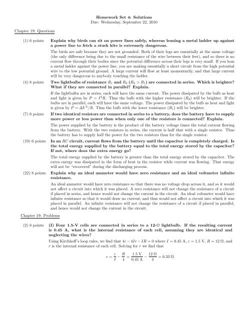
<strong>Homework</strong> Set 4: Solutions<br />
Due: Wednesday, September 22, 2010<br />
Chapter 19: Questions<br />
(1) 6 points Explain why birds can sit on power lines safely, whereas leaning a metal ladder up against<br />
a power line to fetch a stuck kite is extremely dangerous.<br />
The birds are safe because they are not grounded. Both of their legs are essentially at the same voltage<br />
(the only difference being due to the small resistance of the wire between their feet), and so there is no<br />
current flow through their bodies since the potential difference across their legs is very small. If you lean<br />
a metal ladder against the power line, you are making essentially a short circuit from the high potential<br />
wire to the low potential ground. A large current will flow at least momentarily, and that large current<br />
will be very dangerous to anybody touching the ladder.<br />
(4) 8 points Two lightbulbs of resistance R 1 and R 2 (R 2 > R 1 ) are connected in series. Which is brighter<br />
What if they are connected in parallel Explain.<br />
If the lightbulbs are in series, each will have the same current. The power dissipated by the bulb as heat<br />
and light is given by P = I 2 R. Thus the bulb with the higher resistance (R 2 ) will be brighter. If the<br />
bulbs are in parallel, each will have the same voltage. The power dissipated by the bulb as heat and light<br />
is given by P = ∆V 2 /R. Thus the bulb with the lower resistance (R 1 ) will be brighter.<br />
(7) 6 points If two identical resistors are connected in series to a battery, does the battery have to supply<br />
more power or less power than when only one of the resistors is connected Explain.<br />
The power supplied by the battery is the product of the battery voltage times the total current flowing<br />
from the battery. With the two resistors in series, the current is half that with a single resistor. Thus<br />
the battery has to supply half the power for the two resistors than for the single resistor.<br />
(19) 6 points In an RC circuit, current flows from the battery until the capacitor is completely charged. Is<br />
the total energy supplied by the battery equal to the total energy stored by the capacitor<br />
If not, where does the extra energy go<br />
The total energy supplied by the battery is greater than the total energy stored by the capacitor. The<br />
extra energy was dissipated in the form of heat in the resistor while current was flowing. That energy<br />
will not be “recovered” during the discharging process.<br />
(22) 8 points Explain why an ideal ammeter would have zero resistance and an ideal voltmeter infinite<br />
resistance.<br />
Chapter 19: Problems<br />
An ideal ammeter would have zero resistance so that there was no voltage drop across it, and so it would<br />
not affect a circuit into which it was placed. A zero resistance will not change the resistance of a circuit<br />
if placed in series, and hence would not change the current in the circuit. An ideal voltmeter would have<br />
infinite resistance so that it would draw no current, and thus would not affect a circuit into which it was<br />
placed in parallel. An infinite resistance will not change the resistance of a circuit if placed in parallel,<br />
and hence would not change the current in the circuit.<br />
(2) 8 points (I) Four 1.5-V cells are connected in series to a 12-Ω lightbulb. If the resulting current<br />
is 0.45 A, what is the internal resistance of each cell, assuming they are identical and<br />
neglecting the wires<br />
Using Kirchhoff’s loop rules, we find that 4ε−4Ir−IR = 0 where I = 0.45 A, ε = 1.5 V, R = 12 Ω, and<br />
r is the internal resistance of each cell. Solving for r we find that<br />
r = ε I − R 4 = 1.5 V<br />
0.45 A − 12 Ω = 0.33 Ω.<br />
4
(8) 8 points (I) Given only one 25-Ω and one 35-Ω resistor, list all possible values of resistance that can<br />
be obtained.<br />
The possible resistances are each resistor considered individually (25 Ω and 35 Ω), the series combination<br />
(60 Ω), and the parallel combination (15 Ω).<br />
(26) 10 points For the circuit shown in Fig. 19-46, find the potential difference between points a and b.<br />
Each resistor has R = 75 Ω and each battery is 1.5 V.<br />
Using Kirchhoff’s loop rule, we find that 2ɛ−4IR = 0 where ɛ = 1.5 V and R = 75 Ω. Solving for the<br />
current I in the circuit we find that<br />
I = ε<br />
2R .<br />
Therefore, the potential difference between points a and b is<br />
( ε<br />
)<br />
∆V ab = ε−2IR = ε−2 R = 0.<br />
2R<br />
Thus points a and b are at the same electric potential.<br />
(32) 14 points (III) (a) Determine the currents I 1 , I 2 , and I 3 in Fig. 19-50. Assume the internal resistance<br />
of each battery is r = 1.0 Ω. (b) What is the terminal voltage of the 6.0-V battery<br />
(a) Since there are three currents to determine, there must be three independent equations to determine<br />
those currents. One comes from Kirchhoff’s junction rule<br />
I 1 = I 2 +I 3 .<br />
Another equation comes from Kirchhoff’s loop rule applied to the top loop<br />
which simplifies to<br />
(12.0 V)−I 2 (1.0 Ω)−I 2 (10 Ω)−I 1 (12 Ω)+(12.0 V)−I 1 (1.0 Ω)−I 1 (8.0 Ω) = 0,<br />
24 = 21I 1 +11I 2 .<br />
The final equation comes from Kirchhoff’s loop rule applied to the bottom loop<br />
which simplifies to<br />
(12.0 V)−I 2 (1.0 Ω)−I 2 (10 Ω)+I 3 (18 Ω)+I 3 (1.0 Ω)−(6.0 V)+I 3 (15 Ω) = 0<br />
6 = 11I 2 −34I 3 .<br />
Substituting I 1 = I 2 +I 3 into the top loop equation yields<br />
24 = 32I 2 +21I 3 .<br />
Multiplying both sides of the bottom loop equation by (32/11) and subtracting it from this equation<br />
yields a result for I 3<br />
I 3 = 0.0546A = 0.055 A.<br />
With this result, we also find that<br />
I 1 = 0.77 A and I 2 = 0.71 A.<br />
Therefore, I 1 = 0.77 A, I 2 = 0.71 A and I 3 = 0.055 A.<br />
(b) The terminal voltage of the 6.0-V battery is<br />
∆V = ε−I 3 r = (6.0 V)−(0.0546 A)(1.0 Ω) = 5.9 V.
(38) 10 points (II) If 26.0 V is applied across the whole network of Fig. 19-52, calculate the voltage across<br />
each capacitor.<br />
The full voltage is across the 2.00 µF capacitor, and so ∆V 2.00 = 26.0 V. To find the voltage across the<br />
two capacitors in series, we first note that they have the same charge (conservation of charge). Therefore<br />
Therefore,<br />
and<br />
26.0 V =<br />
Q<br />
3.00×10 −6 F + Q<br />
4.00×10 −6 F<br />
∆V 3.00 = 4.46×10⁻⁵ C<br />
3.00×10 −6 F = 14.9 V<br />
∆V 4.00 = 4.46×10⁻⁵ C<br />
4.00×10 −6 = 11.1 V.<br />
F<br />
so Q = 4.46×10 −5 C.<br />
(52) (16 points) (III) Two resistors and two uncharged capacitors are arranged as shown in Fig. 19-58.<br />
Then a potential difference of 24 V is applied across the combination as shown. (a) What<br />
is the potential at point a with switch S open (Let V = 0 at the negative terminal of the<br />
source.) (b) What is the potential at point b with the switch open (c) When the switch<br />
is closed, what is the final potential of point b (d) How much charge flows through the<br />
switch S after it is closed<br />
(a) Using Kirchhoff’s loop rule we find that ∆V − IR 1 −IR 2 = 0 where ∆V = 24 V, R 1 = 8.8 Ω and<br />
R 2 = 4.4 Ω. Solving for I we find that<br />
I = ∆V 24 V<br />
= = 1.818 A.<br />
R 1 +R 2 8.8 Ω+4.4 Ω<br />
Therefore, the voltage at point a is the voltage across the 4.4 Ω resistor:<br />
V a = IR 2 = (1.818 A)(4.4 Ω) = 8.0 V.<br />
(b) Using Kirchhoff’s loop rule we find that ∆V − Q C 1<br />
− Q C 2<br />
= 0 where ∆V = 24 V, C 1 = 0.48 µF and<br />
C 2 = 0.24 µF. The charge Q on each capacitor is the same due to conservation of charge. Solving for Q<br />
we find that<br />
Q = C 1C 2 (0.48 µF)(0.24 µF)<br />
∆V = (24 V) = 3.84 µC.<br />
C 1 +C 2 0.48 µF+0.24 µF<br />
The voltage at point b is the voltage across the 0.24 µF capacitor<br />
V b = Q C 2<br />
=<br />
3.84 µC<br />
= 16 V.<br />
0.24 µF<br />
(c) The switch is now closed. After equilibrium has been reached a long time, there is no current flowing<br />
in the capacitors, and so the resistors are again in series, and the voltage of point a must be 8.0 V.<br />
(d) Part (c) implies that the voltage across C 1 is 16 V while the voltage across C 2 is 8.0 V. Therefore,<br />
the charge on each capacitor is<br />
Q 1 = C 1 ∆V 1 = (16 V)(0.48 µF) = 7.68 µC<br />
Q 2 = C 2 ∆V 2 = (8.0 V)(0.24 µF) = 1.92 µC.<br />
When the switch was open, point b had a net charge of 0, because the charge on the negative plate C 1<br />
had the same magnitude as the charge on the positive plate C 2 . With the switch closed, these charges<br />
are not equal. The net charge at point b is the sum of the charge on the negative plate of C 1 and the<br />
charge on the positive plate of C 2 : Q b = Q 2 −Q 1 = −5.76 µC. Thus, 5.76 µC has passed through the<br />
switch.