Ultrafly Focke- Wulf 190 - CML Distribution
Ultrafly Focke- Wulf 190 - CML Distribution
Ultrafly Focke- Wulf 190 - CML Distribution

Create successful ePaper yourself
Turn your PDF publications into a flip-book with our unique Google optimized e-Paper software.
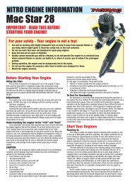
This version of the<br />
‘Butcher Bird’ offers easy<br />
flying and fine<br />
performance.<br />
Review by John Wheater<br />
<br />
<strong>Ultrafly</strong> <strong>Focke</strong>-<br />
<strong>Wulf</strong> <strong>190</strong><br />
No fewer than 40 different versions<br />
of Kurt Tank’s FW<strong>190</strong> were<br />
produced. So, describing an<br />
aircraft as an ‘FW<strong>190</strong>’ is as generic<br />
as referring to a ‘Spitfire’.<br />
The later versions had in-line engines but<br />
their use of annular radiators gives the<br />
impression that they are radials. <strong>Ultrafly</strong>’s<br />
model is one of the earlier BMW radialengined<br />
variants, an FW<strong>190</strong>A.<br />
The Kit<br />
The box is fairly substantial with the<br />
components packed individually in<br />
polythene bags separated by cardboard<br />
packing pieces to ensure they do not move<br />
during transit.<br />
The airframe is made up of six main<br />
components; the fuselage and cowling, two<br />
wing halves and the tailplane and rudder.<br />
The quality of the building looks superlative.<br />
The cutting of the parts is by laser and they<br />
have been lightened wherever possible. The<br />
Lite-ply seems to be of sound quality.<br />
The fuselage is a little unusual in that the<br />
top half from the firewall to aft of the canopy<br />
is a single, clear plastic vacuum moulding. It<br />
has been beautifully sprayed ‘body colour’,<br />
after being fitted to the fuselage. It is a good<br />
idea allowing things like cannon blisters to<br />
be easily and convincingly moulded but the<br />
downside is that the cockpit is sealed off and<br />
there is no pilot.<br />
All of the hardware components needed to<br />
complete the build are provided. The review<br />
version also included an outrunner motor<br />
and a matched ESC and suitable propeller.<br />
Motor Installation<br />
When undertaking a review I always<br />
attempt to adhere to the instruction sheet as<br />
it is there for a purpose. But with so few<br />
components, the instructions are largely<br />
superfluous. The wing is detailed first for<br />
assembly followed by the tailplane and fin/<br />
rudder but I dived in halfway through at the<br />
installation of the motor and cowling as I<br />
prefer to have those installed before I fit the<br />
empennage as without it, the fuselage is<br />
easier to manoeuvre around the building<br />
board.<br />
A cross is etched onto the front of the<br />
wooden motor mount to ensure that the<br />
motor’s radial mount is positioned correctly.<br />
One should note that it isn’t central but offset<br />
to take into account the side thrust. The<br />
motor box itself is built to incorporate three<br />
degrees of side thrust and two degrees of<br />
down thrust.<br />
Here’s a tip not shown in the instructions<br />
for fitting a radial cowl to ensure that the<br />
crankshaft end actually comes out of the<br />
cowl in the centre. Using a pair of compasses<br />
draw a circle to a slightly lesser diameter than<br />
the cowl’s front aperture on a piece of paper.<br />
Ensure that the centre is well marked. Cut<br />
out the disc slightly larger than you have<br />
12 Q&EFI October 2007<br />
QEFI OCT pFW<strong>190</strong>.indd 12 11/9/07 10:17:14
Kit Review FW<strong>190</strong><br />
drawn it and stick it accurately with tape to<br />
the cowl. Place the cowl on the model and<br />
centre the propshaft on the centre you have<br />
marked on your paper disc, then tape the<br />
cowl to the fuselage temporarily to drill the<br />
mounting screw holes.<br />
One should always file flats on the motor<br />
shaft to allow the grub screws a decent grip<br />
so I did this, then I fitted the prop adapter<br />
and came up with a problem.<br />
Now I don’t think I am lacking in<br />
intelligence, in fact I believe my IQ exceeds<br />
ten, but I struggled with the supplied<br />
spinner/prop/prop adapter combination. The<br />
spinner front is affixed with two self-tappers<br />
from behind the prop driver leaving a clean<br />
and unsullied front to the spinner. But this<br />
means that the prop/spinner and adapter has<br />
to be assembled before it is fitted to the<br />
motor shaft which means that the cowl has to<br />
be in place first. The instructions are no help<br />
at all in this respect. It is possible to do it<br />
because, after undoing its four retaining<br />
screws, the cowl can be moved back far<br />
<br />
enough to tighten the grub screws on the<br />
prop adapter but what a performance.<br />
Break a prop on the field and it would be a<br />
major operation to replace it so I substituted<br />
a 2" standard plastic yellow spinner.<br />
The supplied propeller is an APC 10" x 7"<br />
which, on a 2300 16C 3S 2P LiPoly, draws 28<br />
A at 6,500 rpm, that is 310 W. For a 31 oz<br />
model that should be quite enough.<br />
The Rest of the Fuselage<br />
The assembly was simplicity itself. The<br />
slots in the fuselage for the tailplane and fin<br />
were correctly cut and everything aligned<br />
perfectly. Whilst the instructions dictate<br />
that you should “Leave some space for the<br />
‘U’ shaped elevator connecting wire” it<br />
doesn’t mention that you should slot it in<br />
before you slot in the tailplane. You won’t<br />
get it in afterwards without surgery. I<br />
inserted the tailplane dry and fixed it with<br />
cyano once it was in place, inside and<br />
outside the joint.<br />
<br />
<br />
<br />
<br />
The fin to fuselage top joint isn’t<br />
aesthetically pleasing so after affixing it with<br />
epoxy, I filled the space with a mix of epoxy<br />
and micro-balloons and painted it ‘body<br />
colour’.<br />
The Wing<br />
The wing assembly is quite straightforward<br />
using a ply dihedral brace and the servo is<br />
fitted by gluing on a piece of pre-cut Lite-ply.<br />
There is only the one servo actuating the<br />
ailerons by torque rods. One thing I always<br />
do, after having had the covering on the wing<br />
of an ARTF come away in flight, is to tack the<br />
leading edges of the film to ensure that it is<br />
secure. The <strong>Ultrafly</strong> FW<strong>190</strong>’s wings looked<br />
OK in this department but it’s best to be sure.<br />
Hairy cyano hinges are supplied. I always<br />
peg them by drilling through and inserting<br />
pieces of cocktail stick with a blob of cyano<br />
after they are in place.<br />
The elevator and rudder horns have<br />
moulded pegs which, after securing with<br />
cyano I riveted over with a hot modelling<br />
knife rendering them less likely to pull<br />
through.<br />
The undercarriage slots in the wing were a<br />
little short for the U/C torque rods<br />
necessitating a little lengthening with the<br />
Dremel, I cut 1/4” from the tops of the doors<br />
as, a) they seemed to be extra long and b) I<br />
fly from grass.<br />
The tailwheel has a nice brass mount and<br />
fits perfectly into the pre-drilled fin.<br />
However, I found the plastic wheel retainer to<br />
be a bit of a sloppy fit and put on a blob of<br />
epoxy instead.<br />
The decals are plastic, printed on a white<br />
base so you must take care when cutting<br />
them out. The decal sheet is larger than the<br />
box so it was folded over, making the sheet<br />
slightly difficult to work with.<br />
Radio Installation<br />
I opted for three E-Sky 8 g EK2-0500 servos<br />
with dimensions of 22.8 mm x 11.5 mm x<br />
20.8 mm. They are quite fast and the torque<br />
is a respectable 18 oz/inch. I had to enlarge<br />
the length of the ply apertures slightly, but a<br />
tip here; don’t sand the ones in the fuselage<br />
as the dust finds its way into the cockpit and<br />
is impossible to remove, clinging to the clear<br />
canopy with the static. Use a knife and the<br />
October 2007 Q&EFI 13<br />
QEFI OCT pFW<strong>190</strong>.indd 13 11/9/07 10:18:25
esultant debris will fall out if you turn the<br />
fuselage upright and tap it.<br />
The pushrods for the rudder and elevators<br />
are of different length. ‘Z’ bends need to be<br />
made on them at one end and keepers are<br />
supplied for the other end. A trap for the<br />
unwary, they are not slotted as is usual so<br />
have to be fitted onto the pushrods before<br />
the right angle bend is made with pliers.<br />
The lightening holes in the servo tray serve<br />
a good purpose in that the servo wires can be<br />
tucked out of sight. It’s a neat installation<br />
and there was plenty of room for the twopart<br />
receiver from my Spektrum 2.4.<br />
Battery Installation And<br />
Balancing<br />
The C of G is shown as 40 – 45 mm on the<br />
centre section from the front wing mount,<br />
not the leading edge. It is possible to move<br />
the chosen battery backwards and forwards<br />
to obtain the balance. You should apply some<br />
sticky backed ‘Hook & Loop’ to your battery<br />
to ensure it stays where you intend it to.<br />
There is already fixed a ‘Hook & Loop’ strap<br />
for battery retention. There isn’t a battery<br />
box cover and the aperture for access is<br />
simply a cut out in the cowl. I stuck some<br />
tape over the aperture for flight just in case.<br />
Control Throws<br />
I was a little baffled by the control throw<br />
suggestions which recommend 5 mm min<br />
and 7 mm max on the elevator. I assumed it<br />
was a total of 10 mm or 14 mm so that was<br />
OK, about what I would have thought. But<br />
on to the ailerons, the suggested throw is 15<br />
mm min and 20 mm max. They couldn’t<br />
possibly mean 40 mm total could they An<br />
inch and a half I don’t think so. I set them<br />
up with 15 mm total on full throw. There is a<br />
small amount of differential built in. I<br />
adjusted the rates in the Tx to give<br />
something less than this for the initial part of<br />
the first flight at least. After the first flight I<br />
tweaked up the transmitter to give me 120%<br />
movement on the ailerons, a total of 20 mm,<br />
i.e. 12 mm up and 8 mm down. I have not<br />
<br />
<br />
<br />
seen an instruction sheet that recommends<br />
exponential rates as well, but <strong>Ultrafly</strong><br />
suggests 20+, 15+ and 10+ on elevator,<br />
aileron and rudder respectively. I usually put<br />
in a little more than this but each to his own.<br />
If you are not using the exponential<br />
properties of your transmitter, ask a<br />
seasoned flyer what they are for and how<br />
they will help you improve your flying.<br />
Flying<br />
I fly from a turf farm and I wondered how<br />
those small wheels would cope, but holding<br />
in full up elevator soon had the <strong>Wulf</strong> in the<br />
air. There was plenty of power but it soon<br />
became obvious that I needed full rates on<br />
the ailerons to put it through its paces. Even<br />
so, it was a delight to fly and with low rates<br />
anyone with a little experience on an aileron<br />
trainer would find it quite benign. Loops<br />
were quite large and it tracked as straight as<br />
an arrow. Rolls were reasonably axial but<br />
there is quite a lot of dihedral so a little work<br />
on the elevators is needed to get it around in<br />
a reasonable fashion.<br />
<br />
<br />
<br />
<br />
<br />
Whilst the breeze was quite light at ground<br />
level, it was a bit bumpy at around seventy<br />
feet so I climbed and put it into wind to<br />
check the stall. I throttled back and gently<br />
applied up elevator to a point where there<br />
was absolutely no ground speed. Blow me it<br />
was hovering! It was coming gently down as<br />
if it was an autogyro and may even have<br />
landed if I had let it, but I applied full<br />
throttle and was away again. With the timer<br />
beeping at five minutes I lined up for a<br />
landing which was a piece of cake until the<br />
last inch when the turf got the better of those<br />
small wheels and it nosed over. No damage<br />
except for a crack in one of the wheel doors.<br />
Because of the damage to the wheel door I<br />
removed the undercarriage for the second<br />
flight. I also racked up full aileron deflection<br />
to the 120% already noted. My son did the<br />
honours with the hand launch. Standing<br />
quite still holding one hand under the cowl<br />
and the other behind the wing it really didn’t<br />
need much of a shove to get it airborne.<br />
14 Q&EFI October 2007<br />
QEFI OCT pFW<strong>190</strong>.indd 14 11/9/07 10:18:53
Kit Review FW<strong>190</strong><br />
<br />
<br />
<br />
<br />
<br />
<br />
<br />
<br />
<br />
<br />
<br />
<br />
<br />
There was no difference flying with or<br />
without the wheels but it does look better<br />
without them doesn’t it<br />
The vertical performance isn’t quite what I<br />
had expected given the current draw on the<br />
motor but it would go up to a reasonable<br />
height before running out of steam. The<br />
ailerons were now much more responsive<br />
and I could throw it about a bit more. I<br />
thoroughly enjoyed it.<br />
Epilogue<br />
Once I had the review out of the way I<br />
couldn’t resist fitting a pilot. To cut out the<br />
cockpit floor from inside would mean taking<br />
the pushrods out of a bulkhead and, frankly,<br />
interfering with the structural integrity so I<br />
opted for cutting the canopy. It is an easy job<br />
as the canopy opening lines are well<br />
moulded. The plastic is quite thick however,<br />
so I used a new blade and simply took my<br />
time.<br />
Once I had Hanna Reisch installed, I glued<br />
two pieces of ABS to the insides of the<br />
cockpit with Canopy Glue then when it was<br />
dry used the same stuff to secure the cockpit.<br />
<br />
<br />
I also wafted the airbrush over the fuselage<br />
and flying surfaces to take some of the gloss<br />
away. Not exact scale but it adds a little<br />
character.<br />
Summary<br />
The <strong>Ultrafly</strong> FW<strong>190</strong> isn’t really a park flyer,<br />
it needs too much sky, but it isn’t a powerful<br />
lead sled either. As it is designed it is an<br />
entirely capable machine and one that is<br />
forgiving enough for a novice. The next time<br />
out I shall use a larger battery as it will cope<br />
with the weight easily, in fact I would say it<br />
will be a positive advantage and I will, of<br />
course, have quite a bit more duration.<br />
Would I recommend it Certainly.<br />
Q&EFI<br />
<br />
October 2007 Q&EFI 15<br />
QEFI OCT pFW<strong>190</strong>.indd 15 11/9/07 10:19:49
Model Information<br />
Name: <strong>Ultrafly</strong> FW-<strong>190</strong> (UF-<strong>190</strong>-F12A28:<br />
kit with motor and ESC)<br />
Price: £139.99 with motor, BEC and prop<br />
as tested. £84.99 Airframe only<br />
Manufacturer: <strong>Ultrafly</strong> (China)<br />
Distributor: <strong>CML</strong> <strong>Distribution</strong> Ltd, Saxon<br />
House, Saxon Business Park, Hanbury<br />
Road, Bromsgrove, Worcestershire B60<br />
4AD<br />
Website: www.cmldistribution.co.uk<br />
Model Type: Electric Scale ARTF<br />
Construction: Balsa and Lite-ply with film<br />
covering<br />
Model Specifications:<br />
Wingspan: 46.5"/1180 mm<br />
Fuselage: 36.5"/925 mm<br />
Wing Area: 336 sq. in/21.7 dm 2<br />
Flying Weight: 890 g (31 oz) with 2300 3S<br />
2P LiPoly<br />
R/C Functions<br />
1. Aileron<br />
2. Elevator<br />
3. Throttle (ESC)<br />
4. Rudder<br />
Likes<br />
Quality of the construction<br />
Complete inventory<br />
Ease of construction<br />
Vice-less flying qualities<br />
Dislikes<br />
The spinner<br />
Fixed cockpit canopy and no pilot<br />
Some ambiguity in the instructions<br />
16 Q&EFI October 2007<br />
QEFI OCT pFW<strong>190</strong>.indd 16 11/9/07 10:20:27