1756HP-GPS-IRIG-IN User Manual - Hiprom
1756HP-GPS-IRIG-IN User Manual - Hiprom
1756HP-GPS-IRIG-IN User Manual - Hiprom

Create successful ePaper yourself
Turn your PDF publications into a flip-book with our unique Google optimized e-Paper software.
<strong>1756HP</strong>-<strong>IRIG</strong>-<strong>IN</strong><br />
USER MANUAL<br />
Rev 2.7 – March 2009
<strong>1756HP</strong>-<strong>IRIG</strong>-<strong>IN</strong> <strong>User</strong> <strong>Manual</strong> Rev 2.7<br />
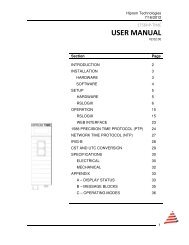
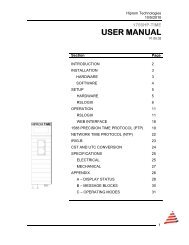
Table of Contents<br />
Chapter 1 Introduction.......................................................................................................3<br />
Chapter 2 Module Accessories.........................................................................................4<br />
Chapter 3 Module Operation.............................................................................................5<br />
Chapter 4 Installing the Module ........................................................................................7<br />
Chapter 5 Configuring the Module....................................................................................8<br />
Chapter 6 I/O Address Map ............................................................................................12<br />
Chapter 7 Module Specific Commands ..........................................................................14<br />
Chapter 8 Module Status ................................................................................................18<br />
Appendix A PLC Ladder Example.....................................................................................20<br />
Appendix B Recommended PLC Data Types ...................................................................21<br />
Appendix C Specifications .................................................................................................24<br />
Appendix D Time standards ..............................................................................................25<br />
Appendix E <strong>IRIG</strong> Standard ................................................................................................27<br />
Appendix F Glossary .........................................................................................................29<br />
.<br />
Page 2 of 29
<strong>1756HP</strong>-<strong>IRIG</strong>-<strong>IN</strong> <strong>User</strong> <strong>Manual</strong> Rev 2.7<br />
CHAPTER 1<br />
<strong>IN</strong>TRODUCTION<br />
The <strong>1756HP</strong>-<strong>IRIG</strong>-<strong>IN</strong> module provides accurate time information and services for the<br />
Allen-Bradley ControlLogix PLC system.<br />
A <strong>1756HP</strong>-<strong>IRIG</strong>-<strong>IN</strong> makes use of an <strong>IRIG</strong>-B signal supplied from a <strong>1756HP</strong>-<strong>GPS</strong>-<strong>IRIG</strong>-<br />
OUT source. The module supports <strong>IRIG</strong>-B-122.<br />
This document describes the functionality, installation, configuration and use of the<br />
module.<br />
.<br />
Page 3 of 29
<strong>1756HP</strong>-<strong>IRIG</strong>-<strong>IN</strong> <strong>User</strong> <strong>Manual</strong> Rev 2.7<br />
CHAPTER 2<br />
MODULE ACCESSORIES<br />
Each <strong>1756HP</strong>-<strong>IRIG</strong>-<strong>IN</strong> package includes the following components:<br />
• <strong>1756HP</strong>-<strong>IRIG</strong>-<strong>IN</strong> module<br />
• <strong>1756HP</strong>-<strong>IRIG</strong>-<strong>IN</strong> user manual<br />
• <strong>IRIG</strong>-Breakout and 500mm patch lead<br />
.<br />
Page 4 of 29
<strong>1756HP</strong>-<strong>IRIG</strong>-<strong>IN</strong> <strong>User</strong> <strong>Manual</strong> Rev 2.7<br />
CHAPTER 3<br />
MODULE OPERATION<br />
The <strong>1756HP</strong>-<strong>IRIG</strong>-<strong>IN</strong> module is designed to operate within the Allen-Bradley ControlLogix<br />
PLC system. All power required for the module’s operation is derived from the 1756<br />
backplane.<br />
Alphanumeric Display<br />
Status LEDs<br />
External <strong>IRIG</strong> Interface Port<br />
SMA Antenna Port (not used)<br />
Figure 3.1 : <strong>1756HP</strong>-<strong>IRIG</strong>-<strong>IN</strong> Layout<br />
The <strong>1756HP</strong>-<strong>IRIG</strong>-<strong>IN</strong> derives the <strong>IRIG</strong> signal via the external RJ45 connector. The RJ45<br />
connector interfaces to an external device, the <strong>IRIG</strong>-BREAKOUT. As soon as the module<br />
receives a valid and reliable <strong>IRIG</strong> signal, the module will indicate that the time is valid.<br />
.<br />
Page 5 of 29
<strong>1756HP</strong>-<strong>IRIG</strong>-<strong>IN</strong> <strong>User</strong> <strong>Manual</strong> Rev 2.7<br />
The current status of the module is conveyed to the user by means of the 3 bi-color Status<br />
LED’s and the alphanumeric LED display.<br />
The following information is available to the user directly across the backplane by means<br />
of a scheduled connection:<br />
• Date and Time in Gregorian Format (year, month, day, hour, minute etc.)<br />
• Universal Coordinate Time (UTC)<br />
The module requires regular updates of the ControlLogix Controller’s CST (Coordinate<br />
System Time) value to enable accurate CST conversion and wall-clock offset functions.<br />
The <strong>1756HP</strong>-<strong>IRIG</strong>-<strong>IN</strong> module supports two unconnected time conversion services, namely:<br />
• CST UTC and Gregorian<br />
• UTC Gregorian<br />
This allows the user by means of a custom message service to convert between different<br />
time formats. The conversion is valid only for time data that is less than 1 hour old.<br />
.<br />
Page 6 of 29
<strong>1756HP</strong>-<strong>IRIG</strong>-<strong>IN</strong> <strong>User</strong> <strong>Manual</strong> Rev 2.7<br />
CHAPTER 4<br />
<strong>IN</strong>STALL<strong>IN</strong>G THE MODULE<br />
The module is equipped with a RIUP (Removal and Insertion Under Power) circuitry<br />
enabling the module to be installed or removed from the chassis while power is applied.<br />
Attach the patch lead of the <strong>IRIG</strong>-BREAKOUT to module’s RJ45 connector.<br />
Once a valid and reliable <strong>IRIG</strong> signal has been received for three consecutive seconds the<br />
module will indicate that the time is valid.<br />
.<br />
Page 7 of 29
<strong>1756HP</strong>-<strong>IRIG</strong>-<strong>IN</strong> <strong>User</strong> <strong>Manual</strong> Rev 2.7<br />
CHAPTER 5<br />
CONFIGUR<strong>IN</strong>G THE MODULE<br />
A direct connection between the controller and the <strong>1756HP</strong>-<strong>IRIG</strong>-<strong>IN</strong> module is required to<br />
transfer I/O data to and from the module. In addition the module supports various<br />
unconnected messages that can be used to retrieve particular information.<br />
5.1. Establishing the Direct Connection<br />
This section describes the procedures necessary to configure the <strong>1756HP</strong>-<strong>IRIG</strong>-<strong>IN</strong> module<br />
within the ControlLogix system. Each <strong>1756HP</strong>-<strong>IRIG</strong>-<strong>IN</strong> module must be owned by a single<br />
ControlLogix controller.<br />
The 1756 Generic Module is used in RSLogix5000 to configure the module. The<br />
configuration of the module is detailed in the table below.<br />
Data Format<br />
CommFormat<br />
Data – D<strong>IN</strong>T<br />
Connection parameters<br />
Description Instance Size<br />
Input 1 29<br />
Output 2 5<br />
Configuration 4 2<br />
RPI<br />
Min 1.0 msec Max 750.0 msec<br />
Table 5.1 : <strong>1756HP</strong>-<strong>IRIG</strong>-<strong>IN</strong> connection parameters.<br />
The steps required to add a new <strong>1756HP</strong>-<strong>IRIG</strong>-<strong>IN</strong> module are detailed below.<br />
Figure 5.1 : Right-click on I/O Configuration and select New Module<br />
.<br />
Page 8 of 29
<strong>1756HP</strong>-<strong>IRIG</strong>-<strong>IN</strong> <strong>User</strong> <strong>Manual</strong> Rev 2.7<br />
Figure 5.2 : Select Generic 1756 Module ( 1756-MODULE )<br />
Figure 5.3 : Configure module’s parameters<br />
.<br />
Page 9 of 29
<strong>1756HP</strong>-<strong>IRIG</strong>-<strong>IN</strong> <strong>User</strong> <strong>Manual</strong> Rev 2.7<br />
Figure 5.4 : Configure module’s RPI (Requested Packet Interval)<br />
The first word of the Configuration Image configures the module as a <strong>1756HP</strong>-<strong>GPS</strong>-<strong>IRIG</strong>-<br />
<strong>IN</strong>. Set the first word of the image to 0x02. If the user is using RSLogix 5000 v16 the UTC<br />
time base is different from previous versions of RSLogix. To ensure that ControlLogix<br />
PLC’s running different versions can be time synced using the <strong>1756HP</strong>-<strong>GPS</strong>-<strong>IRIG</strong>-<strong>IN</strong><br />
module the user must select if v16 is used or not. The last bit (least significant bit) of the<br />
second byte of the configuration image configures the module to use or not use v16 UTC<br />
time. By setting the bit, the module will use v16 UTC time. The highest bit (most significant<br />
bit) of the second byte of the configuration image configures the module to be the CST<br />
master. By setting this bit, the module will attempt to become the CST master. If a CST<br />
master is present, it will not become the CST master and indicate that a duplicate master<br />
was detected.<br />
Configuration Image<br />
BYTE VALUE<br />
0 0x02<br />
1 0x<br />
Byte 1 = X000 000Y (binary) where ‘X’ will make the module a CST master if set to 1 and<br />
‘Y’ will make the module use v16 UTC time if set to 1.<br />
Once a modules configuration data has been downloaded to the controller, it will attempt<br />
to establish a connection with the module. A connection will fail if there is inappropriate<br />
configuration data.<br />
.<br />
Page 10 of 29
<strong>1756HP</strong>-<strong>IRIG</strong>-<strong>IN</strong> <strong>User</strong> <strong>Manual</strong> Rev 2.7<br />
5.2. Coordinate System Time Master<br />
It is important that at least one controller or <strong>1756HP</strong>-<strong>GPS</strong>-<strong>IRIG</strong>-<strong>IN</strong> module in the<br />
ControlLogix rack be configured as the Coordinate System Time master. This can be<br />
configured in RSLogix5000 by right-clicking on the Controller and selecting Properties.<br />
Ensure that the checkbox as indicated below is checked to make the controller the CST<br />
master; otherwise the procedure in section 5.1 above may be followed to make the<br />
<strong>1756HP</strong>-<strong>GPS</strong>-<strong>IRIG</strong>-<strong>IN</strong> module the CST master.<br />
Figure 5.5 : Configure CST Master<br />
.<br />
Page 11 of 29
<strong>1756HP</strong>-<strong>IRIG</strong>-<strong>IN</strong> <strong>User</strong> <strong>Manual</strong> Rev 2.7<br />
CHAPTER 6<br />
I/O ADDRESS MAP<br />
The input and output image of the <strong>1756HP</strong>-<strong>IRIG</strong>-<strong>IN</strong> module is defined in the following<br />
sections. Appendix A and B provide example code and recommended structures that can<br />
be used to extract and view the data.<br />
6.1. Input Image<br />
Figure 6.1 : Connected Input Image<br />
6.2. Input Image Description<br />
Field/Value Description Location Type<br />
Module OK<br />
Module Status<br />
0 = Module has faulted<br />
1 = Module is operating properly<br />
Local:s:I.Data[0].16<br />
BIT<br />
Lock<br />
Lock<br />
0 = Not receiving sufficient <strong>IRIG</strong> signal<br />
1 = Sufficient <strong>IRIG</strong> signal being received<br />
Local:s:I.Data[0].17<br />
BIT<br />
CST Ok<br />
Valid CST<br />
1 = Module is receiving updates CST<br />
0 = Module has not received updated CST for 1sec or<br />
more<br />
Local:s:I.Data[0].18<br />
BIT<br />
.<br />
Page 12 of 29
<strong>1756HP</strong>-<strong>IRIG</strong>-<strong>IN</strong> <strong>User</strong> <strong>Manual</strong> Rev 2.7<br />
Time Valid<br />
Date / Time Valid<br />
0 = Date Time Not Valid<br />
1 = Date Time synchronized<br />
Local:s:I.Data[0].19<br />
BIT<br />
PPS<br />
Pulse per Second<br />
This bit transitions from 0 to 1 precisely every second.<br />
The pulse duty cycle is approximately 50%.<br />
Local:s:I.Data[0].20<br />
BIT<br />
Reserved Local:s:I.Data[0].21..26 BIT<br />
<strong>IRIG</strong>_<strong>IN</strong><br />
<strong>IRIG</strong><strong>IN</strong> Configuration bit<br />
Indicates that the module has been configured as an<br />
<strong>IRIG</strong><strong>IN</strong> module<br />
Local:s:I.Data[0].27 BIT<br />
Dup Master<br />
A duplicate CST master has been detected<br />
0 = No duplicate CST master detected<br />
1 = A duplicate CST master is detected<br />
Local:s:I.Data[0].28<br />
BIT<br />
CST Master<br />
This module is the local rack CST master<br />
0 = This module is not the CST master<br />
1 = This module is the CST master<br />
Local:s:I.Data[0].29<br />
BIT<br />
Reserved Local:s:I.Data[0].30..31 BIT<br />
Reserved Local:s:I.Data[1] D<strong>IN</strong>T<br />
Calendar Year<br />
Year Current Local Calendar Year<br />
Local:s:I.Data[2] D<strong>IN</strong>T<br />
Calendar Month<br />
Month<br />
Current Local Calendar Month ( 1 - 12 )<br />
Local:s:I.Data[3] D<strong>IN</strong>T<br />
Calendar Day of Month<br />
Day<br />
Current Local Calendar Day ( 1 - 31 )<br />
Local:s:I.Data[4] D<strong>IN</strong>T<br />
Real Time Hours<br />
Hours Current Local time Hours ( 0 - 23 )<br />
Local:s:I.Data[5] D<strong>IN</strong>T<br />
Real Time Minutes<br />
Minutes Current Local time Minutes ( 0 - 59 )<br />
Local:s:I.Data[6] D<strong>IN</strong>T<br />
Real Time Seconds<br />
Seconds<br />
Current real time Seconds ( 0 - 59 )<br />
Local:s:I.Data[7] D<strong>IN</strong>T<br />
Real Time Microseconds<br />
Microseconds Current real time Microseconds ( 0 – 999 999 )<br />
Local:s:I.Data[8] D<strong>IN</strong>T<br />
Local:s:I.Data[9]<br />
UTC Current Universal Time Constant (UTC)<br />
To<br />
64BIT<br />
Local:s:I.Data[10]<br />
CST Current CLX Coordinate System Time (CST)<br />
Local:s:I.Data[11]<br />
To<br />
64BIT<br />
Local:s:I.Data[12]<br />
CST Offset<br />
Current CLX Coordinate System Time (CST) Offset<br />
Current Time = CST + CST Offset<br />
Local:s:I.Data[13]<br />
To<br />
Local:s:I.Data[14]<br />
64BIT<br />
6.3. Output Image<br />
The current year is entered in word 3.<br />
.<br />
Page 13 of 29
<strong>1756HP</strong>-<strong>IRIG</strong>-<strong>IN</strong> <strong>User</strong> <strong>Manual</strong> Rev 2.7<br />
CHAPTER 7<br />
MODULE SPECIFIC COMMANDS<br />
The <strong>1756HP</strong>-<strong>IRIG</strong>-<strong>IN</strong> module offers specific commands that enable the system to perform<br />
time base conversions. These are accomplished using unconnected messaging via the<br />
MSG ladder instruction. This enables communication to the module without a direct<br />
connection.<br />
Appendix A and B provide example code and recommended data structures that can be<br />
used to store the information.<br />
7.1. Converting Time Bases<br />
The <strong>1756HP</strong>-<strong>IRIG</strong>-<strong>IN</strong> stores a rolling log of the CST/UTC pairs for the last 1 hour.<br />
Timestamps in a system can either be CST or UTC values. The <strong>1756HP</strong>-<strong>IRIG</strong>-<strong>IN</strong> module<br />
provides functionality for converting between values that are within the last hour.<br />
7.2. Converting CST to UTC and Gregorian<br />
By supplying the full 64 bit CST value, the module will return the corresponding full<br />
Gregorian date and UTC value. Configuration of this message is illustrated below.<br />
.<br />
Page 14 of 29
<strong>1756HP</strong>-<strong>IRIG</strong>-<strong>IN</strong> <strong>User</strong> <strong>Manual</strong> Rev 2.7<br />
Figure 7.2: Configuring the MSG CST->UTC conversion request instruction.<br />
Refer to Appendix A for code examples.<br />
Field<br />
Value<br />
Message Type<br />
CIP Generic<br />
Service Type<br />
Custom<br />
Service Code<br />
0x32<br />
Class<br />
0x70<br />
Instance<br />
0x01<br />
Attribute<br />
0x01<br />
Source Length 0<br />
Destination Element<br />
Destination tag for reply data<br />
Table 7.3: CST->UTC conversion request configuration.<br />
The structure of the request is as follows:<br />
Field Bytes Type Description<br />
CST 8 D<strong>IN</strong>T[2] CST value<br />
Table 7.4 : CST->UTC conversion request data.<br />
A successful conversion will result in the following response:<br />
Field Bytes Type Description<br />
Year 2 D<strong>IN</strong>T Gregorian year<br />
Month 2 D<strong>IN</strong>T Gregorian month<br />
Day 2 D<strong>IN</strong>T Gregorian day<br />
Hour 2 D<strong>IN</strong>T Gregorian hour<br />
Min 2 D<strong>IN</strong>T Gregorian min<br />
Sec 2 D<strong>IN</strong>T Gregorian sec<br />
µSec 2 D<strong>IN</strong>T Gregorian µSec<br />
UTC 8 D<strong>IN</strong>T[2] Corresponding UTC value<br />
CST 8 D<strong>IN</strong>T[2] Given CST value<br />
Table 7.5: CST->UTC conversion successful response data.<br />
An unsuccessful response (code 0x03) will be sent back should the CST not fall within the<br />
previous logged hour.<br />
.<br />
Page 15 of 29
<strong>1756HP</strong>-<strong>IRIG</strong>-<strong>IN</strong> <strong>User</strong> <strong>Manual</strong> Rev 2.7<br />
7.3. Converting UTC to Gregorian Time<br />
By supplying the full 64 bit UTC value, the module will return the corresponding full<br />
Gregorian date. Configuration of this message is illustrated below.<br />
Figure 7.3: Configuring the MSG UTC->Gregorian conversion request instruction.<br />
The message instruction should be configured as follows :<br />
Field<br />
Value<br />
Message Type<br />
CIP Generic<br />
Service Type<br />
Custom<br />
Service Code<br />
0x33<br />
Class<br />
0x70<br />
Instance<br />
0x01<br />
Attribute<br />
0x01<br />
Source Element<br />
Tag containing requested UTC value<br />
Source Length 8<br />
Destination Element<br />
Destination tag for reply data<br />
Table 7.6 : UTC->Gregorian conversion request configuration.<br />
.<br />
Page 16 of 29
<strong>1756HP</strong>-<strong>IRIG</strong>-<strong>IN</strong> <strong>User</strong> <strong>Manual</strong> Rev 2.7<br />
The structure of the request is as follows :<br />
Field Bytes Type Description<br />
UTC 8 D<strong>IN</strong>T[2] UTC value<br />
Table 7.7 : UTC->Gregorian conversion response data.<br />
A successful conversion will result in the following response :<br />
Field Bytes Type Description<br />
Year 2 D<strong>IN</strong>T Gregorian year<br />
Month 2 D<strong>IN</strong>T Gregorian month<br />
Day 2 D<strong>IN</strong>T Gregorian day<br />
Hour 2 D<strong>IN</strong>T Gregorian hour<br />
Min 2 D<strong>IN</strong>T Gregorian min<br />
Sec 2 D<strong>IN</strong>T Gregorian sec<br />
µSec 2 D<strong>IN</strong>T Gregorian µSec<br />
UTC 8 D<strong>IN</strong>T[2] Corresponding UTC value<br />
Table 7.8 : UTC->Gregorian conversion successful response data.<br />
An unsuccessful response will be sent back should the UTC not fall within the previous<br />
recorded hour.<br />
.<br />
Page 17 of 29
<strong>1756HP</strong>-<strong>IRIG</strong>-<strong>IN</strong> <strong>User</strong> <strong>Manual</strong> Rev 2.7<br />
CHAPTER 8<br />
MODULE STATUS<br />
The following sections describe the various status of the module and how they may be<br />
determined via the 3 bi-color (Green / Red ) LEDs and the message on the display.<br />
8.1. Status LEDs<br />
LED DESCRIPTION STATUS MEAN<strong>IN</strong>G<br />
Solid Red Major Hardware Fault<br />
OK Module Status Flashing Red Major Fault<br />
Flashing Green Minor Fault<br />
Green<br />
Module operating correctly<br />
Solid Red No <strong>IRIG</strong> Signal<br />
LOC <strong>IRIG</strong>-B Lock Status Green Receiving valid <strong>IRIG</strong> signal<br />
Solid Red No PPS available<br />
PPS Pulse Per Second Flashing Red Premature PPS (before valid <strong>IRIG</strong><br />
signal)<br />
Flashing Green Normal Synchronized to <strong>IRIG</strong> signal<br />
Table 8.1 : LED status information of the module.<br />
.<br />
Page 18 of 29
<strong>1756HP</strong>-<strong>IRIG</strong>-<strong>IN</strong> <strong>User</strong> <strong>Manual</strong> Rev 2.7<br />
8.2. Status Display<br />
Init<br />
Initialization of Module<br />
The module is initialized only on power-up.<br />
Frn<br />
Firmware Revision<br />
The firmware revision number is displayed on power-up.<br />
Tm<br />
Time unknown<br />
Indicates that the module is not receiving valid <strong>IRIG</strong> signal and can<br />
not synchronize time.<br />
TmOk Time Ok<br />
Indicates that the module is valid <strong>IRIG</strong> signal and that the time is<br />
synchronized.<br />
C->U<br />
Time Conversion CST UTC<br />
Module is performing a time conversion<br />
U->G<br />
Time Conversion UTC Gregorian<br />
Module is performing a time conversion<br />
.<br />
Page 19 of 29
<strong>1756HP</strong>-<strong>IRIG</strong>-<strong>IN</strong> <strong>User</strong> <strong>Manual</strong> Rev 2.7<br />
APPENDIX A<br />
PLC LADDER EXAMPLE<br />
Configure module and copy data to UDT<br />
Convert CST value to UTC and Gregorian format<br />
.<br />
Page 20 of 29
<strong>1756HP</strong>-<strong>IRIG</strong>-<strong>IN</strong> <strong>User</strong> <strong>Manual</strong> Rev 2.7<br />
Convert UTC value to Gregorian format<br />
Synchronize ControlLogix System Time<br />
Copy UTC / CST pairs to SOE Input module ( located in slot 4 )<br />
APPENDIX B<br />
RECOMMENDED PLC DATA TYPES<br />
.<br />
Page 21 of 29
<strong>1756HP</strong>-<strong>IRIG</strong>-<strong>IN</strong> <strong>User</strong> <strong>Manual</strong> Rev 2.7<br />
This Appendix provides a detailed description of recommended data structures that can be<br />
used in conjunction with the provided example ladder code. The following structures (and<br />
example code) can be downloaded from the <strong>Hiprom</strong> website. ( www.hiprom.com )<br />
B.1 Input Image Structures<br />
• Data of the <strong>1756HP</strong>-<strong>IRIG</strong>-<strong>IN</strong> can be presented clearly by copying the input image to<br />
the <strong>IRIG</strong>BImage user-defined data type (UDT) structure.<br />
<strong>IRIG</strong>BImage<br />
Name Data Type Style<br />
Reserved <strong>IN</strong>T Decimal<br />
ModuleOk BOOL Decimal<br />
<strong>IRIG</strong>BOk BOOL Decimal<br />
CSTOk BOOL Decimal<br />
TimeOk BOOL Decimal<br />
PPS BOOL Decimal<br />
Reserved BOOL Decimal<br />
Reserved BOOL Decimal<br />
Reserved BOOL Decimal<br />
Reserved BOOL Decimal<br />
Reserved BOOL Decimal<br />
Reserved BOOL Decimal<br />
<strong>IRIG</strong>-<strong>IN</strong>Config BOOL Decimal<br />
Dup Master BOOL Decimal<br />
CST Master BOOL Decimal<br />
Reserved BOOL Decimal<br />
Reserved BOOL Decimal<br />
Reserved D<strong>IN</strong>T Decimal<br />
Year D<strong>IN</strong>T Decimal<br />
Month D<strong>IN</strong>T Decimal<br />
Day D<strong>IN</strong>T Decimal<br />
Hour D<strong>IN</strong>T Decimal<br />
Minute D<strong>IN</strong>T Decimal<br />
Second D<strong>IN</strong>T Decimal<br />
Microsecond D<strong>IN</strong>T Decimal<br />
UTC D<strong>IN</strong>T[2] Decimal<br />
CST D<strong>IN</strong>T[2] Decimal<br />
CSTOffset D<strong>IN</strong>T[2] Decimal<br />
Table B.1 : <strong>IRIG</strong>BImage UDT<br />
B.2 Unconnected message Structures<br />
.<br />
Page 22 of 29
<strong>1756HP</strong>-<strong>IRIG</strong>-<strong>IN</strong> <strong>User</strong> <strong>Manual</strong> Rev 2.7<br />
The following structure can be used for the CST to Gregorian conversion via the<br />
unconnected message. The structure holds both the data sent and received.<br />
<strong>IRIG</strong>BConvCST<br />
Name Data Type Style<br />
CSTRequest D<strong>IN</strong>T[2] Decimal<br />
Year D<strong>IN</strong>T Decimal<br />
Month D<strong>IN</strong>T Decimal<br />
Day D<strong>IN</strong>T Decimal<br />
Hour D<strong>IN</strong>T Decimal<br />
Minute D<strong>IN</strong>T Decimal<br />
Second D<strong>IN</strong>T Decimal<br />
Microsecond D<strong>IN</strong>T Decimal<br />
UTC D<strong>IN</strong>T[2] Decimal<br />
CST D<strong>IN</strong>T[2] Decimal<br />
Table B.6 : <strong>IRIG</strong>BConvCST UDT<br />
The following structure can be used for the UTC to Gregorian conversion via the<br />
unconnected message. The structure holds both the data sent and received.<br />
<strong>IRIG</strong>BConvUTC<br />
Name Data Type Style<br />
UTCRequest D<strong>IN</strong>T[2] Decimal<br />
Year D<strong>IN</strong>T Decimal<br />
Month D<strong>IN</strong>T Decimal<br />
Day D<strong>IN</strong>T Decimal<br />
Hour D<strong>IN</strong>T Decimal<br />
Minute D<strong>IN</strong>T Decimal<br />
Second D<strong>IN</strong>T Decimal<br />
Microsecond D<strong>IN</strong>T Decimal<br />
UTC D<strong>IN</strong>T[2] Decimal<br />
Table B.4 : <strong>IRIG</strong>BConvUTC UDT<br />
.<br />
Page 23 of 29
<strong>1756HP</strong>-<strong>IRIG</strong>-<strong>IN</strong> <strong>User</strong> <strong>Manual</strong> Rev 2.7<br />
APPENDIX C<br />
SPECIFICATIONS<br />
Parameter<br />
Specification<br />
General<br />
Module Location Any Slot<br />
<strong>IRIG</strong><br />
Format<br />
B122, 1kHz, Amplitude Modulated Sine Wave<br />
Electrical<br />
Backplane Current 515mA @ 5.1V<br />
3mA @ 24V<br />
Schedules Connection Parameters<br />
RPI<br />
1.0ms to 750ms<br />
.<br />
Page 24 of 29
<strong>1756HP</strong>-<strong>IRIG</strong>-<strong>IN</strong> <strong>User</strong> <strong>Manual</strong> Rev 2.7<br />
APPENDIX D<br />
TIME STANDARDS<br />
There are many different time standards used in the world today. This chapter describes<br />
the different formats and standards used in the <strong>1756HP</strong>-<strong>IRIG</strong>-<strong>IN</strong> module and how the<br />
relate to one another.<br />
D.1 Universal Coordinate Time (UTC)<br />
Universal Coordinate Time (UTC) is the world standard maintained by an ensemble of<br />
atomic clocks operated by government organizations around the world. UTC time replaced<br />
GMT (Greenwich Mean Time) as the world standard, in 1986. <strong>GPS</strong> time is steered relative<br />
to Universal Coordinated Time (UTC). <strong>GPS</strong> does not recognize leap seconds resulting in<br />
the aforementioned <strong>GPS</strong> UTC Offset. The <strong>1756HP</strong>-<strong>IRIG</strong>-<strong>IN</strong> module reports UTC as a 64<br />
bit unsigned long integer representing the number of elapsed microseconds since 1<br />
January 1972. This UTC value is thus independent of the Configured Time Zone.<br />
D.2 Coordinate System Time (CST)<br />
The CST (Coordinated System Time) is a 64 bit count of the number of microsecond ticks<br />
from some arbitrary instance. This value is generated by the CST master and supplied to<br />
all other modules in the rack. Only one of the modules, (usually the CPU,) in the<br />
ControlLogix rack can be configured to be the CST Master at any given time.<br />
D.3 Wall Clock Time (WCT) and CST Offset<br />
The wall clock object located in the ControlLogix CPU maintains the conversion of the CST<br />
value to a value that is relative to a system defined point in time. This allows the user to<br />
set the Wall Clock to coincide with local or any other time standard. WCT is derived from<br />
the CST by adding an offset known as the CST Offset.<br />
WCT = CST + (CST Offset)<br />
The <strong>1756HP</strong>-<strong>IRIG</strong>-<strong>IN</strong> module calculates the required CST Offset in order to set the WCT<br />
to UTC time or local time depending on the configured Time Zone.<br />
.<br />
Page 25 of 29
<strong>1756HP</strong>-<strong>IRIG</strong>-<strong>IN</strong> <strong>User</strong> <strong>Manual</strong> Rev 2.7<br />
TimeZone<br />
<strong>GPS</strong> Time<br />
<strong>GPS</strong> UTC Offset<br />
+<br />
UTC<br />
-<br />
+<br />
+<br />
+<br />
Local Time<br />
SSV<br />
WCT<br />
-<br />
CST Offset<br />
SSV<br />
WCT Offset<br />
+<br />
+<br />
CST<br />
GSV<br />
CST<br />
<strong>1756HP</strong>-<strong>GPS</strong><br />
ControlLogix CPU<br />
Figure F.1 : Time Standard Relationship<br />
.<br />
Page 26 of 29
<strong>1756HP</strong>-<strong>IRIG</strong>-<strong>IN</strong> <strong>User</strong> <strong>Manual</strong> Rev 2.7<br />
APPENDIX E<br />
<strong>IRIG</strong> STANDARD<br />
<strong>IRIG</strong> was developed by the Tele Communication Working Group (TCWG) of the Inter<br />
Range Instrumentation group (<strong>IRIG</strong>) in October 1965. The latest <strong>IRIG</strong> standard is<br />
published in <strong>IRIG</strong> Standard 200-98.<br />
<strong>IRIG</strong> is a standard for transmitting time from one system to another for time<br />
synchronization purposes. An <strong>IRIG</strong> master transmits an <strong>IRIG</strong> signal to multiply <strong>IRIG</strong> slaves<br />
on the network. The <strong>IRIG</strong> signals consist of two words which together are exactly one<br />
second long. The first word is the time of the year in binary coded decimal (BCD) with<br />
notation in seconds (7 Bits), minutes (7 Bits), hours (6 Bits), and days (10 Bits). The<br />
second word is called the Straight Binary Seconds (SBS) and is a binary counter of the<br />
number of seconds of the day, which resets at midnight (i.e 0 to 86399 seconds). The<br />
format of a <strong>IRIG</strong> frame is detailed below:<br />
where<br />
SS:MM:HH:DDD <br />
is the on-time sync marker (Two reference bits as illustrated below)<br />
SS is the second of the minute [00 to 59 (60 during leap seconds)]<br />
MM is the minute of the hour (00 to 59)<br />
HH is the hour of day in 24 format (00 to 23)<br />
DDD is the day of year (001 to 366)<br />
is a block of 27 binary control characters<br />
(SBS) is a 17 b second of day in binary<br />
Each <strong>IRIG</strong> consists of 10 sections. Each section consists of 10 bits of 1mSec duration.<br />
Each bit can have three values: 1, 0, and position identifier (Po). A 1 is set for 5mSec, 0<br />
for 2mSec and a position identifier is set for 8mSec as illustrated below.<br />
FIGURE<br />
A position identifier Po occurs between decimal digits in each section for visual separation.<br />
An <strong>IRIG</strong> signal can either be transmitted as an amplitude-modulated or DC-level signal.<br />
Below is an illustration of both signal types. The amplitude-modulated signal is modulated<br />
with a 1kHz sine wave. Logic 1, 0, and two reference bits (at the start of the frame) are<br />
indicated below in the <strong>IRIG</strong> frame.<br />
.<br />
Page 27 of 29
<strong>1756HP</strong>-<strong>IRIG</strong>-<strong>IN</strong> <strong>User</strong> <strong>Manual</strong> Rev 2.7<br />
.<br />
Page 28 of 29
<strong>1756HP</strong>-<strong>IRIG</strong>-<strong>IN</strong> <strong>User</strong> <strong>Manual</strong> Rev 2.7<br />
APPENDIX F<br />
GLOSSARY<br />
Communications format<br />
Format that defines the type of information transferred between an I/O module and its<br />
owner controller. This format also defines the tags created for each /O module<br />
Coordinated System Time (CST)<br />
Timer value which is kept synchronized for all modules within a single ControlBus chassis.<br />
The CST is a 64 bit number with µs resolution.<br />
Download<br />
The process of transferring the contents of a project on the workstation into the controller<br />
<strong>GPS</strong> (Global Positioning System)<br />
A constellation of 24 radio navigation (not communication) satellites which transmit<br />
signals used (by <strong>GPS</strong> receivers) to determine precise location (position, velocity, and time)<br />
solutions. <strong>GPS</strong> signals are available world-wide, 24 hours a day, in all weather conditions.<br />
This system also includes 5 monitor ground stations, 1 master control ground station, and<br />
3 upload ground stations.<br />
Owner controller<br />
The controller that creates and stores the primary configuration and communication<br />
connection to a module<br />
Producer/consumer<br />
Intelligent data exchange system devices in which the <strong>GPS</strong> module produces data without<br />
having been polled first.<br />
Removal and insertion under power (RIUP)<br />
ControlLogix feature that allows a user to install or remove a module or RTB while power<br />
is applied.<br />
Requested packet interval (RPI)<br />
A configurable parameter which defines when the module will multicast data<br />
Service<br />
A system feature that is performed on user demand<br />
Signal to noise ratio<br />
A measure of the relative power levels of a communication signal and noise on a data line.<br />
SNR is expressed in decibels (dB).<br />
Tag<br />
A named area of the controller’s memory where data is stored like a variable<br />
(………………./// end of document )<br />
.<br />
Page 29 of 29