Swirl Diffuser TSA 20 - Halton
Swirl Diffuser TSA 20 - Halton
Swirl Diffuser TSA 20 - Halton

Create successful ePaper yourself
Turn your PDF publications into a flip-book with our unique Google optimized e-Paper software.
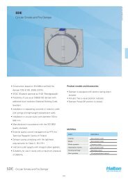
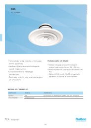
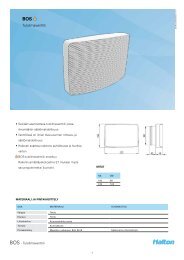
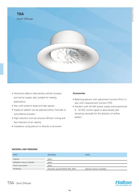
<strong>TSA</strong><br />
<strong>Swirl</strong> <strong>Diffuser</strong><br />
<strong>20</strong>/<strong>TSA</strong>/3500/1107/EN<br />
• Horizontal radial or alternatively vertical compact<br />
swirl jet air supply, also suitable for heating<br />
applications<br />
• Also well suited to large and high spaces<br />
• Supply air pattern can be adjusted either manually or<br />
controlled by actuator<br />
• High induction swirl jet ensures efficient mixing and<br />
fast reduction of air velocity<br />
• Installation using plenum or directly to ductwork<br />
Accessories<br />
• Balancing plenum with adjustment function (PLC) or<br />
also with measurement function (TRI)<br />
• Actuator (with 24 VAC power supply and proportional<br />
0…10 VDC control signal or alternatively selfactuating<br />
wax-bulb) for the direction of airflow<br />
pattern<br />
MATERIAL AND FINISHING<br />
PART MATERIAL NOTE<br />
Casing<br />
Steel<br />
Deflector ring or cylinder<br />
Steel<br />
Front vane panel<br />
Steel<br />
Finishing Polyester painted White RAL 9010 Special colours available<br />
<strong>TSA</strong> - <strong>Swirl</strong> <strong>Diffuser</strong><br />
186
QUICK SELECTION<br />
Pa 1<strong>20</strong>0 1440 1800 2160 2640 3240 4<strong>20</strong>0 5400 7<strong>20</strong>0 9000 10800 13<strong>20</strong>0 16800<br />
qv l/s 100 1<strong>20</strong> 150 180 2<strong>20</strong> 270 350 450 600 750 900 1100 1400<br />
m 3 /h 360 432 540 648 792 972 1260 16<strong>20</strong> 2160 2700 3240 3960 5040<br />
<strong>20</strong>/<strong>TSA</strong>/3500/1107/EN<br />
<strong>TSA</strong>-250(R) LpA 23 29 37 45 54<br />
DPst 19 27 42 60 90<br />
DPtot 21 30 47 68 102<br />
Ld 2,2 2,4 2,6 3,0 3,4<br />
Lmin 2,6 3,4 4,8 6,2 8,0<br />
L0.2 2,3 2,8 3,4 4,2 5,2<br />
<strong>TSA</strong>-315(R) LpA 23 28 35 43 55<br />
DPst 14 <strong>20</strong> 30 46 77<br />
DPtot 16 23 35 53 89<br />
Ld 2,4 2,6 3,2 3,4 4,2<br />
Lmin 3,4 4,4 6,0 7,8 10,6<br />
L0.2 2,8 3,4 4,2 5,2 6,8<br />
<strong>TSA</strong>-400(R) LpA 25 34 43 55<br />
DPst 16 27 45 79<br />
DPtot 19 32 52 93<br />
Ld 3,0 3,6 4,2 5,0<br />
Lmin 5,6 8,0 10,8 15,0<br />
L0.2 5,0 6,4 8,2 11,0<br />
<strong>TSA</strong>-500(R) LpA 26 36 45 52<br />
DPst 17 30 47 68<br />
DPtot <strong>20</strong> 36 56 80<br />
Ld 3,2 4,0 4,8 5,4<br />
Lmin 8,2 11,6 15,0 18,4<br />
L0.2 6,0 8,2 10,2 12,2<br />
<strong>TSA</strong>-600(R) LpA 22 29 35 42 52<br />
DPst 11 17 25 37 60<br />
DPtot 13 21 30 45 73<br />
Ld 3,0 3,6 4,2 5,0 5,8<br />
Lmin 8,8 11,4 14,2 17,8 23,2<br />
L0.2 6,4 8,0 9,6 11,8 15,0<br />
LpA values presented with room attenuation 4 dB (red 10m 2 -<br />
sab). When using room attenuation 8 dB (red 25m 2 - sab):<br />
LpA - 4dB.<br />
Pa<br />
LpA<br />
DPst<br />
Supply air cooling capacity, W<br />
A-weighted sound pressure level, reduced by total<br />
equivalent absorption surface of 10m 2 , dB(A) red<br />
10m 2 - sab<br />
Static pressure drop, Pa<br />
DPtot<br />
Ld<br />
Lmin<br />
Total pressure drop, Pa<br />
Distance from the supply unit, at which air jet<br />
detaches from ceiling, m<br />
Minimum distance between central lines of two<br />
supply units, m (V3 = 0,25m/s at 1.8m height)<br />
L0.2 Isotermal throw length, m when residual velocity of<br />
supply air jet 0,2 m/s<br />
Room temperature (Tr) = 24 °C<br />
Supply air temperature (Ta) = 14 °C<br />
Room height<br />
= 2,8 m<br />
<strong>TSA</strong> - <strong>Swirl</strong> <strong>Diffuser</strong><br />
187
QUICK SELECTION<br />
Pa 1440 1800 2160 2640 31<strong>20</strong> 3600 4<strong>20</strong>0 4800 5400 6000 7<strong>20</strong>0 9000 10800 13<strong>20</strong>0 15600<br />
qv l/s 1<strong>20</strong> 150 180 2<strong>20</strong> 260 300 350 400 450 500 600 750 900 1100 1300<br />
m 3 /h 432 540 648 792 936 1080 1260 1440 16<strong>20</strong> 1800 2160 2700 3240 3960 4680<br />
<strong>TSA</strong>-250(C) LpA 22 30 37 46 53<br />
DPst 22 35 50 75 104<br />
DPtot 26 40 58 87 121<br />
L0.2 2,8 3,6 4,4 5,6 6,8<br />
<strong>20</strong>/<strong>TSA</strong>/3500/1107/EN<br />
<strong>TSA</strong>-315(C) LpA 17 22 28 34 39 44 49 53<br />
DPst 12 17 26 36 48 65 85 108<br />
DPtot 14 <strong>20</strong> 30 43 57 77 101 128<br />
L0.2 2,4 3,0 4,0 4,8 5,6 6,8 8,0 9,0<br />
<strong>TSA</strong>-400(C) LpA 19 23 28 33 37 42 49<br />
DPst 12 16 22 28 36 44 64<br />
DPtot 15 19 26 34 44 54 78<br />
L0.2 3,0 3,6 4,2 5,0 5,8 6,6 8,2<br />
<strong>TSA</strong>-500(C) LpA 21 24 28 33 41 48<br />
DPst 10 13 16 23 35 51<br />
DPtot 12 16 <strong>20</strong> 28 44 63<br />
L0.2 2,8 3,2 3,8 4,6 6,2 7,6<br />
<strong>TSA</strong>-600(C) LpA 22 29 34 41 47<br />
DPst 9 14 <strong>20</strong> 30 42<br />
DPtot 11 17 25 37 52<br />
L0.2 2,6 3,4 4,2 5,2 6,4<br />
LpA values presented with room attenuation 4 dB (red 10m 2 -<br />
sab). When using room attenuation 8 dB (red 25m 2 - sab):<br />
LpA - 4dB.<br />
Pa<br />
LpA<br />
DPst<br />
Supply air cooling capacity, W<br />
A-weighted sound pressure level, reduced by total<br />
equivalent absorption surface of 10m 2 , dB(A) red<br />
10m 2 - sab<br />
Static pressure drop, Pa<br />
DPtot<br />
Ld<br />
Total pressure drop, Pa<br />
Distance from the supply unit, at which air jet<br />
detaches from ceiling, m<br />
L0,2 Isotermal throw length, m when residual velocity of<br />
supply air jet 0,2 m/s<br />
Room temperature (Tr) = 24 °C<br />
Supply air temperature (Ta) = 14 °C<br />
Room height<br />
= 2,8 m<br />
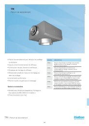
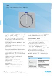
DIMENSIONS<br />
10<br />
NS ØD ØW H<br />
250 249 382 221<br />
315 314 475 233<br />
400 399 593 246<br />
Ø W<br />
Ø D<br />
500 499 735 264<br />
630 629 917 286<br />
176<br />
H<br />
<strong>TSA</strong> with electrical actuator<br />
Ø D<br />
NS ØD ØW H H3<br />
250 249 382 221 430<br />
315 314 475 233 459<br />
H3<br />
400 399 593 246 486<br />
500 499 735 264 499<br />
630 629 917 286 524<br />
Ø W<br />
176<br />
10<br />
H<br />
<strong>TSA</strong> with wax-bulb actuator<br />
Ø D<br />
NS ØD ØW H H2<br />
250 249 382 221 273<br />
315 314 475 233 302<br />
H2<br />
176<br />
H<br />
400 399 593 246 329<br />
500 499 735 264 342<br />
10<br />
630 629 917 286 367<br />
Ø W<br />
<strong>TSA</strong> - <strong>Swirl</strong> <strong>Diffuser</strong><br />
188
<strong>20</strong>/<strong>TSA</strong>/3500/1107/EN<br />
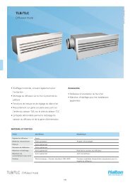
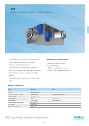
Compact jet<br />
Radial Jet<br />
Function<br />
• The <strong>TSA</strong> is a high induction swirl diffuser with an<br />
adjustable flow pattern. The horizontal radial swirl jet<br />
is used mainly in cooling applications that use cool<br />
supply air or for ventilation with isothermal supply air.<br />
• The vertical compact swirl jet with warm supply air<br />
is used in heating applications.<br />
• Adjustment of the supply air pattern is effected by<br />
moving the internal adjustment element (cylinder).<br />
• It is also possible to change from cooling mode to<br />
heating mode by adjusting the flow pattern using an<br />
electric or wax bulb actuator.<br />
• The recommended maximum temperature<br />
differences between room and supply air<br />
temperatures are +15 °C for heating and -15 °C for<br />
cooling applications.<br />
Product models<br />
<strong>TSA</strong> with electric actuator<br />
• Siemens GDB161.2E/HA actuator with 24 VAC power<br />
supply and proportional 0…10 VDC control signal<br />
<strong>TSA</strong> with wax-bulb actuator<br />
• <strong>TSA</strong> can be equipped with a wax-bulb actuator, which<br />
work without any power supply. The cylinder position<br />
changes according to the temperature of supply air.<br />
• The temperature range of the wax-bulb actuator is<br />
about <strong>20</strong> °C to 27 °C.<br />
• The time taken to change from radial to compact jet<br />
(or the other way around) is 10 - <strong>20</strong> minutes.<br />
• When warm air is supplied the piston of the wax<br />
bulb actuator keeps moving until the <strong>TSA</strong> supply air<br />
pattern is vertical. When cold air is supplied, the <strong>TSA</strong><br />
supply air pattern is changed back to horizontal by<br />
means of a spring.<br />
<strong>TSA</strong> - <strong>Swirl</strong> <strong>Diffuser</strong><br />
189
Installation<br />
The diffuser is connected either directly to the duct<br />
by screwing or riveting or alternatively to TRI or PLC<br />
balancing plenum.<br />
The front vane panel can be reattached<br />
Remove the screws through the front vane panel<br />
(sizes 250 and 315) or between the cylinder and<br />
casing (sizes 400, 500 and 630), turn and hold the<br />
front vane panel to remove.<br />
Installation with plenum<br />
<strong>TSA</strong> with TRI plenum<br />
<strong>TSA</strong> ØD1 TRI H1 ØW1<br />
250 <strong>20</strong>0 TRI-<strong>20</strong>0-250 390-535 310<br />
315 250 TRI-250-315 465-610 400<br />
400 315 TRI-315-400 525-670 500<br />
<strong>TSA</strong> with PLC plenum<br />
<strong>20</strong>/<strong>TSA</strong>/3500/1107/EN<br />
Take care during installation to ensure that the cylinder<br />
can move freely and that the actuator has adequate<br />
installation space. There should be at least 50 mm<br />
clearance space above the top of the device when the<br />
cylinder is in the lowest position. The connection and<br />
fixing rivets or screws may not be located more than<br />
50 mm below the upper edge of the diffuser.<br />
<strong>TSA</strong> ØD1 PLC H1 ØW1<br />
500 500 PLC 500 810-950 6<strong>20</strong><br />
630 630 PLC 630 850-990 785<br />
It is recommended that the distance between the PLC plenum<br />
and <strong>TSA</strong> sizes 500 and 630 is at least 1xD to ensure proper<br />
diffuser operation.<br />
A minimum safety distance upstream of the diffuser<br />
of 3xD is recommended.<br />
Ensure that the actuator has adequate installation<br />
space when installed in TRI plenum. It is<br />
recommended to install the collar outwards.<br />
H1<br />
H<br />
The technical performance for the combination of<br />
supply air diffuser and TRI plenum is presented<br />
separately for the two different installations. See HIT<br />
Design software.<br />
0<br />
10<br />
Ø W1<br />
<strong>TSA</strong> - <strong>Swirl</strong> <strong>Diffuser</strong><br />
190
<strong>20</strong>/<strong>TSA</strong>/3500/1107/EN<br />
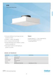
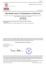
Adjustment<br />
CODE DESCRIPTION<br />
1 Control knob<br />
2 Casing<br />
3 Front vane panel<br />
4 Cylinder<br />
Throw pattern adjustment<br />
The supply air jet is adjusted by changing the position<br />
of the cylinder.<br />
When you turn the knob clockwise the throw pattern<br />
is changes from radial to compact.<br />
Pass the tubes and control spindle through the front<br />
vane panel.<br />
Measure the differential pressure using a manometer.<br />
The flow rate is calculated using the formula below.<br />
q<br />
v<br />
= k *<br />
p<br />
m<br />
Adjust the airflow rate by rotating the control spindle<br />
until the desired setting is achieved. Replace the tubes<br />
and spindle in the plenum.<br />
Airflow adjustment<br />
It is not possible to adjust the airflow in <strong>TSA</strong> itself.<br />
In order to enable airflow adjustment and<br />
measurement of airflow rate it is recommended<br />
that you connect the diffuser <strong>TSA</strong> 250, 315 and<br />
400 to the TRI balancing plenum. The supply flow<br />
rate is determined by using the measurement and<br />
adjustment module MSM.<br />
<strong>TSA</strong> - <strong>Swirl</strong> <strong>Diffuser</strong><br />
191
Pressure drop, throw pattern and sound data<br />
Supply, radial jet, ceiling installation flush to the<br />
ceiling<br />
<strong>TSA</strong>-250, <strong>TSA</strong>-315, <strong>TSA</strong>-400<br />
<strong>TSA</strong>-500, <strong>TSA</strong>-630<br />
<strong>TSA</strong>-500(R)<br />
<strong>TSA</strong>-630(R)<br />
<strong>20</strong>/<strong>TSA</strong>/3500/1107/EN<br />
Selection example :<br />
Requirements : qv = 350 l/s Selection : <strong>TSA</strong>-400<br />
LpA < 35 dB(A)<br />
LpA = 34 dB(A)<br />
L0,2 < 8,0 L0,2 = 8,0<br />
Horizontal jet<br />
DPtot = 32 Pa<br />
Note :<br />
For exposed installation horizontal the throw pattern can be<br />
reduced by approximately 30 %, of the value given in the diagram.<br />
With isothermal air, the throw pattern can be calculated for other<br />
terminal velocity by using correction factor :<br />
L0.3 = L0.2 x 0.67<br />
L0.4 = L0.2 x 0.5<br />
With non-isothermal air, the throw pattern changes due to air<br />
density. Please refer to next page or to the <strong>Halton</strong> HIT. CD-rom<br />
calculation program.<br />
SOUND LEVEL DATA<br />
Radial Jet qv DPst DPtot F (Hz) LpA NR NC<br />
(l/s) (m 3 /h) (Pa) (Pa) 125 250 500 1000 <strong>20</strong>00 4000 8000 [dB(A)]<br />
<strong>TSA</strong>-250(R) 108 389 21 24 29 26 26 26 19 15 15 25 22 <strong>20</strong><br />
124 446 28 32 32 29 29 31 26 <strong>20</strong> 18 30 27 25<br />
141 508 37 42 36 32 32 36 33 25 21 35 32 31<br />
160 576 47 54 39 35 35 41 39 30 23 40 38 36<br />
<strong>TSA</strong>-315(R) 163 587 17 19 29 27 28 25 17 13 14 25 21 19<br />
189 680 22 26 32 30 31 31 24 17 17 30 27 25<br />
217 781 30 34 36 33 34 36 31 22 21 35 32 31<br />
248 893 39 45 39 35 36 41 38 26 24 40 37 36<br />
<strong>TSA</strong>-400(R) 271 976 16 19 28 26 29 24 15 14 15 25 21 19<br />
316 1138 22 26 33 30 32 31 22 19 18 30 27 25<br />
364 1310 29 34 37 33 36 37 28 24 22 35 33 31<br />
414 1490 38 44 41 36 39 42 34 28 25 40 38 37<br />
<strong>TSA</strong>-500(R) 433 1559 16 18 29 26 28 25 17 13 14 25 21 19<br />
505 1818 21 25 33 29 31 31 24 19 18 30 27 25<br />
583 <strong>20</strong>99 28 33 37 32 34 36 31 24 21 35 32 31<br />
664 2390 37 44 40 35 37 41 38 29 24 40 37 36<br />
<strong>TSA</strong>-630(R) 660 2376 13 16 29 26 28 25 16 12 14 25 21 19<br />
776 2794 19 22 34 30 31 31 24 18 18 30 27 25<br />
896 3226 25 30 37 33 34 36 31 23 21 35 32 31<br />
1029 3704 33 39 41 36 37 41 37 28 24 40 37 36<br />
LpA values presented with room attenuation 4 dB (red 10m 2 - sab). When using room attenuation 8 dB (red 25m 2 - sab): LpA - 4dB.<br />
NR/NC noise criteria<br />
<strong>TSA</strong> - <strong>Swirl</strong> <strong>Diffuser</strong><br />
192
Pressure drop, throw pattern and sound data<br />
Supply, compact jet, ceiling installation<br />
<strong>20</strong>/<strong>TSA</strong>/3500/1107/EN<br />
<strong>TSA</strong>-250, <strong>TSA</strong>-315, <strong>TSA</strong>-400<br />
<strong>TSA</strong>-500, <strong>TSA</strong>-630<br />
Selection example :<br />
Requirements : qv = 350 l/s Selection : <strong>TSA</strong>-400<br />
LpA < 30 dB(A)<br />
LpA = 28 dB(A)<br />
L0,2 < 16,0 L0,2 = 15,0<br />
DPtot = 26 Pa<br />
Note :<br />
With non-isothermal air, the throw pattern changes due to air<br />
density. Please refer to next page or to the <strong>Halton</strong> HIT software.<br />
SOUND LEVEL DATA<br />
Compact Jet qv DPst DPtot F (Hz) LpA NR NC<br />
(l/s) (m 3 /h) (Pa) (Pa) 125 250 500 1000 <strong>20</strong>00 4000 8000 [dB(A)]<br />
<strong>TSA</strong>-250(C) 130 468 26 30 29 26 26 23 22 18 17 25 21 19<br />
149 536 34 40 32 29 29 29 28 22 18 30 28 25<br />
170 612 45 52 35 32 33 34 34 26 <strong>20</strong> 35 34 31<br />
192 691 57 66 37 35 36 39 40 30 22 40 39 37<br />
<strong>TSA</strong>-315(C) 199 716 21 25 30 27 27 23 21 16 14 25 21 18<br />
232 835 29 34 31 31 32 29 27 19 15 30 27 24<br />
270 972 39 46 33 34 36 34 33 22 16 35 33 30<br />
311 11<strong>20</strong> 51 61 35 37 40 39 39 25 17 40 38 36<br />
<strong>TSA</strong>-400(C) 319 1148 18 22 29 26 29 22 <strong>20</strong> 17 17 25 <strong>20</strong> 19<br />
370 1332 24 30 32 30 32 29 26 21 <strong>20</strong> 30 25 23<br />
425 1530 32 39 34 33 35 35 32 25 22 35 31 30<br />
481 1732 41 50 37 36 38 41 37 29 25 40 37 36<br />
<strong>TSA</strong>-500(C) 458 1649 13 16 30 26 28 23 <strong>20</strong> 16 16 25 <strong>20</strong> 18<br />
539 1940 18 23 33 29 31 30 26 21 19 30 26 24<br />
628 2261 25 31 35 32 35 36 31 25 22 35 32 30<br />
726 2614 33 41 38 35 38 41 37 29 25 40 37 36<br />
<strong>TSA</strong>-630(C) 663 2387 11 14 30 26 28 23 <strong>20</strong> 15 16 25 <strong>20</strong> 18<br />
783 2819 15 19 33 29 32 30 26 <strong>20</strong> 19 30 26 24<br />
918 3305 21 26 36 32 35 36 31 25 22 35 32 30<br />
1065 3834 28 35 38 36 38 41 37 29 25 40 37 36<br />
LpA values presented with room attenuation 4 dB (red 10m 2 - sab). When using room attenuation 8 dB (red 25m 2 - sab): LpA - 4dB.<br />
NR/NC noise criteria<br />
<strong>TSA</strong> - <strong>Swirl</strong> <strong>Diffuser</strong><br />
193
Servicing<br />
Remove the front vane panel and clean the diffuser by<br />
wiping it with a damp cloth, instead of immersing it in<br />
water.<br />
Option with balancing plenum<br />
Remove the measurement and adjustment module<br />
by pulling gently the shaft; (not the control spindle or<br />
measurement tubes!).<br />
Wipe the parts with a damp cloth, instead of<br />
immersing them in water.<br />
Remount the measurement and adjustment module<br />
by pushing the shaft until the module meets the<br />
stopper.<br />
Suggested specifications<br />
Product code<br />
<strong>TSA</strong>-D<br />
D = Connection size<br />
250, 315, 400, 500, 630<br />
Specifics and accessories<br />
CO = Colour<br />
W White<br />
X Special colour<br />
MO = Actuator type<br />
NA No actuator<br />
M2 24 VAC actuator, 0...10 VDC control<br />
signal<br />
M3 Wax-bulb actuator<br />
<strong>20</strong>/<strong>TSA</strong>/3500/1107/EN<br />
The diffuser shall consist of a frame with fixed internal<br />
profiled vane rings and a movable deflector ring or<br />
cylinder for throw pattern selection.<br />
The front vane panel, the movable cylinder and the<br />
frame shall be made of powder painted steel, with a<br />
white (RAL 9010) as standard colour.<br />
The airflow pattern shall be adjustable automatically<br />
using an electrical or wax-bulb actuator, (in applications<br />
where both heating and cooling are required.)<br />
Code example<br />
<strong>TSA</strong>-250, CO=W,MO=NA<br />
Sub products<br />
PLC Plenum (Ceiling diffusers)<br />
TRI Plenum (<strong>Diffuser</strong>s)<br />
<strong>TSA</strong> - <strong>Swirl</strong> <strong>Diffuser</strong><br />
194