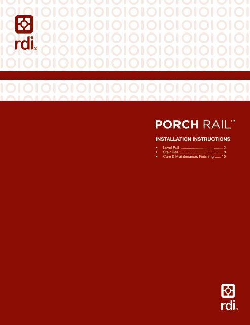
Porch Rail⢠Instruction PDF - Railing Dynamics
Porch Rail⢠Instruction PDF - Railing Dynamics
Porch Rail⢠Instruction PDF - Railing Dynamics

Create successful ePaper yourself
Turn your PDF publications into a flip-book with our unique Google optimized e-Paper software.
INSTALLATION INSTRUCTIONS<br />
• Level Rail ......................................... 2<br />
• Stair Rail .......................................... 8<br />
• Care & Maintenance, Finishing ...... 15
COMPONENT LIST<br />
LEVEL RAIL KIT<br />
<strong>Porch</strong> Rail was designed to meet the most stringent building codes. An evaluation report<br />
is available through your <strong>Porch</strong> Rail Distributor or through RDI Customer Service.<br />
COMPONENTS:<br />
Depending on the level kit and kit length you purchased your component list will vary.<br />
Use this as a guide to identify the individual components.<br />
A<br />
I<br />
B<br />
C<br />
J<br />
K<br />
L<br />
D<br />
E<br />
F<br />
H<br />
G<br />
Standard Rail Kit Wood Cover Rail Kit<br />
A.) Wood Top Cover X Sold Separately<br />
B.) Top Cover 1 X<br />
C.) Top Beam 1 X<br />
D.) Bottom Beam 1 2<br />
E.) Beam Cover 2 2<br />
F.) Baluster - Quantities Vary by Length-Round Iron & Glass Balusters Sold Separately<br />
G.) Bottom Rail Support 1 1<br />
H.) Level Mounting Bracket 4 4<br />
I.) Screw (#12 x 5") 1 1<br />
J.) Screw (#10 x 2") 8 8<br />
K.) Screw (#8 x 1") 8 8<br />
L.) Foam-Baluster Option Kits Only 2 2<br />
2<br />
Warning:<br />
Always wear<br />
safety goggles.
STANDARD LEVEL RAIL KITS<br />
1.<br />
2.<br />
3.<br />
Prepare all posts and mounting surfaces<br />
before installation.<br />
NOTE: Check with your local building<br />
code office for design load requirements<br />
for guard rails and bottom space requirements.<br />
All supporting structures should<br />
be built in accordance with applicable<br />
building codes.<br />
Establish the level placement of the<br />
lower rail so there is no more than a<br />
4" space from the bottom of the rail to<br />
the standing surface. Mark the post or<br />
mounting surface at this dimension to<br />
determine the bottom rail height. (See<br />
Fig. 1)<br />
Tip:<br />
Standard <strong>Porch</strong> Rail measures 36" in<br />
height with a 2" space below the bottom<br />
rail (See NOTE in Step 1).<br />
Measure the finished opening space<br />
between surfaces where the railing is to<br />
be installed. Transfer this measurement<br />
to the bottom beam (D) and subtract<br />
1/2" to allow for the mounting brackets<br />
(Fig. 2).<br />
Tip 1:<br />
If all of your mounting surfaces are<br />
plumb, transfer your measurements from<br />
the bottom beam to the top beam (C).<br />
Cut the beams to the measurement<br />
(Fig. 5, 6).<br />
Continued on next page. >><br />
(Fig. 2)<br />
(Fig. 3)<br />
(Fig. 4)<br />
(Fig. 1)<br />
3
4.<br />
>> Continued from previous page.<br />
Tip :<br />
If using a power saw, a carbide tip blade<br />
of at least 60 teeth is recommended.<br />
Place one of the beam covers (E) across<br />
the opening where the railing is to be<br />
installed (Fig. 7). Measure from the<br />
mounting surface to the first baluster<br />
hole on each end (Fig. 8), and adjust<br />
until these dimensions are equal. Trace<br />
the post edge onto the beam cover (E) at<br />
each end (Fig. 9).<br />
Tip:<br />
If all of mounting surfaces are plumb,<br />
transfer your measurements and baluster<br />
layout from the bottom beam cover (E) to<br />
the top beam cover (E) (Fig. 10).<br />
NOTE: A minimum of 1" from the edge<br />
of the first baluster hole to the end of the<br />
routed beam cover (E) is necessary.<br />
(Fig. 7)<br />
(Fig. 8)<br />
(Fig. 10)<br />
(Fig. 5)<br />
(Fig. 6)<br />
(Fig. 9)<br />
(Fig. 11)<br />
4
5.<br />
6.<br />
Insert mounting brackets (H) in each end<br />
of bottom beam (Fig. 12); ensure proper<br />
alignment (Fig. 13). Place the bottom<br />
beam on the marks determined in<br />
Step 2.<br />
Secure the brackets to the post using<br />
mounting screws (J) (Fig. 14). Secure the<br />
brackets to the beam using mounting<br />
screws (K).<br />
Tip:<br />
You can cut wood blocks to support the<br />
bottom beam at the proper height during<br />
installation (Fig. 15).<br />
Cut the bottom rail support (G) to the<br />
bottom space determined in Step 2 and<br />
place it under the bottom beam at the<br />
center point (Fig. 16 and 17).<br />
Pre-drill using a 1/4" dill bit for the<br />
bottom rail support screw (I) (Fig. 18).<br />
Secure the bottom rail support to the<br />
standing surface with screw provided (I).<br />
(Fig. 12)<br />
(Fig. 15)<br />
(Fig. 18)<br />
Ensure the four tabs on bracket<br />
nest on beam as depicted. (Fig. 13)<br />
(Fig. 16)<br />
(Fig. 14)<br />
(Fig. 17)<br />
5
7.<br />
8.<br />
9.<br />
Snap the bottom beam cover (E) over<br />
the bottom beam (D) (Fig. 20, 21).<br />
If installing glass or iron balusters, insert<br />
foam strip (L) into baluster channel prior<br />
to snapping on beam cover (E).<br />
Insert a baluster (F) in each hole of the<br />
bottom beam cover (E) (Fig. 22).<br />
Starting at one end of the rail section,<br />
slide the top beam cover (E) (routed flat<br />
side facing down) on top of the balusters<br />
(Fig. 23).<br />
Insert each baluster into the corresponding<br />
rout in the top beam cover (E). Let<br />
top beam cover (E) slide down on balusters,<br />
this will be used after top beam<br />
(C) and top cover (B) installations are<br />
complete (See Step 11).<br />
++++++++++++++++++++++++++++++<br />
IF INSTALLING THE WOOD TOP<br />
COVER (A) SKIP TO PAGE 14 OF THIS<br />
INSTALLATION GUIDE AND THEN<br />
RETURN TO COMPLETE STEP 12.<br />
++++++++++++++++++++++++++++++<br />
If your top beam (C) was not previously<br />
cut (Step 3), measure your finished<br />
opening, deduct 1/2”, and cut.<br />
Insert mounting brackets (H) in each end<br />
of top beam (C) (Fig. 24); ensure proper<br />
alignment (Fig. 25).<br />
(Fig. 22)<br />
(Fig. 24)<br />
(Fig. 20)<br />
Ensure the four tabs on bracket<br />
nest on beam as depicted.<br />
(Fig. 23)<br />
(Fig. 21)<br />
(Fig. 25)<br />
6
10.<br />
11.<br />
12.<br />
Place the top beam (C), as oriented in<br />
Fig. 25, between the posts and on top of<br />
the balusters (Fig. 26).<br />
Secure the brackets to the post using<br />
mounting screws (J) (Fig. 27). Secure the<br />
brackets to the beam using mounting<br />
screws (K) (Fig. 28).<br />
Measure for length (Fig. 29) and cut the<br />
top cover (B) to fit (Fig. 30).<br />
Snap the top cover (B) onto the top<br />
beam (C) by rolling the cover to one side,<br />
engaging the locking strip. Then, roll<br />
the top cover (B) to the other side while<br />
applying downward pressure. Work from<br />
one end of the rail to the other until the<br />
full length of the cover locks into place<br />
(Fig. 31).<br />
Slide the top beam cover (E) up onto the<br />
underside of the top beam (C) and snap<br />
into place (Fig. 32, 33).<br />
(Fig. 26)<br />
(Fig. 29)<br />
(Fig. 27)<br />
(Fig. 32)<br />
(Fig. 30)<br />
(Fig. 28)<br />
(Fig. 31)<br />
(Fig. 33)<br />
7
COMPONENT LIST<br />
STAIR RAIL<br />
<strong>Porch</strong> Rail was designed to meet the most stringent building codes. An evaluation report<br />
is available through your <strong>Porch</strong> Rail Distributor or through RDI Customer Service.<br />
COMPONENTS:<br />
Depending on the stair kit and kit length you purchased your component list will vary.<br />
Use this as a guide to identify the individual components.<br />
A<br />
I<br />
B<br />
C<br />
J<br />
K<br />
D<br />
E<br />
F<br />
H<br />
L<br />
G<br />
Standard Rail Kit Wood Cover Rail Kit<br />
A.) Wood Top Cover X Sold Separately<br />
B.) Top Cover 1 X<br />
C.) Top Beam 1 X<br />
D.) Bottom Beam 1 2<br />
E.) Beam Cover 2 2<br />
F.) Baluster - Quantities Vary by Length-Round Iron & Glass Balusters Sold Separately<br />
G.) Bottom Rail Support 1 1<br />
H.) Stair Mounting Bracket 4 4<br />
I.) Screw (#12 x 5") 1 1<br />
J.) Screw (#10 x 2") 8 8<br />
K.) Screw (#8 x 1") 8 8<br />
L.) Foam-Baluster Option Kits Only 2 2<br />
8<br />
Warning:<br />
Always wear<br />
safety goggles.
STANDARD STAIR KITS<br />
1.<br />
2.<br />
Prepare all posts and mounting surfaces<br />
before installation.<br />
NOTE: Check with your local building<br />
code office for design load requirements<br />
for guard rails and bottom space requirements.<br />
All supporting structures should<br />
be built in accordance with applicable<br />
building codes.<br />
Temporarily secure a plank on the nose<br />
of the stairs along side of the posts onto<br />
which you are installing the stair rail (Fig.<br />
1). The thickness of the plank will determine<br />
the space between the stairs and<br />
the bottom rail.<br />
With the white powder coated surface of<br />
the bottom beam facing down, place the<br />
bottom beam (D - Oriented as shown in<br />
the Component List) on the plank (Fig.<br />
2). Trace the angle of the posts onto the<br />
bottom beam (Fig. 3).<br />
Cut the bottom beam 1/2" shorter on<br />
one end, on the angle found in Fig. 3, to<br />
allow for mounting brackets (Fig. 4, 5).<br />
NOTE: Depending on the angle of your<br />
stair, code may require you to mount<br />
the bottom beam to the tread noses (no<br />
plank). Check with your local building office<br />
for applicable regulations.<br />
Tip:<br />
If both posts are plumb you can speed<br />
your installation by placing the top beam<br />
(C) on top of the bottom beam with the<br />
baluster channels facing each other, and<br />
mark both beams at once. Then cut both<br />
beams.<br />
(Fig. 1)<br />
(Fig. 3)<br />
(Fig. 4)<br />
(Fig. 2)<br />
(Fig. 5)<br />
9
3.<br />
4.<br />
Place a beam cover (E) on the temporary<br />
plank (Fig. 6).<br />
NOTE: Routed holes in the bottom beam<br />
cover (E) are angled routs. Insure that the<br />
bottom beam with bottom cover is facing<br />
in the right direction to allow the balusters<br />
to stand plumb, i.e. straight up (Fig. 7).<br />
Slide the beam cover (E) on the plank<br />
between the posts until the distance<br />
from the edge of the post to the edge of<br />
the baluster rout is the same at both the<br />
top and the bottom (Fig. 8). Trace the<br />
angle of the post onto the bottom beam<br />
cover (E) at the top and bottom of the<br />
stair (Fig. 9). Cut the beam cover (E) on<br />
the angle traced (Fig. 10).<br />
Insert mounting brackets (H) in each end<br />
of bottom beam (Fig. 11); ensure proper<br />
alignment. Set the bottom beam in position<br />
between the posts. (Fig. 12)<br />
Secure the brackets to the post using<br />
mounting screws (J) (Fig. 13). Secure the<br />
brackets to the beam using mounting<br />
screws (K).<br />
Tip:<br />
A wood plank can be placed between<br />
your posts to establish the bottom rail<br />
space.<br />
Tip:<br />
If both posts are plumb you can speed<br />
your installation by placing the top beam<br />
cover (E) on top of the bottom cover<br />
aligning the baluster holes. Now scribe<br />
both covers at the same time and cut<br />
both.<br />
(Fig. 8)<br />
(Fig. 11)<br />
(Fig. 6)<br />
(Fig. 9)<br />
(Fig. 12)<br />
(Fig. 13)<br />
(Fig. 10)<br />
(Fig. 7)<br />
10
5.<br />
6.<br />
7.<br />
Place the bottom rail support (G) on<br />
the nose of the tread that is nearest the<br />
center of the section. Trace the bottom<br />
of the beam onto the bottom rail support<br />
and cut the support to match the angle.<br />
Place the cut support in position under<br />
the center of the bottom beam. Now<br />
drill through the beam perpendicular to<br />
the tread surface using a 3/16” bit. It is<br />
necessary to drill the beam so the bolt<br />
will be positioned at the front edge of the<br />
bottom rail support to prevent the beam<br />
from bowing during installation (Fig. 14).<br />
Secure the bottom rail support using the<br />
supplied screw (I).<br />
Snap the bottom beam cover (E) in place<br />
on bottom beam (D) (Fig. 15).<br />
Insert a baluster in the first and last routs<br />
of the bottom beam cover (E) (Fig. 16).<br />
Snap the top beam cover (E) onto the<br />
top beam (C).<br />
Place the top beam (C) onto the two<br />
balusters you installed, allowing the top<br />
beam (C) and beam cover (E) to extend<br />
past the top and bottom post (Fig. 17).<br />
++++++++++++++++++++++++++++++<br />
IF INSTALLING THE WOOD TOP COV-<br />
ER (A), TOP AND BOTTOM BEAMS<br />
ARE ITEM D.<br />
++++++++++++++++++++++++++++++<br />
Now, adjust rail until the balusters are<br />
plumb (Fig. 18). Mark the top beam (C)<br />
and beam cover (E) on the angle at the<br />
top and bottom post (Fig. 19).<br />
(Fig. 18)<br />
(Fig. 16)<br />
(Fig. 14)<br />
(Fig. 17)<br />
(Fig. 19)<br />
(Fig. 15)<br />
11
8.<br />
9.<br />
10.<br />
Cut the top beam (C) and cover (E) on<br />
the angle indicated at the marks made in<br />
Step 7. (Fig. 20)<br />
Separate the pieces and cut the beam<br />
1/2” shorter at the same angle. (Fig. 21)<br />
Insert a baluster in each rout of the bottom<br />
beam cover (E) (Fig. 22).<br />
Set the top beam cover (E) in place by<br />
inserting the first baluster (at the upper<br />
post) in the corresponding routs of the<br />
top beam cover (E) and work towards<br />
the bottom. Slide the top beam cover<br />
(E) down several inches to allow for top<br />
beam (C) installation. (Fig. 23)<br />
Insert the mounting brackets (H) into<br />
both ends of the top beam (C) (Fig. 24).<br />
The top bracket will be angled down and<br />
the bottom bracket will be angled up.<br />
Place the top beam (C) onto the balusters.<br />
Slide the beam cover (E) up to the<br />
bottom beam to adjust the top beam (C)<br />
to the correct angle and secure in place<br />
using screws (J). (Fig. 25)<br />
Secure the brackets to the beam using<br />
screws (K).<br />
(Fig. 22)<br />
(Fig. 24)<br />
(Fig. 23)<br />
(Fig. 20)<br />
(Fig. 25)<br />
(Fig. 21)<br />
12
11.<br />
12.<br />
13.<br />
Cut the top cover (B) to length at the<br />
stair angle (Fig. 26, 27, 28).<br />
++++++++++++++++++++++++++++++<br />
IF INSTALLING THE WOOD TOP<br />
COVER (A) REFER TO STEP 3W ON<br />
PAGE 14. ONCE COMPLETED<br />
RETURN TO STEP 13 ON THIS PAGE.<br />
++++++++++++++++++++++++++++++<br />
Snap the top cover (B) onto the top<br />
beam (C) by rolling the cover to one side,<br />
engaging the locking strip. Then, roll<br />
the top cover (B) to the other side while<br />
applying downward pressure. Work from<br />
one end of the rail to the other until the<br />
full length of the cover locks into place<br />
(Fig. 29).<br />
Slide the top beam cover (E) up onto the<br />
top beam (C), ensuring that it snaps into<br />
place over its entire length and under the<br />
top cover (B) (Fig. 30, 31).<br />
(Fig. 26)<br />
(Fig. 30)<br />
(Fig. 27)<br />
(Fig. 31)<br />
(Fig. 29)<br />
(Fig. 28)<br />
13
WOOD COVER RAIL INSTALLATION<br />
1 w .<br />
2 w .<br />
3 w .<br />
If your top beam (D) was not previously<br />
cut (Step 3), measure your finished<br />
opening, deduct 1/2”, and cut.<br />
Insert mounting brackets (H) in each end<br />
of top beam (D) (Fig. 1); ensure proper<br />
alignment (Fig. 2).<br />
Place the top beam (D), as oriented in<br />
Fig. 2, between the posts and on top of<br />
the balusters (Fig. 3).<br />
Secure the brackets to the post using<br />
mounting screws (J) (Fig. 4). Secure the<br />
brackets to the beam using mounting<br />
screws (K) (Fig. 5).<br />
Measure for length (Fig. 6) and cut the<br />
wood top cover (A) to fit.<br />
Use a 3/16” bit to drill holes through the<br />
top beam (D) approximately every 12”<br />
(between balusters). Holes should be<br />
drilled down center baluster channel.<br />
Set wood top cover (A) on top beam (D)<br />
and secure in place with supplied screws<br />
(Fig. 7).<br />
Return to Step 12, page 7.<br />
(Fig. 3)<br />
(Fig. 6)<br />
(Fig. 4)<br />
(Fig. 7)<br />
(Fig. 1)<br />
Ensure the four tabs on bracket<br />
nest on beam as depicted.<br />
(Fig. 5)<br />
(Fig. 2)<br />
14
Note:<br />
Center<br />
A deck board or custom wood board<br />
may be attached to the top of the <strong>Porch</strong><br />
Rail Wood Kits. To properly attach, 2<br />
slots should be routed down the base of<br />
the board as shown below. Slots should<br />
be made equal distance from the boards<br />
center line. Follow steps for “Wood<br />
Cover Rail Installation” in this instruction<br />
guide to properly attach custom routed<br />
board.<br />
1/4”<br />
1/2”<br />
1-1/8”<br />
2-1/4”<br />
CARE AND MAINTENANCE<br />
All <strong>Porch</strong> Rail products other than<br />
textured top covers (B) are pre-finished<br />
products. Application of any type of finish<br />
to these products will void the <strong>Porch</strong><br />
Rail warranty.<br />
To clean any <strong>Porch</strong> Rail product, use<br />
mild soap and water with or without a<br />
pressure washer on a light setting (take<br />
care to prevent surface damage from<br />
excessive water pressure).<br />
Do not use any abrasive soap product<br />
or solvent-based cleaning solutions that<br />
may cause damage to the surface of<br />
the product.<br />
FINISHING OF <strong>Porch</strong> Rail<br />
TEXTURED TOP COVER (B)<br />
<strong>Porch</strong> Rail textured top covers (B) must<br />
be painted using a primer and paint<br />
system designed for PVC material. The<br />
surface must be dry, clean, and free of<br />
dirt, grease oil, wax, soap residue, chalk<br />
and any other foreign matter. Follow<br />
manufacturer’s application instructions.<br />
<strong>Railing</strong> <strong>Dynamics</strong> will not be responsible<br />
for the performance of any primer, or<br />
paint applied to any <strong>Porch</strong> Rail product.<br />
It is always advisable to test a small area<br />
for adhesion prior to proceeding with the<br />
entire job.<br />
15
RAILING DYNAMICS, INC.<br />
FOR HOME, FOR LIFE<br />
135 STEELMANVILLE ROAD<br />
EGG HARBOR TOWNSHIP, NJ 08234<br />
TEL: (877) 420-7245<br />
FAX: (866) 277-5160<br />
E-MAIL: CS@RDIRAIL.COM<br />
URL: WWW.RDIRAIL.COM<br />
EMIPR 10.10