

Measuring Duty Cycles with an Intel MCS-51 ... - Smartec
Measuring Duty Cycles with an Intel MCS-51 ... - Smartec
Measuring Duty Cycles with an Intel MCS-51 ... - Smartec

Create successful ePaper yourself
Turn your PDF publications into a flip-book with our unique Google optimized e-Paper software.
<strong>Measuring</strong> <strong>Duty</strong> <strong>Cycles</strong> <strong>with</strong> <strong>an</strong> <strong>Intel</strong> <strong>MCS</strong>-<strong>51</strong> Microcontroller<br />
Paul C. de Jong <strong>an</strong>d Ferry N. Toth<br />
The fastest way of measuring duty cycles is <strong>with</strong> the aid of hardware. The <strong>MCS</strong>-<strong>51</strong> type of<br />
microcontrollers offers possibilities for that since they are equipped <strong>with</strong> two internal timer/<br />
counters.<br />
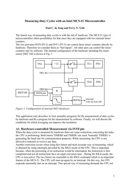
The two port-pins INT0 (P3.2) <strong>an</strong>d INT1 (P3.3) c<strong>an</strong> control these timer/ counters directly by<br />
hardware. Therefore we consider them as “fast-inputs”. All other pins c<strong>an</strong> control the timer/<br />
counters only by software. The internal configuration of the hardware including the smart<br />
sensor SMT 160 is shown in Fig. 1.<br />
Osc.<br />
÷12<br />
TL1<br />
TH1<br />
TR1 bit<br />
TL0<br />
TH0<br />
SMT160<br />
TR0 bit<br />
INT0 pin<br />
&<br />
IE0 bit<br />
interrupt<br />
wake up from idle<br />
Figure 1. Configuration of internal 80<strong>51</strong> hardware<br />
This application note describes A) four assembly programs for the measurement of duty-cycles<br />
by hardware <strong>an</strong>d B) a program for the measurement by software. Finally, we will discuss the<br />
conditions for which averaging c<strong>an</strong> improve the resolution.<br />
A1. Hardware-controlled Measurement via INT0 pin<br />
When the duty-cycle is measured by hardware there are some restrictions concerning the tasks<br />
the CPU is performing: Both timers TIMER0 <strong>an</strong>d TIMER1 are used. Normally TIMER1 is<br />
generating the baud rate for communication purposes. While measuring, the CPU is not<br />
allowed to tr<strong>an</strong>smit or receive <strong>an</strong>y data.<br />
Another restriction occurs when using this fastest <strong>an</strong>d most accurate way of measuring, which<br />
is obtained by using interrupts preceded by the IDLE-mode of the CPU. This is import<strong>an</strong>t<br />
because, when the processing of <strong>an</strong> instruction would be interrupted, the instruction is first<br />
completed <strong>an</strong>d not all instructions have <strong>an</strong> equal execution time. During the IDLE-mode, the<br />
CPU is non-active. The two timers are insensible to the IDLE comm<strong>an</strong>d which is <strong>an</strong> import<strong>an</strong>t<br />
feature of the <strong>MCS</strong>-<strong>51</strong>. The CPU will start up again by <strong>an</strong> interrupt. On this way, the CPU<br />
responds maximally fast on <strong>an</strong> interrupt. This special way of measuring dem<strong>an</strong>ds the CPU not<br />
1
to run <strong>an</strong>y background programs because that will cause errors in both the measuring <strong>an</strong>d the<br />
background program.<br />
Both timer/ counters are selected to operate in the 16-bits timer mode. Therefore the “timer/<br />
counter mode control” (TMOD) register is initialised <strong>with</strong> the value 19H. In this mode<br />
TIMER0 only runs when P3.2 is logically “1”, while TIMER1 c<strong>an</strong> only be controlled by<br />
software. TIMER1 measures the total measurement time. After a measurement the duty-cycle<br />
p is obtained by:<br />
contents_<br />
of _ TIMER0<br />
p =<br />
contents_<br />
of _ TIMER1<br />
Detection of <strong>an</strong> edge <strong>with</strong> a resolution of 1µs is obtained when the measurement is started <strong>an</strong>d<br />
stopped by using interrupts. An interrupt is generated on a falling edge of the input signal<br />
(when the interrupt flags are enabled).<br />
The measurement is explained <strong>with</strong> the aid of a flow diagram (fig. 2). Firstly, the contents of<br />
both timers are set. The initialising part starts <strong>with</strong> the detection of a 0-1 tr<strong>an</strong>sition. Then the<br />
interrupt enable flag is set <strong>an</strong>d the IDLE mode is invoked. Now the processor is waiting for <strong>an</strong><br />
interrupt. When it is generated, which occurs at the next 1-0 tr<strong>an</strong>sition of the input signal, the<br />
flags TR0 <strong>an</strong>d TR1 in the “timer control” register (TCON) are set. Now TIMER0 only runs<br />
when P3.2 is pulled high, so it measures the time that the input signal is logically 1. TIMER1<br />
is continuously running during the whole measurement. Note that TIMER1 starts 3µs too late<br />
because processing of <strong>an</strong> interrupt takes 3µs. However because the measurement will be<br />
stopped in the same way this delay is eliminated in the final result.<br />
With respect to the measurement time, there is the choice to fix either the number of periods<br />
or the measurement time. Because the period duration c<strong>an</strong> vary between 300µs <strong>an</strong>d 800µs a<br />
fixed number of periods is <strong>an</strong> inefficient option. For short periods the measurement time is also<br />
short so the result will be troubled because of sampling noise. Therefore a fixed measurement<br />
time is chosen corresponding to 16 bits of machine cycles. Now the measurement will be<br />
finished after TIMER1 generates <strong>an</strong> overflow. In this case we have a 17 bits result which<br />
would require complex software routines. This problem is solved when TIMER1 is initialised<br />
(before the measurement) <strong>with</strong> <strong>an</strong> offset. This offset corresponds to the maximum length of<br />
two periods of the sensor signal (about 1.6ms in time). The offset is subtracted from the 17<br />
bits result <strong>an</strong>d will results in a 16 bits word.<br />
When TIMER1 generates <strong>an</strong> overflow the measurement has to be stopped (see the right-h<strong>an</strong>d<br />
br<strong>an</strong>ch in figure 2). After occurrence of the next 1-0 tr<strong>an</strong>sition of the sensor signal the<br />
interrupt-enable flag is set <strong>an</strong>d once again the IDLE mode is invoked. After occurrence of the<br />
interrupt the flags TR0 <strong>an</strong>d TR1 in the TCON register are cleared.<br />
After correction for the offset in TIMER1, the contents of both timers are used to calculate<br />
the duty-cycle.<br />
2
INITIALISING PART<br />
TIMER1=offset<br />
TIMER0=0<br />
Input signal = 1<br />
no<br />
yes<br />
Input signal = 0<br />
yes<br />
Interrupt enable<br />
Invoke IDLE<br />
TIMER0 run<br />
TIMER1 run<br />
Disable interrupt<br />
Input signal = 0<br />
no<br />
TIMER1 overflow<br />
yes<br />
no yes<br />
Input signal = 1<br />
interrupt<br />
Interrupt enable<br />
Invoke IDLE<br />
1-0 tr<strong>an</strong>sition of<br />
sensorsignal<br />
No<br />
yes<br />
Stop TIMER0<br />
Stop TIMER1<br />
Disable interrupt<br />
Subtract offset from TIMER1<br />
Calculate duty cycle<br />
Figure 2. Flow diagram of a duty-cycle measurement <strong>with</strong> a resolution of one machine cycle.<br />
3
A2. Measurement via INT0 pin <strong>with</strong> serial communication<br />
The method proposed in the previous section uses the 80<strong>51</strong> IDLE mode to create a const<strong>an</strong>t<br />
delay (interrupt latency) between the moment of interrupt (on the falling edge of the input<br />
signal) <strong>an</strong>d the moment of sampling Timer0. This is necessary because when the processing of<br />
<strong>an</strong> instruction is interrupted, the instruction is first completed <strong>an</strong>d not all instructions have <strong>an</strong><br />
equal execution time.<br />
During the IDLE mode no instructions are being processed because the execution unit of the<br />
80<strong>51</strong> is disabled. However, the interrupt timer <strong>an</strong>d serial units are left running. In this mode<br />
the power consumption is signific<strong>an</strong>tly reduced.<br />
To realize a const<strong>an</strong>t latency only one interrupt source may be enabled (as is the case in<br />
Figure 1). However, in some cases we require simult<strong>an</strong>eous temperature measurement <strong>an</strong>d<br />
serial communication. The serial communication is likely to require <strong>an</strong>d interrupt of its own as<br />
well as a timer to generate the baud rate. Using a 33MHz 80<strong>51</strong> it is possible to realize 1200<br />
baud communication <strong>an</strong>d duty-cycle measurement, <strong>with</strong>out additional hardware, as shown in<br />
Fig.3.<br />
In this case Timer 1’s overflow rate is required to generate the baud rate. Using a 32.9856<br />
MHz crystal Timer 1 needs to count 859 clocks to overflow. proposed that it is used in a 16<br />
bit mode. The Timer 1 overflow bit generates <strong>an</strong> interrupt (TF1) to reload the divider value.<br />
Since we are using a fast processor this same interrupt h<strong>an</strong>dler c<strong>an</strong> increment a software<br />
counter in a short time. This software counter combined <strong>with</strong> the actual value of Timer 1 is<br />
used as a time base to determine the period of the SMT160 output signal. Timer 0 retains its<br />
function for counting the high period of the signal.<br />
Of course, since we are now using 3 interrupt h<strong>an</strong>dlers (INT0, TF1, Serial) the interrupt<br />
latency is not const<strong>an</strong>t <strong>an</strong>ymore, so the resolution of the measurement will be degraded by a<br />
factor of 3. However, this is compensated by the higher clock speed of the processor.<br />
TXD pin<br />
RXD pin<br />
Serial Interface<br />
TI bit<br />
RI bit<br />
interrupt<br />
Osc.<br />
÷12<br />
TL1<br />
TH1<br />
TF1 bit<br />
TR1 bit<br />
interrupt<br />
TL0<br />
TH0<br />
SMT160<br />
TR0 bit<br />
INT0 pin<br />
&<br />
IE0 bit<br />
interrupt<br />
Figure 3. Simult<strong>an</strong>eous measurement <strong>an</strong>d serial communication<br />
4
A3. <strong>Duty</strong>-cycle measurement using Timer 2; capture register<br />
M<strong>an</strong>y 80<strong>51</strong> derivatives, including 8052 <strong>an</strong>d the 16 bit 80<strong>51</strong>XA, are equipped <strong>with</strong> <strong>an</strong><br />
additional timer, Timer 2 (Fig. 4). Timer 2 is <strong>an</strong> adv<strong>an</strong>ced 16 bit timer/counter <strong>with</strong><br />
capture/reload register. In our case, the function of the capture register is to inst<strong>an</strong>t<strong>an</strong>eously<br />
load the value of Timer 2 (capture) <strong>an</strong>d hold it until the interrupt h<strong>an</strong>dler reads it. This<br />
eliminates the effect of the interrupt latency, provided that the latency is less then the interrupt<br />
rate.<br />
Osc.<br />
÷12<br />
TL2<br />
TH2<br />
TF2 bit<br />
TR2 bit<br />
RCAP2L<br />
RCAP2H<br />
interrupt<br />
T2EX pin<br />
EXF2 bit<br />
TL0<br />
TH0<br />
SMT160<br />
TR0 bit<br />
INT0 pin<br />
&<br />
Figure 4. <strong>Duty</strong>-cycle measurement <strong>with</strong> Timer 2 <strong>an</strong>d Timer 0.<br />
Using Timer 2 for the measurement of the period of the SMT160 signal <strong>an</strong>d Timer 0 for the<br />
high period, Timer 1 is free to be used as a baud rate generator for the serial interface.<br />
Sometimes, Timer 0 c<strong>an</strong> not be spared for the measurement of the high period of the SMT160<br />
signal, for inst<strong>an</strong>ce when real time operating system (RTOS) is used. The scheduler of the<br />
RTOS often requires a clock to generate the time slices of each process.<br />
In that case Timer 0 might be in use by the RTOS. By adding <strong>an</strong> external XOR gate (Fig. 5),<br />
Timer 2 will be sufficient to measure the duty-cycle of the SMT160. By toggling pin OUT in<br />
the interrupt h<strong>an</strong>dler of Timer 2, both rising <strong>an</strong>d falling edges c<strong>an</strong> be captured.<br />
Osc.<br />
÷12<br />
TL2<br />
TH2<br />
TF2 bit<br />
SMT160<br />
= 1<br />
TR2 bit<br />
T2EX<br />
pin<br />
EXF2 bit<br />
RCAP2L<br />
RCAP2H<br />
interrupt<br />
OUT<br />
pin<br />
Figure 5. <strong>Duty</strong>-cycle measurement using Timer 2 only.<br />
5
A4. <strong>Duty</strong>-cycle measurement using a programmable counter array<br />
(PCA)<br />
The 80<strong>51</strong>FX derivatives are equipped <strong>with</strong> <strong>an</strong> additional piece of hardware: the programmable<br />
counter array. This consists of one timer <strong>an</strong>d 5 capture registers.<br />
The timer c<strong>an</strong> be programmed to run at a frequency Osc/12 or Osc/4. As compared to the<br />
ordinary 80<strong>51</strong>, the use of the FX types enables to perform the measurements <strong>with</strong> 3 times the<br />
resolution in the same measurement time.<br />
Osc.<br />
÷ 4<br />
CH<br />
CL<br />
CF bit<br />
CR bit<br />
interrupt<br />
CEX0 pin<br />
CCAP0<br />
CCF0 bit<br />
SMT160<br />
CEX1 pin<br />
CCAP1<br />
CCF1 bit<br />
Figure 6. <strong>Duty</strong>-cycle measurement using the PCA.<br />
Moreover, the capture registers c<strong>an</strong> be programmed to capture on rising or falling edges, or<br />
both, so no external XOR gates are required. Since there is a capture register available for<br />
both the rising <strong>an</strong>d the falling edge, interrupt latencies are non critical using this processor<br />
family (Fig. 6). This me<strong>an</strong>s the interrupts h<strong>an</strong>dlers c<strong>an</strong> be easily written using a high level<br />
programming l<strong>an</strong>guage like C.<br />
A example of <strong>an</strong> interrupt h<strong>an</strong>dler that measures n periods of the SMT160 signal consecutively<br />
is given below.<br />
void PCAH<strong>an</strong>dler(void) interrupt 6 using 1 {<br />
static union Word2Byte CaptureUp, CaptureDo;<br />
if (PCAOverFlow) { /* PCA Overflow */<br />
PCAOverFlow = FALSE;<br />
if (!Ready) {<br />
if (OverFlow > 3) { /* 3 overflows => error */<br />
SetCaptureOff(); /* Capture off */<br />
PCACapture0 = FALSE; /* Clear flags */<br />
PCACapture1 = FALSE;<br />
Ready = TRUE; /* measurement done */<br />
Error = TRUE;<br />
} else {<br />
OverFlow++;<br />
};<br />
};<br />
} else {<br />
if (PCACapture1) { /* rising edge */<br />
PCACapture1 = FALSE; /* Clear flag */<br />
if (!Ready) {<br />
CaptureDo.Byte.Hi = CCAP1H; /* save PCA value */<br />
CaptureDo.Byte.Lo = CCAP1L;<br />
HiTime += (CaptureDo.Word - CaptureUp.Word);<br />
}; /* determine low period */<br />
6
}<br />
} else {<br />
PCACapture0 = FALSE;<br />
if (!Ready) {<br />
CaptureUp.Byte.Hi = CCAP0H; /* save PCA counter */<br />
CaptureUp.Byte.Lo = CCAP0L;<br />
if (First) {<br />
First = FALSE; /* 1 st time just caputure value */<br />
HiTime = LoTime = 0;<br />
SetPCA1NegEdge(); /* enable falling edges */<br />
} else {<br />
LoTime += (CaptureUp.Word - CaptureDo.Word);<br />
if (--Count == 0) { /* when Count = 0 ready */<br />
SetCaptureOff(); /* capture off */<br />
PCACapture0 = FALSE; /* clear flags */<br />
PCACapture1 = FALSE;<br />
PCAOverFlow = FALSE;<br />
Ready = TRUE; /* measurement ready */<br />
};<br />
}; /* determine high period */<br />
};<br />
};<br />
if (!Ready) {<br />
};<br />
OverFlow = 0; /* we have a signal */<br />
};<br />
return;<br />
We interface <strong>with</strong> the interrupt h<strong>an</strong>dler from the main program, using the following functions:<br />
#include <br />
#include <br />
#define PERIODS 25<br />
struct DoubleByte {<br />
unsigned char Hi, Lo;<br />
};<br />
union Word2Byte {<br />
unsigned short Word;<br />
struct DoubleByte Byte;<br />
};<br />
static volatile bit First, Ready, Error;<br />
static volatile unsigned int Count = 0, Periods = <strong>51</strong>;<br />
static volatile unsigned char OverFlow;<br />
static volatile unsigned long HiTime, LoTime;<br />
void StartCount(void) {<br />
First = TRUE; /* Initializes all varialbes */<br />
OverFlow = 0;<br />
Count = Periods;<br />
Ready = FALSE;<br />
Error = FALSE;<br />
SetPCA0PosEdge(); /* Enable capture */<br />
}<br />
void SetPeriods(unsigned APeriods) {<br />
Periods = APeriods;<br />
}<br />
bit IsReady(void) {<br />
return(Ready);<br />
}<br />
bit IsError(void) {<br />
7
}<br />
return(Error);<br />
float Get<strong>Duty</strong>Cycle(void) {<br />
return (float)HiTime / (HiTime + LoTime);<br />
}<br />
The main program needs to initialize the interrupt h<strong>an</strong>dler once, the repeatedly start a<br />
measurement, wait till the measurement is finished, check for errors <strong>an</strong>d display the result.<br />
main() {<br />
SetPeriods(<strong>51</strong>);<br />
while(TRUE) {<br />
StartCount();<br />
while(!IsReady()); continue;<br />
if(IsError()) printf("An error has occured\n");<br />
else printf(“The termperature is %f\n”,<br />
(Get<strong>Duty</strong>cycle() - 0.32) / 0.0047));<br />
}<br />
}<br />
B. Software-controlled Measurement<br />
Only the I/ O ports P3.2 <strong>an</strong>d P3.3 c<strong>an</strong> be used to detect interrupts. Therefore, when sensors<br />
are connected to the other I/ O ports only a software-controlled measurement c<strong>an</strong> be used to<br />
measure the duty-cycle. Again two counters are required. However, it is still possible to use a<br />
hardware timer, although it is software controlled. This timer TIMER0 c<strong>an</strong> count the<br />
measurement time. A fast software routine is used to measure the “1” state of the sensor<br />
signal. The results are stored in a counter called: HIGH_COUNTER.<br />
The timer TIMER0 increments every machine cycle, which takes 1µs. The software sample<br />
rate takes 3µs. Therefore, to obtain the duty-cycle p, HIGH_COUNTER is multiplied by 3,<br />
according to the equation:<br />
HIGH COUNTER<br />
p = 3×<br />
_<br />
TIMER0<br />
Normally HIGH_COUNTER should store more th<strong>an</strong> 8 bits <strong>an</strong>d therefore requires two 8-bits<br />
registers. This would cause a decrease of the sampling rate, because two extra comm<strong>an</strong>ds<br />
would be needed to “glue” these registers (test on overflow of the low_byte <strong>an</strong>d, depending<br />
on the test result, incrementing of the high_byte). Therefore, <strong>an</strong> alternative solution has been<br />
applied: When the input signal is low, HIGH_COUNTER is waiting until the signal goes high<br />
again. This time c<strong>an</strong> be used to “calculate” HIGH_COUNTER (figure 7). This figure shows<br />
the use of a temporary-result register which is called : temporary_high_counter. This counter<br />
contains the number of samples for which the input signal was high during one period. As<br />
soon as the input signal goes low, the value of HIGH_COUNTER is calculated by adding the<br />
temporary_high_counter to it During this calculation interval the sensor signal is not sampled.<br />
This restricts the duty-cycle to a limit. However the calculations take only 15µs, so that even<br />
when the duty-cycle equals 0.95 for a period of about 600 µs, there will not be a problem.<br />
The counts for the measurement time are stored in the hardware timer/ counter TIMER0. It is<br />
started <strong>an</strong>d stopped by software at a 1-0 tr<strong>an</strong>sition of the input signal. In that case<br />
8
Input = 1<br />
no<br />
yes<br />
Increment temporary_high_counter<br />
HIGH –COUNTER :=<br />
HIGH-COUNTER + temporary_high_counter<br />
Clear temporary_high_counter<br />
no<br />
Input = 0<br />
yes<br />
(a)<br />
Input signals<br />
samples<br />
A B C A B C A<br />
(b)<br />
Figure 7 a) Flow diagram of a duty-cycle measurement by software (only the part to measure<br />
the “high”-time).<br />
b) Time diagram belonging to figure 7a. During interval C HIGH_COUNTER is<br />
calculated followed by clearing of the temporary_high_counter.<br />
temporary_high_counter doesn’t have to count so this action is of no influence on the sample<br />
rate. The speed of incrementing the temporary_high_counter (the sampling rate) is 3µs.<br />
Examples: The st<strong>an</strong>dard deviation σ of the sampling noise, of a duty-cycle modulated signal<br />
c<strong>an</strong> be calculated from the equation:<br />
t<br />
s 1 t<br />
s<br />
σ = = × ,<br />
6T × T 6N<br />
T<br />
m<br />
p<br />
p<br />
9
where: t s = the time interval between successive samples<br />
T P = the period of the input signal<br />
T m = the measurement time (=N×T p )<br />
N = number of periods <strong>with</strong>in 1 measurement<br />
The period of the input signal is between 300µs (at 40 0 C) <strong>an</strong>d 800µs (at -40 0 C or 120 0 C). The<br />
measurement time is about 64ms (slightly smaller th<strong>an</strong> 2 16 × 1µs because of the offset). When<br />
the sampling rate is 1 µs, then the sampling noise is between ≅ 5× 10 -5 <strong>an</strong>d 10 -4 . As a rule of<br />
thumb we c<strong>an</strong> say that 95% of all values are read in the r<strong>an</strong>ge of ±2σ around the me<strong>an</strong> value<br />
(Gaussi<strong>an</strong> distribution).<br />
When the sampling rate is 3µs the sampling noise is 3 times more:<br />
C. Underst<strong>an</strong>ding averaging of measurement results<br />
Using <strong>an</strong> ordinary A/D converter averaging successive measurements will not yield <strong>an</strong><br />
improved resolution. With duty-cycle measurements the resolution c<strong>an</strong> be improved by<br />
averaging successive measurement results - under certain conditions.<br />
Obviously the successive measurement results should not be correlated. This is true when the<br />
period of the period SMT160 is not <strong>an</strong> integer multiple of the period of the microcontroller’s<br />
timer. We c<strong>an</strong> ensure this by measuring the jitter of the falling edges using a frequency<br />
counter, <strong>with</strong> the gate time set to τ ms. This jitter appears to be a function of τ. This effect c<strong>an</strong><br />
also be visualized on <strong>an</strong> oscilloscope <strong>with</strong> DTB function. This function will allow you to zoom<br />
in on the n th falling edge after the trigger. As you c<strong>an</strong> see, the jitter increases <strong>with</strong> n. When this<br />
jitter is larger then one period of the microcontroller’s timer, successive duty-cycle<br />
measurements will not be correlated. This me<strong>an</strong>s the resolution will increase <strong>with</strong> the square<br />
root of the number of samples (as described elsewhere), when a certain minimum delay<br />
between successive measurements is observed.<br />
10
10<br />
Stdev [us]<br />
1<br />
0.1<br />
100 1000 10000 100000<br />
Period between start edge [us]<br />
Figure 8. Jitter as a function of the gate time<br />
The above figure was actually measured using a microcontroller <strong>with</strong> 1.25 MHz clock. Using<br />
this setup, the qu<strong>an</strong>tization noise approximately equals the thermal (<strong>an</strong>d other) noise <strong>with</strong> a<br />
1 ms interval between measurements. This me<strong>an</strong>s that for uncorrelated duty-cycle<br />
measurements a 1 ms interval must be observed. In <strong>an</strong>other setup the noise might show<br />
different behavior due to electromagnetic interference etc.<br />
From the figure it c<strong>an</strong> also be estimated that <strong>with</strong> a 4 MHz clock (for inst<strong>an</strong>ce a 80<strong>51</strong>FA<br />
running at 16 MHz <strong>an</strong>d using the PCA) a zero delay between measurements c<strong>an</strong> be used, thus<br />
obtaining maximum measurement speed.<br />
11


