Unison Research P70 White Paper - VMAX Services
Unison Research P70 White Paper - VMAX Services
Unison Research P70 White Paper - VMAX Services

Create successful ePaper yourself
Turn your PDF publications into a flip-book with our unique Google optimized e-Paper software.
<strong>Unison</strong> <strong>Research</strong><br />
<strong>P70</strong><br />
Fully balanced dual mono<br />
valves Amplifier in Push-Pull<br />
topology<br />
Why a push-pull amplifier<br />
A push-pull topology amplifier is characterised by a power stage in which<br />
active devices pairs work together amplifying separately the positive and the<br />
negative signal half waves. The output transformer, with its particular<br />
structure, reconstructs the amplified signal and makes it available at the<br />
output terminals.<br />
The main benefit of this topology is the possibility to design amplifiers which<br />
have a much higher power than their single-ended counterparts, using the<br />
same power valves in the output stage.<br />
This advantage reflects in a better efficiency, which also means a significant<br />
reduction of the dissipated heat at the same power rate.<br />
Nonetheless the push-pull stages, because of to the simultaneous action of two<br />
different devices, needs a very careful design and set up to avoid the large<br />
distortion that always occurs when the amplification of the two half waves is<br />
not equal.
A bit of history...<br />
In the past <strong>Unison</strong> <strong>Research</strong> had designed and produced different push-pull<br />
models, mainly because it was complicated and expensive to obtain large<br />
output power with single-ended stages. Among the others let us mention the<br />
Triode 20, the Power 35 and the early Nimbly.<br />
The <strong>P70</strong><br />
Designing the <strong>P70</strong> has required about one year of work. The very first<br />
prototype has been developed in 2006, and it immediately showed all the<br />
critical elements related with this kind of design. It took time to find all the<br />
electronic solutions that have lead to the current cirquitry.<br />
The <strong>P70</strong> is now an amplifier capable of delivering more than 70 W per<br />
channel into a 6Ohm load, with a THD lower than 0,2% over the whole audio<br />
band. Its performances are comparable to those of a good single ended<br />
amplifier.<br />
Structure of the amplifier<br />
The amplifier is laid out in dual mono configuration. Both the amplifier stages<br />
and the power supply circuits are completely independent.<br />
The signal path in the amplifier is fully balanced from the input through the<br />
output. This means that the signal at the output terminals is balanced with<br />
respect to the amplifier ground.<br />
The <strong>P70</strong> has four line inputs. All of them can be balanced or unbalanced, an<br />
external switch allows the selection. The volume potentiometer is a four<br />
sections motorised Alps blue series potentiometer. The selection of the<br />
channel is performed by four high quality relè.
All the operations of the amplifier, included the safety functions, are<br />
controlled by a microprocessor to ensure maximum reliability and intuitive<br />
user interface.<br />
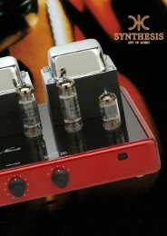
The amplifier itself is constituted by an input stage featuring two double<br />
triodes ECC83 and one double triode ECC82, and a power stage with two<br />
KT88 per channel.<br />
The output transformer has been custom designed by <strong>Unison</strong> <strong>Research</strong> and<br />
ensure a bandwidth of more than 30kHz at full power.<br />
The design<br />
During the development of the first prototype, we had the possibility to<br />
observe and analyse how the push-pull power stage requires a driving current<br />
significantly higher and differently shaped than that of a single ended power<br />
stage. Thus we concentrated our efforts in redesigning the circuit so to keep<br />
the output impedance as low as possible.<br />
Another point that has required special care is the polarization of the whole<br />
output stage, which had to be stable enough to sustain the large signal<br />
excursions required to properly drive the stage under the most critical<br />
operating conditions.<br />
The preamplifier is constituted by a double differential pair in an original<br />
configuration. The two differential stages are DC coupled and allow to reach<br />
the needed gain. They are followed by a couple of cathode followers, again<br />
DC coupled, which guarantee the low output impedance required.<br />
The power supply for the whole preamplifier stage has a very high voltage,<br />
around 600V.
The input stage has a local feedback, characterised by different feedback<br />
factors for the bias component and the signal. The two different values are set<br />
keeping into account the different need for precision on the value of the bias<br />
and of the signal.<br />
The importance of a stable controlled bias in the amplifier is due first of all to<br />
the choice of the DC coupling between the stages and also to the need to<br />
allow the same signal excursion along the paths of the balanced signal.<br />
The circuit we have designed amplifies signals up to 200V pp.<br />
Conversely, the feedback factor affecting the signal has been kept to the<br />
lowest possible value.<br />
It worth mentioning that the particular circuit configuration chosen and the<br />
presence of a double differential stage guarantee the possibility to use the<br />
amplifier also with unbalanced signals. The proper connection can easily be<br />
done through the input terminals on the back.<br />
Finally, the signal is feedback in a balanced way to the cathodes of the input<br />
differential stage, as in a traditional triode amplifier.<br />
The power stage is constituted by a couple of KT88 per channel. During the<br />
set up, we have considered that a bias current of about 50mA allows an<br />
adequate trade-off between maximum power, distortion and power<br />
dissipation.<br />
We have also observed how, in most of the traditional push-pull stages<br />
solutions, the level of the bias is hardly constant when the input signal or the<br />
power supply voltage changes, and this makes the tube work, although for<br />
short times, in interdiction or over-bias condition.
Moreover, these schemes often require a manual “tuning” of the bias current<br />
and the balancing of the currents in the two paths that has to be performed<br />
with the amplifier warm and fully working.<br />
To solve this problem, in the <strong>P70</strong> a brand new circuit has been designed,<br />
which ensures a constant bias level with respect either to variations of the<br />
input signal or the power supply, or in overload conditions, or to variations of<br />
the tubes characteristics due to ageing.<br />
The correct polarization is reached immediately after switching on, even<br />
though the amplifier has not yet reached the optimal operating temperature.<br />
This circuit continuously verifies the bias current level and the currents in the<br />
push-pull paths, and automatically provides the eventual needed corrections.<br />
The user doesn’t have to manually tune the bias, even after the KT88 pair has<br />
been replaced.<br />
We are considering to have this solution patented.<br />
As far as concerning the power supply, according to the dual mono lay-out<br />
already mentioned, there are two completely independent circuits.<br />
It has a first filtering stage entrusted to a couple of high voltage p<br />
configuration LC filter for the 650V of the power stage supply.<br />
The second filtering stage is entrusted to a couple of high voltage p<br />
configuration RC filters for the 600V of the amplifier stage supply.<br />
The tube heaters power supply has a regulated DC voltage.<br />
Another negative voltage is regulated to provide the bias of the KT88.
Technical data:<br />
Power Output:<br />
70W + 70W RMS<br />
Output Impedance:<br />
6 Ohms (4-8 Ohms)<br />
Input Sensitivity:<br />
500 mV<br />
Input impedance:<br />
47 KOhms<br />
Frequency Response: 10 Hz to 40 Khz (0.5 dB 1W)<br />
Signal/Noisse Ratio:<br />
83 dBA<br />
Total Harmonic Distortion:<br />
0.3% (10W)<br />
Negative Feedback:<br />
12 dB<br />
Damping factor: 8<br />
CMRR:<br />
59 dB<br />
Power Requirements:<br />
105-120/210-240V (50-60 Hz) at rest 360W<br />
Dimension (WxDxH):<br />
460x450x200 mm<br />
Weight:<br />
35 Kg