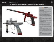
JT Impulse maintenance and operation manual - Paintball Solutions
JT Impulse maintenance and operation manual - Paintball Solutions
JT Impulse maintenance and operation manual - Paintball Solutions

You also want an ePaper? Increase the reach of your titles
YUMPU automatically turns print PDFs into web optimized ePapers that Google loves.
1<br />
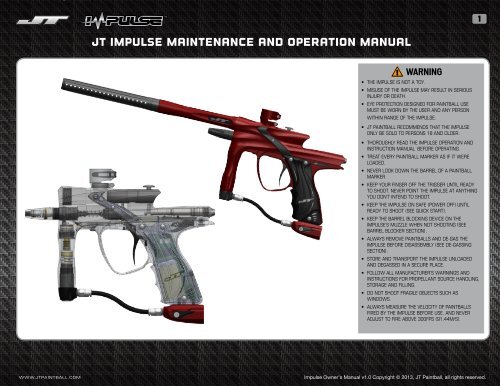
<strong>JT</strong> <strong>Impulse</strong> <strong>maintenance</strong> <strong>and</strong> <strong>operation</strong> <strong>manual</strong><br />
WARNING<br />
• THE <strong>Impulse</strong> IS NOT A TOY.<br />
• MISUSE OF THE <strong>Impulse</strong> MAY RESULT IN SERIOUS<br />
INJURY OR DEATH.<br />
• EYE PROTECTION DESIGNED FOR PAINTBALL USE<br />
MUST BE WORN BY THE USER AND ANY PERSON<br />
WITHIN RANGE OF THE <strong>Impulse</strong>.<br />
• <strong>JT</strong> PAINTBALL RECOMMENDS THAT THE <strong>Impulse</strong><br />
ONLY BE SOLD TO PERSONS 18 AND OLDER.<br />
• THOROUGHLY READ THE <strong>Impulse</strong> OPERATION AND<br />
INSTRUCTION MANUAL BEFORE OPERATING.<br />
• TREAT EVERY PAINTBALL MARKER AS IF IT WERE<br />
LOADED.<br />
• NEVER LOOK DOWN THE BARREL OF A PAINTBALL<br />
MARKER.<br />
• KEEP YOUR FINGER OFF THE TRIGGER UNTIL READY<br />
TO SHOOT. NEVER POINT THE <strong>Impulse</strong> AT ANYTHING<br />
YOU DON’T INTEND TO SHOOT.<br />
• KEEP THE <strong>Impulse</strong> ON SAFE (POWER OFF) UNTIL<br />
READY TO SHOOT (SEE QUICK START).<br />
• KEEP THE BARREL BLOCKING DEVICE ON THE<br />
<strong>Impulse</strong>’S MUZZLE WHEN NOT SHOOTING (SEE<br />
BARREL BLOCKER SECTION).<br />
• ALWAYS REMOVE PAINTBALLS AND DE-GAS THE<br />
<strong>Impulse</strong> BEFORE DISASSEMBLY (SEE DE-GASSING<br />
SECTION).<br />
• STORE AND TRANSPORT THE <strong>Impulse</strong> UNLOADED<br />
AND DEGASSED IN A SECURE PLACE.<br />
• FOLLOW ALL MANUFACTURER’S WARNINGS AND<br />
INSTRUCTIONS FOR PROPELLANT SOURCE HANDLING,<br />
STORAGE AND FILLING.<br />
• DO NOT SHOOT FRAGILE OBJECTS SUCH AS<br />
WINDOWS.<br />
• ALWAYS MEASURE THE VELOCITY OF PAINTBALLS<br />
FIRED BY THE <strong>Impulse</strong> BEFORE USE, AND NEVER<br />
ADJUST TO FIRE ABOVE 300FPS (91.44M/S).<br />
WWW.<strong>JT</strong>PAINTBALL.COM<br />
<strong>Impulse</strong> Owner’s Manual v1.0 Copyright © 2013, <strong>JT</strong> <strong>Paintball</strong>, all rights reserved.
Barrel Blocker / Battery<br />
2<br />
Barrel Blocker<br />
alkaline battery<br />
Barrel Blocker The barrel blocker is a very important piece of safety equipment – as important as goggles. It is used any time the <strong>Impulse</strong> (or<br />
any other paintball marker) is connected to an air source <strong>and</strong> is in an area where people are not protected by paintball goggles or paintball field<br />
netting.<br />
The barrel blocker performs a very simple function. If the <strong>Impulse</strong> is accidentally fired, the barrel blocker catches the paintball to prevent accidental<br />
injury or damage. Although turning off the <strong>Impulse</strong> does serve as a safety mechanism to prevent it from firing, the barrel blocker has an advantage<br />
in that it is clearly visible to everyone that it is in use. It is important to make sure that the barrel blocker is securely in place when it is used. To<br />
put the barrel blocker on the <strong>Impulse</strong>, slide it over the end of the barrel <strong>and</strong> loop the cords over the back of the marker. Adjust the cord lock so<br />
that the barrel blocker is held snugly in place <strong>and</strong> cannot slip free.<br />
Pro Tip: Because the barrel<br />
blocker is visible to everyone <strong>and</strong><br />
works with all markers, it is the<br />
st<strong>and</strong>ard safety device used any<br />
time the <strong>Impulse</strong> is h<strong>and</strong>led in<br />
safe zones where goggles are<br />
off.<br />
Battery The electronic components in the <strong>Impulse</strong> are powered by a single rectangular 9-volt battery. For optimal performance, alkaline batteries<br />
(ANSI type 1604A) should be used. Lower cost “heavy duty” zinc/carbon batteries do not last nearly as long, or deliver amperage as reliably <strong>and</strong><br />
should be avoided. Most “9v” style rechargeable batteries will work with the <strong>Impulse</strong>, but their charge levels may not be accurately reported on the<br />
<strong>Impulse</strong> display. It is advisable to gain experience with any particular rechargeable battery before trusting an important game to it.<br />
Installing or changing the battery in the <strong>Impulse</strong> is simple. Use a 5/64-inch allen wrench to remove the two grip screws from the left side of the<br />
marker <strong>and</strong> open the rubber grip. The battery simply slides into place, contact side up. Battery orientation is important. The positive terminal of<br />
the battery (smaller of the two snap conectors) should be aligned towards the <strong>Impulse</strong> display screen, while the negative terminal (larger snap)<br />
should be towards the barrel. With the battery in place, close the grip <strong>and</strong> secure it with the two grip screws. Make sure the circuit board’s<br />
battery contacts are pressed firmly under spring pressure against the battery terminals. If the fit is loose, slight bending of the contacts may<br />
be necessary. Because the <strong>Impulse</strong> circuit board draws a very small amount of current from the battery even when it is turned off, it is best to<br />
remove the battery if the marker is going to be stored for a few weeks or more.<br />
WWW.<strong>JT</strong>PAINTBALL.COM<br />
<strong>Impulse</strong> Owner’s Manual v1.0 Copyright © 2013, <strong>JT</strong> <strong>Paintball</strong>, all rights reserved.
compressed air<br />
3<br />
ASA OFF ASA On ASA LOCK SCREW<br />
HPA The <strong>Impulse</strong> is designed to be powered by a high pressure compressed air (HPA) system only. Use of carbon dioxide (CO2) to power the<br />
<strong>Impulse</strong> is likely to cause damage to sensitive internal seals <strong>and</strong> will result in a voided warranty.<br />
<strong>Paintball</strong> HPA systems consist of an air storage cylinder rated to 3,000 psi or 4,500 psi <strong>and</strong> an integrated regulator/valve installed in the neck of<br />
the cylinder. HPA systems are typically divided into high-output (800 psi) <strong>and</strong> low-output (400 psi) models. Either type will work with the <strong>Impulse</strong>,<br />
though use of a high-output model will often deliver more consistent velocity at high rates of fire.<br />
HPA systems are shipped empty, <strong>and</strong> must be filled by properly trained persons. Once filled, the HPA system is attached to the <strong>Impulse</strong> by<br />
screwing it in to the bottom-line ASA (See ASA).<br />
ASA The <strong>Impulse</strong> is equipped with a bottom-line style venting on/off Air System Adapter (ASA). Before screwing an HPA system into the ASA,<br />
make sure the ASA is turned off by turning the on/off lever forward. After screwing in the HPA system, the ASA may be turned on by turning the<br />
on/off lever back parallel with the ASA body. The ASA lever should be turned on slowly, so that the gas pressure inside the <strong>Impulse</strong> rises gently,<br />
rather than with a sudden “pop.”<br />
WARNING: When removing<br />
an HPA System from the ASA<br />
watch carefully to make sure<br />
the HPA system regulator is unscrewing<br />
from the ASA <strong>and</strong> that<br />
the HPA cylinder is not unscrewing<br />
from the HPA regulator.<br />
WARNING: Never put oil or<br />
other hydrocarbon products in<br />
an HPA system or its fill nipple.<br />
When turning the ASA off, gas trapped between the ASA <strong>and</strong> vertical regulator will be released with a brief hissing sound. This is normal. Turning<br />
off the ASA does not completely de-pressurize the <strong>Impulse</strong> <strong>and</strong> may leave enough gas inside the marker to fire 2 or more shots (see de-gassing).<br />
The ASA may be replaced with other similar gas mounts or fittings. To replace the ASA, first unload <strong>and</strong> de-gas the marker, then remove the HPA<br />
system. Use a 3/32-inch allen wrench through the middle hole in the bottom of the grip frame to loosen the ASA setscrew. Temporary thread<br />
locking compound (Blue Loctite 242 or equivalent) is used to keep the ASA lock screw in place. The ASA may be replaced by one of a similar design<br />
which uses a 3/4-inch dovetail mounting rail, or an ASA which uses traditional center aligned 10-32 ASA mounting screws.<br />
WWW.<strong>JT</strong>PAINTBALL.COM<br />
<strong>Impulse</strong> Owner’s Manual v1.0 Copyright © 2013, <strong>JT</strong> <strong>Paintball</strong>, all rights reserved.
Paint / Hopper<br />
4<br />
FEEDNECK OPEN FEEDNECK CLAMPED FINE ADJUSTMENT<br />
Paint The <strong>Impulse</strong> is a high-end tournament grade paintball marker designed to give players the winning edge at all levels of competition from<br />
intense scenarios <strong>and</strong> weekend walk-on play to professional level tournaments. Getting top level performance out of the <strong>Impulse</strong> depends on using<br />
a top quality paintball. <strong>Paintball</strong>s which are old, misshapen, have been stored in hot areas or open containers will not work as well as fresh topgrade<br />
paint. Moreover the gentle bolt pressure <strong>and</strong> Vision anti-chop system in the <strong>Impulse</strong> are optimized to work well with thin <strong>and</strong> brittle shelled<br />
tournament grade paintballs that break more easily on their targets without breaking in the marker.<br />
Hopper / Feedneck The <strong>Impulse</strong> can only fire fast if it is loaded quickly with paintballs. Best performance will be achieved with force-feed loaders<br />
which actively drive paintballs into the marker each time it is fired. Due to its Vision anti-chop system <strong>and</strong> low bolt pressures the <strong>Impulse</strong> can also<br />
make use of agitating or even non-powered loaders without unusual risk of chopped or broken paintballs, but its rate of fire will be limited to how<br />
fast it receives paintballs from the loader.<br />
Pro Tip: Choosing the right<br />
hopper is critical to getting the<br />
best performance from your<br />
<strong>Impulse</strong>. Take a tip from the<br />
Pros - XSV uses <strong>JT</strong> <strong>and</strong> Empire<br />
hoppers exclusively because<br />
they are both fast <strong>and</strong> reliable.<br />
The lever-action clamping feedneck on the <strong>Impulse</strong> allows for quick removal or installation of a loader. Simply pull the lever away from the feedneck<br />
to open the clamp, releasing its grip.<br />
Due to differences in loader neck sizes, the feedneck may need adjustment. If the feed-neck will not clamp on to a loader’s feedneck with a<br />
reasonable amount of pressure on its latch, or doesn’t clamp tight enough, it can be adjusted for a perfect fit. Quick adjustments can be made by<br />
opening the lever <strong>and</strong> turning one full turn it to tighten or loosen its position on the clamp adjustment screw. Fine adjustments of less than a full<br />
turn may be made by using a 7/64-inch allen wrench to turn the clamp adjustment screw for a perfect fit.<br />
WWW.<strong>JT</strong>PAINTBALL.COM<br />
<strong>Impulse</strong> Owner’s Manual v1.0 Copyright © 2013, <strong>JT</strong> <strong>Paintball</strong>, all rights reserved.
Power / Firing / timer<br />
5<br />
power button Power On Game Timer in use<br />
Power Press <strong>and</strong> hold the power button for approximately one second (until the <strong>JT</strong> logo appears on the display screen) to turn on the <strong>Impulse</strong>.<br />
When the <strong>Impulse</strong> is on, it is “live” <strong>and</strong> ready to fire. The <strong>Impulse</strong> may be turned off by pressing <strong>and</strong> holding the power button for approximately two<br />
seconds (until the display screen goes dark).<br />
FIRING Once the <strong>Impulse</strong> is charged with gas <strong>and</strong> switched live, it may be fired by pulling the trigger. Turning the <strong>Impulse</strong> electronics on or off is<br />
the equivalent of setting the safety on a mechanical paintball marker. Like all safety mechanisms, it should used in addition to, not in place of a<br />
barrel blocker.<br />
Pro Tip: Take a few minutes to<br />
practice turning the <strong>Impulse</strong> on<br />
<strong>and</strong> off, as well as navigating its<br />
programming menu. Being more<br />
familiar with your equipment<br />
in advance will let you focus on<br />
your game at the field.<br />
When the <strong>Impulse</strong> is live, the display screen will show the approximate charge level of the battery, the tournament lock status (see programming)<br />
the Vision status, the currently selected firing mode <strong>and</strong> rate of fire cap (except in semi-automatic mode which is uncapped). In addition, if the<br />
game timer is engaged, the countdown timer will be displayed.<br />
Approximate battery charge level is indicated by anywhere from 0 to 5 bars being appearing in a battery symbol on the <strong>Impulse</strong> display screen.<br />
Be aware that many rechargeable batteries have different discharge characteristics than alkaline batteries. A lithium-ion battery for example may<br />
appear only partially full when freshly charged, <strong>and</strong> give the same reading before “emptying” rapidly at the end of its useful charge. If using any<br />
battery type other than alkaline, it is recommended to learn how it will interact with the <strong>Impulse</strong> charge level indicator before relying on it in a<br />
game.<br />
TIMER The <strong>Impulse</strong> game timer is set through trigger based programming (see programming). When the timer is engaged, the display screen<br />
will show the pre-set time value when the marker is turned on. Pulling the trigger to fire a shot at the beginning of a game starts the timer’s<br />
countdown. When the timer reaches 00:00 it will remain at 00:00. Turning the <strong>Impulse</strong> off then back on again resets the timer for the next game.<br />
WWW.<strong>JT</strong>PAINTBALL.COM<br />
<strong>Impulse</strong> Owner’s Manual v1.0 Copyright © 2013, <strong>JT</strong> <strong>Paintball</strong>, all rights reserved.
vision<br />
6<br />
Breech Empty breech full eye fault vision off<br />
Vision The <strong>Impulse</strong> is equipped with the latest generation Vision TM break-beam anti-chop eye system. Multiple Vision modes may be selected (see<br />
programming) <strong>and</strong> the Vision TM status can be read from the display screen.<br />
An open eye with a light pupil indicates that Vision is on <strong>and</strong> no paintball is detected in the breech. An open eye that is filled in, with a dark pupil<br />
indicates that Vision is on <strong>and</strong> a paintball is in the breech of the <strong>Impulse</strong>, ready to fire.<br />
The text “EYE FAULT” indicates a Vision error, which may be due to paint or debris blocking the Vision beam (see Vision cleaning), disconnected<br />
Vision TM wiring (See disassembly) or Vision component damage.<br />
Pro Tip: The Vision system is<br />
critical to achieving high rates<br />
of fire without chopping paint.<br />
Make sure the Vision sensors<br />
are kept clean with their breech<br />
openings unobstructed.<br />
Vision may be turned on or off while the <strong>Impulse</strong> is live. Simply press <strong>and</strong> hold the power button for approximately ½ second to turn Vision off or<br />
back on. A diagonal slash through the eye in the <strong>Impulse</strong> display screen indicates that Vision has been turned off.<br />
WWW.<strong>JT</strong>PAINTBALL.COM<br />
<strong>Impulse</strong> Owner’s Manual v1.0 Copyright © 2013, <strong>JT</strong> <strong>Paintball</strong>, all rights reserved.
velocity<br />
7<br />
velocity adjustment<br />
velocity The velocity, or speed at which the <strong>Impulse</strong> fires a paintball must be measured <strong>and</strong> adjusted each day before use – both for fairness of<br />
the game <strong>and</strong> player safety. In an area where it is safe to fire paintballs, while wearing ASTM compliant eye <strong>and</strong> face protection for paintball, fire<br />
three or four shots over a chronograph to measure the velocity of the paintballs. Commercial paintball fields have an area with chronographs set<br />
aside for this purpose.<br />
If the velocity is above the paintball field’s limit, or above 300 feet per second (the internationally accepted safe velocity limit for 68 caliber<br />
paintballs), it must be reduced. If the velocity is much below the field’s limit, adjusting it up closer to the limit will give the <strong>Impulse</strong> the most range<br />
possible as well as the best chance of breaking each paintball on target.<br />
If velocity adjustment is needed, use a 5/32-inch allen wrench to turn the velocity adjuster located in the bottom of the vertical regulator. Turn the<br />
allen wrench clockwise to increase velocity <strong>and</strong> counter-clockwise to decrease. Take three or four shots after every adjustment to allow the gas<br />
pressure inside the <strong>Impulse</strong> to stabilize then fire over the chronograph again to take another measurement. Adjust <strong>and</strong> re-check as needed until<br />
the desired velocity is reached. For safety reasons, never adjust the <strong>Impulse</strong> to fire at greater than 300 feet per second.<br />
Pro Tip: Checking velocity is<br />
an important safety procedure<br />
which must be performed every<br />
time the <strong>Impulse</strong> is taken to<br />
the field. For safety the velocity<br />
must be kept under 300 feet<br />
per second, but getting as close<br />
to the field’s limit as possible<br />
will maximize effective range.<br />
WWW.<strong>JT</strong>PAINTBALL.COM<br />
<strong>Impulse</strong> Owner’s Manual v1.0 Copyright © 2013, <strong>JT</strong> <strong>Paintball</strong>, all rights reserved.
unloading / de-gassing<br />
8<br />
vision off<br />
dry fire to de-gas<br />
Unloading degassing At the end of each day’s use, <strong>and</strong> before performing cleaning or <strong>maintenance</strong> work on the <strong>Impulse</strong>, it must be unloaded<br />
<strong>and</strong> de-gassed. Take the <strong>Impulse</strong> to an area where it is safe to shoot, such as the chronograph area of a paintball field. While wearing paintball<br />
goggles, remove the hopper from the <strong>Impulse</strong>. By turning the <strong>Impulse</strong> upside down, any extra paintballs can be emptied from the chamber <strong>and</strong><br />
feed-neck.<br />
Turn the <strong>Impulse</strong> on, then de-activate the Vision anti-chop system by pressing the power button for one-half second until the eye icon in the <strong>Impulse</strong><br />
display screen switches to an eye with a diagonal line through it.<br />
Pro Tip: Always unload <strong>and</strong><br />
de-gas the <strong>Impulse</strong> before<br />
transporting it to or from the<br />
field in a vehicle. In addition to<br />
being a good safety practice,<br />
some states require it by law.<br />
Dry fire the <strong>Impulse</strong> for 2 or three shots in a safe direction to be certain that there are no paintballs in the chamber or barrel.<br />
Turn off the HPA system by turning the bottom-line ASA lever out <strong>and</strong> away from the grip.<br />
WARNING<br />
Even after the ASA has been turned off <strong>and</strong> the HPA system is removed, the valve chamber inside the <strong>Impulse</strong> may still be charged with enough<br />
pressure to fire 2 or more shots.<br />
Continue to dry fire the <strong>Impulse</strong> in a safe direction until all of the gas pressure inside has been released. The only sound to be heard when pulling<br />
the trigger should be the faint click of the solenoid valve inside the grip frame.<br />
Turn off the <strong>Impulse</strong>.<br />
Unscrew the HPA system from the bottom-line ASA.<br />
WWW.<strong>JT</strong>PAINTBALL.COM<br />
<strong>Impulse</strong> Owner’s Manual v1.0 Copyright © 2013, <strong>JT</strong> <strong>Paintball</strong>, all rights reserved.
PROGRAMMING LOCK<br />
9<br />
lock button<br />
unlocked<br />
Locking/Unlocking To comply with paintball field <strong>and</strong> tournament rules, the <strong>Impulse</strong> is equipped with a programming lock feature. When the<br />
<strong>Impulse</strong> is locked, the electronic settings which impact firing modes, rate of fire <strong>and</strong> velocity may not be changed. Because the lock button cannot<br />
be accessed without tools, the <strong>Impulse</strong> complies with all major tournament <strong>and</strong> scenario rules as well as common paintball field practices.<br />
<strong>Impulse</strong> lock status can be easily checked by looking at the display screen when the marker is turned on. A padlock symbol appears closed while<br />
the marker is locked, <strong>and</strong> open while it is unlocked. To lock or unlock the <strong>Impulse</strong>, use a 5/64-inch allen wrench to remove the grip screws <strong>and</strong> open<br />
the left side grip (see Battery Installation). With the marker turned on, momentarily press the lock button, located just below the trigger switch to<br />
switch back <strong>and</strong> forth between locked <strong>and</strong> unlocked status.<br />
Pro Tip: The programming<br />
lock feature isn’t just for<br />
tournaments. Most commercial<br />
paintball fields require that all<br />
markers be locked in such a way<br />
that their firing modes <strong>and</strong> any<br />
adjustments which can affect<br />
velocity (including dwell) cannot<br />
be accessed on the field without<br />
tools.<br />
WWW.<strong>JT</strong>PAINTBALL.COM<br />
<strong>Impulse</strong> Owner’s Manual v1.0 Copyright © 2013, <strong>JT</strong> <strong>Paintball</strong>, all rights reserved.
PROGRAMMING NAVIGATION<br />
10<br />
programming<br />
changing firing mode<br />
navigation/setting The <strong>Impulse</strong> uses firing mode based programming. Several different settings may be adjusted for each of the marker’s<br />
seven firing modes. This allows each firing mode to act as a pre-set for various league rules. For example, Semi-Automatic mode can be set with<br />
a low trigger bounce tolerance, 7-minute game clock <strong>and</strong> no rate of fire cap for one league, while setting PSP mode with a 12 minute timer, more<br />
trigger bounce <strong>and</strong> 12 bps cap for another. Simply switch the firing mode <strong>and</strong> the rest of the settings adjust with it.<br />
To program electronic settings in the <strong>Impulse</strong>, first unload <strong>and</strong> de-gas the marker, then make sure the circuit board is unlocked (see locking/<br />
unlocking). Turn the marker on (press <strong>and</strong> hold power button for one second) while holding the trigger down. Programming mode will be indicated<br />
by the disappearance of the battery level, lock <strong>and</strong> Vision icons.<br />
When in programming mode, the first setting to be displayed is the firing mode. Pressing the trigger cycles through all of the available settings<br />
for the currently selected firing mode. To change any setting, momentarily press the power button. This will invert the display screen to dark text<br />
<strong>and</strong> symbols on a light background. At this point, pressing the trigger will cycle through the available choices for the selected setting. Momentarily<br />
pressing the power button again chooses the current value for the setting. When programming is complete, press <strong>and</strong> hold the power button to<br />
turn the <strong>Impulse</strong> off, saving the settings.<br />
Pro Tip: Sometimes a lot of<br />
little adjustments can add up<br />
to cause problems. Factory<br />
reset returns the <strong>Impulse</strong> to its<br />
default settings for most reliable<br />
<strong>operation</strong>. Perform a factory<br />
reset by holding back the trigger<br />
for five seconds while entering<br />
programming mode.<br />
Programming example After unloading <strong>and</strong> de-gassing the <strong>Impulse</strong> <strong>and</strong> making sure the circuit board is unlocked, enter programming mode by<br />
turning the <strong>Impulse</strong> on while pressing <strong>and</strong> holding the trigger. Notice the currently selected firing mode <strong>and</strong> press the power button for a moment<br />
so that the screen is back lit <strong>and</strong> the firing mode can be changed. Pull the trigger multiple times until the firing mode “NXL” is selected. Press the<br />
power button momentarily to return the screen to light text on a dark background then pull the trigger as many times as is needed to reach the<br />
Timer Engage setting (“TIMER EN”). Press the power button for a moment to change this setting, <strong>and</strong> pull the trigger changing the setting to “ON.”<br />
Press the power button momentarily to lock in the setting, then press <strong>and</strong> hold it to turn off the <strong>Impulse</strong>. The <strong>Impulse</strong> has now been changed to<br />
the NXL firing mode with the game timer turned on.<br />
WWW.<strong>JT</strong>PAINTBALL.COM<br />
<strong>Impulse</strong> Owner’s Manual v1.0 Copyright © 2013, <strong>JT</strong> <strong>Paintball</strong>, all rights reserved.
programming settings<br />
11<br />
firemode – Fire Mode Menu – The <strong>Impulse</strong> features 7 firing modes. Additional firing modes may be available through downloadable updates (see Settings>Version).<br />
• semi – Semi-automatic – This mode fires one shot for each complete pull <strong>and</strong> release of the trigger. There is no rate of fire cap on this mode.<br />
• cap semi – Capped Semi-automatic – This mode fires one shot for each complete pull <strong>and</strong> release of the trigger, but its maximum rate of fire is limited by the BPS Max <strong>and</strong> BPS<br />
Fine settings.<br />
• PSP – <strong>Paintball</strong> Sports Promotion – Based on the rules used in PSP divisional level competitions, PSP mode fires one shot per pull <strong>and</strong> release of the trigger. When three trigger<br />
pulls are made in rapid succession, PSP mode fires repeatedly <strong>and</strong> continuously as long as the trigger is pulled <strong>and</strong> released at least once per second. If the trigger remains in one<br />
position (pulled or released) for more than one second, this mode resets <strong>and</strong> fires one shot per trigger pull until 3 shots are fired in rapid succession.<br />
• NXL – National X-Ball League – Based on the rules of the NXL, this mode begins <strong>operation</strong> like semi-automatic, firing one shot for each complete cycle of the trigger. After three<br />
trigger pulls in rapid succession NXL mode begins firing repeatedly <strong>and</strong> continuously as long as the trigger is held down. If the trigger is released <strong>and</strong> not pulled for a short time,<br />
NXL mode resets <strong>and</strong> fires one shot per trigger pull until three shots are fired in rapid succession, repeating the process.<br />
• Mill – Millennium – Based on the rules of the Millennium series, Millennium mode fires one shot per pull <strong>and</strong> release of the trigger until the user pulls the trigger at a rate of 5<br />
times per second or faster, at which point the <strong>Impulse</strong> will fire more than one shot per trigger pull as long as the trigger is pulled repeatedly at a rate of 5 times per second or<br />
faster. When the rate of trigger pulls drops below 5 per second, Millennium mode returns to firing only one shot per pull <strong>and</strong> release of the trigger.<br />
• training – Training mode fires the <strong>Impulse</strong> with significantly reduced dwell timing so that very little gas is used. When properly configured, Training mode will not provide a<br />
sufficient release of gas to fire a paintball, but it will provide a feel <strong>and</strong> response in the <strong>Impulse</strong> to practice pulling the trigger at high rates of fire. Training mode should be used with<br />
the anti-chop Vision system turned off.<br />
• ramping –This mode is similar to the league modes in that it fires one shot per trigger pull initially <strong>and</strong> then engages to add additional shots to deliver more fire power when<br />
certain criteria are met. The activation criteria for ramping mode are adjustable, allowing it to be adapted easily to future tournament rules. Kick In, Ramping Rate <strong>and</strong> Shots To<br />
Sustain Ramping settings adjust the activation requirements for Ramping mode.<br />
dwell – The dwell setting determines the amount of time, in milliseconds, that the <strong>Impulse</strong> circuit board energizes the coils in the marker’s solenoid valve to fire each shot. The ideal<br />
dwell setting holds the solenoid valve open long enough for the piston to move forward closing the bolt <strong>and</strong> completely opening the balanced valve. A dwell time that is too low will result<br />
in low velocity or incomplete cycling of the marker. A dwell time that is too high will continue to press the piston into the valve <strong>and</strong> hold it open releasing more gas even after the paintball<br />
has left the barrel, resulting in reduced gas efficiency. Shorter dwell times have the advantage of returning the piston <strong>and</strong> bolt to their rest state faster, for higher potential rates of fire.<br />
Dwell may be adjusted from 4 to 25 <strong>and</strong> has a default value of 12 milliseconds.<br />
TR dwell – Training Dwell – The training dwell setting is used when the <strong>Impulse</strong> is in training firing mode. Training dwell should be set to the lowest value that will create a noticeable<br />
puff of gas when dry-firing the <strong>Impulse</strong>.<br />
EYE MODE – The Vision system in the <strong>Impulse</strong> may be configured to run in one of two different modes:<br />
• FORCED – The forced Vision mode only fires if the Vision system detects a paintball in the chamber. This is the default Vision mode.<br />
• DELAYED – The Delayed Vision mode will fire a shot if a paintball falls into the breech within a half-second of the time the trigger was pulled.<br />
LOAD DLY – Loader Delay – The Loader Delay setting specifies the amount of time, in milliseconds, that the <strong>Impulse</strong> must wait to fire after the Vision system has detected a paintball.<br />
This delay allows a small amount of time for the paintball to settle into position. It is adjustable from 0 to 20 milliseconds <strong>and</strong> has a default value of 8. Loader Delay typically needs to be<br />
increased when using agitating or non-electronic loaders that do not force the ball into the chamber quickly.<br />
BPS MAX – Balls Per Second Maximum – This setting is the whole number value of the <strong>Impulse</strong>’s rate of fire cap. It may be set from 4 to 25 balls per second, <strong>and</strong> is set to 12 by<br />
default. BPS MAX is added to BPS FINE to create the cap. For example, with BPS MAX set at 12, <strong>and</strong> BPS FINE set at 5, the <strong>Impulse</strong> will be capped to fire at a maximum of 12.5 balls<br />
per second.<br />
BPS FINE – Balls Per Second Fine – This setting is a fine-tuning of the <strong>Impulse</strong>’s rate of fire cap. Adjustable from 0 to 9, with a default setting of 5, this setting adds 10ths of a ball per<br />
second to the rate of fire cap (see BPS MAX).<br />
WWW.<strong>JT</strong>PAINTBALL.COM<br />
<strong>Impulse</strong> Owner’s Manual v1.0 Copyright © 2013, <strong>JT</strong> <strong>Paintball</strong>, all rights reserved.
programming settings (continued)<br />
12<br />
BPS BYP – Balls Per Second Bypass. This setting places an additional cap on the <strong>Impulse</strong>’s maximum rate of fire when the Vision system is bypassed, slowing the marker down to<br />
reduce the risk of chopping a paintball while firing “blind.” Balls Per Second Bypass has a default value of 10bps <strong>and</strong> is adjustable between 6 <strong>and</strong> 15 balls per second.<br />
KICK IN – Ramping Kick In – This setting applies only to the Ramping firing mode. Adjustable between 3 <strong>and</strong> 10, with a default value of 3, this setting determines how many shots must<br />
be fired at the Ramping Rate in order to begin firing more than one shot per trigger pull.<br />
RATE - Ramping Rate - This setting applies only to the Ramping firing mode. This is the rate at which the trigger must be pulled before the Ramping mode begins adding shots to ramp<br />
up the rate of fire beyond one shot per trigger pull. Ramping rate ranges between values of 3 <strong>and</strong> 10 trigger pulls per second with a default value of five.<br />
SUSTAIN – Shots To Sustain Ramping – This setting applies only to the Ramping firing mode. Shots To Sustain determines how frequently the trigger must be pulled to maintain ramping<br />
once it has started. Ramping mode will continue to fire multiple shots per trigger pull until the rate of trigger pulls drops below the Shots To Sustain Ramping value. Shots To Sustain<br />
Ramping is adjustable between 3 <strong>and</strong> 10 trigger pulls per second, with a default value of 5.<br />
TRIGG DB – Trigger Debounce – When the <strong>Impulse</strong> trigger is pulled, the trigger switch inside the grip frame will make a series of rapid electrical pulse, called “switch noise” at the<br />
beginning of its signal to the circuit board’s microprocessor. Debounce functions in the <strong>Impulse</strong> software are used to filter out this switch noise so that it is not misinterpreted as<br />
multiple trigger pulls. Signals from the trigger switch which last longer than the Trigger Debounce value (in milliseconds) are considered to be valid trigger pulls. The Trigger Debounce<br />
setting can be adjusted from 1 to 25 milliseconds, with a default value of 7 milliseconds.<br />
MECH DB – Mechanical Debounce – When depending on how the various aspects of the <strong>Impulse</strong> are configured, it can be possible for vibration from the firing cycle to bounce the<br />
trigger against the trigger switch <strong>and</strong> create a runaway firing condition. The <strong>Impulse</strong> software guards against this with its Mechanical Debounce function. Due to the low recoil of the<br />
<strong>Impulse</strong>, mechanical debounce is not usually needed, so this setting is normaly set at zero (off). Mechanical Debounce may be activated by setting its value to 1 (lowest), 10 (highest)<br />
or anywhere in-between.<br />
FSDO – First Shot Drop-Off Compensation – When a paintball marker is at rest between shots, there can be a tendency of the seals on moving parts to build up friction. This can result<br />
in the first shot fired being at a slightly lower velocity than those following immediately after. First Shot Drop-Off Compensation counter-acts this effect by increasing the dwell time of<br />
only the first shot after the marker has been at rest. The default FSDO setting is 20 milliseconds, <strong>and</strong> it is adjustable between 0 <strong>and</strong> 25 milliseconds.<br />
FSDO TMR – First Shot Drop-Off Compensation Timer – This setting adjusts the amount of time the <strong>Impulse</strong> must be at rest before the First Shot Drop-Off Compensation is used. The<br />
FSDO Timer is adjustable between 20 <strong>and</strong> 120 seconds, with a default value of 6.<br />
AUTO SD – Automatic Shutdown – Using the <strong>Impulse</strong> can be so fun <strong>and</strong> exhilarating that it can be easy to forget to turn it off. Automatic Shutdown turns off the <strong>Impulse</strong> to protect its<br />
battery if it is left on, but not being used. Automatic Shutdown can be turned off (value of 0) or set between 1 <strong>and</strong> 30 minutes. The default Automatic Shutdown time is 30 minutes.<br />
DISP BRT – Display Brightness – When adjustments are being made to the <strong>Impulse</strong>, its display screen will illuminate at full brightness. After a while of rest it will reduce its brightness to<br />
conserve battery power. This setting determines how dim the display becomes. A value of 1 is the dimmest, while 8 is the brightest (no dimming). The default value for this setting is 1.<br />
TIMER EN – Game Timer Engage – This setting turns the game timer on or off.<br />
TIMER - Game Timer – This setting is the number of minutes that will be on the game timer when the <strong>Impulse</strong> is turned on. The timer will begin counting down after the first shot is<br />
fired. The game timer is adjustable between 1 <strong>and</strong> 60 minutes, <strong>and</strong> its default value is 7 minutes.<br />
VERSION – This value indicates the version number of the installed <strong>Impulse</strong> software. It is useful for troubleshooting <strong>and</strong> making sure the <strong>Impulse</strong> software is upgraded to the current<br />
release version.<br />
WWW.<strong>JT</strong>PAINTBALL.COM<br />
<strong>Impulse</strong> Owner’s Manual v1.0 Copyright © 2013, <strong>JT</strong> <strong>Paintball</strong>, all rights reserved.
field strip<br />
13<br />
barrel<br />
bolt<br />
Barrel The <strong>Impulse</strong> barrel may be removed from the body by simply unscrewing it. This will provide fast <strong>and</strong> easy access to both ends of the<br />
barrel to allow cleaning with a pull-through squeegee.<br />
Bolt removal The impulse bolt serves two functions - it pushes each paintball through the breech <strong>and</strong> into the barrel, <strong>and</strong> it seals the breech,<br />
providing a path for gas to flow from the balanced firing valve to the barrel where the gas exp<strong>and</strong>s to propel the paintball.<br />
The <strong>Impulse</strong> bolt may be removed while the marker is still charged with gas. Like the barrel though, paintball goggles must be worn while h<strong>and</strong>ling<br />
the marker if it is charged. Before removing the barrel, remove the hopper, or at least turn it off before removing the bolt.<br />
Lift up on the link pin to disconnect the bolt from the piston, <strong>and</strong> slide the bolt out the back of the <strong>Impulse</strong>. If the barrel is still attached, this will<br />
allow a pull-through squeegee to be used on both the breech <strong>and</strong> the bolt, in one pass. It will also allow for more thorough cleaning with a stick<br />
squeegee or fleece squeegee than simply swabbing through the barrel.<br />
Pro Tip: Nothing will get in the<br />
way of your game more than a<br />
paintball broken in the breech<br />
or barrel. Until it is cleaned, you<br />
will face a drop in accuracy <strong>and</strong><br />
often more breaks. When using<br />
old or poorly stored paintballs,<br />
a folding squeegee can be your<br />
best friend on the field.<br />
When the bolt is out, inspect its o-rings <strong>and</strong> replace any that are damaged or torn. Do not lubricate the bolt or bolt o-rings. Exposure to oil or<br />
grease can swell these parts, increasing friction.<br />
When re-installing the bolt, take care to make sure the link pin is aligned with the piston before pressing it down to lock the bolt in place. When<br />
the <strong>Impulse</strong> is charged with gas, the piston will be in the rear position. If the <strong>Impulse</strong> is not charged, locating the piston position is important to be<br />
sure that the link pin locks correctly into its groove in the piston.<br />
WWW.<strong>JT</strong>PAINTBALL.COM<br />
<strong>Impulse</strong> Owner’s Manual v1.0 Copyright © 2013, <strong>JT</strong> <strong>Paintball</strong>, all rights reserved.
vision & detent cleaning<br />
14<br />
vision<br />
ball detent<br />
vision covers Vision covers on either side of the <strong>Impulse</strong> body protect the Vision wiring as well as the Vision sensor <strong>and</strong> emitter <strong>and</strong> the ball<br />
detents. These covers may be removed off the field while the <strong>Impulse</strong> is unloaded <strong>and</strong> de-gassed, by using a 1/16-inch allen wrench to remove<br />
each Vision cover screw, <strong>and</strong> then lift the Vision cover to expose the Vision components <strong>and</strong> detents. Vision Components <strong>and</strong> detents will typically<br />
stay in the Vision cover <strong>and</strong> may be pried out with a small allen wrench or o-ring pick through the groves noted above. When re-installing the Vision<br />
covers, take care not to cross-thread their screws, <strong>and</strong> make sure the Vision wires are in place. If the Vision wires are pinched between the cover<br />
<strong>and</strong> body, do not tighten down the Vision cover screws - remove the cover, align the wires, <strong>and</strong> reinstall.<br />
Vision sensor The Vision sensor array consists of a light emitting diode <strong>and</strong> a light detector, placed on opposite sides of the breech. The LED<br />
shines a beam of invisible infrared light across the breech which is sensed by the detector. When the beam is blocked by a paintball, the Vision<br />
software in the circuit board knows that the breech has been loaded. These may be lifted out of their pockets in the body <strong>and</strong> cleaned gently with a<br />
non-abrasive cloth. Take care not to scratch the surfaces of either component. If the Vision sensors or their wiring harness need to be replaced,<br />
the grip frame must be removed to provide access. Do not bend the Vision wiring sharply. Once the sensor components <strong>and</strong> their openings to the<br />
breech have been cleaned, re-seat them in their pockets.<br />
Pro Tip: The Vision sensors<br />
<strong>and</strong> ball detents are important<br />
to the <strong>Impulse</strong>’s ability to<br />
fire fast <strong>and</strong> reliably. If they<br />
are exposed to broken paint,<br />
they should be cleaned as<br />
soon as practical, even if not<br />
performance problems are<br />
noticed.<br />
ball detents A pair of spring-loaded piston style ball detents sit on either side of the breech <strong>and</strong> prevent the chambered paintball from rolling<br />
forward into the barrel until it is fired. If either of the detents is worn, damaged, or blocked with debris, double-feeding or broken paintballs may<br />
result. After cleaning, reinstall the detents taking care not to bend or damage their springs.<br />
Once reinstalled, inspect the detents to make sure they protrude into the breech. Press each detent into the side of the breech with a fingertip to<br />
be sure it collapses smoothly <strong>and</strong> pops immediately back out when released. If a newly installed detent does not move freely, check for any burrs or<br />
flash along its sides, <strong>and</strong> if necessary use a file to remove.<br />
WWW.<strong>JT</strong>PAINTBALL.COM<br />
<strong>Impulse</strong> Owner’s Manual v1.0 Copyright © 2013, <strong>JT</strong> <strong>Paintball</strong>, all rights reserved.
trigger adjustment<br />
15<br />
pre-travel post-travel activation point resistance<br />
4-point adjustment The <strong>Impulse</strong> trigger features four adjustment points, allowing its feel to be customized to a variety of tastes. From the<br />
factory, the trigger is adjusted for maximum reliable <strong>operation</strong>. Fine tuning will allow you to get the best possible performance out of your <strong>Impulse</strong>.<br />
All adjustments are made with a .050-inch allen wrench.<br />
Pre-Travel This adjustment determines the trigger’s position when it is at rest. The pre-travel adjustment screw is accessed by sliding an allen<br />
wrench up through a hole in the base of the trigger guard <strong>and</strong> then into an opening in the grip frame. Turning the screw inward adjusts the trigger<br />
back, shortening the trigger pull. It is important that the trigger be allowed to swing far enough forward that it consistently resets after each shot,<br />
or the <strong>Impulse</strong> may fail to fire.<br />
Pro Tip: The shortest <strong>and</strong><br />
lightest trigger pull isn’t always<br />
the best trigger pull. Firing<br />
quickly requires a trigger pull<br />
that is long enough to be easily<br />
felt <strong>and</strong> has enough resistance<br />
that the trigger resets quickly<br />
for the next shot.<br />
POST-Travel This adjustment determines how far back the trigger may be pulled. The post-travel adjustment screw is located in the top of the<br />
trigger area of the grip frame, just forward of the front of the trigger cut-out. Turning this screw inward shortens the trigger pull. It is important<br />
that the trigger be adjusted so that it comes to a stop against this screw. Allowing the trigger to be stopped by impacting the circuit board’s<br />
trigger switch instead may result in damage to the circuit board, especially if the trigger is pulled aggressively.<br />
activation point Once the length of the trigger pull has been adjusted with its start <strong>and</strong> stop points, the activation point adjustment may be<br />
modified to change the point during the trigger pull at which this <strong>Impulse</strong> fires. This adjustment screw is located in the center of the trigger’s face.<br />
Turning the screw inward moves the activation point closer to the start of the trigger pull. It is important to make sure that the combination of the<br />
post-travel adjustment <strong>and</strong> activation point adjustment allow the trigger to be stopped by the post-travel screw <strong>and</strong> not the activation point screw<br />
pressing against the trigger switch, or non-warranty damage to the trigger switch <strong>and</strong> or circuit board may occur.<br />
resistance The trigger resistance adjustment consists of a screw located in the top, front of the trigger. Turning this screw inward moves it<br />
closer to the trigger return magnet, increasing trigger resistance <strong>and</strong> improving trigger reset speed.<br />
WWW.<strong>JT</strong>PAINTBALL.COM<br />
<strong>Impulse</strong> Owner’s Manual v1.0 Copyright © 2013, <strong>JT</strong> <strong>Paintball</strong>, all rights reserved.
pressure balancing<br />
16<br />
secondary regulator<br />
Vertical Regulator<br />
balance The velocity <strong>and</strong> maximum firing rate of the <strong>Impulse</strong> depend on a balance of three settings. The dwell setting determines how long the <strong>Impulse</strong> will power its solenoid valve<br />
to drive the firing piston into the pressure balanced poppet valve. The pressure setting of the vertical regulator will determine the pressure of the gas used to fire the paintball. The<br />
pressure setting of the secondary regulator will determine the force behind the firing piston when it strikes the poppet valve.<br />
The relationship of these three settings all affect how hard <strong>and</strong> how quickly the bolt <strong>and</strong> firing piston move, as well as the force <strong>and</strong> length of the burst of gas which fires the paintball<br />
through the barrel. These have a direct effect on the feel, sound signature, possible rates of fire <strong>and</strong> efficiency of the <strong>Impulse</strong>.<br />
If the secondary regulator is turned up (clockwise) too high, the <strong>Impulse</strong> will not shoot as smoothly. If the secondary regulator is turned down too low, velocity consistency will suffer.<br />
For best all-around performance, <strong>JT</strong> <strong>Paintball</strong> recommends the following initial set-up procedure for balancing, dwell <strong>and</strong> pressure settings. Further adjustments to personal taste may<br />
be made from there. If additional adjustments make the marker feel unbalanced when firing or cause inconsistency, performing the pressure balancing procedure will restore smooth,<br />
reliable <strong>operation</strong>.<br />
With the <strong>Impulse</strong> unloaded <strong>and</strong> de-gassed, use a 1/8-inch allen wrench to turn the adjustment screw in the secondary regulator clockwise until it backs out flush with the front edge of<br />
the regulator’s body. Set the <strong>Impulse</strong> to fire in semi-automatic mode (see Programming) with a dwell value of 12 milliseconds (default dwell value).<br />
While wearing goggles, <strong>and</strong> in an area where it is safe to fire a paintball marker (such as the chronograph range at a paintball field) use a 5/32-inch-inch allen wrench to adjust the<br />
vertical regulator as needed until the <strong>Impulse</strong> fires paintballs over a chronograph consistently at 300 feet per second. Next, turn the secondary regulator’s setting inward (counterclockwise)<br />
<strong>and</strong> test fire <strong>and</strong> adjust until velocity decreases to 285 to 290 fps.<br />
Further adjustment for a different desired velocity may be made by adjusting the vertical regulator. For safety reasons never adjust the <strong>Impulse</strong> to fire at greater than 300 feet per<br />
second.<br />
WWW.<strong>JT</strong>PAINTBALL.COM<br />
<strong>Impulse</strong> Owner’s Manual v1.0 Copyright © 2013, <strong>JT</strong> <strong>Paintball</strong>, all rights reserved.
piston cleaning<br />
17<br />
End cap <strong>and</strong> firing piston<br />
end cap The body end cap provides a rear stopping point for the firing piston <strong>and</strong> protects the piston chamber from debris. After unloading <strong>and</strong><br />
de-gassing the <strong>Impulse</strong>, unscrew the end cap by h<strong>and</strong> to remove. Inspect the end cap o-ring <strong>and</strong> replace if damaged. Do not lubricate this o-ring, it<br />
provides friction to keep the end cap in place. When reinstalling the end cap, take care not to cross-thread it into the body.<br />
firing piston The firing piston is the primary moving part that drives the <strong>Impulse</strong> firing mechanism. Reduced pressure gas drives the piston<br />
forward or back as needed to fire the marker. When the <strong>Impulse</strong> is charged, the firing piston is held in its rear position. When the <strong>Impulse</strong> is fired<br />
gas flow controlled by the solenoid valve drives the firing piston forward. When this happens, the link pin which is locked into the firing piston drives<br />
the bolt forward chambering a paintball <strong>and</strong> sealing the breech before the firing piston presses on the balanced firing valve, opening it to release<br />
the gas which will fire the shot.<br />
Pro Tip: Hard dives into<br />
bunkers <strong>and</strong> competing in s<strong>and</strong><br />
or mud can eventually deposit<br />
debris around the firing piston,<br />
resulting in inconsistent velocity.<br />
The firing piston <strong>and</strong> piston<br />
chamber should be cleaned after<br />
a day’s use or a dive into lose<br />
dirt or mud.<br />
With the bolt <strong>and</strong> body end cap removed, the firing piston should slide out the back of the <strong>Impulse</strong> body, simply by tipping the marker up. If the<br />
firing piston does not slide out easily, this is a sign of contamination with paint or debris or over-lubrication. In these cases the piston may need to<br />
be pushed out by using a soft tool like a wooden chopstick to push at it through the bolt link pin slot. Do not use a hard tool like a screwdriver as<br />
this may scratch <strong>and</strong> damage the interior of the firing piston chamber.<br />
Clean the firing piston with a soft cloth <strong>and</strong> inspect its o-rings for damage, replace if necessary. Also inspect the firing piston bumper, located in a<br />
hollow in the back of the piston. If damaged or missing the bumper must be replaced. Firing the <strong>Impulse</strong> without the bumper can cause permanent<br />
damage to the end cap. Lubricate the firing piston’s o-rings with low temperature paintball grease <strong>and</strong> reinstall it into the body smooth end first.<br />
WWW.<strong>JT</strong>PAINTBALL.COM<br />
<strong>Impulse</strong> Owner’s Manual v1.0 Copyright © 2013, <strong>JT</strong> <strong>Paintball</strong>, all rights reserved.
egulator removal<br />
18<br />
vertical regulator<br />
secondary Regulator<br />
Vertical Regulator The vertical regulator is the primary regulator for the <strong>Impulse</strong>, setting the pressure of the air used to launch paintballs<br />
from the barrel. Once the <strong>Impulse</strong> has been unloaded <strong>and</strong> de-gassed, removing the regulator is a simple task. Press the release ring on the<br />
macroline hose fitting at the bottom of the regulator <strong>and</strong> remove the hose. The regulator may then be unscrewed from its vertical adapter.<br />
When the vertical regulator is removed, also clean <strong>and</strong> inspect the filter screen which protects the <strong>Impulse</strong>’s internal components from dust or<br />
rust which may accompany “dirty” air fills. Be sure to lubricate the vertical regulator’s top o-ring with Dow-33 paintball marker grease <strong>and</strong> fully<br />
seat the filter screen before reinstalling the vertical regulator.<br />
Secondary Regulator The secondary regulator is fed by low pressure air from the vertical regulator <strong>and</strong> reduces its pressure even further, to<br />
provide the lower pressure gas used to move the firing piston back <strong>and</strong> forth. The secondary regulator may be removed for cleaning or to access<br />
the <strong>Impulse</strong> balanced firing valve.<br />
Pro tip: Old-school paintballers<br />
will think of the second stage<br />
as an LPR, or Low Pressure<br />
Regulator, but the vertical<br />
regulator already drops the air<br />
pressure to low levels, thanks<br />
to the <strong>Impulse</strong>’s balanced firing<br />
valve.<br />
With the vertical regulator removed, unscrew the regulator lock screw from the vertical adapter. Gently twisting <strong>and</strong> pulling the secondary<br />
regulator will remove it from the front of the <strong>Impulse</strong> body. This will also provide access to the firing valve core <strong>and</strong> valve spring.<br />
Carefully clean <strong>and</strong> inspect all parts before reassembly, replacing any damaged or torn seals, or the valve piston if it shows signs of wear. Upon<br />
re-assembly, be sure the secondary regulator is properly seated before reinstalling the regulator lock screw. If the regulator lock screw does not<br />
turn easily into its fully seated position, do not force it. Reposition the secondary regulator to make sure its retention slot is properly lined up with<br />
the lock screw.<br />
WWW.<strong>JT</strong>PAINTBALL.COM<br />
<strong>Impulse</strong> Owner’s Manual v1.0 Copyright © 2013, <strong>JT</strong> <strong>Paintball</strong>, all rights reserved.
grip frame & valve body removal<br />
19<br />
grip frame<br />
valve body<br />
grip frame It is necessary to remove the <strong>Impulse</strong> grip frame to remove the trigger, Vision wiring harness, solenoid valve or <strong>Impulse</strong> balanced<br />
valve body. Unnecessary removal of the grip frame should be avoided. To remove the grip frame from an unloaded <strong>and</strong> de-gassed <strong>Impulse</strong>, first<br />
unscrew the vertical regulator or remove the bottom-line hose. Next, remove the rubber grip, then unplug the solenoid valve <strong>and</strong> Vision wiring<br />
harnesses from the circuit board. Remove both grip frame screws <strong>and</strong> slide the grip away from the body. Be careful not to snag the wiring<br />
connections on the frame <strong>and</strong> strain the wires.<br />
When reassembling the grip to the body, be sure the wires are tucked correctly in place. Also be sure that the wires <strong>and</strong> internal hose are not<br />
pinched between the frame <strong>and</strong> the body or solenoid valve. If the grip frame does not fit flush to the body, it is probably due to a pinched wire, hose<br />
or both. Do not over-tighten the grip screws to force it. Back the grip frame out <strong>and</strong> reposition the wires.<br />
valve body In normal <strong>operation</strong>, there should rarely if ever be a need to remove the balanced firing valve body. If this becomes necessary, first<br />
remove the grip frame <strong>and</strong> regulators. Slide the solenoid valve supply hose out of its notch in the valve retainer clip <strong>and</strong> pull the valve retainer clip<br />
out from the bottom of the body. Note that the retainer clip also holds the trigger return magnet. With the retainer clip removed, the valve body<br />
may be slid out the front of the <strong>Impulse</strong> body. Do not use a hard tool like a screwdriver to push the valve body, as this may scratch <strong>and</strong> damage<br />
the smooth surfaces inside the <strong>Impulse</strong> body, causing a leak. When the valve is out, inspect its o-rings <strong>and</strong> replace any that are damaged. Lightly<br />
lubricate the o-rings with Dow-33 based paintball marker grease prior to reassembly.<br />
Pro tip: A pressure balanced<br />
firing valve is the key to the<br />
<strong>Impulse</strong>’s smooth firing cycle.<br />
Opposing piston faces balance<br />
atmospheric pressure against<br />
the firing gas pressure for a<br />
valve that can be opened with<br />
very little force by a light firing<br />
piston. Without a heavy ram or<br />
hammer to shake the <strong>Impulse</strong><br />
off target, it shoots smooth as<br />
silk.<br />
When reassembling, the end of the valve body with wrench flats faces the front of the <strong>Impulse</strong>. Make sure the valve body is lined up properly with<br />
the <strong>Impulse</strong> body. A small hole in the bottom of the valve body must be lined up with a locator pin in the middle of the U shaped valve retainer clip.<br />
If the valve is not lined up correctly, the retainer clip will not slide all the way into the body. Once the valve retainer clip is reinstalled be sure to<br />
wedge the solenoid valve supply hose back into the retainer clip’s notch so that it does not become pinched between the body <strong>and</strong> grip frame.<br />
WWW.<strong>JT</strong>PAINTBALL.COM<br />
<strong>Impulse</strong> Owner’s Manual v1.0 Copyright © 2013, <strong>JT</strong> <strong>Paintball</strong>, all rights reserved.
trigger & solenoid removal<br />
20<br />
trigger<br />
solenoid valve<br />
trigger Aftermarket triggers are a common customization accessory. To change out the <strong>Impulse</strong> trigger, first remove the grip frame, Next,<br />
use a 3/32-inch allen wrench to loosen the two trigger-pivot screws on either side of the grip frame. The trigger pivot screws do not need to be<br />
removed, just backed out far enough that they release the trigger. Lower <strong>and</strong> rotate the trigger out the out grip frame.<br />
When installing a new trigger, be sure it is designed for the <strong>JT</strong> <strong>Impulse</strong>. Triggers designed for earlier generation <strong>Impulse</strong> markers are not<br />
compatible. Screw the trigger mount screws in evenly from each side. The screws should just be tight enough to hold the trigger securely in place.<br />
Do not overtighten the trigger pivot screws or binding of the trigger bearings may result.<br />
See the trigger adjustment section of this <strong>manual</strong> for proper adjustment of a new trigger. Incorrect adjustment may result in damage to the<br />
<strong>Impulse</strong> circuit board.<br />
Solenoid valve As with the trigger, the grip frame must be removed to replace the <strong>Impulse</strong> solenoid valve. Generally, removal of the solenoid<br />
valve should be avoided except when necessary for replacement. To remove the solenoid valve, use a 1/8-inch allen wrench to unscrew the solenoid<br />
valve bracket screw <strong>and</strong> lift away the solenoid valve bracket.<br />
Pro tip: Old school paintballers<br />
will typically refer to the solenoid<br />
valve simply as a solenoid,<br />
but there is a difference. A<br />
solenoid uses electromagnetic<br />
energy to provide a pushing or<br />
pulling force. A solenoid valve<br />
contains a small solenoid which<br />
opens or closes a valve that<br />
controls gas flow. Low-end<br />
electronic grip markers use<br />
solenoids. Tournament level<br />
electropneumatic markers<br />
feature solenoid valves.<br />
Three small o-rings rest in grooved openings in the manifold plate, creating a seal between it <strong>and</strong> the solenoid valve. Two similar o-rings seal<br />
the plate to the body. These o-rings must be clean <strong>and</strong> undamaged - if they are not, they should be replaced. Lubrication of these o-rings is not<br />
necessary, but a very thin bit of Dow-33 paintball marker grease may be used to help them stay in their slots during re-assembly. Take extreme<br />
care here, as any excess grease can clog <strong>and</strong> damage the solenoid valve. A new solenoid valve is installed by pressing it up against the <strong>Impulse</strong><br />
body, then locking it in place with the solenoid valve bracket <strong>and</strong> bracket screw. The hose connecting the manifold plate to the secondary regulator<br />
output is a single-use hose. If it is removed from the brass barb at the front of the body, or the barb on the manifold plate it will have stretched<br />
<strong>and</strong> must be replaced. It is very likely to leak if re-used.<br />
WWW.<strong>JT</strong>PAINTBALL.COM<br />
<strong>Impulse</strong> Owner’s Manual v1.0 Copyright © 2013, <strong>JT</strong> <strong>Paintball</strong>, all rights reserved.
troubleshooting<br />
21<br />
<strong>Impulse</strong> WILL NOT TURN ON:<br />
• Test using a br<strong>and</strong> new alkaline 9v battery.<br />
• Open the rubber grip, as when changing the battery, <strong>and</strong> inspect to make sure no<br />
debris is preventing the power button from pressing the power switch on the <strong>Impulse</strong><br />
circuit board.<br />
BREAKING PAINT:<br />
• Paint to barrel match is wrong. The paint you are using has absorbed moisture <strong>and</strong><br />
grown too large for the barrel you are shooting it through.<br />
• Ball Detents are damaged or missing. See <strong>manual</strong> section on ball detents. Inspect<br />
<strong>and</strong> replace detents if damaged or missing.<br />
• Paint is too low quality, improperly shipped, stored or too brittle. Switch to fresh <strong>JT</strong><br />
or Empire paintballs.<br />
• Turn on the Vision anti-chop system.<br />
• Check the <strong>Impulse</strong> battery. It may be low, causing incomplete cycling.<br />
• Loader may not be keeping up. Check loader batteries or use a faster loader.<br />
<strong>Impulse</strong> TURNS ON BUT WILL NOT FIRE:<br />
• Test using a br<strong>and</strong> new alkaline 9v battery.<br />
• Make sure the trigger adjustments allow the trigger to activate the trigger switch<br />
when pulled, <strong>and</strong> reset when released.<br />
• Make sure the bolt pin is correctly seated in the firing piston.<br />
• Clean the bolt <strong>and</strong> breech.<br />
• Reset the dwell setting to default with a factory reset.<br />
• Increase the secondary regulator pressure.<br />
AIR LEAKS DOWN THE BARREL WHEN GASSING UP THE <strong>Impulse</strong> :<br />
• The rear face of the firing valve core is dirty or damaged. See the regulator removal<br />
section of this <strong>manual</strong>, clean <strong>and</strong> inspect the firing valve core, replace if damaged.<br />
• Make sure valve spring is installed correctly.<br />
LEAK BETWEEN GRIP FRAME AND BODY:<br />
• Inspect <strong>and</strong> if damaged replace the firing piston o-rings.<br />
• If leak continues, inspect <strong>and</strong> if damaged replace the solenoid valve o-rings.<br />
LEAK FROM FRONT OF MARKER<br />
• Inspect, lubricate, <strong>and</strong> if damaged, replace the front o-ring on the secondary<br />
regulator.<br />
THE IMPULSE HAS FIRST SHOT DROP OFF (FSDO)<br />
• Clean, lubricate <strong>and</strong> inspect the bolt, firing piston <strong>and</strong> firing valve core.<br />
• Increase the second-stage regulator pressure.<br />
• Reset circuit board to factory default settings.<br />
• Increase the FSDO setting value.<br />
TRIGGER IS STUCK AND WILL NOT MOVE FREELY:<br />
• Make sure the trigger mount screws have not been overtightened. Loosen them<br />
slightly.<br />
• Remove the grip frame <strong>and</strong> remove the trigger. Clean any debris that may be<br />
impeding trigger movement.<br />
THE IMPULSE LEAKS FROM TOP OF VERTICAL REGULATOR:<br />
• The pressure setting of the vertical regulator may be too high, resulting in excess<br />
pressure being vented from the pressure relief valve to protect the solenoid valve.<br />
Reduce the pressure setting as when reducing velocity.<br />
• Check the ASA o-ring at the top of the vertical regulator. Replace if necessary.<br />
• The pressure relief valve may be leaking. See a qualified <strong>JT</strong> service center for<br />
assistance in repairing the vertical regulator.<br />
<strong>Impulse</strong> : FIRES, BUT VELOCITY DROPS UNDER RAPID FIRE:<br />
• Make sure the <strong>Impulse</strong> battery is fully charged.<br />
• Increase the secondary regulator pressure.<br />
• If problem persists, clean <strong>and</strong> inspect regulators.<br />
REGULATOR LEAK OR CLIMB IN PRESSURE:<br />
• Clean both regulators, inspect, <strong>and</strong> if necessary replace their piston seats.<br />
LEAK IN THE GRIP FRAME, NEAR THE REGULATORS:<br />
• Clean <strong>and</strong> inspect both regulators.<br />
• Inspect <strong>and</strong> replace any o-rings that show signs of damage.<br />
RELIEF VENT AREA<br />
WWW.<strong>JT</strong>PAINTBALL.COM<br />
<strong>Impulse</strong> Owner’s Manual v1.0 Copyright © 2013, <strong>JT</strong> <strong>Paintball</strong>, all rights reserved.
parts diagrams<br />
22<br />
IMPBFT<br />
OB7018<br />
IMPBBK<br />
OB7018<br />
barrel<br />
WWW.<strong>JT</strong>PAINTBALL.COM<br />
<strong>Impulse</strong> Owner’s Manual v1.0 Copyright © 2013, <strong>JT</strong> <strong>Paintball</strong>, all rights reserved.
parts diagrams<br />
23<br />
IMp133<br />
IMP132<br />
IMp135<br />
OB7005<br />
SSC006<br />
imp134<br />
SSC008<br />
clamping feedneck<br />
WWW.<strong>JT</strong>PAINTBALL.COM<br />
<strong>Impulse</strong> Owner’s Manual v1.0 Copyright © 2013, <strong>JT</strong> <strong>Paintball</strong>, all rights reserved.
parts diagrams<br />
24<br />
OB9015<br />
VRG105<br />
OM7014<br />
VRG106<br />
SPR034<br />
imp105<br />
OB7010<br />
OB7014<br />
IMP104<br />
VRG102<br />
VRG109<br />
OM7006<br />
OM7014<br />
VRg107<br />
spr035<br />
OM9006<br />
OM7014<br />
FIT005<br />
OB7010<br />
VRG108<br />
FLT001<br />
CLP006<br />
OM9006<br />
vertical regulator<br />
VRG104<br />
CLP005<br />
WWW.<strong>JT</strong>PAINTBALL.COM<br />
<strong>Impulse</strong> Owner’s Manual v1.0 Copyright © 2013, <strong>JT</strong> <strong>Paintball</strong>, all rights reserved.
parts diagrams<br />
25<br />
IMP127<br />
IMP129<br />
SPR011<br />
IMP128<br />
SPR006<br />
IMP126<br />
VRG106<br />
OB7010<br />
OB7013<br />
OB7010<br />
OB7015<br />
secondary regulator<br />
WWW.<strong>JT</strong>PAINTBALL.COM<br />
<strong>Impulse</strong> Owner’s Manual v1.0 Copyright © 2013, <strong>JT</strong> <strong>Paintball</strong>, all rights reserved.
parts diagrams<br />
26<br />
IMP108<br />
IMP109<br />
SPR005<br />
IMP110<br />
OB7014 OB7014 OB7014<br />
BOLT<br />
WWW.<strong>JT</strong>PAINTBALL.COM<br />
<strong>Impulse</strong> Owner’s Manual v1.0 Copyright © 2013, <strong>JT</strong> <strong>Paintball</strong>, all rights reserved.
parts diagrams<br />
27<br />
IMP102<br />
BUM003<br />
IMP103<br />
OB7009<br />
OB7010<br />
OB7011<br />
OB7010<br />
OB7012<br />
piston<br />
WWW.<strong>JT</strong>PAINTBALL.COM<br />
<strong>Impulse</strong> Owner’s Manual v1.0 Copyright © 2013, <strong>JT</strong> <strong>Paintball</strong>, all rights reserved.
parts diagrams<br />
28<br />
OU7005<br />
OB7008<br />
SPR004<br />
IMP124<br />
IMP122 assembly<br />
OU9012<br />
OB7014<br />
OB7014<br />
OB7010<br />
valve<br />
WWW.<strong>JT</strong>PAINTBALL.COM<br />
<strong>Impulse</strong> Owner’s Manual v1.0 Copyright © 2013, <strong>JT</strong> <strong>Paintball</strong>, all rights reserved.
parts diagrams<br />
29<br />
imp111<br />
SPR003<br />
imp113<br />
SPR003<br />
imp111<br />
SSB010<br />
imp112<br />
SSB010<br />
Vision covers / detents<br />
WWW.<strong>JT</strong>PAINTBALL.COM<br />
<strong>Impulse</strong> Owner’s Manual v1.0 Copyright © 2013, <strong>JT</strong> <strong>Paintball</strong>, all rights reserved.
parts diagrams<br />
30<br />
IMP101<br />
IMP121<br />
IMP125<br />
MAG004<br />
HOS005<br />
IMP119<br />
OB7M002<br />
OB7M13<br />
imp114<br />
imp130<br />
SSB008<br />
SSB008<br />
OB7M002 (3x)<br />
flt001<br />
SOL402<br />
Solenoid wire harness<br />
IMP115<br />
body<br />
WWW.<strong>JT</strong>PAINTBALL.COM<br />
SSB006<br />
<strong>Impulse</strong> Owner’s Manual v1.0 Copyright © 2013, <strong>JT</strong> <strong>Paintball</strong>, all rights reserved.
parts diagrams<br />
31<br />
SOS013<br />
BRG001<br />
SSB006 (2x) secure grip frame to body<br />
SOS012<br />
SSS007<br />
IMP107<br />
BRG001<br />
SOS012<br />
IMPGRP<br />
SSB012 (6x)<br />
IMP106<br />
SSS007<br />
CLP002<br />
IMP117<br />
SSB001 (3x)<br />
SOS012<br />
IMP131<br />
OB7M17<br />
sss013<br />
OB7Mo2<br />
HOS003<br />
grip frame<br />
WWW.<strong>JT</strong>PAINTBALL.COM<br />
IMP118<br />
<strong>Impulse</strong> Owner’s Manual v1.0 Copyright © 2013, <strong>JT</strong> <strong>Paintball</strong>, all rights reserved.
parts diagrams<br />
32<br />
OB7010<br />
OB7005<br />
VLV406<br />
IMP136<br />
VLV405<br />
VLV404<br />
IMP137<br />
SSF003<br />
VLV402<br />
FIT005<br />
OB7010<br />
OB7010<br />
bottmline asa<br />
WWW.<strong>JT</strong>PAINTBALL.COM<br />
<strong>Impulse</strong> Owner’s Manual v1.0 Copyright © 2013, <strong>JT</strong> <strong>Paintball</strong>, all rights reserved.
warranty information<br />
33<br />
LIMITED LIFETIME WARRANTY INFORMATION<br />
(ORIGINAL PURCHASE RECEIPT REQUIRED)<br />
KEE Action Sports (“KEE”) warrants that this product is free from defects in materials <strong>and</strong> workmanship for as long as it is owned by the original purchaser, subject to the<br />
terms <strong>and</strong> conditions set forth below. KEE Action Sports will repair or replace with the same or equivalent model, without charge, any of its products that have failed in<br />
normal use because of a defect in material or workmanship.<br />
KEE Action Sports is dedicated to providing you with products of the highest quality <strong>and</strong> the industry’s best product support available for satisfactory play.<br />
Purchaser should register product to activate warranty. Register your product by:<br />
1. Online at www.paintballsolutions.com<br />
2. Complete the product registration card (if applicable) <strong>and</strong> mail along with a copy of your receipt to <strong>Paintball</strong> <strong>Solutions</strong>, 11723 Lime Kiln Rd., Neosho, MO 64850.<br />
WHAT THIS WARRANTY DOES NOT COVER<br />
This warranty does not cover problems resulting from abuse, the unauthorized modification or alteration of our product, problems resulting from the addition of aftermarket<br />
products <strong>and</strong> scratches or minor superficial imperfections. Due to the nature of paintball products it is important that the product be maintained by the user as indicated<br />
in the product <strong>manual</strong> to remain in good operating condition. Your Limited Lifetime Warranty will be void if you fail to maintain the product as recommended in the product<br />
instruction <strong>manual</strong>. In addition, certain parts of a product may be subject to wear through regular usage. Replacement <strong>and</strong> repair of such parts is the responsibility of<br />
the user throughout the life of the product. These parts are not covered under the Limited Warranty. Examples of this type of part include (but are not limited to) goggle<br />
lens, straps, O-ring seals, cup seals, springs, ball détentes, batteries, hoses, drive belts, gears <strong>and</strong> any part of a product subject to continuous impact from paintballs.<br />
Hydrotesting of air cylinders is not covered under this warranty.<br />
The Limited Lifetime Warranty also does not cover incidental or consequential damages. This warranty is the sole written warranty on KEE’s product <strong>and</strong> limits any implied<br />
warranty to the period that the product is owned by the original purchaser.<br />
Some states, provinces <strong>and</strong> nations do not allow the limitation of implied warranties or of incidental or consequential damages, so the above limitations or exclusions may<br />
not apply to you. This warranty gives you specific legal rights <strong>and</strong> you may also have other rights which vary from state to state, province to province, nation to nation. If<br />
you should encounter any problems with your product <strong>and</strong> you have added aftermarket parts on your product, please test it with the original stock parts before sending it<br />
in.<br />
Always unload <strong>and</strong> remove air supply before shipping markers. Do not ship your air supply tank if it is not completely empty. Shipping a pressurized air supply tank is unsafe<br />
<strong>and</strong> unlawful. Remove all batteries from products prior to shipping.<br />
This Limited Warranty gives you specific legal rights, <strong>and</strong> you may also have other rights which vary from state to state. Some states do not allow the exclusion of<br />
incidental or consequential damages.<br />
For Warranty parts, service, information or <strong>manual</strong>s in other languages, (where applicable) go to:<br />
<strong>Paintball</strong> <strong>Solutions</strong>: www.paintballsolutions.com<br />
E-Mail: tech@paintballsolutions.com<br />
Telephone: 1-800-220-3222<br />
11723 Lime Kiln Rd., Neosho, MO 64850<br />
WWW.<strong>JT</strong>PAINTBALL.COM<br />
<strong>Impulse</strong> Owner’s Manual v1.0 Copyright © 2013, <strong>JT</strong> <strong>Paintball</strong>, all rights reserved.