Modelling of the heat transfer in a gas turbine liner combustor
Modelling of the heat transfer in a gas turbine liner combustor
Modelling of the heat transfer in a gas turbine liner combustor

You also want an ePaper? Increase the reach of your titles
YUMPU automatically turns print PDFs into web optimized ePapers that Google loves.
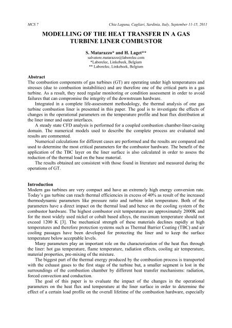
MCS 7 Chia Laguna, Cagliari, Sard<strong>in</strong>ia, Italy, September 11-15, 2011<br />
MODELLING OF THE HEAT TRANSFER IN A GAS<br />
TURBINE LINER COMBUSTOR<br />
S. Matarazzo* and H. Laget**<br />
salvatore.matarazzo@laborelec.com<br />
*Laborelec, L<strong>in</strong>kebeek, Belgium<br />
** Laborelec, L<strong>in</strong>kebeek, Belgium<br />
Abstract<br />
The combustion components <strong>of</strong> <strong>gas</strong> turb<strong>in</strong>es (GT) are operat<strong>in</strong>g under high temperatures and<br />
stresses (due to combustion <strong>in</strong>stabilities) and are <strong>the</strong>refore one <strong>of</strong> <strong>the</strong> critical parts <strong>in</strong> a <strong>gas</strong><br />
turb<strong>in</strong>e. As a result, <strong>the</strong>y need regular monitor<strong>in</strong>g or condition assessment <strong>in</strong> order to avoid<br />
failures that can compromise <strong>the</strong> <strong>in</strong>tegrity <strong>of</strong> <strong>the</strong> downstream hardware.<br />
Integrated <strong>in</strong> a complete life-assessment methodology, <strong>the</strong> <strong>the</strong>rmal analysis <strong>of</strong> one <strong>gas</strong><br />
turb<strong>in</strong>e combustion l<strong>in</strong>er is presented <strong>in</strong> this paper. The goal is to <strong>in</strong>vestigate <strong>the</strong> effects <strong>of</strong><br />
changes <strong>in</strong> <strong>the</strong> operational parameters on <strong>the</strong> temperature pr<strong>of</strong>ile and <strong>heat</strong> flux distribution at<br />
<strong>the</strong> l<strong>in</strong>er <strong>in</strong>ner and outer <strong>in</strong>terfaces.<br />
A steady state CFD analysis is performed for a coupled combustion chamber-l<strong>in</strong>er-cas<strong>in</strong>g<br />
doma<strong>in</strong>. The numerical models used to describe <strong>the</strong> complete process are evaluated and<br />
results are commented.<br />
Numerical calculations for different cases are performed and <strong>the</strong> results are compared and<br />
used to determ<strong>in</strong>e <strong>the</strong> most critical parameters for <strong>the</strong> <strong>combustor</strong> hardware. The benefit <strong>of</strong> <strong>the</strong><br />
application <strong>of</strong> <strong>the</strong> TBC layer on <strong>the</strong> l<strong>in</strong>er surface is also calculated <strong>in</strong> order to assess <strong>the</strong><br />
reduction <strong>of</strong> <strong>the</strong> <strong>the</strong>rmal load on <strong>the</strong> base material.<br />
The results obta<strong>in</strong>ed are consistent with those found <strong>in</strong> literature and measured dur<strong>in</strong>g <strong>the</strong><br />
operations <strong>of</strong> GT.<br />
Introduction<br />
Modern <strong>gas</strong> turb<strong>in</strong>es are very compact and have an extremely high energy conversion rate.<br />
Today’s <strong>gas</strong> turb<strong>in</strong>e can reach <strong>the</strong>rmal efficiencies <strong>in</strong> excess <strong>of</strong> 40% as result <strong>of</strong> <strong>the</strong> <strong>in</strong>creased<br />
<strong>the</strong>rmodynamic parameters like pressure ratio and turb<strong>in</strong>e <strong>in</strong>let temperature. Both <strong>of</strong> <strong>the</strong><br />
parameters have a direct impact on <strong>the</strong> <strong>the</strong>rmal load and hence on <strong>the</strong> cool<strong>in</strong>g system <strong>of</strong> <strong>the</strong><br />
<strong>combustor</strong> hardware. The highest <strong>combustor</strong> exit temperatures are approximately 2000K and<br />
for <strong>the</strong> most widely used nickel or cobalt based alloys, <strong>the</strong> maximum temperature should not<br />
exceed 1200 K [3]. The mechanical strength <strong>of</strong> <strong>the</strong>se materials decl<strong>in</strong>es rapidly at high<br />
temperatures and <strong>the</strong>refore protection systems such as Thermal Barrier Coat<strong>in</strong>g (TBC) and air<br />
cool<strong>in</strong>g passages have been developed for protect<strong>in</strong>g <strong>the</strong> l<strong>in</strong>er and to keep <strong>the</strong> surface<br />
temperature below acceptable levels.<br />
Many parameters play an important role on <strong>the</strong> characterization <strong>of</strong> <strong>the</strong> <strong>heat</strong> flux through<br />
<strong>the</strong> l<strong>in</strong>er: hot <strong>gas</strong> temperature, flame temperature, radiation effects, cool<strong>in</strong>g air temperature,<br />
material properties, pre-mix<strong>in</strong>g <strong>of</strong> <strong>the</strong> mixture.<br />
The biggest part <strong>of</strong> <strong>the</strong> <strong>the</strong>rmal energy produced by <strong>the</strong> combustion process is transported<br />
with <strong>the</strong> exhaust <strong>gas</strong>es to <strong>the</strong> first stage <strong>of</strong> <strong>the</strong> turb<strong>in</strong>e but, a smaller segment is lost <strong>in</strong> <strong>the</strong><br />
surround<strong>in</strong>gs <strong>of</strong> <strong>the</strong> combustion chamber by different <strong>heat</strong> <strong>transfer</strong> mechanisms: radiation,<br />
forced convection and conduction.<br />
The goal <strong>of</strong> this paper is to evaluate <strong>the</strong> impact <strong>of</strong> <strong>the</strong> changes <strong>in</strong> <strong>the</strong> operational<br />
parameters on <strong>the</strong> <strong>heat</strong> flux and temperature at <strong>the</strong> l<strong>in</strong>er surface <strong>in</strong> order to determ<strong>in</strong>e <strong>the</strong><br />
effect <strong>of</strong> a certa<strong>in</strong> load pr<strong>of</strong>ile on <strong>the</strong> overall lifetime <strong>of</strong> <strong>the</strong> combustion hardware, especially
<strong>the</strong> combustion l<strong>in</strong>er. Large amounts <strong>of</strong> data <strong>of</strong> operat<strong>in</strong>g eng<strong>in</strong>es are available to <strong>the</strong> end user<br />
as well as operational experience with heavy duty <strong>gas</strong> turb<strong>in</strong>es; <strong>the</strong> geometry and <strong>the</strong><br />
operational parameters used to def<strong>in</strong>e <strong>the</strong> Inlet Boundary Conditions (IBC) for <strong>the</strong> calculation<br />
are <strong>the</strong>refore related to commercial eng<strong>in</strong>es and data acquired from <strong>the</strong> field.<br />
Integrated fluid structural analysis<br />
The work described <strong>in</strong> this article is part <strong>of</strong> an <strong>in</strong>tegrated fluid-structural method for assess<strong>in</strong>g<br />
<strong>the</strong> evolution <strong>of</strong> <strong>the</strong> condition (and damage) <strong>in</strong> a GT <strong>combustor</strong>.<br />
Figure 1 describes <strong>the</strong> methodology flow used for <strong>the</strong> study.<br />
The variation <strong>of</strong> GT control parameters for a fixed operational <strong>in</strong>terval Δt are measured<br />
and stored by <strong>the</strong> Data Control System (DCS). For <strong>the</strong> most characteristic operat<strong>in</strong>g po<strong>in</strong>ts a<br />
numerical <strong>the</strong>rmal analysis is performed and pressure oscillation measurements are collected<br />
at <strong>the</strong> same time. Both <strong>the</strong>rmal (temperature field) and dynamic (combustion <strong>in</strong>stabilities)<br />
loads are given as <strong>in</strong>put for <strong>the</strong> structural analysis where <strong>the</strong> characteristic stresses and stra<strong>in</strong>s<br />
for <strong>the</strong> considered cases are calculated. F<strong>in</strong>ally, an <strong>in</strong>terpolation <strong>of</strong> <strong>the</strong> stress calculated, on <strong>the</strong><br />
base <strong>of</strong> <strong>the</strong> operational <strong>in</strong>terval, results <strong>in</strong>to a time-dependent stress curve that allows to<br />
estimate <strong>the</strong> cumulated damage on <strong>the</strong> structure.<br />
The transitory behaviour <strong>of</strong> <strong>the</strong> GT Combustor is approximated by a number <strong>of</strong> steady<br />
state calculations. The values <strong>of</strong> <strong>the</strong> <strong>the</strong>rmal loads on <strong>the</strong> chamber l<strong>in</strong>er at <strong>in</strong>termediate<br />
operat<strong>in</strong>g conditions are <strong>in</strong>terpolated between <strong>the</strong> values obta<strong>in</strong>ed for <strong>the</strong> calculated<br />
conditions avoid<strong>in</strong>g extremely long transient CFD calculations. The advantage <strong>of</strong> <strong>the</strong> method<br />
is <strong>the</strong> limited computational effort needed for <strong>the</strong> numerical calculation as compared to a full<br />
transient simulation <strong>of</strong> <strong>the</strong> operation pr<strong>of</strong>ile.<br />
Figure 1. Methodology flow chart; <strong>the</strong> red box highlights <strong>the</strong> work described <strong>in</strong> <strong>the</strong> article.<br />
Geometry<br />
Figure 2 shows <strong>the</strong> geometry <strong>of</strong> <strong>the</strong> combustion system used for <strong>the</strong> calculation. It is a<br />
cannular <strong>combustor</strong> equipped with five premix burners with air swirlers and <strong>gas</strong> <strong>in</strong>jectors.<br />
Thanks to <strong>the</strong> sp<strong>in</strong> given by <strong>the</strong> air swirlers, <strong>the</strong> premixed mixture recirculates <strong>in</strong>to <strong>the</strong><br />
chamber <strong>in</strong>creas<strong>in</strong>g <strong>the</strong> residence time and complet<strong>in</strong>g <strong>the</strong> combustion process (reduc<strong>in</strong>g CO<br />
formation).
The l<strong>in</strong>er is cooled at <strong>the</strong> outer side by <strong>the</strong> compressor discharge air which, before<br />
enter<strong>in</strong>g <strong>the</strong> combustion chamber, circulates counterflow externally with <strong>the</strong> tw<strong>of</strong>old effect <strong>of</strong><br />
cool<strong>in</strong>g <strong>the</strong> l<strong>in</strong>er walls and be<strong>in</strong>g pre-<strong>heat</strong>ed (to <strong>in</strong>crease <strong>the</strong> combustion efficiency).<br />
Four different fuel l<strong>in</strong>es feed <strong>the</strong> chamber with natural <strong>gas</strong>: <strong>the</strong> primary l<strong>in</strong>e br<strong>in</strong>gs <strong>the</strong><br />
fuel at <strong>the</strong> tip <strong>of</strong> <strong>the</strong> nozzle and acts on <strong>the</strong> pilot flame, <strong>the</strong> quaternary l<strong>in</strong>e delivers a<br />
percentage <strong>of</strong> <strong>the</strong> total feed <strong>gas</strong> to <strong>the</strong> air <strong>in</strong>let upstream <strong>the</strong> premix swirlers; secondary and<br />
tertiary l<strong>in</strong>es br<strong>in</strong>g <strong>the</strong> fuel to, respectively, 4 and 1 burners with premix <strong>gas</strong> <strong>in</strong>jectors. The<br />
open<strong>in</strong>g <strong>of</strong> <strong>the</strong> split valve changes accord<strong>in</strong>g to <strong>the</strong> power output and <strong>the</strong> start-up or turndown<br />
procedure.<br />
The asymmetry <strong>in</strong> <strong>the</strong> temperature field generates different temperature gradients across<br />
<strong>the</strong> wall and different <strong>heat</strong> flux for <strong>the</strong> structure. These effects are <strong>in</strong>vestigated <strong>in</strong> more detail<br />
and <strong>the</strong> possible damage on <strong>the</strong> structure are presented <strong>in</strong> <strong>the</strong> follow<strong>in</strong>g sections.<br />
Figure 2. (a) CAD draw<strong>in</strong>gs and Air Flow for <strong>the</strong> cannular combustion system;<br />
(b) element grid for <strong>the</strong> three doma<strong>in</strong>s.<br />
Thermal Analysis <strong>of</strong> <strong>the</strong> l<strong>in</strong>er wall<br />
Dur<strong>in</strong>g <strong>the</strong> combustion process, <strong>heat</strong> is <strong>transfer</strong>red from <strong>the</strong> hot flame by radiation and by<br />
convection <strong>of</strong> <strong>the</strong> combustion <strong>gas</strong>es. The radiative <strong>heat</strong> exchange depends on <strong>the</strong> distance<br />
between <strong>the</strong> flame and <strong>the</strong> walls and by <strong>the</strong> absorption <strong>of</strong> <strong>the</strong> colder combustion <strong>gas</strong>es <strong>in</strong><br />
between. In <strong>the</strong> modern GT <strong>the</strong> contribution <strong>of</strong> <strong>the</strong> radiative <strong>heat</strong> is lower because <strong>of</strong> <strong>the</strong> high<br />
bulk flow velocity and short residence times but it can have a significant impact on <strong>the</strong><br />
chemical reactions and thus on <strong>the</strong> NO x formation [3].<br />
Figure 3 shows <strong>the</strong> <strong>heat</strong> flux through <strong>the</strong> l<strong>in</strong>er: it is <strong>heat</strong>ed by convection and radiation<br />
from <strong>the</strong> exhaust <strong>gas</strong> <strong>in</strong>side and it is cooled by radiation to <strong>the</strong> outer cas<strong>in</strong>g and by convection<br />
to <strong>the</strong> cas<strong>in</strong>g air passage.<br />
cas<br />
Q<br />
conv<br />
cas<br />
Q<br />
rad<br />
ch<br />
Q<br />
conv<br />
ch<br />
Q<br />
cond<br />
ch<br />
Q<br />
rad<br />
Figure 3. Heat fluxes through <strong>the</strong> l<strong>in</strong>er walls.
Under steady-state condition, <strong>the</strong> <strong>heat</strong> <strong>transfer</strong> <strong>in</strong>to <strong>the</strong> wall doma<strong>in</strong> is balanced by <strong>the</strong><br />
<strong>heat</strong> <strong>transfer</strong> out <strong>of</strong> it.<br />
Q + Q + Q = Q + Q<br />
( 1)<br />
ch<br />
conv<br />
ch<br />
rad<br />
w<br />
cond<br />
cas<br />
conv<br />
cas<br />
rad<br />
For flame temperatures up to about 1700 K, forced convection is <strong>the</strong> dom<strong>in</strong>ant mechanism<br />
<strong>in</strong> flame <strong>heat</strong> <strong>transfer</strong> [8]. Loss <strong>of</strong> <strong>heat</strong> by conduction along <strong>the</strong> l<strong>in</strong>er wall is very small<br />
compared to <strong>the</strong> o<strong>the</strong>r terms. The convective, radiative and conductive <strong>heat</strong> are calculated<br />
us<strong>in</strong>g <strong>the</strong> equations sotto:<br />
where,<br />
T T<br />
<strong>gas</strong> ,<br />
wall<br />
and<br />
Tmax<br />
Q<br />
Q<br />
rad<br />
Q<br />
conv<br />
1−2<br />
cond<br />
= h T<br />
= σ ε<br />
SB<br />
k<br />
=<br />
t<br />
(<br />
<strong>gas</strong><br />
− Twall<br />
)<br />
4 4<br />
( T −T<br />
)<br />
w<br />
w<br />
max<br />
wall<br />
( T − T )<br />
w1<br />
w2<br />
[K]are respectively, <strong>the</strong> temperature <strong>of</strong> <strong>the</strong> exhaust <strong>gas</strong> near <strong>the</strong> wall (wall<br />
adjacent temperature), at <strong>the</strong> l<strong>in</strong>er wall and <strong>the</strong> maximum flame temperature,<br />
h [W/m² K] is <strong>the</strong> <strong>heat</strong> <strong>transfer</strong> coefficient;<br />
ε is <strong>the</strong> emissivity <strong>of</strong> <strong>the</strong> wall;<br />
k<br />
w<br />
[W/m K] is <strong>the</strong> <strong>the</strong>rmal conductivity <strong>of</strong> <strong>the</strong> l<strong>in</strong>er wall (for <strong>the</strong> base material and TBC);<br />
t [m] is <strong>the</strong> thickness <strong>of</strong> <strong>the</strong> l<strong>in</strong>er wall;<br />
w<br />
σ [W/m² K 4 ] is <strong>the</strong> Stefan-Boltzman constant.<br />
SB<br />
Flame temperature, absorption, reflection and emission characteristics <strong>of</strong> <strong>the</strong> l<strong>in</strong>er<br />
material, equivalence ratio <strong>of</strong> <strong>the</strong> mixture and wall thickness directly <strong>in</strong>fluence <strong>the</strong> <strong>heat</strong> flux<br />
while flue <strong>gas</strong> composition, mass flow velocity and cool<strong>in</strong>g techniques have an <strong>in</strong>direct effect.<br />
Some <strong>of</strong> <strong>the</strong>m are <strong>the</strong>refore used to assess <strong>the</strong> impact <strong>of</strong> <strong>the</strong>ir changes on <strong>the</strong> <strong>heat</strong> flux by <strong>the</strong><br />
<strong>heat</strong> <strong>transfer</strong> coefficient. The <strong>heat</strong> <strong>transfer</strong> coefficient h is <strong>the</strong> amount <strong>of</strong> <strong>heat</strong> energy cross<strong>in</strong>g<br />
a unit area per unit time per unit temperature.<br />
The results are presented <strong>in</strong> <strong>the</strong> follow<strong>in</strong>g paragraphs.<br />
Computational Setup<br />
Start<strong>in</strong>g from an unique geometry file, three separate doma<strong>in</strong>s has been modelled and meshed<br />
us<strong>in</strong>g Ansys 12.1 Workbench: <strong>the</strong> fluid cas<strong>in</strong>g cavity walls, <strong>the</strong> solid l<strong>in</strong>er and <strong>the</strong> fluid<br />
chamber doma<strong>in</strong> (Figure 2,a).<br />
The element grid has been prepared us<strong>in</strong>g unstructured tetrahedrons with an average<br />
skewness value <strong>of</strong> 0.28 (Figure 2, b). The siz<strong>in</strong>g parameters are listed <strong>in</strong> <strong>the</strong> Table 1.<br />
Table 1. Mesh size and elements characteristic dimensions for <strong>the</strong> three doma<strong>in</strong>s.<br />
Chamber Fluid<br />
Doma<strong>in</strong><br />
Cas<strong>in</strong>g Fluid<br />
Doma<strong>in</strong><br />
L<strong>in</strong>er Solid<br />
Doma<strong>in</strong><br />
m<strong>in</strong> edge length [mm] 2 3 2<br />
max edge length [mm] 5 6 2<br />
Elements 8.6M 3.8M 1.6M<br />
( 2)<br />
( 3)<br />
( 4)
The fluid-dynamic analysis was carried out us<strong>in</strong>g <strong>the</strong> commercial code ANSYS CFX v12.1.<br />
For both <strong>of</strong> <strong>the</strong> fluid doma<strong>in</strong>s, <strong>the</strong> flow is turbulent. The standard k-ε turbulence model<br />
was chosen to predict <strong>the</strong> effect <strong>of</strong> <strong>the</strong> turbulence on <strong>the</strong> flow, on <strong>the</strong> <strong>heat</strong> <strong>transfer</strong> and on <strong>the</strong><br />
combustion process itself. Because <strong>the</strong> value <strong>of</strong> Mach number is lower than 0.3 <strong>in</strong> <strong>the</strong> whole<br />
doma<strong>in</strong>, <strong>the</strong> viscous effects can be neglected and <strong>the</strong> <strong>the</strong>rmal energy <strong>heat</strong> <strong>transfer</strong> model is<br />
<strong>the</strong>refore used.<br />
The comb<strong>in</strong>ed eddy dissipation-f<strong>in</strong>ite rate chemistry model (EDM/FRC) is chosen to<br />
model <strong>the</strong> combustion reaction process. It uses a s<strong>in</strong>gle-step reaction model and it describes<br />
<strong>the</strong> evolution <strong>of</strong> <strong>the</strong> combustion process through <strong>the</strong> calculation <strong>of</strong> <strong>the</strong> reaction rate. O<strong>the</strong>r<br />
combustion models have been tested but EDM/FRC is <strong>the</strong> best option because <strong>of</strong> its capability<br />
<strong>of</strong> cover<strong>in</strong>g <strong>the</strong> whole range <strong>of</strong> Damkholer numbers, for both “turbulent mix<strong>in</strong>g-dom<strong>in</strong>ated"<br />
and “chemistry-dom<strong>in</strong>ated” reaction rates.<br />
Fuel composition has a big impact on <strong>the</strong> combustion reaction process. Natural <strong>gas</strong> is<br />
composed primarily <strong>of</strong> methane (CH 4 ) and between 0-20% <strong>of</strong> higher hydrocarbons. Lam<strong>in</strong>ar<br />
and turbulent burn<strong>in</strong>g velocities <strong>of</strong> <strong>the</strong> flame vary for different compositions caus<strong>in</strong>g an<br />
unstable behaviour <strong>of</strong> <strong>the</strong> flame. For this analysis, pure methane is used as fuel and a mixture<br />
O 2 -N 2 as oxidizer (0.232-0.768 mass fractions).<br />
The radiative effects on <strong>the</strong> <strong>heat</strong> <strong>transfer</strong> are modelled us<strong>in</strong>g <strong>the</strong> P1 <strong>the</strong>rmal radiation<br />
model.<br />
Chamber Doma<strong>in</strong><br />
The complete burner geometry has been <strong>in</strong>cluded <strong>in</strong> <strong>the</strong> chamber fluid doma<strong>in</strong> to observe<br />
<strong>the</strong> effects <strong>of</strong> <strong>the</strong> fluid paths. The sp<strong>in</strong> given by <strong>the</strong> burner swirl<strong>in</strong>g vanes and <strong>the</strong> <strong>gas</strong> <strong>in</strong>jector<br />
location play an important role on <strong>the</strong> dynamics <strong>of</strong> <strong>the</strong> flame and its stabilization. The rate <strong>of</strong><br />
mix<strong>in</strong>g achieved affects <strong>the</strong> flame temperature, <strong>the</strong> recirculation zone (very important for <strong>the</strong><br />
flame stabilization), <strong>the</strong> <strong>heat</strong> release and <strong>the</strong> maximum wall temperature.<br />
Three different <strong>in</strong>lets have been def<strong>in</strong>ed: <strong>the</strong> air + quaternary fuel, <strong>the</strong> secondary <strong>gas</strong> <strong>in</strong>let<br />
and <strong>the</strong> tertiary <strong>gas</strong> <strong>in</strong>let. Measured mass flows and <strong>the</strong> species compositions (CH 4 , O 2 and N 2<br />
mass fractions) at <strong>the</strong> three different <strong>in</strong>lets for different open<strong>in</strong>gs <strong>of</strong> <strong>the</strong> fuel split l<strong>in</strong>e have<br />
been assigned as Inlet Boundary Condition (IBC) for <strong>the</strong> fluid doma<strong>in</strong>s.<br />
L<strong>in</strong>er Solid Doma<strong>in</strong><br />
Ansys CFX enables to create, through <strong>the</strong> conjugate <strong>heat</strong> <strong>transfer</strong> model, solid regions <strong>in</strong><br />
which <strong>the</strong> equations for <strong>heat</strong> <strong>transfer</strong> are solved, but with no flow. With<strong>in</strong> <strong>the</strong> solid doma<strong>in</strong>s,<br />
<strong>the</strong> conservation <strong>of</strong> energy equation can account for <strong>heat</strong> transport due to solid motion,<br />
conduction, and volumetric <strong>heat</strong> sources:<br />
( 5)<br />
where h, ρ, and λ are <strong>the</strong> enthalpy, density, and <strong>the</strong>rmal conductivity <strong>of</strong> <strong>the</strong> solid,<br />
respectively. U s is <strong>the</strong> solid velocity, if specified, and S E is an optional volumetric <strong>heat</strong> source.<br />
The solid motion advection term (<strong>the</strong> term <strong>in</strong>clud<strong>in</strong>g U s ) is also optional and is added only<br />
when a solid motion velocity is set. In <strong>the</strong> case considered, no solid velocity is set and <strong>the</strong><br />
term is <strong>the</strong>refore neglected.<br />
Nickel based alloys are generally used for combustion l<strong>in</strong>ers because <strong>of</strong> <strong>the</strong>ir high<br />
resistance to oxidation and corrosion and high temperature strength. The base material is<br />
<strong>in</strong>ternally covered by a th<strong>in</strong> layer <strong>of</strong> TBC (≈500 µm) which aims to reduce <strong>the</strong> metal surface<br />
temperature and protects <strong>the</strong> base material.
Figure 4. Composition <strong>of</strong> TBC Layers and typical temperature drop through <strong>the</strong> whole l<strong>in</strong>er.<br />
The TBC material is characterized by very low emissivity and low <strong>the</strong>rmal conductivity.<br />
It is divided <strong>in</strong>to two different layers: NiCrAlY bound coat<strong>in</strong>g (at <strong>the</strong> base material <strong>in</strong>terface)<br />
and <strong>the</strong> ceramic layer composed by yttria-stabilized ZrO 2 which provide <strong>the</strong> highest resistance<br />
to <strong>the</strong> <strong>heat</strong> flux from <strong>the</strong> chamber wall to <strong>the</strong> GT cas<strong>in</strong>g (Figure 4).<br />
The reduction <strong>of</strong> temperature at <strong>the</strong> <strong>in</strong>terface with <strong>the</strong> base material achievable with this<br />
technique is about 100 °C. 1<br />
The material properties adopted for <strong>the</strong> calculation are listed <strong>in</strong> <strong>the</strong> Table 2.<br />
Table 2. Material properties <strong>of</strong> <strong>the</strong> l<strong>in</strong>er base material for <strong>the</strong> solid doma<strong>in</strong>. Source: Haynes<br />
International, Inc.<br />
Values *<br />
Molar Mass [kg/kmol] 60.25<br />
Density [kg/m³] 8220<br />
Specific <strong>heat</strong> capacity [J/(kg K)] 486<br />
Thermal conductivity [W/(m K)] 9.1<br />
* reference state: 25°C<br />
Cas<strong>in</strong>g Cavity Fluid Doma<strong>in</strong><br />
To account for <strong>the</strong> cool<strong>in</strong>g effects <strong>of</strong> <strong>the</strong> compressor discharge air pass<strong>in</strong>g counterflow on<br />
<strong>the</strong> l<strong>in</strong>er outer surface, <strong>the</strong> Cas<strong>in</strong>g Cavity fluid doma<strong>in</strong> has been created. The mass flow and<br />
temperature <strong>of</strong> <strong>the</strong> fluid at <strong>the</strong> cas<strong>in</strong>g cavity <strong>in</strong>let are obta<strong>in</strong>ed from <strong>the</strong> DCS system. The<br />
presence <strong>of</strong> a number <strong>of</strong> ribs on <strong>the</strong> outer side <strong>of</strong> <strong>the</strong> l<strong>in</strong>er reduces <strong>the</strong> velocity field <strong>of</strong> <strong>the</strong> air,<br />
<strong>in</strong>crease <strong>the</strong> residence time and enhance <strong>the</strong> <strong>heat</strong> <strong>transfer</strong> improv<strong>in</strong>g <strong>the</strong> cool<strong>in</strong>g effect on <strong>the</strong><br />
l<strong>in</strong>er wall (forced convection). The mesh at <strong>the</strong> l<strong>in</strong>er-cas<strong>in</strong>g <strong>in</strong>terface has been ref<strong>in</strong>ed <strong>in</strong> order<br />
to capture <strong>the</strong>se effects. The calculated temperature at <strong>the</strong> outlet <strong>of</strong> <strong>the</strong> cas<strong>in</strong>g doma<strong>in</strong> (pre<strong>heat</strong>ed<br />
air) is used as <strong>in</strong>put value for <strong>the</strong> air IBC at <strong>the</strong> chamber doma<strong>in</strong>.<br />
Selection <strong>of</strong> <strong>the</strong> Operation Po<strong>in</strong>ts (OP)<br />
Gas turb<strong>in</strong>es are very flexible <strong>in</strong> operation, and depend<strong>in</strong>g upon market and grid conditions,<br />
<strong>the</strong>ir load sett<strong>in</strong>gs can vary over <strong>the</strong> day, rang<strong>in</strong>g between m<strong>in</strong>imum load and base load<br />
1 Data on TBC materials and reduction <strong>of</strong> temperatures achieved at <strong>the</strong> BM-TBC <strong>in</strong>terface has been estimated<br />
based on o<strong>the</strong>r model<strong>in</strong>g studies at <strong>the</strong> Structural Integrity Assessment and Monitor<strong>in</strong>g (SIAM) department <strong>of</strong><br />
Laborelec.
operation. Moreover, frequent start/stop operation <strong>of</strong> <strong>gas</strong> turb<strong>in</strong>es is also widespread <strong>in</strong> order<br />
to deliver peak power. Six cases are selected <strong>in</strong> order to assess <strong>the</strong> weight <strong>of</strong> <strong>the</strong> changes <strong>in</strong><br />
<strong>the</strong> operation variables on <strong>the</strong> <strong>the</strong>rmal loads.<br />
Table 3. Characteristic OP selected.<br />
OP 1 OP2 OP3 OP4 OP5 OP6<br />
Power [MW] 243 177 117 243 243 243<br />
Air Flow [kg/s] 30.9 21.43 20.05 24.7 30.9 30.9<br />
Gas Mass Flow [kg/s] 0.72 0.5 0.47 0.72 0.72 0.72<br />
Quaternary Fuel [%] 11 11 11 11 0 11<br />
Tertiary/Secondary Fuel Split [%] 81.7 82.73 83.4 81.7 81.7 81.7<br />
Compressor Air discharge Temp. [°C] 373 337 331 373 373 373<br />
Compressor Air Discharge Press. [bar] 14.95 10.3 9.5 14.95 14.95 14.95<br />
Equivalence ratio Φ 0.4 0.4 0.4 0.5 0.4 0.4<br />
L<strong>in</strong>er material BM BM BM BM BM BM+TBC<br />
The power output <strong>of</strong> <strong>the</strong> GT <strong>in</strong>fluences <strong>the</strong> flame temperature and <strong>the</strong> mass flow velocity.<br />
The fuel split modifies <strong>the</strong> temperature distribution <strong>in</strong>side <strong>the</strong> chamber generat<strong>in</strong>g non<br />
uniform gradients <strong>of</strong> temperatures at <strong>the</strong> l<strong>in</strong>er surface.<br />
OP1, OP2 and OP3 compare <strong>the</strong> behaviour at base load, <strong>in</strong>termediate and m<strong>in</strong>imum load<br />
for premix steady state operation.<br />
OP4 shows <strong>the</strong> dependency <strong>of</strong> changes <strong>in</strong> <strong>the</strong> Equivalence ratio Φ and <strong>the</strong>ir impact on <strong>the</strong><br />
flame temperature [9].<br />
OP5 is <strong>the</strong> scenario where <strong>the</strong> quaternary valve is closed. The quaternary l<strong>in</strong>e <strong>of</strong> <strong>the</strong> fuel<br />
system l<strong>in</strong>e delivers part <strong>of</strong> <strong>the</strong> total <strong>gas</strong> mass flow at <strong>the</strong> air <strong>in</strong>let where a prelim<strong>in</strong>ary<br />
premix<strong>in</strong>g is achieved. It helps to stabilize <strong>the</strong> flame and uniforms <strong>the</strong> <strong>gas</strong> mixture fraction.<br />
Last case OP6, models <strong>the</strong> effect <strong>of</strong> <strong>the</strong> application <strong>of</strong> a 500 µm TBC layer on <strong>the</strong> <strong>in</strong>ner<br />
surface <strong>of</strong> <strong>the</strong> l<strong>in</strong>er wall. The calculation doma<strong>in</strong> is composed by l<strong>in</strong>er solid doma<strong>in</strong> and<br />
cas<strong>in</strong>g cavity fluid doma<strong>in</strong>. The boundary condition at <strong>the</strong> <strong>in</strong>ner side <strong>of</strong> <strong>the</strong> l<strong>in</strong>er is <strong>the</strong><br />
temperature field exported from case OP1 reduced by 100 K <strong>in</strong> order to model <strong>the</strong> effect <strong>of</strong><br />
<strong>the</strong> temperature reduction at <strong>the</strong> base material <strong>in</strong>terface obta<strong>in</strong>ed. The goal is to look at <strong>the</strong><br />
temperature pr<strong>of</strong>iles at <strong>the</strong> <strong>in</strong>ner and outer surface <strong>of</strong> <strong>the</strong> l<strong>in</strong>er.<br />
The parameters describ<strong>in</strong>g <strong>the</strong> selected cases are listed <strong>in</strong> Table 3.<br />
Results<br />
The results <strong>of</strong> <strong>the</strong> <strong>the</strong>rmal analysis performed for <strong>the</strong> six cases are presented <strong>in</strong> this section.<br />
The temperature pr<strong>of</strong>ile are shown <strong>in</strong> Figure 5 while Table 4 and Figure 7 compare some <strong>of</strong><br />
<strong>the</strong> calculated parameters.<br />
The steady-state results <strong>of</strong> <strong>the</strong> model show <strong>the</strong> different distribution <strong>of</strong> temperature along<br />
<strong>the</strong> l<strong>in</strong>er cross section plane pass<strong>in</strong>g through two <strong>of</strong> <strong>the</strong> burners mid-l<strong>in</strong>es, one belong<strong>in</strong>g to<br />
<strong>the</strong> four secondary burners and <strong>the</strong> o<strong>the</strong>r one belong<strong>in</strong>g to <strong>the</strong> tertiary l<strong>in</strong>e. Differences <strong>in</strong> <strong>the</strong><br />
temperature are calculated because <strong>of</strong> <strong>the</strong> reduced fuel concentration for <strong>the</strong> tertiary l<strong>in</strong>e.<br />
The hot regions <strong>of</strong> <strong>the</strong> chamber are highlighted <strong>in</strong> <strong>the</strong> Figure 5. They are located at <strong>the</strong><br />
recirculation zone over <strong>the</strong> top <strong>of</strong> <strong>the</strong> burner and at <strong>the</strong> outlet <strong>of</strong> <strong>the</strong> <strong>combustor</strong> l<strong>in</strong>er where <strong>the</strong><br />
temperature tend to be uniform.<br />
The average value <strong>of</strong> temperature calculated at <strong>the</strong> outlet <strong>of</strong> <strong>the</strong> chamber is compared with<br />
<strong>the</strong> corrected exhaust temperature estimated by <strong>the</strong> DCS system at <strong>the</strong> first stage <strong>of</strong> <strong>the</strong><br />
turb<strong>in</strong>e nozzles (Figure 6). We observe a very good consistency between <strong>the</strong> temperature
calculated by <strong>the</strong> CFD model and <strong>the</strong> estimated values from <strong>the</strong> DCS system at high and base<br />
loads (relative error ≈1.5%) and a small deviation at partial load (relative error 2.7%).<br />
The turbulence <strong>in</strong> <strong>the</strong> flow generated by <strong>the</strong> swirlers affects <strong>the</strong> temperature distribution <strong>in</strong><br />
<strong>the</strong> <strong>in</strong>ner region <strong>of</strong> <strong>the</strong> chamber [10]. Wider cold regions are present at lower loads and <strong>the</strong><br />
temperatures are less uniform <strong>the</strong>n at base load.<br />
Figure 5. Temperature pr<strong>of</strong>ile for <strong>the</strong> different operat<strong>in</strong>g po<strong>in</strong>ts: OP1, OP2, OP3, OP4. The<br />
hot regions (T> 0.95*T MAX ) are highlighted with black l<strong>in</strong>es. The location <strong>of</strong> <strong>the</strong> zoomw<strong>in</strong>dow<br />
from Figure 8 is <strong>in</strong>dicated.<br />
Figure 6. Comparison between <strong>the</strong> CFD calculated average temperatures at <strong>the</strong> chamber<br />
outlet with <strong>the</strong> estimated values from <strong>the</strong> DCS system.<br />
Look<strong>in</strong>g at <strong>the</strong> CH 4 mass fraction, <strong>the</strong> values for <strong>the</strong> average concentration calculated <strong>in</strong> a<br />
plane located at 1/8 <strong>of</strong> <strong>the</strong> <strong>combustor</strong> total length, show that <strong>the</strong> mixture is consumed faster at<br />
higher loads. Higher loads generates <strong>in</strong> fact higher flow velocity, <strong>the</strong> turbulence k<strong>in</strong>etic<br />
energy <strong>in</strong>crease enhanc<strong>in</strong>g <strong>the</strong> mix between <strong>the</strong> <strong>gas</strong> and <strong>the</strong> air which benefit <strong>the</strong> combustion<br />
process itself.
Table 4. Calculated parameter for <strong>the</strong> cases selected.<br />
OP 1 OP2 OP3 OP4 OP5 OP6<br />
T max @Chamber [K] 1604 1568 1570 2011 1597 1604<br />
T ave @Chamber [K] 1300 1208 1189 1640 1291 1300<br />
T ave @Chamber Outlet [K] 1566 1525 1512 1955 1561 1566<br />
Estimated T@Turb<strong>in</strong>e Inlet [K] 1543.95 1509.35 1471.11 - - 1543.95<br />
*<br />
T max L<strong>in</strong>er <strong>in</strong>ner surface [K] 1398 1318 1293 1676 1393 1298**<br />
T ave L<strong>in</strong>er <strong>in</strong>ner surface [K] 1116 955 920.4 1406 983.1 925.2<br />
ΔT L<strong>in</strong>er [K] 215.4 147.1 120.2 302.6 206.8 170.6<br />
Heat <strong>transfer</strong> coefficient 2047.42 1808,25 1473,68 1333,24 2080,78 -<br />
[W/m²K]<br />
V ave @Chamber [m/s] 80.38 75.91 74.23 78.14 79.57 80.38<br />
Residence time [s] 0.019 0.021 0.021 0.019 0.019 0.019<br />
CH 4 average mass<br />
0.00584 0.00701 0.00727 0.00508 0.00596 0.00584<br />
fraction@h_section_plane<br />
ΔT between cas<strong>in</strong>g cavity outlet 30.22 24.94 25.38 49.48 28.94 23.20<br />
and <strong>in</strong>let [K]<br />
* estimated values from DCS<br />
**values at <strong>the</strong> base material-TBC <strong>in</strong>terface<br />
Figure 7. Comparison charts. Reference case: OP1. Values plotted along <strong>the</strong> axial l<strong>in</strong>e at <strong>the</strong><br />
l<strong>in</strong>er <strong>in</strong>terface. (a) Load variation effects; (b) equivalence ratio variation effects; (c)<br />
quaternary l<strong>in</strong>e closure effects; (d) TBC layer application effects.
The <strong>heat</strong> <strong>transfer</strong> coefficient calculated at <strong>the</strong> l<strong>in</strong>er <strong>in</strong>terface for <strong>the</strong> different cases<br />
highlights <strong>the</strong> importance <strong>of</strong> <strong>the</strong> distribution <strong>of</strong> <strong>the</strong> temperature <strong>in</strong>side <strong>the</strong> chamber. OP1, OP2<br />
and OP3 show a similar and proportional temperature distribution (Figure 7a) and <strong>the</strong>refore<br />
<strong>the</strong> calculated HTC is decreas<strong>in</strong>g proportionally to <strong>the</strong> load output <strong>of</strong> <strong>the</strong> <strong>combustor</strong>. Figure<br />
7b shows <strong>the</strong> effect <strong>of</strong> <strong>the</strong> Φ variation. For a higher value <strong>of</strong> <strong>the</strong> equivalence ratio, <strong>the</strong><br />
difference <strong>in</strong> temperature between <strong>the</strong> solid surface and surround<strong>in</strong>g fluid area <strong>in</strong>creases and<br />
<strong>the</strong>refore, <strong>the</strong> HTC decreases.<br />
The OP5 results show <strong>the</strong> effect <strong>of</strong> <strong>the</strong> elim<strong>in</strong>ation <strong>of</strong> <strong>the</strong> fuel <strong>in</strong> <strong>the</strong> quaternary l<strong>in</strong>e on <strong>the</strong><br />
<strong>the</strong>rmal behaviour <strong>of</strong> <strong>the</strong> <strong>combustor</strong>. The technique is useful for <strong>the</strong> stabilization <strong>of</strong> <strong>the</strong> flame<br />
never<strong>the</strong>less, clos<strong>in</strong>g <strong>the</strong> quaternary valve could be beneficial for <strong>the</strong> l<strong>in</strong>er walls because it<br />
lowers <strong>the</strong> temperatures at <strong>the</strong> l<strong>in</strong>er <strong>in</strong>terface as shown <strong>in</strong> <strong>the</strong> Figure 7(c).<br />
Figure 8 presents a zoom <strong>of</strong> <strong>the</strong> chamber-l<strong>in</strong>er-cas<strong>in</strong>g <strong>in</strong>terface. The temperature gradients<br />
generated by <strong>the</strong> fuel splits and by <strong>the</strong> turbulent flow as well as <strong>the</strong> cool<strong>in</strong>g effect on <strong>the</strong> outer<br />
l<strong>in</strong>er surface are visible. The compressor discharge air pass<strong>in</strong>g through <strong>the</strong> cavity walls cools<br />
<strong>the</strong> l<strong>in</strong>er and <strong>the</strong>refore <strong>the</strong> temperature <strong>of</strong> <strong>the</strong> discharge air <strong>in</strong>creases (see Table 4). Because <strong>of</strong><br />
<strong>the</strong> non-uniformity <strong>of</strong> <strong>the</strong> temperature gradients both <strong>in</strong> <strong>in</strong>tensity and direction, <strong>the</strong> material<br />
reacts with different <strong>the</strong>rmal expansion rates caus<strong>in</strong>g <strong>the</strong> bulg<strong>in</strong>g <strong>of</strong> <strong>the</strong> l<strong>in</strong>er and degradation<br />
<strong>of</strong> <strong>the</strong> material.<br />
Experimental data ga<strong>the</strong>red estimates <strong>the</strong> reduction <strong>of</strong> <strong>the</strong> temperature at <strong>the</strong> BM-TBC<br />
<strong>in</strong>terface. The results obta<strong>in</strong>ed by <strong>the</strong> CFD model <strong>in</strong>dicate a reduction <strong>of</strong> <strong>the</strong> temperature<br />
gradient through <strong>the</strong> l<strong>in</strong>er section to 309.4 K <strong>in</strong>stead <strong>of</strong> <strong>the</strong> 394.9 K calculated for <strong>the</strong> BM<br />
without TBC layer (OP1).<br />
Figure 8. Temperatures gradient zoom at <strong>the</strong> chamber-l<strong>in</strong>er-cas<strong>in</strong>g <strong>in</strong>terfaces.<br />
Conclusion<br />
The energy released by <strong>the</strong> combustion reaction process <strong>in</strong>side <strong>the</strong> combustion chamber is<br />
<strong>transfer</strong>red to <strong>the</strong> surround<strong>in</strong>gs caus<strong>in</strong>g temperature gradients and <strong>heat</strong> flux oscillations <strong>in</strong> <strong>the</strong><br />
l<strong>in</strong>er solid doma<strong>in</strong> that depletes <strong>the</strong> base material and coat<strong>in</strong>g and that damages <strong>the</strong> chamber<br />
walls. Degradation <strong>of</strong> <strong>the</strong> material properties, bulg<strong>in</strong>g <strong>of</strong> <strong>the</strong> chamber, crack development and<br />
release <strong>of</strong> damaged pieces downstream are some <strong>of</strong> <strong>the</strong> most common failures <strong>of</strong> <strong>the</strong><br />
combustion l<strong>in</strong>ers.<br />
Object <strong>of</strong> <strong>the</strong> study is to def<strong>in</strong>e <strong>the</strong> <strong>the</strong>rmo-pressure conditions and <strong>the</strong>ir dependency from<br />
<strong>the</strong> OP at <strong>the</strong> l<strong>in</strong>er wall surfaces (external and <strong>in</strong>ternal) for <strong>the</strong> development <strong>of</strong> an <strong>in</strong>tegrated<br />
fluid-structural model used for life time assessment <strong>of</strong> <strong>the</strong> <strong>combustor</strong> hardware.
The follow<strong>in</strong>g conclusion can be drawn from this work:<br />
• <strong>the</strong> fluid analysis performed on <strong>the</strong> complete combustion hardware shows its<br />
potential <strong>in</strong> <strong>the</strong> identification <strong>of</strong> <strong>the</strong> most dangerous operat<strong>in</strong>g condition for a GT<br />
<strong>combustor</strong> l<strong>in</strong>er; <strong>the</strong> effect <strong>of</strong> certa<strong>in</strong> parameters (operat<strong>in</strong>g conditions, l<strong>in</strong>er<br />
materials, geometries, cool<strong>in</strong>g flow) on <strong>the</strong> l<strong>in</strong>er boundaries has been <strong>in</strong>vestigated;<br />
• <strong>the</strong> models used for <strong>the</strong> simulation <strong>of</strong> <strong>the</strong> process are suitable for <strong>the</strong> purpose<br />
although <strong>the</strong> quality <strong>of</strong> <strong>the</strong> results needs to be fur<strong>the</strong>r evaluated;<br />
• <strong>the</strong> calculated values are consistent with those found <strong>in</strong> literature and measured<br />
dur<strong>in</strong>g <strong>the</strong> operation <strong>of</strong> <strong>the</strong> GT. However, <strong>the</strong> model needs to be validated with<br />
measurement campaigns;<br />
• detailed <strong>in</strong>formation on <strong>the</strong> temperature pr<strong>of</strong>ile and <strong>heat</strong> flux can be obta<strong>in</strong>ed at<br />
<strong>the</strong> l<strong>in</strong>er boundaries but, a more specific structural analysis needs to be<br />
implemented to <strong>in</strong>vestigate <strong>the</strong> effects <strong>of</strong> <strong>the</strong> <strong>the</strong>rmal loads on <strong>the</strong> structure itself;<br />
• a first approach <strong>in</strong> calculat<strong>in</strong>g <strong>the</strong> effect <strong>of</strong> <strong>the</strong> TBC on <strong>the</strong> temperature pr<strong>of</strong>ile at<br />
<strong>the</strong> boundaries <strong>of</strong> <strong>the</strong> l<strong>in</strong>er is feasible with fluid analysis calculations but it is not<br />
enough to <strong>in</strong>vestigate <strong>the</strong> <strong>heat</strong> flux and <strong>the</strong> <strong>the</strong>rmal conditions at <strong>the</strong> base material-<br />
TBC <strong>in</strong>terface unless a separate TBC doma<strong>in</strong> is used for <strong>the</strong> calculation.<br />
Nomenclature<br />
CAD Computer Aided Design<br />
CFD Computational Fluid Dynamics<br />
FEM F<strong>in</strong>ite Element Method<br />
GT Gas Turb<strong>in</strong>e<br />
IBC Inlet Boundary Condition<br />
DCS Data Control System<br />
BM Base Material<br />
TBC Thermal Barrier Coat<strong>in</strong>g<br />
HTC Heat Transfer Coefficient<br />
OP Operation Po<strong>in</strong>ts<br />
Superscripts<br />
cas cas<strong>in</strong>g<br />
ch chamber<br />
w l<strong>in</strong>er wall<br />
conv convective<br />
cond conductive<br />
rad radiative<br />
Acknowledgement<br />
The authors would like to acknowledge <strong>the</strong> fund<strong>in</strong>g <strong>of</strong> this research by <strong>the</strong> EC <strong>in</strong> <strong>the</strong> Marie<br />
Curie Actions – Networks for Initial Tra<strong>in</strong><strong>in</strong>g, under call FP7-PEOPLE-2007-1-1-ITN,<br />
Project LIMOUSINE with project number 214905.
References<br />
[1] Lefebvre, A.W., Gas Turb<strong>in</strong>e Combustion, Taylor & Francis, 1999, p. 275.<br />
[2] C. E. Baukal, jr. Heat Transfer <strong>in</strong> Industrial Combustion. CRC, 2000, pp65-117.<br />
[3] A. Schultz, “Convective and radiative <strong>heat</strong> <strong>transfer</strong> <strong>in</strong> Combustors”, Institute fur<br />
Thermische Stromungsmach<strong>in</strong>en, Universitat Karlsruhe.<br />
[4] T. T<strong>in</strong>ga, J. F. van Kampen, B. de Jager, J. B. W. Kok, “Gas Turb<strong>in</strong>e Combustor Life<br />
assessment us<strong>in</strong>g a fluid/structural approach”, Journal <strong>of</strong> Eng<strong>in</strong>eer<strong>in</strong>g for Gas Turb<strong>in</strong>e<br />
and Power, vol 109/69 January 2007.<br />
[5] T. T<strong>in</strong>ga, W.P.J. Visser, W.B. de Wolf and M.J. Broomhead, “Integrated lif<strong>in</strong>g analysis<br />
tool for <strong>gas</strong> turb<strong>in</strong>e components”, NLR National Aerospace Laboratory NLR, NLR-TP-<br />
2000-049.<br />
[6] H. Laget, E. Vanderhaegen, M. Deneve, T. Museur, “Combustion Dynamics Data<br />
m<strong>in</strong><strong>in</strong>g techniques: a way to ga<strong>in</strong> enhanced <strong>in</strong>sight <strong>in</strong> <strong>the</strong> combustion process <strong>of</strong> fielded<br />
<strong>gas</strong> turb<strong>in</strong>es”, Proc ASME Turbo Expo 2009, June 8-12, 2009, Orlando, Florida, USA.<br />
[7] H. H. Ch<strong>in</strong>, “Turb<strong>in</strong>e eng<strong>in</strong>e hot section prognostic”. Applied Concept research, Inc.<br />
[8] E.G. Jackson and J.K. Kilham, “Heat <strong>transfer</strong> from combustion products by forced<br />
convection”, Ind. Eng. Chem. 48(11), 2077_2079, 1956.<br />
[9] R.A. Cookson, “An <strong>in</strong>vestigation <strong>of</strong> <strong>heat</strong> <strong>transfer</strong> from flames”, Ph.D. <strong>the</strong>sis, University<br />
<strong>of</strong> Leeds, Leeds, U.K., 1960.<br />
[10] G.K. Hargrave and J.K. Kilham, “The effects <strong>of</strong> turbulence <strong>in</strong>tensity on convective <strong>heat</strong><br />
<strong>transfer</strong> from premixed methane-air flames”, Inst. Chem. Eng. Symp. Ser., 2(86), 1025-<br />
1034, 1984.