ICM291 Gas Ignition Control Board - ICM Controls
ICM291 Gas Ignition Control Board - ICM Controls
ICM291 Gas Ignition Control Board - ICM Controls

Create successful ePaper yourself
Turn your PDF publications into a flip-book with our unique Google optimized e-Paper software.
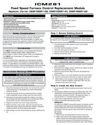
<strong><strong>ICM</strong>291</strong> <strong>Gas</strong> <strong>Ignition</strong> <strong>Control</strong> <strong>Board</strong><br />
FEATURES<br />
• Direct Spark <strong>Ignition</strong> (DSI) control board<br />
• Microprocessor-based<br />
• <strong>Control</strong>s combustion, blower and indoor motors; spark ignitor; and the gas valve<br />
• Monitors timing, trial for ignition, flame sensing and lockout<br />
• 100% lockout safety feature<br />
• Compatible with LP or Natural <strong>Gas</strong><br />
• Status LED for fault codes to aid in troubleshooting<br />
• Replaces: Carrier LH33WP003A<br />
SPECIFICATIONS<br />
• <strong>Control</strong> voltage: 24 VAC (18-30 VAC), 60 Hz<br />
• Line voltage: 208/230 VAC, 60 Hz<br />
• Power consumption: 0.3A plus gas valve current at 24 VAC<br />
• Operating Temperature: -40°C (-40°F) to 75°C (176°F)<br />
Timing<br />
• Pre-purge: 45 seconds<br />
• Trial for <strong>Ignition</strong>: 5+2 seconds<br />
• Retry period: every 20 sec. for 15 min.<br />
• Lockout: manual reset<br />
• Post-purge: 45 seconds<br />
Inputs<br />
• Power: RT and C<br />
• Thermostat interface: R, W and G<br />
• Safety switches: RS, LS, and CS<br />
• Combustion motor Hall Effect sensor<br />
• Flame Sensing<br />
LED indicators<br />
• Red LED: Steady ON- normal operation<br />
Flashing - fault codes<br />
Outputs<br />
• Spark<br />
• <strong>Gas</strong> Valve: GV<br />
• Combustion motor: CM<br />
• Blower motor: BM<br />
• Indoor fan motor: IFO<br />
Safety Considerations<br />
Only trained personnel should install or service heating equipment. When working with heating<br />
equipment, be sure to read and understand all precautions in the documentation, on labels, and on<br />
tags that accompany the equipment. Failure to follow all safety guidelines may result in damage to<br />
equipment, severe personal injury or death.<br />
Introduction<br />
The <strong><strong>ICM</strong>291</strong> DSI gas ignition control replaces the following Carrier model: LH33WP003A. The<br />
<strong><strong>ICM</strong>291</strong> has incorporated LED diagnostics to assist in troubleshooting. Fault code information can be<br />
found in this application guide. Please keep this application guide with the furnace installation manual<br />
for future reference.<br />
Electrostatic Discharge (ESD) Precautions<br />
CAUTION!<br />
Use caution when installing and servicing the furnace to avoid and control electrostatic discharge;<br />
ESD can impact electronic components. These precautions must be followed to prevent<br />
electrostatic discharge from hand tools and personnel. Following the precautions will protect the<br />
control from ESD by discharging static electricity buildup to ground.<br />
1. Disconnect all power to the furnace. Do not touch the control or the wiring prior to discharging your<br />
body’s electrostatic charge to ground.<br />
2. To ground yourself, touch your hand and tools to a clean, metal (unpainted) furnace surface near<br />
the control board.<br />
3. Service the furnace after touching the chassis. Your body will recharge with static electricity as you<br />
shuffle your feet or move around, and you must reground yourself.<br />
4. Reground yourself if you touch ungrounded items.<br />
5. Before handling a new control, reground yourself; this will protect the control. Store used and new<br />
controls in separate containers before touching ungrounded objects.<br />
6. ESD damage can also be prevented by using an ESD service kit.<br />
Remove Existing <strong>Control</strong><br />
CAUTION!<br />
To service control, and prior to disconnection, label all wires. Failure to do so may result in wiring<br />
errors that can cause dangerous operation.<br />
1. Turn thermostat to OFF position or set it to the lowest possible setting.<br />
2. Turn OFF electrical supply to furnace.<br />
3. Turn OFF gas supply to furnace.<br />
CAUTION: Failure to turn off gas and electric supplies can result in explosion, fire, death, or<br />
personal injury.<br />
4. Remove furnace blower and control access doors.<br />
5. Disconnect thermostat wires and humidifier wires (if equipped with a humidifier).<br />
6. Disconnect line voltage, blower, electronic air cleaner wires (if equipped), and transformer wires.<br />
7. Remove screws and any other fasteners, and the old circuit board.<br />
8. Examine control and control box to check for water stains.<br />
9. Make repairs if any sources of water leakage are found. Be sure to check humidifiers, evaporator<br />
coils, and vent systems in the area of the control.<br />
Install New <strong>Control</strong><br />
1. Ground yourself. When handling circuit board, hold it by the edges.<br />
2. Fasten circuit board with retaining screws.<br />
3. Connect all line voltage, low voltage, and accessory wires.<br />
4. Verify the sequence of operation.<br />
Troubleshooting Tips<br />
Flame not established<br />
1. If flame is not established during the 5+2 initial sequence then the control will start the next trial for<br />
ignition in 20 seconds.<br />
2. The attempt to ignite will continue for 15 minutes before the respective fault code is triggered and<br />
ignition trials are stopped.<br />
3. The gas valve is energized only during the ignition sequence of 5+2 seconds.<br />
4. Blower and indoor fan motors are off until flame is established and 45 seconds later.<br />
Flame out<br />
1. Flame out is considered when flame is lost during heating.<br />
2. When W signal is present and flame is sensed out then the spark will start right away.<br />
3. If flame is not established on the immediate sequence (2 above) then the control will continue<br />
attempts every 20 seconds for 15 minutes before the respective fault code is triggered and ignition<br />
trials are stopped.<br />
4. Blower and indoor fan motors will continue running during flame out scenario for 15 minutes + 45<br />
seconds.<br />
5. Combustion motor remains on throughout the flame out scenario.<br />
Flame out of sequence<br />
1. Flame out of sequence represents a scenario when flame is sensed while W signal is not present.<br />
2. Combustion, blower and indoor fan motors will be engaged (if not already running) right away and<br />
keep running for as long as the fault condition is present.<br />
3. The unit is operable but will display the fault code constantly until replaced by another fault code or<br />
power reset.<br />
No signal from the Hall affect sensor<br />
1. On a W call, if the input from the Hall affect sensor (RA0) is not present for more than a minute,<br />
then the combustion motor will continue running endlessly and the respective fault is flashed.<br />
2. During running state if the input from the Hall affect sensor is not sensed then the gas valve will<br />
shut off right away, blower and indoor fan motors will continue running for 30 seconds and then<br />
turn off, combustion motor runs continuously.<br />
LED Fault Codes<br />
# Of Flashes<br />
represents Constant<br />
Results<br />
ON Normal<br />
operation<br />
The control has modified the fan on delay to 0 and off delay to 3 minutes<br />
1<br />
due to sensing LS trip within 10 minutes of a call<br />
a) LS is open due to high temperature (fan isn’t working scenario)<br />
2<br />
b) The unit will not start a trial for ignition until the switch closes back<br />
a) Flame sensed out of sequence.<br />
3<br />
b) The unit is operable, however will display this fault code until power<br />
reset or another code<br />
a) LS opened 4 consecutive times during a call for heating<br />
4<br />
b) The fault code is reset on the next W call<br />
a) <strong>Ignition</strong> lockout. The control tried unsuccessfully to ignite for 15 minutes<br />
5<br />
b) The unit will not operate. Requires power reset<br />
a) The combustion motor is not sensed running OR CS open<br />
6<br />
b) The unit will not operate. Requires power reset<br />
a) RS tripped<br />
7<br />
b) The unit will not operate. Requires power reset<br />
8 a) Internal control fault (software self check)<br />
Sequence of Operation<br />
A W call from the T’stat will engage the combustion motor. <strong>Ignition</strong> sequence begins, gas valve and<br />
spark are engaged, providing that system safety switches (RS, LS, and CS) are closed and there is<br />
feedback from the combustion motor Hall Effect sensor. The blower and indoor motors will engage 45<br />
seconds after flame is established and sensed. They disengage 45 seconds after W call is satisfied.<br />
A G call from the T’stat will engage blower and indoor motors right away. They disengage 25 seconds<br />
after G call is removed.<br />
<strong>ICM</strong> CONTROLS 7313 William Barry Blvd.<br />
800.365.5525<br />
www.icmcontrols.com<br />
North Syracuse, NY 13212<br />
LIAF098
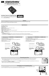
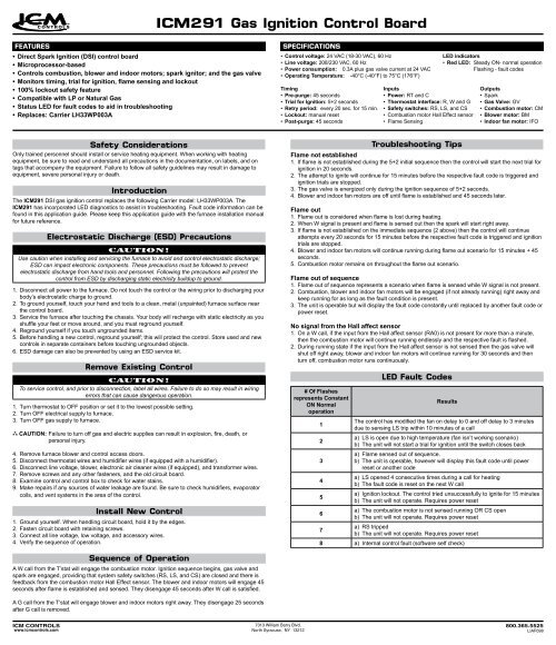
Typical Wiring Diagram<br />
Field Splice<br />
Terminal (marked)<br />
Terminal (unmarked)<br />
Splice<br />
Splice (marked)<br />
Factory Wiring<br />
Field <strong>Control</strong> Wiring<br />
Field Power Wiring<br />
Accessory or Optional Wiring<br />
To Indicate Common Potential<br />
Only: Not to Represent Wiring<br />
BR Blower Relay<br />
C Contactor<br />
CAP Capacitor<br />
COMP Compressor Motor<br />
CR Combustion Relay<br />
EQUIP Equipment<br />
FS Flame Sensor<br />
FU Fuse<br />
LEGEND<br />
GND Ground<br />
GVR <strong>Gas</strong> Valve Relay<br />
HPS High Pressure Switch<br />
HS Hall Effect Sensor<br />
HV TRAN High Voltage Transformer<br />
I Ignitor<br />
<strong>ICM</strong> Integrated <strong>Control</strong> Motor<br />
IDM Induced Draft Motor<br />
IFM Indoor Fan Motor<br />
IGC Integrated <strong>Gas</strong> Unit<br />
<strong>Control</strong>ler<br />
IMR Indoor Motor Relay<br />
LPS Low Pressure Switch<br />
LS Limit Switch<br />
MGV Main <strong>Gas</strong> Valve<br />
OFM Outdoor Fan Motor<br />
QT Quadruple Terminal<br />
RS Rollover Switch<br />
TRAN Transformer