INCIDENT Aircraft Type and Registration: Airbus A321 ... - SKYbrary
INCIDENT Aircraft Type and Registration: Airbus A321 ... - SKYbrary
INCIDENT Aircraft Type and Registration: Airbus A321 ... - SKYbrary

Create successful ePaper yourself
Turn your PDF publications into a flip-book with our unique Google optimized e-Paper software.
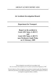
AAIB Bulletin: 10/2011 G-MEDJ EW/C2010/08/08<br />
<strong>INCIDENT</strong><br />
<strong>Aircraft</strong> <strong>Type</strong> <strong>and</strong> <strong>Registration</strong>: <strong>Airbus</strong> <strong>A321</strong>-231, G-MEDJ<br />
No & <strong>Type</strong> of Engines: 2 International Aero Engines V2533-A5 turbofan engines<br />
Year of Manufacture & Serial No: 2004, MSN 2190<br />
Date & Time (UTC): 24 August 2010 at 0225 hrs<br />
Location: At FL360 over northern Sudan<br />
<strong>Type</strong> of Flight: Commercial Air Transport (Passenger)<br />
Persons on Board: Crew - 7 Passengers - 42<br />
Injuries: Crew - None Passengers - None<br />
Nature of Damage: None<br />
Comm<strong>and</strong>er’s Licence: Airline Transport Pilot’s Licence<br />
Comm<strong>and</strong>er’s Age: 34 years<br />
Comm<strong>and</strong>er’s Flying Experience: Approximately 7,500 hours (of which approximately<br />
1,400 were on type)<br />
Last 90 days - 165 hours<br />
Last 28 days - 61 hours<br />
Information Source: AAIB Field Investigation<br />
Synopsis<br />
The aircraft suffered an electrical malfunction during<br />
a scheduled night flight between Khartoum (Sudan)<br />
<strong>and</strong> Beirut (Lebanon). The more significant symptoms<br />
included the intermittent failure of the captain <strong>and</strong><br />
co-pilot’s electronic displays <strong>and</strong> the uncomm<strong>and</strong>ed<br />
application of left rudder trim, which was not annunciated<br />
to the flight crew. The flight crew also reported that the<br />
aircraft did not seem to respond as expected to control<br />
inputs. A large number of ECAM 1 messages <strong>and</strong><br />
cautions were presented on the pilots’ electronic display<br />
Footnote<br />
1 Electronic Centralised <strong>Aircraft</strong> Monitoring system – this<br />
comprises two centrally mounted electronic display units, which<br />
present the flight crew with aircraft systems information, warning<br />
<strong>and</strong> memo messages <strong>and</strong> actions to be taken in response to systems<br />
failures.<br />
© Crown copyright 2011<br />
1<br />
units. The uncomm<strong>and</strong>ed rudder trim caused the aircraft<br />
to adopt a left-wing-low attitude <strong>and</strong> deviate to the left<br />
of the planned track. Normal functions were restored<br />
after the flight crew selected the No 1 generator to OFF in<br />
response to an ‘ELEC GEN 1 FAULT’ message. The aircraft<br />
l<strong>and</strong>ed safely at Beirut.<br />
The No 1 generator was replaced, after which the fault<br />
did not recur. Damage was found on an electrical lead<br />
on the No 1 generator, but it could not be determined<br />
whether this had caused the symptoms experienced<br />
during the incident.<br />
The aircraft manufacturer notified operators of<br />
this incident by issuing OIT 999.0105/10 on
AAIB Bulletin: 10/2011 G-MEDJ EW/C2010/08/08<br />
19 November 2010 <strong>and</strong> also updated the Quick<br />
Reference H<strong>and</strong>book procedure for ‘Display Unit<br />
Failure’ to include a check of the rudder trim position.<br />
History of the flight<br />
The incident occurred as the aircraft was cruising at<br />
Flight Level (FL) 360 over northern Sudan, with the<br />
comm<strong>and</strong>er as pilot flying <strong>and</strong> the No 1 autopilot (AP 1)<br />
<strong>and</strong> autothrust engaged. The conditions were night<br />
Instrument Meteorological Conditions, with slight<br />
turbulence. The comm<strong>and</strong>er reported that, without<br />
warning, his Primary Flight Display (PFD), Navigation<br />
Display (ND), <strong>and</strong> the ECAM upper Display Unit (DU)<br />
began to flicker, grey out, show lines or crosses, <strong>and</strong><br />
go blank. Concurrently, there was a “chattering” heard<br />
coming from the rear circuit breaker panels, behind<br />
the two pilots’ seats, which was thought to be relay<br />
operation. The abnormal behaviour ceased after a short<br />
time. The co-pilot checked the circuit breakers to see if<br />
any had operated <strong>and</strong> to look for signs of overheating,<br />
but nothing unusual was noted. The comm<strong>and</strong>er<br />
reviewed the ECAM electrical system page, which<br />
showed no abnormalities.<br />
After a short interval the comm<strong>and</strong>er’s PFD, ND,<br />
<strong>and</strong> ECAM upper DU began to flicker <strong>and</strong> grey out<br />
again, before blanking for longer periods. AP 1 was<br />
disconnected <strong>and</strong> the comm<strong>and</strong>er h<strong>and</strong>ed control to the<br />
co-pilot, whose display screens were unaffected at this<br />
time. The abnormal condition was once again short-<br />
lived <strong>and</strong> once conditions had returned to normal, the<br />
comm<strong>and</strong>er reassumed control <strong>and</strong> re-engaged AP 1.<br />
The symptoms returned shortly thereafter, with the<br />
comm<strong>and</strong>er’s displays becoming mostly blank, or<br />
showing white lines. When the displays were visible,<br />
the airspeed, altimeter, <strong>and</strong> QNH/STD indications were<br />
erratic. The co-pilot’s PFD, ND, <strong>and</strong> the ECAM lower<br />
© Crown copyright 2011<br />
2<br />
DU began to flicker <strong>and</strong> were sometimes unreadable.<br />
The crew reported that the cockpit lights went off<br />
intermittently. The comm<strong>and</strong>er h<strong>and</strong>ed control to<br />
the co‑pilot again, who flew the aircraft manually.<br />
Reference was made to the st<strong>and</strong>by flight instruments,<br />
which operated normally throughout the incident.<br />
During this period, the chattering sound from the<br />
rear circuit breaker panels resumed <strong>and</strong> was, at<br />
times, continuous. Numerous ECAM messages were<br />
presented <strong>and</strong> there were a number of master caution<br />
annunciations. Amber ‘X’ symbols indicating flight<br />
control system reconfiguration to Alternate Law 2<br />
appeared on the PFDs, the flight directors were<br />
displayed only intermittently <strong>and</strong> the autothrust system<br />
went into ‘thrust lock’ mode. The aircraft rolled to the<br />
left <strong>and</strong> adopted an approximately 10º left-wing-low<br />
attitude, without any flight control input from the<br />
crew. The flight crew reported that the aircraft did not<br />
seem to respond as expected to their control inputs <strong>and</strong><br />
shuddered <strong>and</strong> jolted repeatedly.<br />
The comm<strong>and</strong>er recalled selecting the Display<br />
Management Computer (DMC) switch from ‘NORM’ to<br />
‘CAPT 3’ to switch the source for the captain’s displays<br />
from DMC 1 to DMC 3, but this had no effect in restoring<br />
his displays. The switch was left in the ‘CAPT 3’ position<br />
for the remainder of the flight.<br />
The flight crew became concerned that the aircraft<br />
was malfunctioning. The ECAM was only sometimes<br />
visible <strong>and</strong> did not identify the root cause of the problem<br />
<strong>and</strong> there were no fault indications visible on the<br />
overhead panel. Moreover, they were not aware of any<br />
procedure applicable to the symptoms experienced. The<br />
Footnote<br />
2 Alternate Law is a mode of the flight control system in which<br />
certain protection features are unavailable.
AAIB Bulletin: 10/2011 G-MEDJ EW/C2010/08/08<br />
comm<strong>and</strong>er contemplated transmitting a MAYDAY,<br />
but considered that his priorities were to retain control<br />
of the aircraft <strong>and</strong> identify the problem.<br />
At one point the comm<strong>and</strong>er saw the ECAM ‘ELEC<br />
GEN 1 FAULT’ message <strong>and</strong> associated checklist appear<br />
momentarily. The checklist required the No 1 generator<br />
to be selected to OFF. On doing so the juddering motion<br />
ceased, the chattering noise stopped, <strong>and</strong> all displays<br />
reverted to normal operation, although the aircraft’s<br />
left-wing-low attitude persisted. The checklist directed<br />
that the generator should be selected ON again, <strong>and</strong><br />
following discussion <strong>and</strong> agreement that it would be<br />
immediately deselected should the problems return, the<br />
comm<strong>and</strong>er selected it to ON. This caused the symptoms<br />
to return, prompting him to select it to OFF again.<br />
The Auxiliary Power Unit was started <strong>and</strong> its generator<br />
was selected to power the systems previously powered<br />
by the No 1 generator. Shortly thereafter, the flight crew<br />
noticed that the rudder trim display indicated several<br />
units from neutral 3 , although they had not made any<br />
rudder trim inputs. When the rudder trim was reset to<br />
neutral, the aircraft readopted a wings-level attitude.<br />
The aircraft had deviated approximately 20 nm to the<br />
left of the intended track during the incident.<br />
The aircraft was flown manually for the remainder of the<br />
flight <strong>and</strong> l<strong>and</strong>ed at Beirut without further incident.<br />
The aircraft was inspected in Beirut <strong>and</strong> the No 1<br />
Integrated Drive Generator (IDG1) was removed as<br />
unserviceable <strong>and</strong> sent for overhaul. There was no<br />
recurrence of the symptoms reported in this incident in<br />
subsequent flights.<br />
Footnote<br />
3 The rudder trim indicator is at the rear of the centre pedestal.<br />
© Crown copyright 2011<br />
3<br />
Reporting of the event<br />
The comm<strong>and</strong>er reported the event shortly after arrival,<br />
both verbally by telephone to his managers, <strong>and</strong> in<br />
writing using an Air Safety Report (ASR) form which<br />
was placed in the operator’s internal mail system when<br />
the flight crew returned to the UK. However, the full<br />
significance of the event was not apparent during the<br />
telephone call <strong>and</strong> the ASR form became lost in the<br />
operator’s internal paperwork system. Consequently, an<br />
investigation was not commenced until several weeks<br />
later, when the comm<strong>and</strong>er enquired as to what progress<br />
had been made in finding the cause of the event. The<br />
operator stated that it had since taken actions to improve<br />
its processes for the reporting <strong>and</strong> tracking of air safety<br />
incidents.<br />
Flight recorders<br />
Because of the late notification of the event to the<br />
AAIB, both the Cockpit Voice Recorder (CVR) <strong>and</strong> the<br />
Flight Data Recorder (FDR) data for the incident were<br />
overwritten. Attempts were made to obtain information<br />
from various sources of non-volatile memory; however,<br />
such was the delay in reporting the incident, no<br />
information from the incident flight was available.<br />
However, flight data was obtained from the operator’s<br />
Flight Data Monitoring (FDM) programme, which<br />
recorded a similar set of parameters to the FDR. The<br />
systems associated with the FDM were powered by<br />
the No 2 electrical supply <strong>and</strong> so continued recording<br />
throughout the event.<br />
Recorded parameters associated with the electrical<br />
supply system showed no loss of the AC 1, AC 2, DC 1<br />
or DC 2 supplies 4 throughout the flight. However, these<br />
Footnote<br />
4 AC denotes alternating current <strong>and</strong> DC denotes direct current.
AAIB Bulletin: 10/2011 G-MEDJ EW/C2010/08/08<br />
parameters were only recorded every four seconds so a<br />
transient interruption may not have been captured. The<br />
status of each of the electrical system contactors was<br />
not recorded but some recorded parameters exhibited<br />
signs of electrical transients, as evidenced by data spikes<br />
during each power reset.<br />
The recorded data largely confirmed the flight crew’s<br />
recollections. The effects of electrical transients were<br />
recorded at 0225 hrs <strong>and</strong> 0237 hrs. At 0240:00 hrs,<br />
further transients were recorded, this time leading to<br />
an increase in the recorded rudder position from 0° to<br />
+3.6° within 20 seconds (rudder trim was not recorded).<br />
Positive rudder deflection is deflection of the surface<br />
to the left which causes the aircraft to yaw to the left.<br />
As the secondary effect of yaw is roll, the aircraft then<br />
rolled to the left. The autopilot attempted to counter this<br />
with a right roll comm<strong>and</strong> <strong>and</strong> associated aileron <strong>and</strong> roll<br />
spoiler deflection.<br />
At 0240:16 hrs, the recorded ‘DMC transfer’ parameter<br />
changed state, representing the DMC switch moving<br />
from the ‘NORM’ position to either the ‘CAPT 3’ or<br />
the ‘F/O 3’ position. Two seconds later, the autopilot<br />
disconnected <strong>and</strong> the roll angle increased to a maximum<br />
of 11.6° to the left before the co-pilot levelled the wings<br />
by comm<strong>and</strong>ing right roll with the sidestick.<br />
The autopilot was re-engaged but the aircraft continued<br />
to yaw left as the rudder position remained at +3.6°.<br />
This again induced a left roll which was countered by the<br />
flight director comm<strong>and</strong>ing a right roll input. However,<br />
with the autopilot engaged <strong>and</strong> at an airspeed of 260 kt,<br />
the control surface deflection is automatically limited<br />
to ±9° for the ailerons <strong>and</strong> 4° for the roll spoilers. As<br />
a result, there was insufficient roll authority to allow<br />
the autopilot to roll the aircraft level <strong>and</strong> the aircraft<br />
continued to roll left to a maximum roll angle of 11°.<br />
© Crown copyright 2011<br />
4<br />
At this point, the rudder deflection was +3.6° with the<br />
right aileron deflected 9° down, left aileron 9° up, right<br />
roll spoilers deflected to 4° <strong>and</strong> the aircraft heading<br />
decreasing at 0.5° per second.<br />
The autopilot then disconnected <strong>and</strong> the aircraft was<br />
flown manually. In manual flight, the travel limits for<br />
the ailerons <strong>and</strong> roll spoilers are their maximum travel<br />
(±25° <strong>and</strong> 35° respectively). As a result, each time the<br />
autopilot was re-engaged, the aircraft rolled to the left<br />
<strong>and</strong> when disconnected, the co-pilot’s control inputs<br />
were sufficient to maintain a wings‑level attitude.<br />
After the final autopilot disengagement at 0245 hrs, the<br />
aircraft was flown manually for the rest of the flight. At<br />
0246:31 hrs, the rudder position began reducing from<br />
+3.6° to zero over a period of 17 seconds, six <strong>and</strong> a half<br />
minutes after the rudder surface first moved from the<br />
zero position.<br />
Manufacturer’s simulation<br />
The aircraft manufacturer performed a simulation using<br />
the data available from this incident <strong>and</strong> reported that<br />
the aircraft performance was as expected. They also<br />
confirmed that in the event of maximum rudder trim<br />
being applied at this airspeed, sufficient aileron authority<br />
is available in manual flight to maintain the desired flight<br />
path.<br />
<strong>Aircraft</strong> information<br />
General<br />
The A320 family of aircraft has extensive electrical<br />
services, fed from a system that broadly comprises two<br />
electrical networks, a left <strong>and</strong> a right, denoted No 1<br />
<strong>and</strong> No 2, respectively. No 1 <strong>and</strong> No 2 networks are<br />
normally independent of one another, so that the failure<br />
of one network should not adversely affect the other.<br />
The power supplies for flight‑critical systems are for
AAIB Bulletin: 10/2011 G-MEDJ EW/C2010/08/08<br />
the most part segregated, with the aim that the loss of<br />
a single power source should not result in concurrent<br />
failures of systems necessary for continued safe flight.<br />
Electrical power generation system<br />
The electrical system is powered primarily from AC<br />
sources (3-phase, 115/200 Volt (V) at a frequency of<br />
400 Hz). Two engine-driven generators, one mounted<br />
on each engine, normally power the system. Each<br />
generator is driven from the engine high-pressure<br />
spool via an engine accessory gearbox <strong>and</strong> an<br />
integrated hydro-mechanical speed regulator. The<br />
regulator transforms variable engine rotational speed<br />
into a constant-speed drive for the generator. The<br />
constant-speed drive <strong>and</strong> the generator collectively<br />
form an assembly known as the Integrated Drive<br />
Generator (IDG).<br />
Mounted externally on each IDG is an electrical cable<br />
referred to as the ‘jumper lead’. This is for maintenance<br />
purposes <strong>and</strong> to provide commonality between different<br />
electrical system st<strong>and</strong>ards. The generator manufacturer<br />
uses several different suppliers for this lead. The lead<br />
is approximately 20 cm long <strong>and</strong> is formed into a tight<br />
180° bend with a connector at each end. The jumper<br />
lead is supported halfway along its length by a ‘P’ clip.<br />
The lead comprises an outer protective layer, a layer<br />
of woven metal braid, <strong>and</strong> then seven individual wire<br />
cables. Each of the seven individual cables comprises<br />
an outer insulation layer, a layer of woven insulation<br />
<strong>and</strong> thin foil, <strong>and</strong> a central multi-str<strong>and</strong> electrical wire.<br />
A Generator Control Unit (GCU) associated with<br />
each IDG monitors the IDG output <strong>and</strong> opens the<br />
Generator Line Contactor (GLC) if it detects an<br />
aircraft‑manufacturer‑specified out‑of‑limits condition,<br />
thus isolating the IDG from the electrical system.<br />
© Crown copyright 2011<br />
5<br />
Electronic flight instrument system<br />
Information for the flight crew is presented primarily<br />
on an Electronic Flight Instrument System (EFIS),<br />
comprising six DUs on the flight deck forward panel.<br />
These include the PFD <strong>and</strong> ND in front of each pilot<br />
<strong>and</strong> two ECAM displays located one above the other on<br />
the central part of the panel (Figure 1). The ECAM is a<br />
tool to:<br />
● display aircraft system information<br />
● monitor aircraft systems<br />
● indicate required flight crew actions, in most<br />
normal, abnormal <strong>and</strong> emergency situations<br />
The DUs are driven by three identical DMCs, identified<br />
as DMC 1, 2 <strong>and</strong> 3. In the normal configuration, DMC 1<br />
(which is powered by the No 1 electrical system) drives<br />
the captain’s (left) PFD <strong>and</strong> ND, <strong>and</strong> the ECAM upper<br />
DU; DMC 2 (which is powered by the No 2 electrical<br />
system) drives the co-pilot’s (right) PFD <strong>and</strong> ND <strong>and</strong><br />
the ECAM lower DU. DMC 3 (which is normally<br />
powered by the No 1 electrical system) is available as a<br />
backup <strong>and</strong> can be manually selected to replace DMC 1<br />
or DMC 2.<br />
The DUs <strong>and</strong> DMCs have different transient response<br />
times in the event of a power loss. For the DUs this is<br />
around 25 ms <strong>and</strong> for the DMCs this is around 100 ms.<br />
In the event of an intermittent interruption in power to the<br />
No 1 electrical system <strong>and</strong> with DMC 3 selected to drive<br />
the co-pilot’s displays, the different transient response<br />
times of the DUs <strong>and</strong> DMCs are likely to produce a<br />
greater effect on the captain’s DUs than the co-pilot’s.<br />
Flight augmentation computers<br />
A320 family aircraft have two Flight Augmentation<br />
Computers: FAC 1 <strong>and</strong> FAC 2. These perform several<br />
functions, one of which is to provide input comm<strong>and</strong>s to
AAIB Bulletin: 10/2011 G-MEDJ EW/C2010/08/08<br />
the rudder trim actuator. The units operate with FAC 1<br />
having priority <strong>and</strong> they are powered by a 28V DC<br />
Essential bus. If the power supply goes below 16V for<br />
more than 10 ms the FAC units will reset. This causes<br />
an offset of approximately 0.2° of rudder trim to be<br />
comm<strong>and</strong>ed. Multiple resets result in cumulative rudder<br />
trim offsets. The rudder trim limits are determined by<br />
the Rudder Travel Limiter (varying from ±3° at high<br />
speed to ±30° at low speed) or, if the logic in the FAC<br />
for a rudder trim runaway is triggered, no further rudder<br />
trim is input. At the aircraft speed in this incident the<br />
maximum available rudder trim was ±7°.<br />
The aircraft manufacturer confirmed that a similar<br />
architecture is used on A330 aircraft <strong>and</strong> there is<br />
therefore the potential for a generator fault to cause<br />
similar problems with the DUs. However, no such faults<br />
have so far been reported on the A330 fleet in nearly<br />
19 million flying hours.<br />
© Crown copyright 2011<br />
Primary<br />
Flight<br />
Display<br />
CAPTAIN<br />
Upper<br />
ECAM<br />
Display<br />
CO-PILOT<br />
Navigation<br />
Display<br />
Figure 1<br />
6<br />
Lower<br />
ECAM<br />
Display<br />
Electronic Flight Instrument System<br />
Engineering investigation<br />
Post-flight report<br />
Although the fault memories of the onboard maintenance<br />
systems were overwritten, a copy of the Post-Flight<br />
Report (PFR) was available. This report contained<br />
23 flight deck warnings <strong>and</strong> 44 fault messages for the<br />
incident flight, mainly attributed to the loss of electrical<br />
supply to the No 1 network. Of note was an ‘AUTO<br />
FLT RUD TRIM1 FAULT’ ECAM warning indicating that<br />
FAC 1 had detected a rudder trim fault. This warning<br />
is for crew awareness only. Additionally, the PFR<br />
listed a ‘AFS: FAC1/RT ACTR 10CC’ fault message which<br />
is generated when the rudder trim runaway monitoring<br />
is triggered by FAC 1. The outcome of this failure<br />
message is that the rudder trim function in FAC 1 is<br />
disengaged <strong>and</strong> automatically transferred to FAC 2.
AAIB Bulletin: 10/2011 G-MEDJ EW/C2010/08/08<br />
IDG <strong>and</strong> GCU testing<br />
After the incident IDG1 was removed <strong>and</strong> sent for overhaul<br />
by the operator but nothing significant was found. When<br />
AAIB were notified of the event several weeks later, the<br />
IDG1 <strong>and</strong> GCU1 were quarantined <strong>and</strong> subsequently<br />
taken to the aircraft manufacturer’s ‘iron bird’ 5 test rig<br />
facility for a functional check <strong>and</strong> to attempt to simulate<br />
the characteristics of the incident flight. Although both<br />
units functioned normally on the rig, it was possible to<br />
create symptoms that appeared similar to those reported<br />
by the crew. When repeated electrical shorts at a certain<br />
frequency were simulated on either wire No 1 or wire No<br />
2 in the jumper lead, the DUs flickered, more so on the<br />
captain’s side, <strong>and</strong> small <strong>and</strong> cumulative increments in<br />
rudder trim were produced. However, these symptoms<br />
only occurred when the co-pilot’s DUs were selected to<br />
be powered by DMC 3. Other combinations of wires<br />
were equally exercised in this testing, but they did not<br />
produce these symptoms.<br />
IDG1 <strong>and</strong> GCU1 were then taken to their manufacturer<br />
for further inspection. The IDG was subjected to a<br />
detailed strip examination under AAIB supervision<br />
with experienced overhaul <strong>and</strong> design specialists from<br />
the manufacturer present. The jumper lead appeared<br />
distorted (Figure 2) <strong>and</strong> when the outer cover was<br />
removed significant material damage to the wire braid<br />
was found at both ends, near the connectors (Figure 3).<br />
The jumper lead was taken to a forensic laboratory for<br />
examination. Evidence that the str<strong>and</strong>s of wire braid had<br />
been chafing against each other was found (Figure 4).<br />
It was confirmed that wear marks made by the braid<br />
were present on the insulation of the seven wires inside<br />
Footnote<br />
5 The iron bird is a static test rig which allows aircraft systems to<br />
be tested in laboratory conditions in the presence of all the aircraft<br />
systems. It also has a representative cockpit for flight simulation.<br />
© Crown copyright 2011<br />
7<br />
the braided outer sheath (Figure 5). The insulation was<br />
worn down on some of the cables, exposing the central<br />
conductor inside. Some cables exhibited holes in the<br />
insulation containing debris that was confirmed by an<br />
EDAX 6 technique as being of the same composition as<br />
the wire braid. Using a Scanning Electron Microscope<br />
(SEM), evidence of arcing was found on wire No 5<br />
(Figure 6). Despite extensive efforts, it was not possible<br />
to positively identify arcing or a short on any of the other<br />
wires. It was concluded that the failure mechanism of<br />
Footnote<br />
Figure 2<br />
Jumper lead as removed<br />
Figure 3<br />
Jumper lead with outer cover removed<br />
6 Energy-dispersive X-ray spectroscopy which can be used to<br />
determine the composition of material.
AAIB Bulletin: 10/2011 G-MEDJ EW/C2010/08/08<br />
© Crown copyright 2011<br />
Figure 4<br />
Close up of wire braid on jumper lead showing<br />
evidence of chafing<br />
the jumper lead was the wire braid rubbing against the<br />
seven wires, with the vibration of the engine <strong>and</strong> the<br />
tight bend in the routing of the jumper lead providing<br />
the conditions conducive to wear. It was not clear if the<br />
‘P’ clip, mid-way along the jumper lead, was a factor in<br />
the failure mechanism.<br />
AAIB Special Bulletin S2/2010<br />
In November 2010 AAIB published a Special Bulletin<br />
which contained preliminary findings of the investigation<br />
<strong>and</strong> the following Safety Recommendation:<br />
Figure 6<br />
SEM image showing arcing damage on surface of<br />
str<strong>and</strong>s in wire No 5<br />
8<br />
Figure 5<br />
Close up of wire in jumper lead showing wear marks<br />
Safety Recommendation 2010-092<br />
It is recommended that <strong>Airbus</strong> alert all operators<br />
of A320-series aircraft of the possibility that an<br />
electrical power generation system fault may not<br />
be clearly annunciated on the ECAM, <strong>and</strong> may<br />
lead to uncomm<strong>and</strong>ed rudder trim operation.<br />
<strong>Airbus</strong> notified operators of this incident by the issue of<br />
OIT 999.0105/10, dated 19 November 2010.
AAIB Bulletin: 10/2011 G-MEDJ EW/C2010/08/08<br />
Analysis<br />
The delay in this incident being reported meant that<br />
potentially useful information in non-volatile memory,<br />
both in systems <strong>and</strong> the voice <strong>and</strong> data recorders was not<br />
available to the AAIB investigation. The delay in being<br />
able to interview the flight crew might have reduced the<br />
quality of their accounts.<br />
The incident appeared to have posed a number of<br />
challenges for the flight crew, in that they were presented<br />
with numerous <strong>and</strong> significant symptoms, including<br />
malfunctioning electronic displays <strong>and</strong> uncomm<strong>and</strong>ed<br />
rudder trim input, of which they were not aware, <strong>and</strong><br />
the cause of which was not evident. The ECAM did not<br />
clearly annunciate the root cause of the malfunction,<br />
nor were any fault captions observed on the overhead<br />
panel. No information or procedures were available<br />
to assist the flight crew in effectively diagnosing the<br />
problem.<br />
The aircraft manufacturer concluded that the aircraft<br />
responded as expected to the rudder trim inputs, which<br />
suggests that the rudder input alone was responsible for<br />
the divergence from the intended flight path. The ‘ELEC<br />
GEN 1 FAULT’ message during the incident, the resolution<br />
of the problem in flight when IDG1 was switched off<br />
<strong>and</strong> the lack of any further reported problems after<br />
IDG1 was replaced are good evidence that IDG1 had<br />
a fault which had affected aircraft equipment, causing<br />
the incremental rudder trim inputs.<br />
The symptoms experienced during the incident may<br />
have been attributable to a short in the jumper lead<br />
on IDG1. Whilst the lead was clearly damaged, <strong>and</strong><br />
© Crown copyright 2011<br />
9<br />
a plausible failure mechanism identified, this was only<br />
valid if DMC 3 was selected to power the co-pilot’s<br />
DUs, which is inconsistent with the crew’s report.<br />
Safety action<br />
As a result of other incidents involving blanking display<br />
units, the aircraft manufacturer was, at the time of this<br />
incident, developing an update to the Quick Reference<br />
H<strong>and</strong>book (QRH) for display unit failures. Whilst it was<br />
not possible to determine with any degree of certainty the<br />
cause of this incident, as a result of this investigation the<br />
QRH update was amended to account for the possibility<br />
that rudder trim could be affected (Figure 7).<br />
Figure 7<br />
Updated page from Quick Reference H<strong>and</strong>book