LM24-MFT US (LR24-MFT US) - Viking Controls, Inc.
LM24-MFT US (LR24-MFT US) - Viking Controls, Inc.
LM24-MFT US (LR24-MFT US) - Viking Controls, Inc.

You also want an ePaper? Increase the reach of your titles
YUMPU automatically turns print PDFs into web optimized ePapers that Google loves.
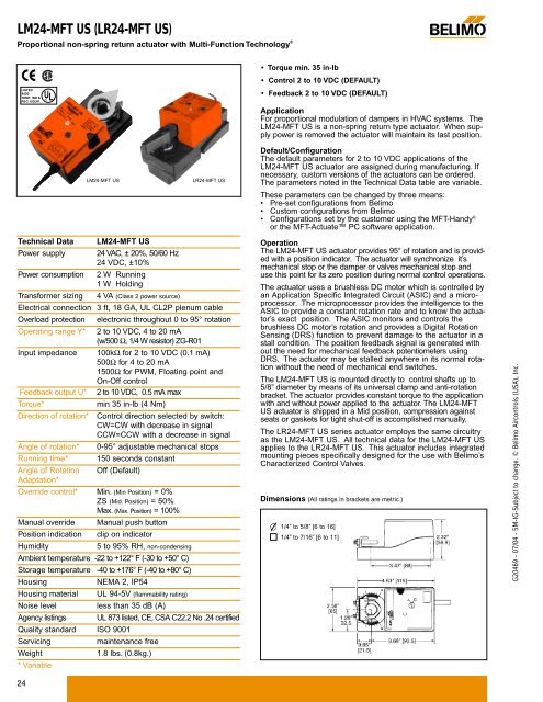
<strong>LM24</strong>-<strong>MFT</strong> <strong>US</strong> (<strong>LR24</strong>-<strong>MFT</strong> <strong>US</strong>)<br />
Proportional non-spring return actuator with Multi-Function Technology ®<br />
®<br />
LISTED<br />
94D5<br />
TEMP. IND &<br />
REG. EQUIP.<br />
UL ®<br />
• Torque min. 35 in-lb<br />
• Control 2 to 10 VDC (DEFAULT)<br />
• Feedback 2 to 10 VDC (DEFAULT)<br />
Application<br />
For proportional modulation of dampers in HVAC systems. The<br />
<strong>LM24</strong>-<strong>MFT</strong> <strong>US</strong> is a non-spring return type actuator. When supply<br />
power is removed the actuator will maintain its last position.<br />
Technical Data<br />
Power supply<br />
Power consumption<br />
Transformer sizing<br />
<strong>LM24</strong>-<strong>MFT</strong> <strong>US</strong><br />
24 VAC, ± 20%, 50/60 Hz<br />
24 VDC, ±10%<br />
2 W Running<br />
1 W Holding<br />
4 VA (Class 2 power source)<br />
Electrical connection 3 ft, 18 GA, UL CL2P plenum cable<br />
Overload protection<br />
Operating range Y*<br />
Input impedance<br />
Feedback output U*<br />
Torque*<br />
Direction of rotation*<br />
Angle of rotation*<br />
electronic throughout 0 to 95° rotation<br />
2 to 10 VDC, 4 to 20 mA<br />
(w/500 Ω, 1/4 W resistor) ZG-R01<br />
100kΩ for 2 to 10 VDC (0.1 mA)<br />
500Ω for 4 to 20 mA<br />
1500Ω for PWM, Floating point and<br />
On-Off control<br />
2 to 10 VDC, 0.5 mA max<br />
min 35 in-lb (4 Nm)<br />
Control direction selected by switch:<br />
CW=CW with decrease in signal<br />
CCW=CCW with a decrease in signal<br />
0-95° adjustable mechanical stops<br />
Running time* 150 seconds constant<br />
Angle of Rotation Off (Default)<br />
Adaptation*<br />
Override control* Min. (Min Position) = 0%<br />
ZS (Mid. Position) = 50%<br />
Max. (Max. Position) = 100%<br />
Manual override Manual push button<br />
Position indication clip on indicator<br />
Humidity<br />
5 to 95% RH, non-condensing<br />
Ambient temperature -22 to +122° F (-30 to +50° C)<br />
Storage temperature -40 to +176° F (-40 to +80° C)<br />
Housing<br />
Housing material<br />
Noise level<br />
Agency listings<br />
NEMA 2, IP54<br />
Quality standard ISO 9001<br />
Servicing<br />
Weight<br />
* Variable<br />
<strong>LM24</strong>-<strong>MFT</strong> <strong>US</strong><br />
UL 94-5V (flammability rating)<br />
less than 35 dB (A)<br />
UL 873 listed, CE, CSA C22.2 No .24 certified<br />
maintenance free<br />
1.8 lbs. (0.8kg.)<br />
<strong>LR24</strong>-<strong>MFT</strong> <strong>US</strong><br />
Default/Configuration<br />
The default parameters for 2 to 10 VDC applications of the<br />
<strong>LM24</strong>-<strong>MFT</strong> <strong>US</strong> actuator are assigned during manufacturing. If<br />
necessary, custom versions of the actuators can be ordered.<br />
The parameters noted in the Technical Data table are variable.<br />
These parameters can be changed by three means:<br />
• Pre-set configurations from Belimo<br />
• Custom configurations from Belimo<br />
• Configurations set by the customer using the <strong>MFT</strong>-Handy ®<br />
or the <strong>MFT</strong>-Actuate PC software application.<br />
Operation<br />
The <strong>LM24</strong>-<strong>MFT</strong> <strong>US</strong> actuator provides 95° of rotation and is provided<br />
with a position indicator. The actuator will synchronize it’s<br />
mechanical stop or the damper or valves mechanical stop and<br />
use this point for its zero position during normal control operations.<br />
The actuator uses a brushless DC motor which is controlled by<br />
an Application Specific Integrated Circuit (ASIC) and a microprocessor.<br />
The microprocessor provides the intelligence to the<br />
ASIC to provide a constant rotation rate and to know the actuator’s<br />
exact position. The ASIC monitors and controls the<br />
brushless DC motor’s rotation and provides a Digital Rotation<br />
Sensing (DRS) function to prevent damage to the actuator in a<br />
stall condition. The position feedback signal is generated with<br />
out the need for mechanical feedback potentiometers using<br />
DRS. The actuator may be stalled anywhere in its normal rotation<br />
without the need of mechanical end switches.<br />
The <strong>LM24</strong>-<strong>MFT</strong> <strong>US</strong> is mounted directly to control shafts up to<br />
5/8” diameter by means of its universal clamp and anti-rotation<br />
bracket. The actuator provides constant torque to the application<br />
with and without power applied to the actuator. The <strong>LM24</strong>-<strong>MFT</strong><br />
<strong>US</strong> actuator is shipped in a Mid position, compression against<br />
seats or gaskets for tight shut-off is accomplished manually.<br />
The <strong>LR24</strong>-<strong>MFT</strong> <strong>US</strong> series actuator employs the same circuitry<br />
as the <strong>LM24</strong>-<strong>MFT</strong> <strong>US</strong>. All technical data for the <strong>LM24</strong>-<strong>MFT</strong> <strong>US</strong><br />
applies to the <strong>LR24</strong>-<strong>MFT</strong> <strong>US</strong>. This actuator includes integrated<br />
mounting pieces specifically designed for the use with Belimo’s<br />
Characterized Control Valves.<br />
Dimensions (All ratings in brackets are metric.)<br />
1/4” to 5/8” [6 to 16]<br />
1/4” to 7/16” [6 to 11]<br />
G20469 - 07/04 - 5M-IG-Subject to change. © Belimo Aircontrols (<strong>US</strong>A), <strong>Inc</strong>.<br />
24
®<br />
<strong>LM24</strong>-<strong>MFT</strong> <strong>US</strong> (<strong>LR24</strong>-<strong>MFT</strong> <strong>US</strong>)<br />
Proportional non-spring return actuator with Multi-Function Technology ®<br />
24 VAC Transformer<br />
1<br />
Line<br />
Volts<br />
3<br />
Control Signal (–)<br />
2 to 10 VDC (+)<br />
2 to 10 VDC Feedback Signal<br />
Standard Wiring<br />
2<br />
Blk (1) Common<br />
Red (2) + Hot<br />
3<br />
Wht (3) Y 1 Input, 2 to 10V<br />
Grn (5) U Output, 2 to 10V<br />
W038<br />
24 VAC Transformer<br />
1<br />
Line<br />
Volts<br />
3<br />
Control Signal<br />
4 to 20 mA<br />
(–)<br />
(+)<br />
4<br />
Standard Wiring<br />
Ω 500Ω 1/4 watt<br />
2 to 10 VDC Feedback Signal<br />
2<br />
Blk (1) Common<br />
Red (2) + Hot<br />
3<br />
Wht (3) Y 1 Input, 2 to 10V<br />
Grn (5) U Output, 2 to 10V<br />
W039<br />
CCW(L) CW(R)<br />
<strong>LM24</strong>-<strong>MFT</strong> <strong>US</strong><br />
<strong>LR24</strong>-<strong>MFT</strong> <strong>US</strong><br />
CCW(L) CW(R)<br />
<strong>LM24</strong>-<strong>MFT</strong> <strong>US</strong><br />
<strong>LR24</strong>-<strong>MFT</strong> <strong>US</strong><br />
24 VAC Transformer<br />
1<br />
Line<br />
Volts<br />
3<br />
Control Signal (–) A<br />
2<br />
2 to 10 VDC (+)<br />
A Open = 0 V Position<br />
A Closed = Normal Operation<br />
Override to zero position<br />
Blk (1) Common<br />
Red (2) + Hot<br />
Wht (3) Y 1 Input, 2 to 10V<br />
Override to zero position<br />
24 VAC Transformer<br />
1<br />
Line<br />
Volts<br />
Blk (1) Common<br />
Red (2) + Hot<br />
3<br />
Ω 500Ω 1/4 watt 2<br />
Control Signal (–)<br />
4 to 20 mA (+)<br />
4<br />
A<br />
Wht (3) Y 1 Input, 2 to 10V<br />
A Open = 4 mA Position<br />
A Closed = Normal Operation<br />
G20469 - 07/04 - 5M-IG-Subject to change. © Belimo Aircontrols (<strong>US</strong>A), <strong>Inc</strong>.<br />
1<br />
Line<br />
Volts<br />
24 VAC Transformer<br />
3<br />
Control Signal (–) B 2<br />
2 to 10 VDC<br />
(+)<br />
C<br />
B Closed = 10 V Position<br />
C Closed = Normal Operation<br />
1<br />
Line<br />
Volts<br />
3<br />
Override to 10 V position<br />
Ω<br />
Control Signal (–)<br />
2-10 VDC or<br />
4 to 20 mA<br />
(+)<br />
500Ω<br />
4<br />
1/4 watt<br />
Blk (1) Common<br />
Red (2) + Hot<br />
Wht (3) Y 1 Input, 2 to 10V<br />
Override control to min, mid, max, positions<br />
24 VAC Transformer<br />
A<br />
B<br />
C<br />
Blk (1) Common<br />
Red (2) + Hot<br />
Wht (3) Y 1 Input, 2 to 10V<br />
Functions a b c<br />
Min*<br />
Mid*<br />
Max*<br />
Normal**<br />
0%<br />
50%<br />
100%<br />
Control mode acc. to Y<br />
* Default selectable 0-100%. See Configuration Data Sheet.<br />
** Customizable. See Configuration Data Sheet.<br />
Override to 20 mA position<br />
24 VAC Transformer<br />
1<br />
Line<br />
Blk (1) Common<br />
Volts<br />
Red (2) + Hot<br />
3<br />
Ω 2<br />
B<br />
Control Signal<br />
(–)<br />
4 to 20 mA<br />
(+)<br />
Wht (3) Y 1 Input, 2 to 10V<br />
500Ω C<br />
4 1/4 watt<br />
B Closed = 20 mA Position<br />
C Closed = Normal Operation<br />
4 to 20 mA Control Signal<br />
Notes<br />
1<br />
2<br />
3<br />
With a 4-20 mA Input, up to 4 actuators may<br />
be wired in parallel. A 2% shift in the signal<br />
is seen when using a 500Ω resistor. Power<br />
consumption must be observed.<br />
Provide overload protection and disconnect as required.<br />
Actuators may be connected in parallel if not mechanically<br />
mounted to the same shaft. Power consumption and input<br />
impedance must be observed.<br />
Actuator may also be powered by 24 VDC.<br />
2 to 10 VDC Control Signal<br />
4<br />
ZG-R01 may be used.<br />
25