Installation and Operation Manual (pdf) - Wolf Stoves Home
Installation and Operation Manual (pdf) - Wolf Stoves Home
Installation and Operation Manual (pdf) - Wolf Stoves Home

Create successful ePaper yourself
Turn your PDF publications into a flip-book with our unique Google optimized e-Paper software.
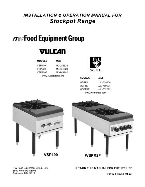
INSTALLATION & OPERATION MANUAL FOR<br />
Stockpot Range<br />
MODELS<br />
MLS<br />
VSP100 ML-052822<br />
VSP200 ML-052823<br />
VSP200F ML-769292<br />
www.vulcanhart.com<br />
MODELS<br />
MLS<br />
WSPR1 ML-760600<br />
WSPR2 ML-760601<br />
WSPR2F ML-769292<br />
www.wolfrange.com<br />
VSP100<br />
WSPR2F<br />
ITW Food Equipment Group, LLC<br />
3600 North Point Blvd.<br />
Baltimore, MD 21222<br />
RETAIN THIS MANUAL FOR FUTURE USE<br />
FORM F-36951 (04-07)
IMPORTANT FOR YOUR SAFETY<br />
THIS MANUAL HAS BEEN PREPARED FOR PERSONNEL QUALIFIED TO<br />
INSTALL GAS EQUIPMENT, WHO SHOULD PERFORM THE INITIAL FIELD<br />
START-UP AND ADJUSTMENTS OF THE EQUIPMENT COVERED BY THIS<br />
MANUAL.<br />
POST IN A PROMINENT LOCATION THE INSTRUCTIONS TO BE FOLLOWED IN<br />
THE EVENT THE SMELL OF GAS IS DETECTED. THIS INFORMATION CAN BE<br />
OBTAINED FROM THE LOCAL GAS SUPPLIER.<br />
IMPORTANT<br />
IN THE EVENT A GAS ODOR IS DETECTED, SHUT<br />
DOWN UNITS AT MAIN SHUTOFF VALVE AND<br />
CONTACT THE LOCAL GAS COMPANY OR GAS<br />
SUPPLIER FOR SERVICE.<br />
FOR YOUR SAFETY<br />
DO NOT STORE OR USE GASOLINE OR OTHER<br />
FLAMMABLE VAPORS OR LIQUIDS IN THE VICINITY OF<br />
THIS OR ANY OTHER APPLIANCE.<br />
WARNING: IMPROPER INSTALLATION, ADJUSTMENT,<br />
ALTERATION, SERVICE OR MAINTENANCE CAN<br />
CAUSE PROPERTY DAMAGE, INJURY OR DEATH.<br />
READ THE INSTALLATION, OPERATING AND<br />
MAINTENANCE INSTRUCTIONS THOROUGHLY BEFORE<br />
INSTALLING OR SERVICING THIS EQUIPMENT.<br />
IN THE EVENT OF A POWER FAILURE, DO NOT<br />
ATTEMPT TO OPERATE THIS DEVICE.<br />
- 2 -
INSTALLATION, OPERATION AND CARE OF<br />
STOCKPOT RANGE<br />
GENERAL<br />
Stockpot ranges are designed for commercial use only <strong>and</strong> feature fast, efficient gas<br />
heat. Each burner is controlled by an adjustable gas valve. Heavy-duty, cast iron top<br />
grate(s) are easily removed for cleaning when cool. A grease drawer is provided to collect<br />
fat run-off; it opens to the front for inspection or drain-off.<br />
Model Number of Burners BTU/hr Input Rating<br />
VSP100, WSPR1 2 110,000<br />
VSP200, WSPR2 4 220,000<br />
VSP200F, WSPR2F 4 220,000<br />
UNPACKING<br />
INSTALLATION<br />
Immediately after unpacking, check for possible shipping damage. If the stockpot is<br />
found to be damaged, save the packaging material <strong>and</strong> contact the carrier within 15 days<br />
of delivery.<br />
Before installing, verify that the type of gas (natural or propane) <strong>and</strong> the clearance<br />
dimensions (see below) agree with the specifications on the rating plate which is located<br />
at the back of the stockpot.<br />
LOCATION<br />
The installation location must be kept free <strong>and</strong> clear of combustibles. Do not obstruct the<br />
flow of combustion <strong>and</strong> ventilation air. DO NOT install the stockpot adjacent to open<br />
burners or fryers.<br />
Sufficient air should be allowed to enter the room to compensate for the amount of air<br />
removed by any ventilating system <strong>and</strong> for combustion of the gas burners. Do not<br />
obstruct the air flow into <strong>and</strong> around the appliance. Do not obstruct the flow of flue gases<br />
through <strong>and</strong> above the stockpot top grate. Position the stockpot in its final location.<br />
Check that there are sufficient clearances to service the stockpot <strong>and</strong> to make the<br />
required gas supply connection(s). Provide 24" clearance at the front for cleaning,<br />
maintenance, service <strong>and</strong> proper operation.<br />
Minimum Clearance Combustible Construction Non-Combustible Construction<br />
Rear 24” 4”<br />
Sides 18” 0”<br />
- 3 -
INSTALLATION CODES AND STANDARDS<br />
The Stockpot Range must be installed in accordance with:<br />
In the United States of America:<br />
1. State <strong>and</strong> local codes.<br />
2. National Fuel Gas Code, ANSI-Z223.1/NFPA #54 (latest edition). This shall include but<br />
not be limited to: NFPA #54 Section 10.3.5.2 for Venting. Copies may be obtained<br />
from The American Gas Association Accredited St<strong>and</strong>ards Committee Z223, @ 400<br />
N. Capital St. NW, Washington, DC 20001 or the Secretary St<strong>and</strong>ards Council, NFPA,<br />
1 Batterymarch Park Quincy, MA 02169-7471<br />
NOTE: In the Commonwealth of Massachusetts<br />
All gas appliances vented through a ventilation hood or exhaust system equipped with<br />
a damper or with a power means of exhaust shall comply with 248 CMR.<br />
3. NFPA St<strong>and</strong>ard # 96 Vapor Removal from Cooking Equipment, latest edition, available<br />
from the National Fire Protection Association, Batterymarch Park, Quincy, MA 02269.<br />
In Canada:<br />
1. Local codes.<br />
2. CAN/CSA-B149.1 Natural Gas <strong>Installation</strong> (latest edition)<br />
3. CAN/CSA-B149.2 Propane <strong>Installation</strong> Code (latest edition), available from the<br />
Canadian Gas Association, 178 Rexdale Blvd., Etobicoke, Ontario, Canada M9W<br />
1R3<br />
GAS PRESSURE REGULATOR INSTALLATION<br />
Gas regulator pressure is preset at 5” Water Column (W.C.) for natural gas, <strong>and</strong> 10” W.C.<br />
for propane gas. Minor adjustments may be required based on site specific gas pressure.<br />
Install the regulator as close to the stockpot on the gas supply line as possible. Make<br />
sure that the arrow on the underside of the regulator is oriented in the direction of gas<br />
flow to the stockpot (Fig. 2) <strong>and</strong> the regulator is positioned with the vent plug <strong>and</strong><br />
adjustment screw upright (Fig. 3).<br />
Fig. 2 Fig. 3<br />
The minimum supply pressure (upstream of the regulator) should be 7-9” W.C. for natural<br />
gas <strong>and</strong> 11-12” W.C. for propane gas. At no time should the hotplate be connected to<br />
supply pressure greater than ½ psig (3.45 kPa) or 14” W.C.<br />
- 4 -
LEVELING<br />
The Stockpot Range is equipped with legs. Turn the feet at the bottom of the legs in or<br />
out to level the Stockpot Range in the final installed location.<br />
VENTILATION HOOD<br />
The stockpot should be installed under a suitable ventilation hood. For safe operation <strong>and</strong><br />
proper ventilation, keep the space between the stockpot <strong>and</strong> vent hood free from any<br />
obstructions.<br />
GAS CONNECTION<br />
The data plate on the lower right side of the charbroiler indicates the type of gas your unit<br />
is equipped to burn. DO NOT connect to any other gas type.<br />
CAUTION: All gas supply connections <strong>and</strong> any pipe joint compound must be<br />
resistant to the action of propane.<br />
Purge the supply line to clean out any dust, dirt, or any foreign matter before connecting<br />
the line to the unit.<br />
Codes require that a gas shut-off valve be installed in the gas line ahead of the<br />
charbroiler. The gas supply line must be at least the equivalent of ¾” iron pipe. 72-inch<br />
units should be connected to the gas supply on both the left <strong>and</strong> right sides to provide<br />
adequate gas flow.<br />
A pressure regulator is supplied <strong>and</strong> must be installed outside of the broiler when making<br />
the gas supply connection. St<strong>and</strong>ard orifices are set for 5"WC (Water Column) for<br />
Natural Gas — 10"WC (Water Column) for Propane. Use the 1 / 8 ” pipe tap on the burner<br />
manifold for checking pressure. Make sure the gas piping is clean <strong>and</strong> free of<br />
obstructions, dirt, <strong>and</strong> piping compound.<br />
An adequate gas supply is necessary. Undersized or low pressure lines will restrict the<br />
volume of gas required for satisfactory performance. A maximum supply pressure of 7"<br />
W.C. for natural gas <strong>and</strong> 11" W.C. for propane gas is recommended. With all units<br />
operating simultaneously, the manifold pressure on all units should not show any<br />
appreciable drop.<br />
When testing the gas supply piping system, if test pressures exceed ½ psig (3.45 kPa),<br />
the charbroiler <strong>and</strong> its individual shutoff valve must be disconnected from the gas supply<br />
piping system. When test pressures are ½ psig (3.45 kPa) or less, the charbroiler must<br />
be isolated from the gas supply piping system by closing its individual manual shut-off<br />
valve during any pressure testing of the system.<br />
WARNING: PRIOR TO LIGHTING, CHECK ALL JOINTS IN THE GAS SUPPLY LINE FOR<br />
LEAKS. USE SOAP AND WATER SOLUTION. DO NOT USE AN OPEN FLAME.<br />
- 5 -
OPERATION<br />
WARNING: THE STOCKPOT RANGE AND ITS PARTS ARE HOT. BE CAREFUL WHEN<br />
OPERATING, CLEANING OR SERVICING THE STOCKPOT RANGE.<br />
CONTROLS<br />
The burner is in two sections, controlled by two heavy duty infinite control valves. The<br />
center “Star” section (Fig. 2) is on separate burner with an input of 55,000 BTU/hr. It is<br />
controlled by the right burner valve knob. The outer circle of the burner (Fig. 2) is the<br />
other separate 55,000 BTU/hr input burner, controlled by the left burner valve knob.<br />
These two separate burners provide heat flexibility. With one burner off <strong>and</strong> the second<br />
burner set low, up to both burners full on, you can move from low simmer on up to<br />
110,000 BTU/hr input.<br />
PILOT VALVE<br />
SCREW<br />
INNER<br />
BURNER<br />
OUTER<br />
BURNER<br />
Fig. 1 Fig 2.<br />
LIGHTING INSTRUCTIONS<br />
1. Turn all burner valves to OFF position <strong>and</strong> wait 5 minutes.<br />
2. Turn gas shutoff valve ON.<br />
3. Light st<strong>and</strong>ing pilot with a lit taper. Adjust pilot to ¼” high flame, if necessary, by<br />
turning pilot valve adjusting screw (see Fig. 1) counterclockwise to increase or<br />
clockwise to decrease flame.<br />
4. Turn burner valve to ON position.<br />
5. If pilot does not light, turn main gas supply OFF <strong>and</strong> repeat steps 1 through 4.<br />
TO COMPLETELY SHUTDOWN THE BURNERS AND PILOT LIGHTS<br />
For complete shutdown: Turn the main gas supply valve OFF.<br />
- 6 -
CLEANING<br />
Top grate(s) may be immersed in strong commercial cleaning compound overnight. In the<br />
morning, rinse with hot water to remove any residues of cleaning compound.<br />
Stainless steel surfaces may be cleaned using damp cloth with mild detergent <strong>and</strong> water<br />
solution.<br />
Places where fat, grease, or food can accumulate must be cleaned regularly.<br />
MAINTENANCE<br />
WARNING: THE STOCKPOT RANGE AND ITS PARTS ARE HOT. USE CARE WHEN<br />
OPERATING, CLEANING, OR SERVICING.<br />
SERVICE<br />
Contact your local Service Agency for any repairs or adjustments needed on this<br />
equipment.<br />
TROUBLESHOOTING<br />
Pilot Outage<br />
PROBLEM<br />
Improper burner<br />
combustion<br />
Poor Ignition<br />
1. Pilot flame too low<br />
2. Restriction in pilot orifice<br />
3. Restriction in pilot valve<br />
Improper ventilation<br />
POSSIBLE CAUSES<br />
1. Insufficient gas input<br />
2. Poor air-gas adjustment<br />
3. Restriction in pilot orifice<br />
4. Restriction in main burner ignition port<br />
5. Restriction in control valve<br />
6. Restriction in gas orifice<br />
- 7 -