Matrix210 Full Reference Manual.pdf - Datasensor
Matrix210 Full Reference Manual.pdf - Datasensor
Matrix210 Full Reference Manual.pdf - Datasensor

Create successful ePaper yourself
Turn your PDF publications into a flip-book with our unique Google optimized e-Paper software.
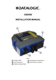
MATRIX 210<br />
<strong>Reference</strong> <strong>Manual</strong>
Datalogic Automation S.r.l.<br />
Via Lavino, 265<br />
40050 - Monte S. Pietro<br />
Bologna - Italy<br />
Matrix 210 <strong>Reference</strong> <strong>Manual</strong><br />
Ed.: 04/2011<br />
© 2011 Datalogic Automation S.r.l. • ALL RIGHTS RESERVED. • Protected to the fullest extent under<br />
U.S. and international laws. Copying, or altering of this document is prohibited without express written<br />
consent from Datalogic Automation S.r.l.<br />
Datalogic and the Datalogic logo are registered trademarks of Datalogic S.p.A. in many countries,<br />
including the U.S.A. and the E.U.<br />
Matrix 210, ID-NET, VisiSet and X-PRESS are trademarks of Datalogic Automation S.r.l. All other<br />
brand and product names mentioned herein are for identification purposes only and may be<br />
trademarks or registered trademarks of their respective owners.<br />
Datalogic shall not be liable for technical or editorial errors or omissions contained herein, nor for<br />
incidental or consequential damages resulting from the use of this material.<br />
21/04/11
CONTENTS<br />
REFERENCES ............................................................................................................vi<br />
Conventions................................................................................................................. vi<br />
<strong>Reference</strong> Documentation ........................................................................................... vi<br />
Service and Support .................................................................................................... vi<br />
Patents......................................................................................................................... vi<br />
COMPLIANCE............................................................................................................vii<br />
EMC Compliance.........................................................................................................vii<br />
Power Supply...............................................................................................................vii<br />
LED Class....................................................................................................................vii<br />
CE Compliance............................................................................................................vii<br />
FCC Compliance .........................................................................................................vii<br />
HANDLING................................................................................................................viii<br />
GENERAL VIEW ..........................................................................................................x<br />
1 RAPID CONFIGURATION ...........................................................................................1<br />
Step 1 – Connect the System .......................................................................................1<br />
Step 2 – Mount and Position the Reader......................................................................6<br />
Step 3 – Aim the Reader ..............................................................................................7<br />
Step 4 – X-PRESS Configuration..............................................................................8<br />
Reset Reader to Factory Default (Optional) .................................................................9<br />
Step 5 – Installing VisiSet Configuration Program ..................................................10<br />
Step 6 – Configuration Using Setup Wizard ...............................................................11<br />
Step 7 – Test Mode ....................................................................................................14<br />
Advanced Reader Configuration.................................................................................15<br />
2 INTRODUCTION ........................................................................................................16<br />
2.1 Product Description ....................................................................................................16<br />
2.2 Indicators and Keypad Button.....................................................................................19<br />
2.3 ID-NET ....................................................................................................................20<br />
2.3.1 How To Setup/Configure the Reader Network ...........................................................21<br />
2.3.2 ID-NET Slave Management Through Master..........................................................23<br />
2.4 CBX Backup and Restore Through VisiSet.............................................................24<br />
2.5 X-PRESS Human Machine Interface ......................................................................29<br />
2.5.1 X-PRESS Functions................................................................................................29<br />
2.6 Model Description .......................................................................................................31<br />
2.7 Accessories ................................................................................................................32<br />
2.8 Application Examples .................................................................................................32<br />
3 INSTALLATION .........................................................................................................35<br />
3.1 Package Contents ......................................................................................................35<br />
3.2 Mechanical Dimensions..............................................................................................36<br />
3.3 Mounting and Positioning Matrix 210 ......................................................................38<br />
4 CBX ELECTRICAL CONNECTIONS.........................................................................40<br />
4.1 Power Supply..............................................................................................................41<br />
4.2 Main Serial Interface...................................................................................................41<br />
4.2.1 RS232 Interface..........................................................................................................42<br />
4.2.2 RS485 <strong>Full</strong>-Duplex Interface.......................................................................................43<br />
4.2.3 RS485 Half-Duplex Interface ......................................................................................44<br />
iii
4.3 ID-NET Interface .....................................................................................................46<br />
4.3.1 ID-NET Cables ........................................................................................................46<br />
4.3.2 ID-NET Response Time ..........................................................................................47<br />
4.3.3 ID-NET Network Termination ..................................................................................51<br />
4.4 Auxiliary RS232 Interface ...........................................................................................51<br />
4.5 Inputs..........................................................................................................................52<br />
4.6 Outputs .......................................................................................................................55<br />
4.7 User Interface - Host...................................................................................................57<br />
5 25-PIN CABLE ELECTRICAL CONNECTIONS........................................................58<br />
5.1 25-Pin Connector........................................................................................................58<br />
5.2 M12-D 4-Pin Connector (Ethernet) .............................................................................59<br />
5.3 Power Supply..............................................................................................................60<br />
5.4 Main Serial Interface...................................................................................................60<br />
5.4.1 RS232 Interface..........................................................................................................61<br />
5.4.2 RS485 <strong>Full</strong>-Duplex Interface.......................................................................................62<br />
5.4.3 RS485 Half-Duplex Interface ......................................................................................63<br />
5.5 ID-NET Interface .....................................................................................................65<br />
5.5.1 ID-NET Cables ........................................................................................................65<br />
5.5.2 ID-NET Response Time ..........................................................................................66<br />
5.5.3 ID-NET Network Termination ..................................................................................70<br />
5.6 Auxiliary RS232 Interface ...........................................................................................70<br />
5.7 Ethernet Interface (Matrix 210 21x-x1x models only) .................................................71<br />
5.8 Inputs..........................................................................................................................72<br />
5.9 Outputs .......................................................................................................................75<br />
5.10 User Interface .............................................................................................................77<br />
6 TYPICAL LAYOUTS ..................................................................................................78<br />
6.1 Point-to-Point ..............................................................................................................78<br />
6.2 Pass-Through .............................................................................................................81<br />
6.2.1 Pass-Through on RS232 ............................................................................................81<br />
6.2.2 Pass-Through on ID-NET........................................................................................82<br />
6.3 ID-NET ....................................................................................................................83<br />
6.4 RS232 Master/Slave...................................................................................................89<br />
6.5 Multiplexer ..................................................................................................................90<br />
6.6 Ethernet Connection ...................................................................................................91<br />
6.7 USB Connection .........................................................................................................93<br />
7 READING FEATURES...............................................................................................94<br />
7.1 Maximum Line Speed Calculation ..............................................................................95<br />
8 SOFTWARE CONFIGURATION................................................................................97<br />
8.1 VisiSet System Requirements.................................................................................97<br />
8.2 Installing VisiSet......................................................................................................97<br />
8.3 Startup ........................................................................................................................98<br />
8.3.1 VisiSet Options........................................................................................................99<br />
8.4 Configuration ............................................................................................................101<br />
8.4.1 Edit Reader Parameters ...........................................................................................102<br />
8.4.2 Send Configuration Options......................................................................................104<br />
8.4.3 Calibration.................................................................................................................108<br />
8.4.4 Multi Image Acquisition Settings...............................................................................112<br />
8.4.5 Run Time Self Tuning (RTST) ..................................................................................112<br />
8.4.6 Region Of Interest Windowing ..................................................................................113<br />
8.4.7 Direct Part Marking Applications...............................................................................114<br />
8.5 Image Capture and Decoding...................................................................................116<br />
iv
8.6 Statistics ...................................................................................................................116<br />
9 MAINTENANCE .......................................................................................................117<br />
9.1 Cleaning....................................................................................................................117<br />
10 TROUBLESHOOTING .............................................................................................118<br />
10.1 General Guidelines ...................................................................................................118<br />
11 TECHNICAL FEATURES.........................................................................................121<br />
GLOSSARY..............................................................................................................123<br />
INDEX.......................................................................................................................126<br />
v
REFERENCES<br />
CONVENTIONS<br />
This manual uses the following conventions:<br />
"User" refers to anyone using a Matrix 210 reader.<br />
"Reader" refers to the Matrix 210 reader.<br />
"You" refers to the System Administrator or Technical Support person using this manual to<br />
install, configure, operate, maintain or troubleshoot a Matrix 210 reader.<br />
REFERENCE DOCUMENTATION<br />
For further details refer to: the VisiSet Help On Line, Matrix Reading Methods, Matrix Host<br />
Mode Programming, Matrix SW Parameter Guide, Matrix Code Quality Verifier Solution<br />
provided as supplementary documentation on Mini-DVD.<br />
SERVICE AND SUPPORT<br />
Datalogic provides several services as well as technical support through its website. Log on<br />
to www.automation.datalogic.com and click on the links indicated for further information:<br />
<br />
<br />
PRODUCTS<br />
Search through the links to arrive at your product page which describes specific Info,<br />
Features, Applications, Models, Accessories, and Downloads including the VisiSet<br />
utility program, which allows device configuration using a PC. It provides RS232 and<br />
Ethernet interface configuration.<br />
SERVICE<br />
- Overview - Warranty Extensions and Maintenance Agreements<br />
- Sales Network- Listing of Subsidiaries, Repair Centers, Partners<br />
- Helpdesk<br />
- Material Return Authorization<br />
PATENTS<br />
This product is covered by one or more of the following patents:<br />
U.S. patents: 6,512,218 B1; 6,616,039 B1; 6,808,114 B1; 6,997,385 B2; 7,102,116 B2;<br />
7,282,688 B2<br />
European patents: 999,514 B1; 1,014,292 B1; 1,128,315 B1.<br />
Additional patents pending.<br />
vi
COMPLIANCE<br />
For installation, use and maintenance it is not necessary to open the reader.<br />
Only connect Ethernet and dataport connections to a network which has routing only within<br />
the plant or building and no routing outside the plant or building.<br />
EMC COMPLIANCE<br />
In order to meet the EMC requirements:<br />
connect reader chassis to the plant earth ground by means of a flat copper braid shorter<br />
than 100 mm;<br />
for CBX connections, connect the pin "Earth" to a good Earth Ground;<br />
for direct connections, connect the main interface cable shield to pin 1 of the 25-pin<br />
connector.<br />
POWER SUPPLY<br />
ATTENTION: READ THIS INFORMATION BEFORE INSTALLING THE PRODUCT<br />
This product is intended to be installed by Qualified Personnel only.<br />
This product is intended to be connected to a UL Listed Computer which supplies power<br />
directly to the reader or a UL Listed Direct Plug-in Power Unit marked LPS or “Class 2”, rated<br />
10 to 30 V, minimum 500 mA.<br />
LED CLASS<br />
Class 1 LED Product to EN60825-1:2001<br />
CE COMPLIANCE<br />
Warning: This is a Class A product. In a domestic environment this product may cause radio<br />
interference in which case the user may be required to take adequate measures.<br />
FCC COMPLIANCE<br />
Modifications or changes to this equipment without the expressed written approval of Datalogic could void the<br />
authority to use the equipment.<br />
This device complies with PART 15 of the FCC Rules. Operation is subject to the following two conditions: (1)<br />
This device may not cause harmful interference, and (2) this device must accept any interference received,<br />
including interference which may cause undesired operation.<br />
This equipment has been tested and found to comply with the limits for a Class A digital device, pursuant to part<br />
15 of the FCC Rules. These limits are designed to provide reasonable protection against harmful interference<br />
when the equipment is operated in a commercial environment. This equipment generates, uses, and can radiate<br />
radio frequency energy and, if not installed and used in accordance with the instruction manual, may cause<br />
harmful interference to radio communications. Operation of this equipment in a residential area is likely to cause<br />
harmful interference in which case the user will be required to correct the interference at his own expense.<br />
vii
HANDLING<br />
The Matrix 210 is designed to be used in an industrial environment and is built to withstand<br />
vibration and shock when correctly installed, however it is also a precision product and<br />
therefore before and during installation it must be handled correctly to avoid damage.<br />
<br />
avoid that the readers are dropped (exceeding shock limits).<br />
<br />
do not fine tune the positioning by striking the reader or bracket.<br />
viii
do not weld the reader into position which can cause electrostatic, heat or reading<br />
window damage.<br />
<br />
do not spray paint near the reader which can cause reading window damage.<br />
ix
GENERAL VIEW<br />
Matrix 210<br />
2<br />
3<br />
4<br />
6<br />
5<br />
1<br />
1<br />
Figure A<br />
1 Mounting Holes (4) 3<br />
Ethernet Network Presence<br />
LED (for Ethernet Models)<br />
2 "Power ON" LED<br />
4 HMI X-PRESS Interface<br />
5<br />
6<br />
Reading Window<br />
Device Class Labels<br />
x
RAPID CONFIGURATION<br />
1<br />
1 RAPID CONFIGURATION<br />
STEP 1 – CONNECT THE SYSTEM<br />
25-Pin Models<br />
To connect the system in a Stand Alone configuration, you need the hardware indicated in<br />
Figure 1. In this layout the data is transmitted to the Host on the main serial interface. Data<br />
can also be transmitted on the RS232 auxiliary interface independently from the main<br />
interface selection.<br />
When One Shot or Phase Mode Operating mode is used, the reader is activated by an<br />
External Trigger (photoelectric sensor) when the object enters its reading zone.<br />
PG 6000<br />
CBX<br />
Main Interface<br />
Matrix 210<br />
Host<br />
P.S.*<br />
I/O, AUX<br />
* External Trigger or Presence Sensor<br />
(for One Shot or Phase Mode)<br />
Figure 1 – Matrix 210 in Stand Alone Layout<br />
1
1<br />
MATRIX 210 REFERENCE MANUAL<br />
CBX100/CBX500 Pinout for Matrix 210 25-Pin Models<br />
The table below gives the pinout of the CBX100/CBX500 terminal block connectors. Use this<br />
pinout when the Matrix 210 reader is connected by means of the CBX100/CBX500:<br />
CBX100/500 Terminal Block Connectors<br />
Input Power<br />
Outputs<br />
Vdc Power Supply Input Voltage + +V Power Source - Outputs<br />
GND Power Supply Input Voltage - -V Power <strong>Reference</strong> - Outputs<br />
Earth Protection Earth Ground O1+ Output 1 +<br />
O1- Output 1 -<br />
Inputs O2+ Output 2 +<br />
+V Power Source – External Trigger O2- Output 2 -<br />
I1A External Trigger A (polarity insensitive) Auxiliary Interface<br />
I1B External Trigger B (polarity insensitive) TX Auxiliary Interface TX<br />
-V Power <strong>Reference</strong> – External Trigger RX Auxiliary Interface RX<br />
+V Power Source – Inputs SGND Auxiliary Interface <strong>Reference</strong><br />
I2A Input 2 A (polarity insensitive) ID-NET<br />
I2B Input 2 B (polarity insensitive) REF Network <strong>Reference</strong><br />
-V Power <strong>Reference</strong> – Inputs ID+ ID-NET network +<br />
Shield ID- ID-NET network -<br />
Shield Network Cable Shield<br />
Main Interface<br />
RS232 RS485 <strong>Full</strong>-Duplex RS485 Half-Duplex<br />
TX TX+ RTX+<br />
RTS TX- RTX-<br />
RX<br />
*RX+<br />
CTS<br />
*RX-<br />
SGND SGND SGND<br />
* Do not leave floating, see par. 4.2.2 for connection details.<br />
CAUTION<br />
Do not connect GND, SGND and REF to different (external) ground<br />
references. GND, SGND and REF are internally connected through filtering<br />
circuitry which can be permanently damaged if subjected to voltage drops<br />
over 0.8 Vdc.<br />
2
RAPID CONFIGURATION<br />
1<br />
25-Pin Connector Pinout for Matrix 210 25-Pin Models<br />
The table below gives the pinout of the 25-pin male D-sub connector for connection to the<br />
power supply and input/output signals. Use this pinout when the Matrix 210 reader is<br />
connected by means of the 25-pin connector:<br />
1<br />
13<br />
14<br />
25<br />
Figure 2 - 25-pin Male D-sub Connector<br />
25-pin D-sub male connector pinout<br />
Pin Name Function<br />
13, 9 Vdc Power supply input voltage +<br />
25, 7 GND Power supply input voltage -<br />
1 CHASSIS Cable shield connected to chassis<br />
18 I1A External Trigger A (polarity insensitive)<br />
19 I1B External Trigger B (polarity insensitive)<br />
6 I2A Input 2 A (polarity insensitive)<br />
10 I2B Input 2 B (polarity insensitive)<br />
8 O1+ Output 1 +<br />
22 O1- Output 1 -<br />
11 O2+ Output 2 +<br />
12 O2- Output 2 -<br />
20 RX Auxiliary RS232 RX<br />
21 TX Auxiliary RS232 TX<br />
23 ID+ ID-NET network +<br />
24 ID- ID-NET network -<br />
14, 15, 16, 17 NC Not Connected<br />
Pin Name RS232<br />
RS485<br />
RS485<br />
<strong>Full</strong>-Duplex Half-Duplex<br />
2 TX TX+ RTX+<br />
3 MAIN INTERFACE RX *RX+<br />
4 (SW SELECTABLE) RTS TX- RTX-<br />
5<br />
CTS<br />
*RX-<br />
* Do not leave floating, see par. 5.4.2 for connection details.<br />
3
1<br />
MATRIX 210 REFERENCE MANUAL<br />
USB Models<br />
NOTE<br />
Before connecting the reader to the USB Port, Install the USB Virtual COM<br />
Port Driver from the Support Files\USB Virtual COM Port Drivers directory<br />
on the VisiSet Mini-DVD.<br />
The USB Virtual COM Port Driver allows sending serial data using the Matrix 210 USB<br />
port. A different virtual COM Port will be assigned to each connected reader.<br />
Installing the USB Virtual COM port drivers:<br />
1. Double-click on the following file to launch the USB Virtual COM Port Driver Installer.<br />
Windows XP/Vista/7 (x32) = "DPInst.exe"<br />
Windows Vista/7 (x64) = "DPInst64.exe"<br />
For other operating systems see the readme txt in the Support Files\USB Virtual COM Port<br />
Drivers directory. For updated drivers or more details go to ftdichip.com/Drivers/VCP.htm.<br />
Configuring the USB Virtual COM port:<br />
Connect the Matrix 210 USB reader to your PC; a new virtual COM port is associated with<br />
the reader. Follow these steps to configure the associated COM Port:<br />
2. Right-click on "My Computer" in the Windows "Start" menu and select "Properties".<br />
3. Select the "Hardware" tab in the System Properties dialog and click the "Device<br />
Manager" button.<br />
4. Expand the "Ports (COM & LPT)" item on the "Device Manager" menu. Right-click on<br />
"USB Serial Port" and select "Properties".<br />
5. Select the "Port Settings" tab in the "Properties" dialog and click the "Advanced" button.<br />
4
RAPID CONFIGURATION<br />
1<br />
6. From the "Advanced Settings for COMx" dialog:<br />
<br />
Expand the "COM Port Number" menu and select a new COM Port number if<br />
desired (optional).<br />
Set the "BM Options" -> "Latency Timer" (msec) parameter to 1.<br />
You are now ready to use the new COM Port.<br />
Matrix 210 USB models can be connected in a Point-to-Point layout to a local host through<br />
their USB cable. No external power supply is necessary.<br />
Matrix 210<br />
Host<br />
Figure 3 – Matrix 210 USB Model in a Point-to-Point Layout<br />
5
1<br />
MATRIX 210 REFERENCE MANUAL<br />
STEP 2 – MOUNT AND POSITION THE READER<br />
1. To mount the Matrix 210, use the mounting brackets to obtain the most suitable<br />
position for the reader. Two of the most common mounting configurations are shown in<br />
the figures below. Other mounting solutions are provided in par. 3.3.<br />
Tilt<br />
Pitch<br />
Figure 4 –Positioning 90° Model with Mounting Bracket<br />
Tilt<br />
Pitch<br />
Figure 5 –Positioning Straight Model with Mounting Bracket<br />
2. When mounting the Matrix 210 take into consideration these three ideal label position<br />
angles: Pitch or Skew 10° to 20° and Tilt 0°, although the reader can read a code at any tilt<br />
angle.<br />
P<br />
S<br />
T<br />
Assure at least 10° Minimize Minimize<br />
Figure 6 – Pitch, Skew and Tilt Angles<br />
6
RAPID CONFIGURATION<br />
1<br />
3. Refer to the Reading Features table in chp. 7 to determine the distance your reader<br />
should be positioned at.<br />
NOTE<br />
Rapid Configuration of the Matrix 210 reader can be made either through<br />
the X-PRESS interface (steps 3-4) which requires no PC connection, or<br />
by using the VisiSet Setup Wizard (steps 5-6). Select the procedure<br />
according to your needs.<br />
STEP 3 – AIM THE READER<br />
Matrix 210 provides a built-in aiming system to aid reader positioning. The aiming system<br />
is accessed through the X-PRESS Interface.<br />
1. Power the reader on. During the reader startup (reset or restart phase), all the LEDs blink<br />
for one second. On the connector side of the reader near the cable, the “POWER ON”<br />
LED (blue) indicates the reader is correctly powered.<br />
2. Enter the Aim/Locate function by pressing and holding the X-PRESS push button until<br />
the Aim LED is on.<br />
3. Release the button to enter the Aim function. The aiming system turns on see Figure 7.<br />
4. Place the application specific code in front of the reader at the reading distance indicated<br />
for your model in the Reading Features table, centering it in the aiming system indicator.<br />
default value for:<br />
NEAR, MEDIUM,<br />
FAR models<br />
FOV<br />
green<br />
green<br />
default value for:<br />
UHD models<br />
FOV<br />
yellow<br />
yellow<br />
red<br />
Figure 7 – Aiming Function Using The Blue Ring or<br />
Internal Lighting System *<br />
Figure 8 – X-PRESS Interface: Aim Function<br />
* the default value of the Aiming System Status parameter can be changed in VisiSet.<br />
5. Exit the Aim function by pressing the X-PRESS push button once. The aiming system<br />
turns off.<br />
7
1<br />
MATRIX 210 REFERENCE MANUAL<br />
STEP 4 – X-PRESS CONFIGURATION<br />
Once Matrix 210 is positioned with respect to the code (step 3), you can configure it for<br />
optimal code reading relative to your application. This configuration can be performed either<br />
through the X-PRESS Interface or the VisiSet configuration program.<br />
Setup<br />
1. Enter the Setup function by pressing and holding<br />
the X-PRESS push button until the Setup LED is<br />
on.<br />
2. Release the button to enter the Setup function.<br />
The Setup LED will blink until the procedure is<br />
completed.<br />
The Setup procedure ends when the Image<br />
Acquisition parameters are successfully saved in<br />
the reader memory, the Setup LED will remain on<br />
continuously and Matrix 210 emits 3 high pitched<br />
beeps.<br />
If the calibration cannot be reached after a timeout<br />
of about 5 (five) seconds Matrix 210 will exit<br />
without saving the parameters to memory, the<br />
Setup LED will not remain on continuously but it will<br />
just stop blinking. In this case Matrix 210 emits a<br />
long low pitched beep.<br />
3. Exit the Setup function by pressing the X-<br />
PRESS push button once.<br />
Learn<br />
4. Enter the Learn function by pressing and holding<br />
the X-PRESS push button until the Learn LED is<br />
on.<br />
5. Release the button to enter the Learn function.<br />
The Learn LED will blink until the procedure is<br />
completed.<br />
The Learn procedure ends when the Image<br />
Processing and Decoding parameters are<br />
successfully saved in the reader memory, the<br />
Learn LED will remain on continuously, the Green<br />
Spot is activated and Matrix 210 emits 3 high<br />
pitched beeps 1 .<br />
If the calibration cannot be reached after a timeout<br />
of about 3 (three) minutes Matrix 210 will exit<br />
without saving the parameters to memory, the<br />
Learn LED will not remain on continuously but it will<br />
just stop blinking. In this case Matrix 210 emits a<br />
long low pitched beep.<br />
6. Exit the Setup function by pressing the X-<br />
PRESS push button once.<br />
green<br />
green<br />
yellow<br />
yellow<br />
red<br />
Figure 9 – X-PRESS Interface: Setup<br />
Function<br />
green<br />
green<br />
yellow<br />
yellow<br />
red<br />
Figure 10 – X-PRESS Interface:<br />
Learn Function<br />
1 The Learn procedure will not recognize Pharmacode symbologies.<br />
8
RAPID CONFIGURATION<br />
1<br />
NOTE<br />
If you have used this procedure to configure Matrix 210 go to step 7.<br />
RESET READER TO FACTORY DEFAULT (OPTIONAL)<br />
If it ever becomes necessary to reset the reader to the factory default values, you can<br />
perform this procedure by holding the X-PRESS push button pressed while powering up<br />
the reader. You must keep the X-PRESS push button pressed until the power up<br />
sequence is completed (several seconds) and all LEDs blink simultaneously 3 times.<br />
All LEDs remain on for about 1 second, then off for one second, the Configuration and<br />
Environmental parameters are reset, and the status LED remains on. If connected through a<br />
CBX500 with display module, the message "Default Set" is shown on the display.<br />
9
1<br />
MATRIX 210 REFERENCE MANUAL<br />
STEP 5 – INSTALLING VISISET CONFIGURATION PROGRAM<br />
VisiSet is a Datalogic reader configuration tool providing several important advantages:<br />
<br />
<br />
<br />
Setup Wizard for rapid configuration and new users;<br />
Defined configuration directly stored in the reader;<br />
Communication protocol independent from the physical interface allowing to consider the<br />
reader as a remote object to be configured and monitored.<br />
To install VisiSet, turn on the PC that will be used for the configuration, running<br />
Windows 98, 2000/NT, XP, Vista or 7, then insert the VisiSet Mini-DVD, wait for the<br />
DVD to autorun and follow the installation procedure.<br />
This configuration procedure assumes a laptop computer, running VisiSet, is connected to<br />
the reader's auxiliary port.<br />
After installing and running the VisiSet software program the following window:<br />
Figure 11 - VisiSet Opening Window<br />
10
RAPID CONFIGURATION<br />
1<br />
Set the communication parameters from the "Options" menu. Then select "Connect", the<br />
following window appears:<br />
Figure 12 - VisiSet Main Window After Connection<br />
STEP 6 – CONFIGURATION USING SETUP WIZARD<br />
The Setup Wizard option is advised for rapid configuration or for new users. It allows reader<br />
configuration in a few easy steps.<br />
1. Select the Setup Wizard button from the Main menu.<br />
Place the application specific code in front of the reader at the correct reading distance<br />
(see step 2 and the Reading Features table in the chp. 7).<br />
11
1<br />
MATRIX 210 REFERENCE MANUAL<br />
2. Press the "Positioning" button. The reader continuously acquires images and gives visual<br />
feedback in the view image window. The Setup Wizard now shows four delimiters (red<br />
points) in the acquired images which indicate the region in which the calibration algorithm<br />
is active. Move the reader (or code) to center it.<br />
Press the Positioning button again to stop positioning.<br />
2<br />
3. Select a Calibration Mode choice and press the "Calibrate" button. The reader flashes<br />
once acquiring the image and auto determines the best exposure and gain settings. If the<br />
code symbology is enabled by default, the code will also be decoded.<br />
3<br />
12
RAPID CONFIGURATION<br />
1<br />
4. Select a Code Setting Mode choice and press the "Code Setting" button.<br />
The Setup Result section of the Setup Wizard window shows the code type results and<br />
the parameter settings.<br />
4<br />
Setup Result<br />
5. Select a Saving Options choice and press the "Save" button.<br />
6. Close the Setup Wizard.<br />
NOTE<br />
If your application has been configured using the VisiSet Setup Wizard,<br />
your reader is ready. If necessary you can use VisiSet for advanced<br />
reader configuration.<br />
13
1<br />
MATRIX 210 REFERENCE MANUAL<br />
STEP 7 – TEST MODE<br />
Use a code suitable to your application to test the reading performance of the system.<br />
Alternatively, you can use the Datalogic 1D/2D Test Chart (Code 39, Data Matrix ECC 200).<br />
1. Enter the Test function by pressing and holding the X-PRESS push button until the<br />
Test LED is on.<br />
2. Release the button to enter the Test function.<br />
Once entered, the Bar Graph on the five LEDs is activated and if the reader starts<br />
reading codes the Bar-Graph shows the Good Read Rate. In case of no read condition,<br />
only the STATUS LED is on and blinks.<br />
green<br />
green<br />
yellow<br />
yellow<br />
red<br />
Figure 13 – X-PRESS Interface: Test Function<br />
3. To exit the Test, press the X-PRESS push button once.<br />
NOTE<br />
By default, the Test exits automatically after three minutes.<br />
The Bar Graph has the following meaning:<br />
95%<br />
75%<br />
60%<br />
40%<br />
20%<br />
Figure 14 – Test Bar Graph<br />
14
RAPID CONFIGURATION<br />
1<br />
ADVANCED READER CONFIGURATION<br />
For further details on advanced product configuration, refer to the VisiSet Help On-Line.<br />
The following are alternative or advanced reader configuration methods:<br />
Advanced Configuration Using VisiSet<br />
Advanced configuration can be performed through the VisiSet program by selecting<br />
Device> Get Configuration From Temporary Memory to open the Parameter Setup window in<br />
off-line mode. Advanced configuration is addressed to expert users being able to complete a<br />
detailed reader configuration. The desired parameters can be defined in the various folders<br />
of the Parameter Setup window and then sent to the reader memory (either Temporary or<br />
Permanent):<br />
Figure 15 - VisiSet Parameter Setup Window<br />
Host Mode Programming<br />
The reader can also be configured from a host computer using the Host Mode programming<br />
procedure, by commands via the serial interface. See the Host Mode Programming file on<br />
the Mini-DVD.<br />
Alternative Layouts<br />
If you need to install an Ethernet network, ID-NET network, Fieldbus network, Pass-<br />
Through network, Multiplexer network or an RS232 Master/Slave refer to the Matrix 210<br />
<strong>Reference</strong> <strong>Manual</strong>.<br />
The reader can also be setup for alternative layouts by reading programming barcodes. See<br />
the "Setup Procedure Using Programming Barcodes" printable from the Mini-DVD.<br />
Code Quality Verification<br />
Matrix 210 can be used as a Code Quality Verifier according to the ISO/IEC 15415,<br />
ISO/IEC 15416, AS9132, and AIM DPM Standards.<br />
15
2<br />
MATRIX 210 REFERENCE MANUAL<br />
2 INTRODUCTION<br />
2.1 PRODUCT DESCRIPTION<br />
Matrix 210 is the new Datalogic 2D reader offering excellent reading performance, ultra<br />
compact size and extreme ease of use. Thanks to innovative optical features, advanced<br />
software functions and complete connectivity options, Matrix 210 is the cost effective<br />
solution for applications where the space is very limited.<br />
Ultra Compact Size<br />
Compact dimensions, straight and 90° reading window models availability allow flexible<br />
mounting and positioning in narrow spaces.<br />
Excellent Reading Performance<br />
WVGA image sensor, up to 60 frames/s acquisition rate and dynamic reading capability,<br />
together with powerful decoding libraries provide excellent performance on a wide range of<br />
code symbologies as well as damaged and low quality codes. Matrix 210 allows reading<br />
10 mils codes in moving applications at speeds up to 2 m/sec.<br />
Innovative Optical Features<br />
The innovative optical and lighting systems ensure wide field of view at short reading<br />
distances, combined with excellent illumination pattern. Matrix 210 has a maximum<br />
reading distance of 200 mm, and it can read at near distance ultra high density 2D codes up<br />
to 0.076 mm (3 mils).<br />
Ease Of Use<br />
The intuitive X-PRESS Human Machine Interface makes installation and maintenance<br />
easier than ever thanks to a five LED bar graph and the multi-function key providing<br />
immediate access to relevant functions such as Aiming, Setup (for automatic imager<br />
calibration), Learn (for automatic code setting), Test Mode (for bar graph activation). A Green<br />
Spot provides immediate Good Read feedback.<br />
Enhanced Connectivity<br />
An embedded high speed ID-NET communication interface allows efficient data collection<br />
and simplifies network wiring. USB interface models allow direct connection to a PC.<br />
Industrial Features<br />
Matrix 210, with its rugged construction, IP65 protection class, 50°C max operating<br />
temperature and 10 to 30 VDC power supply is the ideal product for industrial applications.<br />
16
INTRODUCTION<br />
2<br />
Matrix 210 has been developed for use in numerous industries like:<br />
Electronics:<br />
• PCB Board Tracking<br />
• Electronics Product Tracking<br />
Pharmaceutical & Chemical:<br />
• Medical Devices Traceability<br />
• Pharmaceutical and Medicine Manufacturing<br />
OEM:<br />
• Chemical & Biomedical Analysis Machines<br />
• Access Control Systems<br />
• Self Service Systems (ATM, Kiosks)<br />
• Print & Apply systems<br />
• Document Handling<br />
This technology intrinsically provides omni-directional reading.<br />
Standard Application Program<br />
A Standard Application Program is factory-loaded onto Matrix 210. This program controls<br />
code reading, data formatting, Ethernet interfacing, serial port and USB interfacing, and<br />
many other operating and control parameters. It is completely user configurable from a<br />
Laptop or PC using the dedicated configuration software program VisiSet, provided on<br />
Mini-DVD with the reader.<br />
There are different programmable operating modes to suit various code reading system<br />
requirements.<br />
Quick, automatic positioning, calibration and code setting of the imager can be accomplished<br />
using the X-PRESS button and LEDs on top of the reader without the necessity of a PC.<br />
The previous functions can also be performed through VisiSet through the Setup Wizard.<br />
This tool includes visual feedback from the reader.<br />
VisiSet provides a Calibration Tool to verify the exact positioning of the reader and to<br />
maximize its reading performance.<br />
Statistics on the reading performance can also be visualized through a dedicated window in<br />
VisiSet.<br />
Symbol Verification can be performed through VisiSet when the reader has been installed<br />
and setup as a Verifier station.<br />
Programmability<br />
If your requirements are not met by the Standard Application Program, Custom Application<br />
Programs can be requested at your local Datalogic distributor.<br />
17
2<br />
MATRIX 210 REFERENCE MANUAL<br />
Some of the main features of this reader are given below:<br />
Ultra Compact Dimensions<br />
Direct and 90° window models for smart mounting<br />
Outstanding decoding capability on 1D, 2D, Stacked and Postal symbologies<br />
High performance on dynamic reading applications<br />
X-PRESS for easy and intuitive setup<br />
Optical Aiming System<br />
10 to 30 VDC Power Supply<br />
High Speed Ethernet Connectivity<br />
USB Connectivity<br />
ID-NET embedded high speed connectivity<br />
Region Of Interest Windowing for higher frame rate<br />
Run Time Self Tuning for higher flexibility<br />
18
INTRODUCTION<br />
2<br />
2.2 INDICATORS AND KEYPAD BUTTON<br />
3<br />
4<br />
5<br />
6<br />
2<br />
7 8<br />
1<br />
Figure 16 - Indicators<br />
The following LED indicators are located on the reader:<br />
NET For Ethernet models, on the connector side of the reader near the Ethernet<br />
connector, the orange ETHERNET NETWORK PRESENCE LED indicates the<br />
on-board Ethernet network connection. (Figure 16, 1)<br />
PWR On the connector side of the reader near the cable, the blue POWER ON LED<br />
indicates the reader is correctly powered. (Figure 16, 2)<br />
In normal operating mode the colors and meaning of the five LEDs are illustrated in the<br />
following table:<br />
READY green LED indicates that the reader is ready to operate (Figure 16, 3)<br />
GOOD green LED confirms successful reading (Figure 16, 4)<br />
TRIGGER yellow LED indicates the status of the reading phase (Figure 16, 5)<br />
COM yellow LED indicates active communication on the main serial port * (Figure 16, 6)<br />
STATUS red LED indicates a NO READ result (Figure 16, 7)<br />
* When connected to a Fieldbus network through the CBX500, the COM LED is always active, even in the<br />
absence of data transmission, because of polling activity on the Fieldbus network.<br />
During the reader startup (reset or restart phase), these five LEDs blink for one second.<br />
In X-PRESS Configuration mode the colors and meaning of these five LEDs are described<br />
in par. 2.4.<br />
The keypad button (Figure 16, 8, is software programmable. By default it starts the X-<br />
PRESS interface for quick installation without using a PC (see chp. 1).<br />
19
2<br />
MATRIX 210 REFERENCE MANUAL<br />
2.3 ID-NET<br />
The ID-NET network is a built-in high-speed interface dedicated<br />
for high-speed reader interconnection. ID-NET is in addition to<br />
the Main and Auxiliary serial interfaces.<br />
The following network configurations are available:<br />
• ID-NET M/S Synchronized: Single station – multiple readers<br />
ID-NET interface allows local connection of multiple readers reading different sides of the<br />
same target. All readers share a single presence sensor and activate/deactivate<br />
simultaneously.<br />
At the end of each reading phase a single data message is transmitted to the host.<br />
Thanks to ID-NET, data communication among readers is highly efficient so that an<br />
immediate result will be available.<br />
20
INTRODUCTION<br />
2<br />
• ID-NET M/S Multidata: Multiple stations – single reader<br />
ID-NET interface allows connection of readers reading objects placed on independent<br />
conveyors. All readers are typically located far away from each other and they use a<br />
dedicated presence sensor.<br />
At the end of each reading phase, each reader transmits its own data message to the host.<br />
Thanks to ID-NET, data collection among readers is accomplished at a high speed without<br />
the need of an external multiplexing device. This leads to an overall cost reduction and to a<br />
simple system wiring.<br />
2.3.1 How To Setup/Configure the Reader Network<br />
A complete ID-NET reader network can be easily setup through VisiSet as follows:<br />
Mounting & Connection<br />
1. Mechanically mount/install all the readers (refer to par. 3.2 and 3.3).<br />
2. Wire ID-NET (refer to par. 4.3 or 5.5).<br />
3. Power up the entire system.<br />
Configuration of Slaves<br />
1. Connect a PC equipped with VisiSet to the Main, Auxiliary or Ethernet interface of the<br />
planned Slave reader.<br />
2. Launch VisiSet and connect to the Slave reader.<br />
3. From the VisiSet Device Menu select "Parameter Setup".<br />
4. Set the Role of the Slave reader (Synchronized or Multidata) from the<br />
Reading System Layout > Device Network Setting > Topology Role parameter.<br />
5. Set the Slave Address according to the desired value 1-31 from the<br />
Reading System Layout > Device Network Setting > Slave Address parameter. Each<br />
reader must have a different Address on the ID-NET Network.<br />
6. If necessary, set the ID-NET baudrate from the Reading System Layout ><br />
Device Network Setting > Network Baud Rate parameter, (500 kbs default).<br />
21
2<br />
MATRIX 210 REFERENCE MANUAL<br />
7. Configure the other device parameters via VisiSet [Operating Mode, Calibration, Data<br />
Collection parameters, etc.].<br />
8. The Slave device is now Configured. Physically connect it to the Master/Slave network. If<br />
using the CBX connection box equipped with a BM100 Backup module, you can perform<br />
Device Backup at the Slave (see par. 2.4 for details).<br />
Repeat these steps for each Slave reader in the ID-NET network.<br />
Configuration of Master<br />
1. Connect a PC equipped with VisiSet to the Main Auxiliary or Ethernet interface of the<br />
planned Master reader.<br />
2. Launch VisiSet and connect to the Master reader.<br />
3. From the VisiSet Device Menu select "Parameter Setup".<br />
4. Set the Role of the Master reader (Synchronized or Multidata) from the<br />
Reading System Layout > Device Network Setting > Topology Role parameter.<br />
5. Enable the planned Slave device N from the Reading System Layout ><br />
Expected Slave Device #N > Status parameter and, if desired, set the related<br />
identification string from the Expected Slave Device #N > Device Description parameter.<br />
Repeat this step for all planned Slave devices.<br />
6. If necessary, set the ID-NET baudrate from the Reading System Layout ><br />
Device Network Setting > Network Baud Rate parameter, (500 kbs default).<br />
7. Configure the other device parameters via VisiSet [Operating Mode, Calibration, Data<br />
Collection parameters, etc.].<br />
8. The Master device is now Configured. Physically connect it to the Master/Slave network.<br />
If using the CBX connection box equipped with a BM100 Backup module, perform a<br />
Network Backup at the Master (see par. 2.4 for details).<br />
9. From the VisiSet Device Menu select "ID-NET Status Window" and click on the<br />
"Look For Devices On Network" button to check the status of the expected Slave devices<br />
within the ID-NET network.<br />
The reader network is ready.<br />
22
INTRODUCTION<br />
2<br />
2.3.2 ID-NET Slave Management Through Master<br />
When an ID-NET layout has already been configured, it is possible to modify the<br />
configuration of any Slave from VisiSet through the Master.<br />
1. Connect a PC equipped with VisiSet to the Main, or Auxiliary interface of the Master<br />
reader.<br />
2. Launch VisiSet and connect to the Master reader.<br />
3. From the VisiSet Device Menu select "ID-NET Status Window" and click on the<br />
"Look For Devices On Network" button to check the status of the expected Slave devices<br />
within the ID-NET network.<br />
4. Click anywhere in the row of the specific slave in the ID-NET Status Window when its<br />
Current Status is "Present". The Parameter Setup window will be displayed after a time<br />
based on the network speed, with the configuration of the selected slave.<br />
5. From the specific Slave Parameter Setup Window, change any parameter (not in<br />
interactive mode), save the configuration to a file, or load a configuration from a file.<br />
6. Send the modified configuration to the slave.<br />
CAUTION<br />
If a wrong configuration is set or if the Slave Reading System Layout<br />
parameters are changed, the slave could lose the network connection.<br />
23
2<br />
MATRIX 210 REFERENCE MANUAL<br />
2.4 CBX BACKUP AND RESTORE THROUGH VISISET<br />
The "CBX Backup" or "CBX Restore" functions allow performing Complete Configuration and<br />
Environmental parameter storage for network and reading devices. Backup & Restore can be<br />
applied to any device connected to a Backup Module (BM100) or QL500 (Connection Module<br />
+ Ethernet) or BM2x0 (Ethernet Module) regardless of the devices' network configuration.<br />
Backup & Restore automatically checks whether a previous backup or configuration is<br />
already available for each device speeding the procedure up and making it more secure.<br />
These functions are supported by VisiSet for all reading devices having sw 6.10 and later<br />
when connected to:<br />
<br />
<br />
CBX + BM100 and/or BM2x0 (sw release 2.02.01 and later)<br />
QL500 (Ethernet TCP/IP) (sw release 2.02.01 and later)<br />
NOTE<br />
<br />
<br />
<br />
<br />
Before executing a Backup on a BM100 backup module make sure the Write<br />
Protection switch is set to Unlocked.<br />
If BM100 and BM2x0 are both installed B&R is automatically performed only on<br />
the BM100 module.<br />
BM2x0 can execute B&R only with Network up and running (network cable<br />
connected).<br />
QL500 can backup up to 10 nodes (Master + 9 slaves).<br />
Backup<br />
To perform a Backup:<br />
1. Select "CBX Backup" from the VisiSet Device menu<br />
2. You will be warned that the previous backup will be overwritten. Confirm by clicking Yes.<br />
24
INTRODUCTION<br />
2<br />
The VisiSet Main window shows information as the backup procedure is performed and a<br />
message indicating successful completion.<br />
Restore<br />
To perform a Restore:<br />
1. Select "CBX Restore" from the VisiSet Device menu<br />
2. You will be warned that the current device configuration(s) will be overwritten. Confirm by<br />
clicking Yes.<br />
25
2<br />
MATRIX 210 REFERENCE MANUAL<br />
The VisiSet Main window shows information as the restore procedure is performed and a<br />
message indicating successful completion.<br />
Replacement<br />
The CBX Restore function also provides easy and secure Single Device Replacement:<br />
1. Remove the device to be replaced<br />
2. Connect the new device (make sure the new device has been previously set to default)<br />
3. Run the Restore procedure by selecting the "CBX Restore" item (see: Restore<br />
procedure)<br />
26
INTRODUCTION<br />
2<br />
Erase<br />
To Erase any previous Backup:<br />
1. Select "CBX Erase" from the VisiSet Device menu<br />
2. You will be warned that all device configurations in the current backup will be erased.<br />
Confirm by clicking Yes.<br />
The VisiSet Main window shows a message indicating successful completion.<br />
27
2<br />
MATRIX 210 REFERENCE MANUAL<br />
List<br />
To see a List of the current Backup:<br />
1. Select "CBX Read Backup" from the VisiSet Device menu.<br />
The VisiSet Main window shows a list of devices in the current Backup.<br />
The following is a list of possible error messages displayed on the VisiSet main<br />
window in case of a CBX function failure:<br />
<br />
<br />
<br />
<br />
<br />
Module not present: backup module not mounted (BM100) or not ready (QL500,<br />
BM2x0)<br />
Unable to Read Backup State: Genius is unable to get connected to the device<br />
Backup function not allowed: when device is in X-Press Menu mode (BM100) or is<br />
out of memory (QL500)<br />
Failed! (Device not found): Master is unable to reach the addressed device<br />
Failed! (Module is write protected): BM100 Write Protection switch is set to Locked<br />
28
INTRODUCTION<br />
2<br />
2.5 X-PRESS HUMAN MACHINE INTERFACE<br />
X-PRESS is the intuitive Human Machine Interface designed to improve ease of<br />
installation and maintenance.<br />
Status information is clearly presented by means of the five colored LEDs, whereas the<br />
single push button gives immediate access to the following relevant functions:<br />
<br />
<br />
<br />
<br />
Learn to self-detect and auto-configure for reading unknown codes.<br />
Setup to perform Exposure Time and Gain calibration.<br />
Aim/Locate to turn on the blue ring to aid positioning.<br />
Test with bar graph visualization to check static reading performance.<br />
2.5.1 X-PRESS Functions<br />
Quick access to the following functions is provided by<br />
an easy procedure using the push button:<br />
1 – Press the button (the Status LED will give a<br />
visual feedback).<br />
2 – Hold the button until the specific function LED is<br />
on (Test, Focus, Setup or Learn).<br />
3 – Release the button to enter the specific function.<br />
Once button is pressed, the cycle of LEDs activation is as follows:<br />
Release button<br />
to Exit<br />
<br />
Release button<br />
to enter Test Mode<br />
<br />
Release button<br />
to enter Aim/Locate Mode<br />
<br />
29
2<br />
MATRIX 210 REFERENCE MANUAL<br />
Release button<br />
to enter Setup Mode<br />
<br />
Release button<br />
to enter Learn Mode<br />
<br />
Release button<br />
to Exit<br />
(cycle)<br />
Test Mode (Function 1)<br />
Once entered, the Bar Graph on the five LEDs is activated and if the imager starts reading<br />
codes the Bar-Graph shows the Good Read Rate. In case of a NO READ condition, only the<br />
Status LED is on and blinks.<br />
The Bar Graph has the following meaning:<br />
95%<br />
75%<br />
60%<br />
40%<br />
20%<br />
To exit the Test Mode, press the X-PRESS push button once.<br />
NOTE<br />
By default, the Test exits automatically after three minutes.<br />
Aim/Locate (Function 2)<br />
This function causes the blue ring to turn on. Since the blue ring is centered on the FOV it<br />
can be used to position the imager on the code. The Aim LED blinks to indicate this state.<br />
To exit the Aim/Locate Mode, press the X-PRESS push button once. The blue ring turns<br />
off.<br />
30
INTRODUCTION<br />
2<br />
Setup (Function 3)<br />
Once entered, the imager automatically performs Image Acquisition parameter calibration for<br />
the specific code presented to it.<br />
The Setup LED will blink until the procedure is completed.<br />
The Setup procedure ends when the Image Acquisition parameters are successfully saved in<br />
the reader memory, the Setup LED will remain on continuously and Matrix 210 emits 3 high<br />
pitched beeps.<br />
If the calibration cannot be reached after a timeout of about 5 (five) seconds Matrix 210 will<br />
exit without saving the parameters to memory, the Setup LED will not remain on continuously<br />
but it will just stop blinking. In this case Matrix 210 emits a long low pitched beep.<br />
Learn (Function 4)<br />
Once entered, the imager starts a procedure to automatically detect and recognize codes<br />
which are presented to it.<br />
The Learn LED will blink until the procedure is completed.<br />
The Learn procedure ends when the Image Processing and Decoding parameters are<br />
successfully saved in the reader memory, the Learn LED will remain on continuously and<br />
Matrix 210 emits 3 high pitched beeps.<br />
If the calibration cannot be reached after a timeout of about 3 (three) minutes, Matrix 210 will<br />
exit without saving the parameters to memory, the Learn LED will not remain on continuously<br />
but it will just stop blinking. In this case Matrix 210 emits a long low pitched beep.<br />
2.6 MODEL DESCRIPTION<br />
The Matrix 210 reader is available in different versions according to the following<br />
characteristics:<br />
MATRIX 210 XXX-XXX<br />
Sensor Size<br />
2 = WVGA (752x480)<br />
Options<br />
0 = Standard<br />
1 = ESD Safe<br />
2 = ESD Safe + YAG Cut Filters<br />
Illuminators<br />
1 = Internal Illuminator<br />
Interface<br />
0 = Serial<br />
1 = Ethernet<br />
2 = USB<br />
Focus Distance<br />
1 = Near<br />
2 = Medium<br />
3 = Far<br />
4 = UHD<br />
Reading Window<br />
0 = 90°<br />
1 = Straight<br />
31
2<br />
MATRIX 210 REFERENCE MANUAL<br />
2.7 ACCESSORIES<br />
The following accessories can be used with the Matrix 210 21X-x0x and Matrix 210 21Xx1x<br />
model readers.<br />
Accessory Description Order No.<br />
Cables<br />
CAB-ETH-M01 M12-IP67 Ethernet Cable (1M) 93A051346<br />
CAB-ETH-M03 M12-IP67 Ethernet Cable (3M) 93A051347<br />
CAB-ETH-M05 M12-IP67 Ethernet Cable (5M) 93A051348<br />
Connection Boxes<br />
CBX100 Compact Connection Box 93A301067<br />
CBX500 Modular Connection Box 93A301068<br />
BM100 Backup Module for CBX100/500 93ACC1808<br />
BM150 Display Module for CBX500 93ACC1809<br />
BM200/BM210 Ethernet TCP/IP Module STD/IP65 for CBX500 93ACC1851, 93ACC1852<br />
BM300/BM310 Profibus Module STD/IP65 for CBX500 93ACC1810, 93ACC1811<br />
BM400 DeviceNet Module IP65 for CBX500 93ACC1814<br />
BM500/BM510/BM520 Ethernet/IP Module STD/IP65/IP54 for CBX500<br />
93ACC1812, 93ACC1813,<br />
93ACC1840<br />
BM600 CAN Open Module for CBX500 93ACC1815<br />
BM700 Profinet IO Module for CBX500 93ACC1816<br />
BM1100 CC-Link Module for CBX500 93ACC1845<br />
BM1200/BM1210 Modbus TCP Module STD/IP65 for CBX500 93ACC1848, 93ACC1849<br />
BA100 DIN Rail Adapters 93ACC1821<br />
BA200 Bosch Adapters 93ACC1822<br />
QL150 Quick Link Slave ID-NET + Service T-Connector 93ACC1868<br />
QL300 Quick Link Master ID-NET - Serial Host Connector 93ACC1862<br />
QL500 Quick Link Master ID-NET - Ethernet Host Connector 93ACC1864<br />
Power Supplies<br />
PG6002 AC/DC Power Supply Unit (US) 93ACC1718<br />
PG6001 AC/DC Power Supply Unit (UK) 93ACC1719<br />
PG6000 AC/DC Power Supply Unit (EU) 93ACC1720<br />
Sensors<br />
MEP-593 Photocell Kit PNP (PH-1) 93ACC1791<br />
MEP-543 Photocell Kit-NPN 93ACC1728<br />
NOTE<br />
Matrix 210 21x-x2x models, (USB), are used for point-to-point<br />
connections to PCs or USB Hubs and have no accessories.<br />
2.8 APPLICATION EXAMPLES<br />
Matrix 210 is profitably used in the omnidirectional reading of 2D, stacked, linear and postal<br />
codes for example in automated document handling and mail processing systems (see Figure 17).<br />
Figure 17 - Address Coded in Datamatrix Symbology for Automated Mail Processing<br />
32
INTRODUCTION<br />
2<br />
Matrix 210 assures the reading of deformed and / or overprinted codes, even though<br />
damaged or printed on high reflective surfaces (see Figures 18, 19, 20).<br />
Figure 18 - Unidose Flow-Pack with PDF417 Code<br />
Figure 19 - Overprinted Barcode Readable by Matrix 210 also Through the Envelope Window Film<br />
Figure 20 - Barcode Printed on Curved Surface Readable by Matrix 210 in spite of Image Optical<br />
Distortion<br />
Matrix 210 is also very powerful in reading low-contrast direct part marked codes (see<br />
Figures 21, 22, 23, 24 and 25).<br />
Figure 21 - Dot Matrix Code Directly Marked on Metal Surface by Using Dot Peening Technology<br />
33
2<br />
MATRIX 210 REFERENCE MANUAL<br />
Figure 22 - Dot Peening Marking on Metal Surface with Multi-dot per Code Element<br />
Figure 23 - Directly Marked Dot Matrix Code Characterized by Outstanding Separation Distance between<br />
Adjacent Code Elements<br />
Figure 24 - DataMatrix Code Directly Marked on PCB Surface by Using Laser Etching Technology<br />
Figure 25 - Dot Matrix Code Directly Marked on PCB Copper Pad by Using Ink-Jet Technology<br />
34
INSTALLATION<br />
3<br />
3 INSTALLATION<br />
3.1 PACKAGE CONTENTS<br />
Verify that the Matrix 210 reader and all the parts supplied with the equipment are present<br />
and intact when opening the packaging; the list of parts includes:<br />
<br />
<br />
<br />
<br />
<br />
Matrix 210 reader<br />
Quick <strong>Reference</strong> Guide<br />
Test Chart<br />
Matrix family Mini-DVD<br />
Mounting Kit<br />
Mounting Screws (2)<br />
Washers (2)<br />
Mounting Bracket<br />
Figure 26 - Package Contents<br />
35
3<br />
MATRIX 210 REFERENCE MANUAL<br />
3.2 MECHANICAL DIMENSIONS<br />
Matrix 210 can be installed to operate in different positions. The four screw holes (M3 x 4)<br />
on the body of the reader are for mechanical fixture (Figure 27).<br />
The diagram below gives the overall dimensions of the reader and may be used for its<br />
installation.<br />
Refer to par. 3.3 for various mounting solutions and correct positioning and chp. 7 for<br />
Reading Distance considerations.<br />
7<br />
[0.29]<br />
25.0<br />
[0.98]<br />
9.0<br />
[0.36]<br />
25<br />
[0.98]<br />
M3X4<br />
n°4<br />
32<br />
[1.25]<br />
11<br />
[0.45]<br />
Optical axis<br />
mm<br />
[in]<br />
45<br />
[1.76]<br />
54<br />
[2.13]<br />
Figure 27 – Straight Model Overall Dimensions<br />
7<br />
[0.29]<br />
25.0<br />
[0.98]<br />
25<br />
[0.98]<br />
10.0<br />
[0.39]<br />
Optical axis<br />
11.0<br />
[0.43]<br />
45<br />
[1.76]<br />
mm<br />
[in]<br />
6<br />
[0.25]<br />
50<br />
[1.97]<br />
Figure 28 – 90° Model Overall Dimensions<br />
36
INSTALLATION<br />
3<br />
60°<br />
30°<br />
90°<br />
2<br />
[0.08]<br />
39<br />
[1.54]<br />
19<br />
[0.75]<br />
12.5<br />
[0.49]<br />
25<br />
[0.98]<br />
64<br />
[2.52]<br />
30°<br />
60°<br />
25<br />
[0.98]<br />
Ø 6.2 n°3<br />
19<br />
[0.75]<br />
n°4 SLOT 3.1<br />
12.5<br />
[0.49]<br />
Figure 29 - ST-336 Mounting Bracket Overall Dimensions<br />
mm<br />
[in]<br />
n°4 SLOT 3.1<br />
10<br />
[0.39]<br />
30°<br />
60°<br />
22<br />
[0.87]<br />
2<br />
[0.08]<br />
18.5<br />
[0.73]<br />
Ø 6.2 n°2<br />
38<br />
[1.50]<br />
37<br />
[1.46]<br />
30°<br />
60°<br />
10<br />
[0.39]<br />
18.5<br />
[0.73]<br />
Figure 30 - ST-337 Mounting Bracket Overall Dimensions<br />
37
3<br />
MATRIX 210 REFERENCE MANUAL<br />
3.3 MOUNTING AND POSITIONING MATRIX 210<br />
Using the Matrix 210 mounting brackets you can obtain rotation on the various axes of the<br />
reader as shown in the diagrams below:<br />
Tilt<br />
Pitch<br />
Figure 31 –90° Model with ST-337 Mounting Bracket - Internal Positioning<br />
Tilt<br />
Pitch<br />
Figure 32 –Straight Model with ST-336 Mounting Bracket - Internal Positioning<br />
Figure 33 –Mounting Bracket External Positioning<br />
38
INSTALLATION<br />
3<br />
Matrix 210 is able to decode code labels at a variety of angles, however significant angular<br />
distortion may degrade reading performance.<br />
When mounting Matrix 210, take into consideration these ideal label position angles: Pitch<br />
or Skew 10° to 20° and Tilt 0°.<br />
Note: Since Matrix 210 is omni-directional on the code plane, the Pitch and Skew angles<br />
have the same significance with respect to the code plane. However in some advanced code<br />
reading applications performance can be improved by modifying the Pitch angle.<br />
Follow the suggestions below for the best orientation:<br />
The Pitch and Skew angles are represented by the values P and S in Figure 34 and in Figure<br />
35. Position the reader in order to avoid the direct reflection of the light emitted by the Matrix<br />
210 reader; it is advised to assure at least 10° for one of these angles. In some cases, such<br />
as low contrast or low illumination, it can be useful to use a Pitch or Skew angle = 0°.<br />
P<br />
S<br />
Assure at least 10°<br />
Minimize<br />
Figure 34 - Pitch angle<br />
Figure 35 - Skew angle<br />
The Tilt angle is represented by the value T in Figure 36. Matrix 210 can read labels with<br />
any tilt angle.<br />
T<br />
Minimize<br />
Figure 36 - Tilt angle<br />
See chp. 7 for FOV and Reading Distance considerations.<br />
39
4<br />
MATRIX 210 REFERENCE MANUAL<br />
4 CBX ELECTRICAL CONNECTIONS<br />
All Matrix 210 25-pin models can be directly connected to a CBX connection box.<br />
We recommend making system connections through one of the CBX connection boxes since<br />
they offer the advantages of easy connection, easy device replacement and filtered<br />
reference signals.<br />
NOTE<br />
If you require direct wiring to the reader the details of the connector pins<br />
and relative connections are indicated in Chaper 5.<br />
The table below gives the pinout of the CBX100/500 terminal block connectors. Use this<br />
pinout when the Matrix 210 reader is connected by means of the CBX100/500:<br />
CBX100/500 Terminal Block Connectors<br />
Input Power<br />
Vdc Power Supply Input Voltage +<br />
GND Power Supply Input Voltage -<br />
Earth Protection Earth Ground<br />
Inputs<br />
+V Power Source – External Trigger<br />
I1A External Trigger A (polarity insensitive)<br />
I1B External Trigger B (polarity insensitive)<br />
-V Power <strong>Reference</strong> – External Trigger<br />
+V Power Source – Inputs<br />
I2A Input 2 A (polarity insensitive)<br />
I2B Input 2 B (polarity insensitive)<br />
-V Power <strong>Reference</strong> – Inputs<br />
Outputs<br />
+V Power Source - Outputs<br />
-V Power <strong>Reference</strong> - Outputs<br />
O1+ Output 1 +<br />
O1- Output 1 -<br />
O2+ Output 2 +<br />
O2- Output 2 -<br />
Auxiliary Interface<br />
TX Auxiliary Interface TX<br />
RX Auxiliary Interface RX<br />
SGND Auxiliary Interface <strong>Reference</strong><br />
ID-NET<br />
REF Network <strong>Reference</strong><br />
ID+ ID-NET network +<br />
ID- ID-NET network -<br />
Shield Network Cable Shield<br />
Main Interface<br />
RS232<br />
RS485<br />
RS485<br />
<strong>Full</strong>-Duplex<br />
Half-Duplex<br />
TX TX+ RTX+<br />
RX<br />
*RX+<br />
RTS TX- RTX-<br />
CTS<br />
*RX-<br />
SGND SGND SGND<br />
* Do not leave floating, see par. 4.2.2 for connection details.<br />
40
CBX ELECTRICAL CONNECTIONS<br />
4<br />
NOTE<br />
To avoid electromagnetic interference when the reader is connected to a<br />
CBX connection box, verify the jumper positions in the CBX as indicated in<br />
its Installation <strong>Manual</strong>.<br />
4.1 POWER SUPPLY<br />
Power can be supplied to the reader through the CBX100/500 spring clamp terminal pins as<br />
shown in Figure 37:<br />
Power Supply<br />
V+<br />
in<br />
VGND<br />
Earth<br />
Ground<br />
Figure 37 - Power Supply Connections<br />
The power must be between 10 and 30 Vdc only.<br />
It is recommended to connect the device CHASSIS to earth ground (Earth) by setting the<br />
appropriate jumper in the CBX connection box. See the CBX Installation <strong>Manual</strong> for details.<br />
4.2 MAIN SERIAL INTERFACE<br />
CAUTION<br />
Do not connect to the Main Interface spring clamp terminals if using Host<br />
Interface Modules (Fieldbus) with the CBX500.<br />
The signals relative to the following serial interface types are available on the CBX spring<br />
clamp terminal blocks.<br />
The main serial interface type and its parameters (baud rate, data bits, etc.) can be<br />
defined by the user via VisiSet software. The RS485 half duplex is automatically set<br />
whenever MUX32 communication protocol is enabled. For more details refer to the<br />
"Communication" folder in the VisiSet Help On Line.<br />
Details regarding the connections and use of the interfaces are given in the next paragraphs.<br />
41
4<br />
MATRIX 210 REFERENCE MANUAL<br />
4.2.1 RS232 Interface<br />
The RS232 interface can be used for Point-to-Point, Pass Through or Master/Slave<br />
connections. When it is connected to the host computer it allows both transmission of code<br />
data and reader configuration by VisiSet.<br />
The following pins are used for RS232 interface connection:<br />
CBX100/500<br />
TX<br />
RX<br />
RTS<br />
CTS<br />
SGND<br />
Function<br />
Transmit Data<br />
Receive Data<br />
Request To Send<br />
Clear To Send<br />
Signal Ground<br />
It is always advisable to use shielded cables. The overall maximum cable length must be<br />
less than 15 m (49.2 ft).<br />
USER INTERFACE<br />
SGND RXD<br />
TXD<br />
CTS<br />
RTS<br />
READER<br />
SGND TX<br />
RTS<br />
RX<br />
CTS<br />
Figure 38 – RS232 Main Interface Connections Using Hardware Handshaking<br />
The RTS and CTS signals control data transmission and synchronize the connected devices.<br />
+ V<br />
RTS<br />
- V<br />
+ V<br />
TX DATA<br />
- V<br />
START<br />
OF<br />
TRANSMISSION<br />
DATA<br />
TRANSMISSION<br />
DATA<br />
TRANSMISSION<br />
C1 C2 C3 C4<br />
TRANSMISSION<br />
STOPPED<br />
END<br />
OF<br />
TRANSMISSION<br />
C5<br />
+ V<br />
CTS<br />
- V<br />
IDLE<br />
ENABLED<br />
DISABLED<br />
ENABLED<br />
IDLE<br />
Figure 39 - RS232 Control Signals<br />
If the RTS/CTS handshaking protocol is enabled, the Matrix 210 activates the RTS output<br />
to indicate a message is to be transmitted. The receiving unit activates the CTS input to<br />
enable the transmission.<br />
42
CBX ELECTRICAL CONNECTIONS<br />
4<br />
4.2.2 RS485 <strong>Full</strong>-Duplex Interface<br />
The RS485 full-duplex (5 wires + shield) interface is used for non-polled communication<br />
protocols in point-to-point connections over longer distances (max 1200 m / 3940 ft) than<br />
those acceptable for RS232 communications or in electrically noisy environments.<br />
The CBX pinout follows:<br />
CBX100/500 Function<br />
TX+ RS485 Transmit Data +<br />
RX+ RS485 Receive Data +<br />
TX- RS485 Transmit Data -<br />
RX- RS485 Receive Data -<br />
SGND<br />
Signal Ground<br />
USER INTERFACE<br />
RX485+<br />
TX485+<br />
SGND RX485- TX485-<br />
READER<br />
SGND TX+<br />
TX-<br />
RX+<br />
RX-<br />
Figure 40 - RS485 <strong>Full</strong>-duplex Connections<br />
NOTE<br />
For applications that do not use RX485 signals, do not leave these lines<br />
floating but connect them to SGND as shown below.<br />
USER INTERFACE<br />
RX485+<br />
SGND<br />
RX485-<br />
READER<br />
SGND TX+<br />
TX-<br />
Figure 41 - RS485 <strong>Full</strong>-duplex Connections using Only TX Signals<br />
43
4<br />
MATRIX 210 REFERENCE MANUAL<br />
4.2.3 RS485 Half-Duplex Interface<br />
NOTE<br />
This interface is provided for backward compatibility. We recommend using<br />
the more efficient ID-NET network for Master/Slave or Multiplexer layouts.<br />
The RS485 half-duplex (3 wires + shield) interface is used for polled communication<br />
protocols.<br />
It can be used for Multidrop connections with a Datalogic Multiplexer, (see par. 6.5) exploiting<br />
a proprietary protocol based on polled mode called MUX32 protocol, where a master device<br />
polls slave devices to collect data.<br />
CBX100/500 Function<br />
RTX+ RS485 Receive/Transmit Data +<br />
RTX- RS485 Receive/Transmit Data -<br />
SGND<br />
Signal Ground<br />
USER INTERFACE<br />
RTX485+<br />
SGND<br />
RTX485-<br />
READER<br />
SGND RTX+<br />
RTX-<br />
Figure 42 - RS485 Half-duplex Connections<br />
This interface is forced by software when the protocol selected is MUX32 protocol.<br />
In a Multiplexer layout, the Multidrop address must also be set via serial channel by the<br />
VisiSet utility or by the Host Programming Mode.<br />
Figure 43 shows a multidrop configuration with Matrix 210 readers connected to a<br />
Multiplexer.<br />
CAUTION<br />
This is an example of multidrop wiring. Consult the multiplexer manual for<br />
complete wiring instructions.<br />
44
CBX ELECTRICAL CONNECTIONS<br />
4<br />
*<br />
*<br />
Figure 43 - Matrix 210 Multidrop Connection to a Multiplexer<br />
* When using CBX500, the Main interface multidrop network signals: Shield, SGND, RTX+and RTX- are<br />
repeated on terminal connector row 4 to facilitate system cabling.<br />
45
4<br />
MATRIX 210 REFERENCE MANUAL<br />
4.3 ID-NET INTERFACE<br />
CBX100/500 Function<br />
Shield<br />
Network Cable Shield<br />
ID+ ID-NET network +<br />
ID- ID-NET network -<br />
REF<br />
Network <strong>Reference</strong><br />
4.3.1 ID-NET Cables<br />
The following instructions are referred to Figure 45, Figure 46 and Figure 47.<br />
<br />
<br />
<br />
<br />
<br />
<br />
<br />
The general cable type specifications are: CAT5 twisted pair + additional CAT5 twisted<br />
pair, shielded cable AWG 24 (or AWG 22) stranded flexible.<br />
We recommend using DeviceNet cables (drop or trunk type) to the following reference<br />
standards:<br />
AN50325 – IEC 62026<br />
UL STYLE 2502 80°C 30V<br />
Cable Shield MUST be connected to earth ground ONLY at the Master.<br />
NEVER use ID-NET cable shield as common reference.<br />
The ID-NET max cable length depends on the baudrate used, (see the Baudrate Table<br />
below).<br />
For Common Power Connections use only 2 wires (ID+ and ID-).<br />
- DC Voltage Power cable (Vdc – GND) should be handled as a signal cable (i.e. do<br />
not put it together with AC cable):<br />
- Wire dimensioning must be checked in order to avoid voltage drops greater than 0.8<br />
Volts.<br />
- Cable should lie down as near as possible to the ID-NET cable (avoiding wide<br />
loops between them).<br />
Reader's chassis may be connected to earth.<br />
Network inside the same building.<br />
Baudrate Table<br />
Baud Rate 125 kbps 250 kbps 500 kbps 1Mbps<br />
Cable Length 1200 m 900 m 700 m *<br />
* Application dependent, contact your Datalogic Automation representative for details.<br />
NOTE<br />
The default ID-NET baudrate is 500 kbps. Lower ID-NET baudrates<br />
allow longer cable lengths. The baudrate is software configurable by<br />
authorized Datalogic Automation personnel only.<br />
46
CBX ELECTRICAL CONNECTIONS<br />
4<br />
4.3.2 ID-NET Response Time<br />
The following figure shows the response time of the ID-NET network. This time is defined<br />
as the period between the Trigger activation and the beginning of data transmission to the<br />
Host.<br />
Max ID-NET Response Time<br />
240<br />
220<br />
200<br />
180<br />
Response Time (ms)<br />
160<br />
140<br />
120<br />
100<br />
80<br />
60<br />
40<br />
20<br />
0<br />
0 1 2 3 4 5 6 7 8 9 10 11 12 13 14 15 16<br />
Number of Nodes<br />
500 kbps 250 kbps 125 kbps<br />
Figure 44 – ID-NET Response Time<br />
CONDITIONS:<br />
<br />
<br />
ID-NET M/S Synchronized layout<br />
message length = 50 bytes per node<br />
47
4<br />
MATRIX 210 REFERENCE MANUAL<br />
Figure 45 – ID-NET Network Connections with isolated power blocks<br />
48
CBX ELECTRICAL CONNECTIONS<br />
4<br />
Figure 46 - ID-NET Network Connections with Common Power Branch Network<br />
49
4<br />
MATRIX 210 REFERENCE MANUAL<br />
Figure 47 – ID-NET Network Connections with Common Power Star Network<br />
50
CBX ELECTRICAL CONNECTIONS<br />
4<br />
4.3.3 ID-NET Network Termination<br />
The network must be properly terminated in the first and last reader of the network. This is<br />
done by setting the ID-NET Termination Resistance Switch in the CBX100/500 to ON.<br />
4.4 AUXILIARY RS232 INTERFACE<br />
The RS232 auxiliary interface is available for Point-to-Point, Pass Through or Master/Slave<br />
connections. When it is connected to the host computer it allows both transmission of code<br />
data and reader configuration by VisiSet.<br />
The parameters relative to the aux interface (baud rate, data bits, etc.) as well as particular<br />
communication modes such as LOCAL ECHO can be defined through the Communication<br />
folder of the VisiSet utility program.<br />
The 9-pin female Auxiliary Interface connector inside the CBX is the preferred connector for<br />
device configuration or communication monitoring.<br />
5 1<br />
9<br />
6<br />
Figure 48 - 9-pin female connector<br />
If permanent system wiring is required, the following pins are used to connect the RS232<br />
auxiliary interface:<br />
CBX100/500<br />
RX<br />
TX<br />
SGND<br />
Function<br />
Auxiliary Interface Receive Data<br />
Auxiliary Interface Transmit Data<br />
Auxiliary Interface <strong>Reference</strong><br />
USER INTERFACE<br />
RX TX<br />
<strong>Reference</strong><br />
Figure 49 - RS232 Auxiliary Interface Connections<br />
NOTE<br />
Do not connect the Aux Interface to the CBX spring clamp connectors and<br />
the 9-pin connector simultaneously.<br />
51
4<br />
MATRIX 210 REFERENCE MANUAL<br />
4.5 INPUTS<br />
There are two optocoupled polarity insensitive inputs available on the reader: Input 1<br />
(External Trigger) and Input 2, a generic input:<br />
The External Trigger can be used in One Shot Mode or in Phase Mode. Its main functions<br />
are:<br />
acquisition trigger in One Shot Mode<br />
reading phase-ON/reading phase-OFF command in Phase Mode<br />
The main functions of the general purpose Input 2 are:<br />
second external trigger in Phase Mode<br />
match code storage command when the Match Code option is enabled<br />
The electrical features of both inputs are:<br />
V AB = 30 Vdc max.<br />
I IN = 12 mA (reader) + 12 mA (CBX) max.<br />
The active state of these inputs are selected in software. Refer to the VisiSet Help On<br />
Line.<br />
An anti-disturbance filter is implemented in software on both inputs so that the minimum<br />
pulse duration is 0.5 milliseconds. This value can be increased through the software<br />
parameter Debounce Filter, see the Digital I/O folder in the VisiSet Help On Line for further<br />
details.<br />
These inputs are optocoupled and can be driven by both NPN and PNP type commands.<br />
NOTE<br />
Polarity insensitive inputs assure full functionality even if pins A and B are<br />
exchanged.<br />
The connections are indicated in the following diagrams:<br />
CBX100/500 Function<br />
+V Power Source - External Trigger<br />
I1A<br />
External Trigger A (polarity insensitive)<br />
I1B<br />
External Trigger B (polarity insensitive)<br />
-V Power <strong>Reference</strong> - External Trigger<br />
The yellow Trigger LED (Figure 16, 5) is on when the active state of the External Trigger<br />
corresponds to ON.<br />
52
CBX ELECTRICAL CONNECTIONS<br />
4<br />
EXTERNAL TRIGGER INPUT CONNECTIONS USING MATRIX 210 POWER<br />
CAUTION<br />
Power is available directly to the Input Device, independently from the<br />
Power Supply Switch inside the CBX.<br />
PH-1 Photocell (PNP)<br />
(brown)<br />
(black)<br />
(blue)<br />
Figure 50 – PH-1 External Trigger Using Matrix 210 Power<br />
NPN Photocell<br />
Power to Input<br />
Photocell Signal<br />
Photocell<br />
<strong>Reference</strong><br />
Figure 51 - NPN External Trigger Using Matrix 210 Power<br />
EXTERNAL TRIGGER INPUT CONNECTIONS USING EXTERNAL POWER<br />
PNP Photocell<br />
Input<br />
Signal<br />
Pulled down to External<br />
Input Device <strong>Reference</strong><br />
Figure 52 - PNP External Trigger Using External Power<br />
NPN Photocell<br />
Pulled up to External<br />
Input Device Power<br />
Input<br />
Signal<br />
Figure 53 - NPN External Trigger Using External Power<br />
53
4<br />
MATRIX 210 REFERENCE MANUAL<br />
CBX100/500 Function<br />
+V Power Source - Inputs<br />
I2A<br />
Input 2 A (polarity insensitive)<br />
I2B<br />
Input 2 B (polarity insensitive)<br />
-V Power <strong>Reference</strong> - Inputs<br />
INPUT 2 CONNECTIONS USING MATRIX 210 POWER<br />
CAUTION<br />
Power is available directly to the Input Device, independently from the<br />
Power Supply Switch inside the CBX.<br />
Input Device<br />
Power to<br />
Input Device<br />
Input<br />
Signal<br />
Input Device<br />
<strong>Reference</strong><br />
PNP Input 2 Using Matrix 210 Power<br />
Input Device<br />
Power to Input<br />
Input Device Signal<br />
Input Device<br />
<strong>Reference</strong><br />
NPN Input 2 Using Matrix 210 Power<br />
INPUT 2 CONNECTIONS USING EXTERNAL POWER<br />
Input Device<br />
Input<br />
Signal<br />
Pulled down to External<br />
Input Device <strong>Reference</strong><br />
Figure 54 - PNP Input 2 Using External Power<br />
54
CBX ELECTRICAL CONNECTIONS<br />
4<br />
Input Device<br />
Pulled up to External<br />
Input Device Power<br />
Input<br />
Signal<br />
Figure 55 - NPN Input 2 Using External Power<br />
4.6 OUTPUTS<br />
Two optocoupled general purpose outputs are available. The meaning of the two outputs<br />
Output 1 and Output 2 can be defined by the user. They are typically used either to signal the<br />
data collection result or to control an external lighting system.<br />
CBX100/500<br />
Function<br />
+V Power Source - Outputs<br />
O1+ Output 1 +<br />
O1- Output 1 -<br />
O2+ Output 2 +<br />
O2- Output 2 -<br />
-V Power <strong>Reference</strong> Outputs<br />
The electrical features of the two outputs are the following:<br />
V CE = 30 Vdc max.<br />
I CE = 40 mA continuous max.; 130 mA pulsed max.<br />
By default, Output 1 is associated with the Partial Read and No Read events, which activates<br />
when the code(s) signaled by the external trigger are not decoded, and Output 2 is<br />
associated with the Complete Read event, which activates when all the selected codes are<br />
correctly decoded.<br />
The output signals are fully programmable being determined by the configured<br />
Activation/Deactivation events, Deactivation Timeout or a combination of the two. Refer to<br />
the Digital I/O folder in the VisiSet Help On Line for further details.<br />
55
4<br />
MATRIX 210 REFERENCE MANUAL<br />
OUTPUT CONNECTIONS USING MATRIX 210 POWER<br />
CAUTION<br />
Power is available directly to the Output Device, independently from the<br />
Power Supply Switch inside the CBX.<br />
Output Device<br />
Power to Output<br />
Output device Signal<br />
Output device<br />
<strong>Reference</strong><br />
Figure 56 - Open Emitter Output Using Matrix 210 Power<br />
Output Device<br />
Power to<br />
Output device<br />
Output device<br />
<strong>Reference</strong><br />
Output<br />
Signal<br />
Figure 57 - Open Collector Output Using Matrix 210 Power<br />
OUTPUT CONNECTIONS USING EXTERNAL POWER<br />
Output Device<br />
Pulled up to External<br />
Output Device Power<br />
Output<br />
Signal<br />
Figure 58 - Output Open Emitter Using External Power<br />
Output Device<br />
Output<br />
Signal<br />
Pulled down to External<br />
Output Device <strong>Reference</strong><br />
Figure 59 - Output Open Collector Using External Power<br />
56
CBX ELECTRICAL CONNECTIONS<br />
4<br />
4.7 USER INTERFACE - HOST<br />
The following table contains the pinout for standard RS232 PC Host interface. For other user<br />
interface types please refer to their own manual.<br />
1 5<br />
RS232 PC-side connections<br />
1<br />
13<br />
6<br />
9<br />
14<br />
25<br />
9-pin male connector<br />
25-pin male connector<br />
Pin Name Pin Name<br />
2 RX 3 RX<br />
3 TX 2 TX<br />
5 GND 7 GND<br />
7 RTS 4 RTS<br />
8 CTS 5 CTS<br />
57
5<br />
MATRIX 210 REFERENCE MANUAL<br />
5 25-PIN CABLE ELECTRICAL CONNECTIONS<br />
5.1 25-PIN CONNECTOR<br />
The Matrix 210 reader is equipped with a 25-pin male D-sub connector for connection to<br />
the power supply, serial interfaces and input/output signals. The details of the connector pins<br />
are indicated in the following table:<br />
1<br />
13<br />
14<br />
25<br />
Figure 60 - 25-pin Male D-sub Connector<br />
25-pin D-sub male connector pinout<br />
Pin Name Function<br />
13, 9 Vdc Power supply input voltage +<br />
25, 7 GND Power supply input voltage -<br />
1 CHASSIS Cable shield connected to chassis<br />
18 I1A External Trigger A (polarity insensitive)<br />
19 I1B External Trigger B (polarity insensitive)<br />
6 I2A Input 2 A (polarity insensitive)<br />
10 I2B Input 2 B (polarity insensitive)<br />
8 O1+ Output 1 +<br />
22 O1- Output 1 -<br />
11 O2+ Output 2 +<br />
12 O2- Output 2 -<br />
20 RX Auxiliary RS232 RX<br />
21 TX Auxiliary RS232 TX<br />
23 ID+ ID-NET network +<br />
24 ID- ID-NET network -<br />
14, 15, 16, 17 NC Not Connected<br />
Pin Name RS232<br />
RS485<br />
RS485<br />
<strong>Full</strong>-Duplex Half-Duplex<br />
2 TX TX+ RTX+<br />
3 MAIN INTERFACE RX *RX+<br />
4 (SW SELECTABLE) RTS TX- RTX-<br />
5<br />
CTS<br />
*RX-<br />
* Do not leave floating, see par. 5.4.2 for connection details.<br />
In order to meet EMC requirements:<br />
<br />
<br />
connect the reader chassis to the plant earth ground by means of a flat copper braid<br />
shorter than 100 mm;<br />
for direct connections, connect the main interface cable shield to pin 1 of the 25-pin<br />
connector.<br />
58
25-PIN CABLE ELECTRICAL CONNECTIONS<br />
5<br />
5.2 M12-D 4-PIN CONNECTOR (ETHERNET)<br />
In Matrix 210 21x-x1x models, an M12 D-Coded connector is provided for the on-board<br />
Ethernet connection. This interface is IEEE 802.3 10 BaseT and IEEE 802.3u 100 BaseTx<br />
compliant. See par. 5.7 for connection details.<br />
Figure 61 - M12 D-Coded Female Ethernet Network Connector<br />
M12 D-Coded Ethernet Network Connector pinout<br />
Pin Name Function<br />
1 TX + Transmitted data (+)<br />
2 RX + Received data (+)<br />
3 TX - Transmitted data (-)<br />
4 RX - Received data (-)<br />
59
5<br />
MATRIX 210 REFERENCE MANUAL<br />
5.3 POWER SUPPLY<br />
Power is supplied to the reader through the pins provided on the 25-pin connector (see<br />
Figure 62):<br />
Matrix 210<br />
13<br />
25<br />
1<br />
Vdc<br />
GND<br />
CHASSIS<br />
POWER SUPPLY<br />
V+ (10 - 30 Vdc)<br />
VGND<br />
CHASSIS<br />
Earth Ground<br />
Figure 62 - Power Supply Connection<br />
The allowed supply voltage range is 10 to 30 Vdc.<br />
It is recommended to connect pin 1 (CHASSIS) to a common earth ground.<br />
5.4 MAIN SERIAL INTERFACE<br />
The signals relative to the following serial interface types are available on the 25-pin<br />
connector:<br />
The main serial interface type and its parameters (baud rate, data bits, etc.) can be<br />
defined by the user via VisiSet software. The RS485 half duplex is automatically set<br />
whenever MUX32 communication protocol is enabled. For more details refer to the<br />
"Communication" folder in the VisiSet Help On Line.<br />
Details regarding the connections and use of the interfaces are given in the next paragraphs.<br />
60
25-PIN CABLE ELECTRICAL CONNECTIONS<br />
5<br />
5.4.1 RS232 Interface<br />
The RS232 interface can be used for Point-to-Point, Pass Through or Master/Slave<br />
connections. When it is connected to the host computer it allows both transmission of code<br />
data and reader configuration by VisiSet.<br />
The following pins of the 25-pin connector are used for RS232 interface connection:<br />
Pin Name Function<br />
2 TX Transmit Data<br />
3 RX Receive Data<br />
4 RTS Request To Send<br />
5 CTS Clear To Send<br />
7 GND Ground<br />
It is always advisable to use shielded cables. The overall maximum cable length must be<br />
less than 15 m (49.2 ft).<br />
Matrix 210<br />
USER INTERFACE<br />
2<br />
TX<br />
RXD<br />
3<br />
RX<br />
TXD<br />
4<br />
RTS<br />
CTS<br />
5<br />
CTS<br />
RTS<br />
Chassis<br />
7<br />
1<br />
GND<br />
GND<br />
Figure 63 - RS232 Main Interface Connections Using Hardware Handshaking<br />
The RTS and CTS signals control data transmission and synchronize the connected devices.<br />
Figure 64 - RS232 Control Signals<br />
If the RTS/CTS handshaking protocol is enabled, Matrix 210 activates the RTS output to<br />
indicate a message is to be transmitted. The receiving unit activates the CTS input to enable<br />
the transmission.<br />
61
5<br />
MATRIX 210 REFERENCE MANUAL<br />
5.4.2 RS485 <strong>Full</strong>-Duplex Interface<br />
The RS485 full-duplex (5 wires + shield) interface is used for non-polled communication<br />
protocols in point-to-point connections over longer distances (max 1200 m / 3940 ft) than<br />
those acceptable for RS232 communications or in electrically noisy environments.<br />
The following pins of the 25-pin connector are used for RS485 full-duplex communication:<br />
Pin Name Function<br />
2 TX+ RS485 Transmit Data (+)<br />
3 RX+ RS485 Receive Data (+)<br />
4 TX- RS485 Transmit Data (-)<br />
5 RX- RS485 Receive Data (-)<br />
7 GND Ground<br />
Matrix 210<br />
USER INTERFACE<br />
2 TX+<br />
+<br />
4 TX-<br />
RX485<br />
-<br />
3 RX+<br />
+<br />
5 RX-<br />
TX485<br />
-<br />
7 GND<br />
GND<br />
Chassis 1<br />
Figure 65 - RS485 <strong>Full</strong>-duplex Connections<br />
NOTE<br />
For applications that do not use RX485 signals, do not leave these lines<br />
floating but connect them to GND as shown below.<br />
Matrix 210<br />
2<br />
4<br />
3<br />
5<br />
TX+<br />
TX-<br />
RX+<br />
RX-<br />
USER INTERFACE<br />
+<br />
RX485<br />
-<br />
7 GND<br />
GND<br />
Chassis 1<br />
Figure 66 - RS485 <strong>Full</strong>-duplex Connections using Only TX Signals<br />
62
25-PIN CABLE ELECTRICAL CONNECTIONS<br />
5<br />
5.4.3 RS485 Half-Duplex Interface<br />
NOTE<br />
This interface is provided for backward compatibility. We recommend using<br />
the more efficient ID-NET network for Master/Slave or Multiplexer layouts.<br />
The RS485 half-duplex (3 wires + shield) interface is available for polled communication<br />
protocols.<br />
It can be used for Multidrop connections with a Datalogic Multiplexer, (see par. 6.5) exploiting<br />
a proprietary protocol based on polled mode called MUX32 protocol, where a master device<br />
polls slave devices to collect data.<br />
The following pins of the 25-pin connector are used for RS485 half-duplex communication:<br />
Pin Name Function<br />
2 RTX+ RS485 Receive/Transmit Data (+)<br />
4 RTX- RS485 Receive/Transmit Data (-)<br />
7 GND Ground<br />
Matrix 210<br />
Chassis<br />
2 RTX+<br />
4 RTX-<br />
7 GND<br />
1<br />
MULTIPLEXER<br />
RTX485 +<br />
RTX485 -<br />
RS485REF<br />
Figure 67 - RS485 Half-duplex Connections<br />
This interface is forced by software when the protocol selected is MUX32 protocol.<br />
In a Multiplexer layout, the Multidrop address must also be set via serial channel by the<br />
VisiSet utility or by the Host Programming Mode.<br />
63
5<br />
MATRIX 210 REFERENCE MANUAL<br />
The figure below shows a multidrop configuration with Matrix 210 readers connected to a<br />
Multiplexer.<br />
CAUTION<br />
This is an example of multidrop wiring. Consult the multiplexer manual for<br />
complete wiring instructions.<br />
Figure 68 - Matrix 210 Multidrop Connection to a Mutiplexer<br />
64
25-PIN CABLE ELECTRICAL CONNECTIONS<br />
5<br />
5.5 ID-NET INTERFACE<br />
Pin Name Function<br />
23 ID+ ID-NET network +<br />
24 ID- ID-NET network -<br />
7 GND Ground<br />
5.5.1 ID-NET Cables<br />
The following instructions are referred to Figure 70, Figure 71 and Figure 72.<br />
<br />
The general cable type specifications are: CAT5 twisted pair + additional CAT5 twisted<br />
pair, shielded cable AWG 24 (or AWG 22) stranded flexible.<br />
We recommend using DeviceNet cables (drop or trunk type) to the following reference<br />
standards:<br />
AN50325 – IEC 62026<br />
UL STYLE 2502 80°C 30V<br />
<br />
<br />
<br />
Cable Shield MUST be connected to earth ground ONLY at the Master.<br />
NEVER use ID-NET cable shield as common reference.<br />
The ID-NET max cable length depends on the baudrate used, (see the Baudrate Table<br />
below).<br />
For Common Power Connections use only 2 wires (23 and 24).<br />
- DC Voltage Power cable (Vdc – GND) should be handled as a signal cable (i.e. do<br />
not put it together with AC cable):<br />
- Wire dimensioning must be checked in order to avoid voltage drops greater than 0.8<br />
Volts.<br />
- Cable should lie down as near as possible to the ID-NET cable (avoiding wide<br />
loops between them).<br />
<br />
<br />
Reader's chassis may be connected to earth.<br />
Network inside the same building.<br />
Baudrate Table<br />
Baud Rate 125 kbps 250 kbps 500 kbps 1Mbps<br />
Cable Length 1200 m 900 m 700 m *<br />
* Application dependent, contact your Datalogic Automation representative for details.<br />
NOTE<br />
The default ID-NET baudrate is 500 kbps. Lower ID-NET baudrates<br />
allow longer cable lengths. The baudrate is software configurable by<br />
authorized Datalogic Automation personnel only.<br />
65
5<br />
MATRIX 210 REFERENCE MANUAL<br />
5.5.2 ID-NET Response Time<br />
The following figure shows the response time of the ID-NET network. This time is defined<br />
as the period between the Trigger activation and the beginning of data transmission to the<br />
Host.<br />
Max ID-NET Response Time<br />
240<br />
220<br />
200<br />
180<br />
Response Time (ms)<br />
160<br />
140<br />
120<br />
100<br />
80<br />
60<br />
40<br />
20<br />
0<br />
0 1 2 3 4 5 6 7 8 9 10 11 12 13 14 15 16<br />
Number of Nodes<br />
500 kbps 250 kbps 125 kbps<br />
Figure 69 – ID-NET Response Time<br />
CONDITIONS:<br />
<br />
<br />
ID-NET M/S Synchronized layout<br />
message length = 50 bytes per node<br />
66
25-PIN CABLE ELECTRICAL CONNECTIONS<br />
5<br />
Figure 70 – ID-NET Network Connections with isolated power blocks<br />
67
5<br />
MATRIX 210 REFERENCE MANUAL<br />
Figure 71 - ID-NET Network Connections with Common Power Branch Network<br />
68
25-PIN CABLE ELECTRICAL CONNECTIONS<br />
5<br />
Figure 72 – ID-NET Network Connections with Common Power Star Network<br />
69
5<br />
MATRIX 210 REFERENCE MANUAL<br />
5.5.3 ID-NET Network Termination<br />
The network must be properly terminated by a 120 Ohm resistor at the first and last reader of<br />
the network.<br />
5.6 AUXILIARY RS232 INTERFACE<br />
The RS232 auxiliary interface is available for Point-to-Point, Pass Through or Master/Slave<br />
connections. When it is connected to the host computer it allows both transmission of code<br />
data and reader configuration by VisiSet.<br />
The parameters relative to the aux interface (baud rate, data bits, etc.) as well as particular<br />
communication modes such as LOCAL ECHO can be defined through the Communication<br />
folder of the VisiSet utility program.<br />
The following pins of the 25-pin connector are used for auxiliary interface communication:<br />
Pin Name Function<br />
20 RX Received data<br />
21 TX Transmitted data<br />
7 GND Ground<br />
Matrix 210<br />
USER INTERFACE<br />
Chassis<br />
20 RX<br />
21 TX<br />
7 GND<br />
1<br />
TXD<br />
RXD<br />
GND<br />
Figure 73 - RS232 Auxiliary Interface Connections Using<br />
70
25-PIN CABLE ELECTRICAL CONNECTIONS<br />
5<br />
5.7 ETHERNET INTERFACE (MATRIX 210 21X-X1X MODELS ONLY)<br />
The Ethernet Interface can be used for TCP/IP communication with a remote or local host<br />
computer by connecting the reader to either a LAN or directly to a host PC. There is no need<br />
to use a crossover adapter since Matrix 210 incorporates an auto-cross function.<br />
The following is an example of a connection to a LAN using a CAB-ETH-M0x cable:<br />
M12 D-Coded Connector Pinout<br />
Pin Name Function<br />
1 TX+ Transmitted data (positive pin)<br />
2 RX+ Received data (positive pin)<br />
3 TX- Transmitted data (negative pin)<br />
4 RX- Received data (negative pin)<br />
MATRIX<br />
LAN<br />
TX+<br />
1<br />
1<br />
TX+<br />
M12<br />
D-coded<br />
RX+<br />
TX-<br />
2<br />
3<br />
3<br />
2<br />
RX+<br />
TX-<br />
RJ45<br />
RX-<br />
4<br />
6<br />
RX-<br />
4<br />
5<br />
7<br />
8<br />
Figure 74 - Straight-Through Cable<br />
On the Matrix 210 Ethernet interface the following communication channels are available:<br />
<br />
<br />
<br />
<br />
<br />
<br />
<br />
Data Socket<br />
Image Socket<br />
WebSentinel Socket<br />
Image FTP Client<br />
HTTP Server<br />
Ethernet IP<br />
Modbus TCP<br />
For further details refer to the Ethernet Folder in the VisiSet Help On Line and to the<br />
"Matrix Ethernet Service Guide.<strong>pdf</strong>" document provided as supplementary documentation.<br />
71
5<br />
MATRIX 210 REFERENCE MANUAL<br />
5.8 INPUTS<br />
There are two optocoupled polarity insensitive inputs available on the 25-pin connector of the<br />
reader: Input 1 (External Trigger) and Input 2, a generic input:<br />
The External Trigger can be used in One Shot Mode or in Phase Mode. Its main functions<br />
are:<br />
acquisition trigger in One Shot Mode<br />
reading phase-ON/reading phase-OFF command in Phase Mode<br />
The main functions of the general purpose Input 2 are:<br />
second external trigger in Phase Mode<br />
match code storage command when the Match Code option is enabled<br />
The electrical features of both inputs are:<br />
Maximum voltage: 30 Vdc<br />
Maximum current: 12 mA<br />
The active state of these inputs are selected in software. Refer to the VisiSet Help On<br />
Line.<br />
An anti-disturbance filter is implemented in software on both inputs so that the minimum<br />
pulse duration is 0.5 milliseconds. This value can be increased through the software<br />
parameter Debounce Filter, see the Digital I/O folder in the VisiSet Help On Line for further<br />
details.<br />
These inputs are optocoupled and can be driven by both NPN and PNP type commands.<br />
NOTE<br />
Polarity insensitive inputs assure full functionality even if pins A and B are<br />
exchanged.<br />
The connections are indicated in the following diagrams:<br />
Pin Name Function<br />
9 Vdc Power Supply input voltage +<br />
18 I1A External Trigger A (polarity insensitive)<br />
19 I1B External Trigger B (polarity insensitive)<br />
7 GND Power Supply input voltage -<br />
The yellow Trigger LED (Figure 16, 5) is on when the active state of the External Trigger<br />
corresponds to ON.<br />
72
25-PIN CABLE ELECTRICAL CONNECTIONS<br />
5<br />
EXTERNAL TRIGGER INPUT PNP PH-1<br />
Matrix 210<br />
PNP PH-1 wires<br />
9<br />
Vdc<br />
(brown) +10-30 Vdc<br />
18<br />
I1A<br />
(black) NO<br />
V CC ~<br />
+ -<br />
~<br />
19<br />
I1B<br />
7<br />
GND<br />
(blue) 0 V<br />
Figure 75 - PH-1 Photocell (PNP) External Trigger Using Matrix 210 Power<br />
EXTERNAL TRIGGER INPUT CONNECTIONS USING MATRIX 210 POWER<br />
Matrix 210<br />
EXTERNAL TRIGGER<br />
9<br />
Vdc<br />
V<br />
18<br />
I1A<br />
Signal<br />
V CC ~<br />
+ -<br />
~<br />
19<br />
I1B<br />
7<br />
GND<br />
Ground<br />
Figure 76 – PNP External Trigger Using Matrix 210 Power<br />
Matrix 210<br />
9<br />
Vdc<br />
EXTERNAL TRIGGER<br />
V<br />
18<br />
I1A<br />
V CC ~<br />
+ -<br />
~<br />
19<br />
I1B<br />
7<br />
GND<br />
Ground<br />
Signal<br />
Figure 77 - NPN External Trigger Using Matrix 210 Power<br />
EXTERNAL TRIGGER INPUT CONNECTIONS USING EXTERNAL POWER<br />
Matrix 210<br />
Vext 30 Vdc max.<br />
EXTERNAL TRIGGER<br />
V<br />
18<br />
I1A<br />
Signal<br />
V CC ~<br />
+ -<br />
~<br />
19<br />
I1B<br />
Figure 78 - PNP External Trigger Using External Power<br />
73
5<br />
MATRIX 210 REFERENCE MANUAL<br />
Matrix 210<br />
Vext 30 Vdc max.<br />
EXTERNAL TRIGGER<br />
V CC ~<br />
+ -<br />
~<br />
18<br />
19<br />
I1A<br />
I1B<br />
V<br />
Signal<br />
Figure 79 - NPN External Trigger Using External Power<br />
Pin Name Function<br />
9 Vdc Power Supply input voltage +<br />
6 I2A Input 2 A (polarity insensitive)<br />
10 I2B Input 2 B (polarity insensitive)<br />
7 GND Power Supply input voltage -<br />
INPUT 2 CONNECTIONS USING MATRIX 210 POWER<br />
Matrix 210<br />
INPUT DEVICE<br />
9<br />
Vdc<br />
V<br />
6<br />
I2A<br />
Signal<br />
V CC ~<br />
+ -<br />
~<br />
10<br />
I2B<br />
7<br />
GND<br />
Ground<br />
Figure 80 - PNP Input 2 Using Matrix 210 Power<br />
Matrix 210<br />
9<br />
Vdc<br />
INPUT DEVICE<br />
V<br />
6<br />
I2A<br />
V CC ~<br />
+ -<br />
~<br />
10<br />
I2B<br />
7<br />
GND<br />
Ground<br />
Signal<br />
Figure 81 - NPN Input 2 Using Matrix 210 Power<br />
74
25-PIN CABLE ELECTRICAL CONNECTIONS<br />
5<br />
INPUT 2 CONNECTIONS USING EXTERNAL POWER<br />
Matrix 210<br />
Vext 30 Vdc max.<br />
INPUT DEVICE<br />
V<br />
V CC ~<br />
+ -<br />
~<br />
6<br />
I2A<br />
10 I2B<br />
Signal<br />
Figure 82 - PNP Input 2 Using External Power<br />
Matrix 210<br />
Vext 30 Vdc max.<br />
INPUT DEVICE<br />
V CC ~<br />
+ -<br />
~<br />
6<br />
10<br />
I2A<br />
I2B<br />
V<br />
Signal<br />
Figure 83 - NPN Input 2 Using External Power<br />
5.9 OUTPUTS<br />
Two opto-coupled general purpose outputs are available on the 25-pin connector. The<br />
meaning of the two outputs Output 1 and Output 2 can be defined by the user. They are<br />
typically used either to signal the data collection result.<br />
The pinout is the following:<br />
Pin Name Function<br />
9 Vdc Power Supply input voltage +<br />
8 O1+ Configurable digital output 1 - positive pin<br />
22 O1- Configurable digital output 1 - negative pin<br />
11 O2+ Configurable digital output 2 - positive pin<br />
12 O2- Configurable digital output 2 - negative pin<br />
7 GND Power Supply input voltage -<br />
The electrical features of the two outputs are the following:<br />
V CE max = 30 Vdc<br />
I max = 40 mA continuous; 130 mA pulsed<br />
By default, Output 1 is associated with the Partial Read and No Read events, which activates<br />
when the code(s) signaled by the external trigger are not decoded, and Output 2 is<br />
associated with the Complete Read event, which activates when all the selected codes are<br />
correctly decoded.<br />
75
5<br />
MATRIX 210 REFERENCE MANUAL<br />
The output signals are fully programmable being determined by the configured<br />
Activation/Deactivation events, Deactivation Timeout or a combination of the two. Refer to<br />
the Digital I/O folder in the VisiSet Help On Line for further details.<br />
Matrix 210<br />
USER INTERFACE<br />
Vext 30 Vdc max.<br />
C<br />
8/11<br />
O+<br />
E<br />
22/12 O-<br />
Figure 84 - Open Emitter Output Connection<br />
Matrix 210<br />
USER INTERFACE<br />
Vext 30 Vdc max.<br />
C<br />
8/11<br />
O+<br />
E<br />
22/12 O-<br />
Figure 85 - Open Collector Output Connection<br />
76
25-PIN CABLE ELECTRICAL CONNECTIONS<br />
5<br />
5.10 USER INTERFACE<br />
The following table contains the pinout for standard RS232 PC Host interface. For other user<br />
interface types please refer to their own manual.<br />
1 5<br />
RS232 PC-side connections<br />
1<br />
13<br />
6<br />
9<br />
14<br />
25<br />
9-pin male connector<br />
25-pin male connector<br />
Pin Name Pin Name<br />
2 RX 3 RX<br />
3 TX 2 TX<br />
5 GND 7 GND<br />
7 RTS 4 RTS<br />
8 CTS 5 CTS<br />
How To Build A Simple Interface Test Cable:<br />
The following wiring diagram shows a simple test cable including power, external (pushbutton)<br />
trigger and PC RS232 COM port connections.<br />
25-pin D-sub male<br />
9-pin D-sub female<br />
21<br />
20<br />
TX<br />
RX<br />
2<br />
3<br />
RX<br />
TX<br />
PC<br />
7<br />
GND<br />
5<br />
GND<br />
13<br />
Vdc<br />
Matrix 210<br />
25<br />
13<br />
18<br />
GND<br />
Vdc<br />
I1A<br />
19<br />
I1B<br />
Power Supply<br />
Vdc (10 – 30 Vdc)<br />
Power GND<br />
Trigger<br />
Test Cable for Matrix 210<br />
Figure 86- Test Cable for Matrix 210<br />
77
6<br />
MATRIX 210 REFERENCE MANUAL<br />
6 TYPICAL LAYOUTS<br />
The following typical layouts refer to system hardware configurations. However, they also<br />
require the correct setup of the software configuration parameters. Dotted lines in the figures<br />
refer to optional hardware configurations within the particular layout.<br />
6.1 POINT-TO-POINT<br />
(21x-x0x and 21x-x1x models)<br />
In this layout the data is transmitted to the Host on the main serial interface. The RS232<br />
auxiliary interface can be used for reader configuration by connecting a laptop computer<br />
running VisiSet. Host Mode programming can be accomplished either through the main<br />
interface or the Auxiliary interface.<br />
In Local Echo communication mode, data is transmitted on the RS232 auxiliary interface<br />
independently from the main interface selection.<br />
When One Shot or Phase Mode operating mode is used, the reader can be activated by an<br />
External Trigger (for example a pulse from a photoelectric sensor) when the object enters its<br />
reading zone.<br />
PG6000<br />
CBX<br />
1<br />
Host<br />
Matrix 210<br />
2<br />
Terminal<br />
3<br />
Main Serial Interface (RS232 or RS485 <strong>Full</strong>-Duplex)<br />
Auxiliary Serial Interface (Local Echo) (RS232)<br />
External Trigger (for One Shot or Phase Mode)<br />
Figure 87 – Serial Interface Point-to-Point Layout<br />
78
TYPICAL LAYOUTS<br />
6<br />
In this layout the data is transmitted to the Host on the TCP/IP Ethernet interface (CBX500<br />
with BM200/210 Host Interface Module installed). The RS232 auxiliary interface can be used<br />
for reader configuration by connecting a laptop computer running VisiSet. Host Mode<br />
programming can be accomplished either through the TCP/IP Ethernet interface or the<br />
Auxiliary interface.<br />
In Local Echo communication mode, data is transmitted on the RS232 auxiliary interface<br />
independently from the TCP/IP Ethernet selection.<br />
When One Shot or Phase Mode operating mode is used, the reader can be activated by an<br />
External Trigger (for example a pulse from a photoelectric sensor) when the object enters its<br />
reading zone.<br />
Power<br />
CBX500<br />
Matrix 210<br />
1<br />
3<br />
2<br />
BM200/210 TCP/IP Ethernet Interface<br />
Auxiliary Serial Interface (Local Echo) (RS232)<br />
External Trigger (for One Shot or Phase Mode)<br />
Host<br />
Figure 88 – BM200/210 TCP/IP Ethernet Interface Point-to-Point Layout<br />
79
6<br />
MATRIX 210 REFERENCE MANUAL<br />
In this layout a single scanner functions as a Slave node on a Fieldbus network. The data is<br />
transmitted to the Host through an accessory Fieldbus interface board installed inside the<br />
CBX500 connection box.<br />
Reader configuration can be accomplished through the Auxiliary interface using the VisiSet<br />
configuration program or Host Mode programming.<br />
In Local Echo communication mode, data is transmitted on the RS232 auxiliary interface<br />
independently from the Fieldbus interface selection.<br />
When One Shot or Phase Mode operating mode is used, the reader can be activated by an<br />
External Trigger (photoelectric sensor) when the object enters its reading zone.<br />
Power<br />
CBX500<br />
Matrix 210<br />
1<br />
2<br />
3<br />
Host<br />
Fieldbus Interface (Profibus, DeviceNet, etc.)<br />
Auxiliary Serial Interface (Local Echo) (RS232)<br />
External Trigger (for One Shot or Phase Mode)<br />
Figure 89 – Fieldbus Interface Point-to-Point Layout<br />
80
TYPICAL LAYOUTS<br />
6<br />
6.2 PASS-THROUGH<br />
(21x-x0x and 21x-x1x models)<br />
6.2.1 Pass-Through on RS232<br />
Pass-through mode allows two or more devices to be connected to a single external serial<br />
interface.<br />
Each reader transmits the messages received by the Auxiliary interface onto the Main<br />
interface. All messages will be passed through this chain to the host.<br />
When One Shot or Phase Mode operating mode is used, the reader can be activated by an<br />
External Trigger (for example a pulse from a photoelectric sensor) when the object enters its<br />
reading zone.<br />
Applications can be implemented to connect a device such as a hand-held reader to the<br />
Auxiliary port of the last reader in the chain for manual code reading capability.<br />
The Main and Auxiliary ports are connected as shown in the figure below:<br />
1 2<br />
1<br />
2 1<br />
Device#1<br />
Device#2<br />
Device#n<br />
3 3<br />
3<br />
Power<br />
2<br />
Host<br />
Main Serial Interface (RS232 only)<br />
Auxiliary Serial Interface (RS232)<br />
External Trigger (for One Shot or Phase Mode)<br />
Figure 90 – Pass-Through Layout<br />
NOTE<br />
The reading device connected to the Host can be connected to a Fieldbus<br />
network using a Host Interface module through a CBX500 connection box.<br />
81
6<br />
MATRIX 210 REFERENCE MANUAL<br />
6.2.2 Pass-Through on ID-NET<br />
An alternative Pass-Through layout allows the more efficient ID-NET network to be used.<br />
This layout is really an ID-NET Master/Slave Multidata layout which also allows each reader<br />
(Master and Slaves) to accept input on the Auxiliary interface, for example to connect a<br />
device such as a hand-held reader for manual code reading capability.<br />
Each Matrix 210 transmits its own messages plus any messages received by its Auxiliary<br />
interface onto the ID-NET interface. The Master passes all messages to the Host.<br />
When One Shot or Phase Mode operating mode is used, the reader can be activated by an<br />
External Trigger (photoelectric sensor) when the object enters its reading zone.<br />
1 4<br />
Master<br />
Slave#2<br />
Slave#n<br />
3 3<br />
3<br />
Power<br />
2<br />
2<br />
Host<br />
Main Serial Interface (RS232 or RS485)<br />
Auxiliary Serial Interface (RS232)<br />
External Trigger (for One Shot or Phase Mode)<br />
ID-NET<br />
Figure 91 – Pass-Through On ID-NET Layout<br />
NOTE<br />
The reading device connected to the Host can be connected to a Fieldbus<br />
network using a Host Interface module through a CBX500 connection box.<br />
82
TYPICAL LAYOUTS<br />
6<br />
6.3 ID-NET<br />
(21x-x0x and 21x-x1x models)<br />
The ID-NET connection is used to collect data from several readers to build a multi-point or<br />
a multi-sided reading system; there can be one master and up to 31 slaves connected<br />
together.<br />
The slave readers are connected together using the ID-NET interface. Every slave reader<br />
must have an ID-NET address in the range 1-31.<br />
The master reader is also connected to the Host on the RS232/RS485 main serial interface.<br />
For a Master/Slave Synchronized layout the External Trigger signal is unique to the system;<br />
there is a single reading phase and a single message from the master reader to the Host<br />
computer. It is not necessary to bring the External Trigger signal to all the readers.<br />
In the Master/Slave Synchronized layout the Master operating mode can only be set to<br />
Phase Mode.<br />
The main, auxiliary, and ID-NET interfaces are connected as shown in the figure below.<br />
1 3<br />
Slave#1<br />
Slave#n<br />
2<br />
Power<br />
Master<br />
Host<br />
Main Serial Interface (RS232 or RS485)<br />
External Trigger<br />
ID-NET (up to 16 devices - practical limit)<br />
Figure 92 – ID-NET M/S Synchronized Layout<br />
The Master reader can be connected to the CBX series connection box (CBX + BM100<br />
module) or to a QL500 having sw version 2.02.01 and later, with the advantage of the<br />
Backup and Restore configuration function. If the Backup and Restore function is not<br />
required, then a QL300 can be used to connect the master reader.<br />
83
6<br />
MATRIX 210 REFERENCE MANUAL<br />
CAB-AUX03<br />
CAB-AUX03<br />
ID-NET<br />
CBL-1480-xx<br />
QL150<br />
CBL-1480-xx<br />
QL150<br />
Slave Nodes<br />
Master<br />
CBL-1490<br />
ID-NET<br />
Terminator<br />
Power<br />
CAB-PW-EXT<br />
CBX500<br />
3 1 4<br />
PS<br />
5<br />
CAB-AUX03<br />
Main<br />
Host<br />
The ID-NET network must be terminated through<br />
the internal switch of the CBX500 and inserting an<br />
ID-NET terminator into the last QL in the network.<br />
BA600 ID-NET Out<br />
BA400 Ext. Power<br />
BA500 Trigger<br />
BA300 Service<br />
Figure 93 - ID-NET M/S Synchronized Layout<br />
Matrix 210 Master with CBX500 + Matrix 210 Slaves with QL150<br />
CBL-1496<br />
ID-NET<br />
Terminator<br />
ID-NET<br />
QL150<br />
Aux<br />
QL150<br />
Aux<br />
CBL-1480-xx<br />
CBL-1480-xx<br />
QL300<br />
Master<br />
Slave Nodes<br />
CBL-1490<br />
ID-NET<br />
Terminator<br />
Power<br />
CAB-PW-EXT<br />
PS<br />
Host<br />
The ID-NET network must be terminated<br />
inserting an ID-NET terminator into the<br />
QL300 (Master) and into the last QL in<br />
the network.<br />
Main Interface<br />
Figure 94 - ID-NET M/S Synchronized Layout with QL300 Serial Interface to Host<br />
84
TYPICAL LAYOUTS<br />
6<br />
The same configuration can be made to a Host using a TCP/IP Ethernet interface. In this<br />
case the Master is connected to a CBX500 with BM200/210 Host Interface Module installed.<br />
The TCP/IP Ethernet, auxiliary, and ID-NET interfaces are connected as shown in the<br />
figure below.<br />
Power<br />
3<br />
Slave#1<br />
Slave#n<br />
CBX500<br />
2<br />
1<br />
Master<br />
Host<br />
BM200/210 TCP/IP Ethernet Interface<br />
External Trigger<br />
ID-NET (up to 16 devices - practical limit)<br />
Figure 95 – ID-NET M/S Synchronized Layout with BM200/210 TCP/IP Ethernet Interface to Host<br />
An alternative layout to the CBXs can be made using QLs:<br />
Aux<br />
Aux<br />
ID-NET<br />
QL150<br />
QL150<br />
QL500<br />
CBL-1480-xx<br />
Power<br />
CAB-PW-EXT<br />
Master<br />
Slave Nodes<br />
CBL-1480-xx<br />
CBL-1490<br />
ID-NET<br />
Terminator<br />
PS<br />
Ethernet Interface<br />
Host<br />
The ID-NET network must be terminated<br />
inserting an ID-NET terminator into the<br />
last QL in the network.<br />
ID-NET on the QL500 is internally<br />
terminated.<br />
Figure 96 - ID-NET M/S Synchronized Layout with QL500 TCP/IP Ethernet Interface to Host<br />
85
6<br />
MATRIX 210 REFERENCE MANUAL<br />
For a Master/Slave Multidata layout each reader has its own reading phase independent<br />
from the others; each single message is sent from the master reader to the Host computer.<br />
1 4<br />
Master Slave#1 Slave#n<br />
2<br />
3<br />
Terminal<br />
Power<br />
Host<br />
Main Serial Interface (RS232 or RS485)<br />
Auxiliary Serial Interface (Local Echo) (RS232)<br />
External Trigger (for One Shot or Phase Mode)<br />
ID-NET (up to 32 devices, max network extension of 1000 m)<br />
Figure 97 – ID-NET M/S Multidata<br />
NOTE<br />
The auxiliary serial interface of the slave readers can be used in Local<br />
Echo communication mode to control any single reader (visualize<br />
collected data) or to configure it using the VisiSet utility.<br />
The ID-NET termination resistor switches must be set to ON only in the first<br />
and last CBX connection box.<br />
86
TYPICAL LAYOUTS<br />
6<br />
The same configuration can be made to a Host using a TCP/IP Ethernet interface. In this<br />
case the Master is connected to a CBX500 with BM200/210 Host Interface Module installed.<br />
The TCP/IP Ethernet, auxiliary, and ID-NET interfaces are connected as shown in the<br />
figure below.<br />
Power<br />
4<br />
CBX500<br />
1<br />
Master Slave#1 Slave#n<br />
2<br />
Terminal<br />
3<br />
Host<br />
BM200/210 TCP/IP Ethernet Interface<br />
Auxiliary Serial Interface (Local Echo) (RS232)<br />
External Trigger (for One Shot or Phase Mode)<br />
ID-NET (up to 32 devices, max network extension of 1000 m)<br />
Figure 98 – ID-NET M/S Multidata Layout with BM200/210 TCP/IP Ethernet Interface to Host<br />
NOTE<br />
The auxiliary serial interface of the slave readers can be used in Local Echo<br />
communication mode to control any single reader (visualize collected data)<br />
or to configure it using the VisiSet utility.<br />
The ID-NET termination resistor switches must be set to ON only in the first<br />
and last CBX connection box.<br />
87
6<br />
MATRIX 210 REFERENCE MANUAL<br />
Alternatively, the Master scanner can communicate to the Host as a Slave node on a<br />
Fieldbus network. This requires using an accessory Fieldbus interface board installed inside<br />
the CBX500 connection box.<br />
System configuration can be accomplished through the Auxiliary interface of the Master<br />
reader (internal CBX500 9-pin connector) using the VisiSet configuration program or Host<br />
Mode programming.<br />
Power<br />
3<br />
2<br />
Slave#1<br />
Slave#n<br />
Master<br />
1<br />
Host<br />
Fieldbus Interface<br />
External Trigger (for One Shot or Phase Mode)<br />
ID-NET (up to 16 devices - practical limit)<br />
Figure 99 – ID-NET Fieldbus M/S Synchronized Layout<br />
Power<br />
4<br />
Master Slave#1 Slave#n<br />
2<br />
3<br />
Terminal<br />
1<br />
Host<br />
Fieldbus Interface<br />
Auxiliary Serial Interface (Local Echo) (RS232)<br />
External Trigger (for One Shot or Phase Mode)<br />
ID-NET (up to 32 devices, max network extension of 1000 m)<br />
Figure 100 – ID-NET Fieldbus M/S Multidata<br />
88
TYPICAL LAYOUTS<br />
6<br />
6.4 RS232 MASTER/SLAVE<br />
(21x-x0x and 21x-x1x models)<br />
NOTE<br />
This interface is provided for backward compatibility. We recommend using<br />
the more efficient ID-NET network for Master/Slave or Multiplexer layouts.<br />
The RS232 master/slave connection is used to collect data from several readers to build either<br />
a multi-point or a multi-sided reading system; there can be one master and up to 9 slaves<br />
connected together.<br />
The Slave readers use RS232 only on the main and auxiliary serial interfaces. Each slave<br />
reader transmits the messages received by the auxiliary interface onto the main interface. All<br />
messages will be passed through this chain to the Master.<br />
The Master reader is connected to the Host on the RS232/RS485 main serial interface.<br />
There is a single reading phase and a single message from the master reader to the Host<br />
computer.<br />
In this layout the Master operating mode can be set only to Phase Mode.<br />
The Phase ON/OFF signals must be brought only to the Master. It is not necessary to<br />
bring them to the Slave readers.<br />
The main and auxiliary ports are connected as shown in the figure below.<br />
1 2<br />
1<br />
2 1<br />
Slave#1<br />
Slave#n<br />
3<br />
Power<br />
Master<br />
Host<br />
Main Serial Interface (Slaves RS232 only)<br />
Auxiliary Serial Interface (RS232)<br />
External Trigger<br />
Figure 101 – RS232 Master/Slave Layout<br />
89
6<br />
MATRIX 210 REFERENCE MANUAL<br />
6.5 MULTIPLEXER<br />
(21x-x0x and 21x-x1x models)<br />
NOTE<br />
This interface is provided for backward compatibility. We recommend using<br />
the more efficient ID-NET network for Master/Slave or Multiplexer layouts.<br />
Each reader is connected to a Multiplexer (for example MX4000) with the RS485 half-duplex<br />
main interface through a CBX connection box.<br />
Before proceeding with the connection it is necessary to select the MUX32 communication<br />
protocol and the multidrop address for each reader.<br />
1<br />
0<br />
1 31<br />
2<br />
2 2<br />
3<br />
3 3<br />
MX4000<br />
Power<br />
Host<br />
Main Serial Interface (RS485 Half-Duplex)<br />
Auxiliary Serial Interface (Local Echo) (RS232)<br />
External Trigger (for One Shot or Phase Mode)<br />
Figure 102 - Multiplexer Layout<br />
The auxiliary serial interface of the slave readers can be used in Local Echo communication<br />
mode to control any single reader (visualize collected data) or to configure it using the<br />
VisiSet utility.<br />
Each reader has its own reading phase independent from the others. When One Shot or<br />
Phase Mode operating mode is used, the reader can be activated by an External Trigger (for<br />
example a pulse from a photoelectric sensor) when the object enters its reading zone.<br />
90
TYPICAL LAYOUTS<br />
6<br />
6.6 ETHERNET CONNECTION<br />
(21x-x1x models only)<br />
For Matrix 210 21x-x1x models, the Ethernet connection is possible in two different layouts.<br />
In both layouts, before proceeding with the connection, it is necessary to configure the reader<br />
Ethernet parameters via VisiSet. For further details, see the Ethernet Folder in the<br />
VisiSet Help On Line.<br />
“In a Point-to-Point layout the reader is connected to a local host by using a CAB-ETH-M0x<br />
cable There is no need to use a crossover adapter since Matrix 210 incorporates an autocross<br />
function.<br />
CBX<br />
2<br />
CAB-MS0x<br />
1<br />
CAB-ETH-M0x<br />
Matrix 210<br />
Host<br />
Ethernet Interface<br />
Auxiliary Serial Interface (Local Echo) (RS232)<br />
External Trigger (for One Shot or Phase Mode)<br />
PG 6000<br />
3<br />
Figure 103 - Ethernet Point-to-Point Layout<br />
91
6<br />
MATRIX 210 REFERENCE MANUAL<br />
When using a Local Area Network (LAN), one or more Matrix 210 21X-X1X can be<br />
connected to the network by using CAB-ETH-M0x cables:<br />
Matrix 210<br />
CAB-ETH-M0x<br />
CAB-MSxx<br />
3<br />
CBX<br />
1<br />
2<br />
Power<br />
NETWORK<br />
HOST<br />
Ethernet Interface<br />
Auxiliary Serial Interface (Local Echo) (RS232)<br />
External Trigger (for One Shot or Phase Mode)<br />
Figure 104 - Ethernet Network Layout<br />
92
TYPICAL LAYOUTS<br />
6<br />
6.7 USB CONNECTION<br />
(21x-x2x models only)<br />
For Matrix 210 21x-020 models, the USB connection is possible in two different layouts. The<br />
default baud rate is 115200. To maximize data transfer you can set it up to 921600 by<br />
configuring the reader though the Communication parameters via VisiSet. For further<br />
details, see the Communication Folder in the VisiSet Help On Line.<br />
In a Point-to-Point layout the reader is connected to a local host through its USB cable. No<br />
external power supply is necessary.<br />
Matrix 210<br />
Host<br />
Figure 105 - USB Point-to-Point Layout<br />
One or more Matrix 210 USB models can be connected to USB Hub. The HUB must be<br />
able to supply 500 mA to each port.<br />
Matrix 210<br />
USB HUB<br />
HOST<br />
Figure 106 – Multi USB Hub Layout<br />
93
7<br />
MATRIX 210 REFERENCE MANUAL<br />
7 READING FEATURES<br />
MODELS<br />
214-xxx UHD<br />
211-xxx NEAR<br />
Focus<br />
Distance<br />
mm (in)<br />
30<br />
(1.18)<br />
45<br />
(1.77)<br />
Field of View (1)<br />
mm (in)<br />
16.5 10.5<br />
(0.65 0.41)<br />
35 22<br />
(1.38 0.87)<br />
PPI (2)<br />
Typ.<br />
Linear and<br />
Stacked<br />
Code<br />
Resolution<br />
mm (mils)<br />
1150 0.063 (2.5)<br />
545 0.10 (4)<br />
2D Code Resolution<br />
mm (mils)<br />
Reading<br />
Distance (3)<br />
mm (in)<br />
min. max.<br />
Max. 0.076 (3) 28 (1.10) 32 (1.26)<br />
Typ. 0.13 (5) 23 (0.91) 38 (1.50)<br />
Max. 0.13 (5) 42 (1.65) 53 (2.08)<br />
Typ. 0.19 (7.5) 36 (1.42) 61 (2.40)<br />
212-xxx MEDIUM<br />
65<br />
(2.56)<br />
50 32<br />
(1.97 1.26)<br />
380 0.15 (6)<br />
Max. 0.19 (7.5) 54 (2.13) 90 (3.54)<br />
Typ. 0.25 (10) 47 (1.85) 101 (3.97)<br />
213-xxx FAR<br />
105<br />
(4.13)<br />
80 50<br />
(3.15 1.97)<br />
238 0.20 (8)<br />
Max. 0.25 (10) 85 (3.35) 135 (5.31)<br />
Typ. 0.38 (15) 70 (2.76) 192 (7.55)<br />
(1)<br />
(2)<br />
(3)<br />
<br />
<br />
@ Focus Distance<br />
Pixels per inch @ Focus Distance<br />
Measurement Conditions:<br />
Test Chart: provided with the reader<br />
Still code at the center of the FOV<br />
Code Symbology: Data Matrix ECC 200<br />
Tilt Angle: 45°<br />
Skew Angle: 15°<br />
Image Processing Mode = Advanced Code Setting<br />
Module Size (mils) equal to the resolution of the code to read<br />
Image Processing Self Tuning = Enabled<br />
Image Processing Self Tuning Mode = Code Contrast Levels Only *<br />
Image Acquisition Self Tuning = Enabled (for 213-xxx models only)<br />
* This parameter setting can increase the image processing time.<br />
All distances are measured from the reading window to the code surface.<br />
Depending on the code resolution, symbology and number of characters in the code, the<br />
Reading Area can be different from the FOV.<br />
94
READING FEATURES<br />
7<br />
7.1 MAXIMUM LINE SPEED CALCULATION<br />
The Exposure Time (or Shutter) parameter defines the time during which the image will be<br />
exposed to the reader sensor to be acquired. This parameter depends heavily on the<br />
environmental conditions (external lighting, image contrast etc.).<br />
In general, a longer time corresponds to a lighter image but is susceptible to blurring due to<br />
the code movement; a shorter exposure time corresponds to a darker image.<br />
NOTE<br />
The following considerations must be applied only when the internal lighting<br />
system and 2D codes are used. The Maximum line speed allowed for linear<br />
codes or postal code reading applications heavily depends on the direction<br />
of symbol movement. When the direction of movement is parallel to the<br />
elements of the code, the maximum speed is greater.<br />
Assuming:<br />
<br />
<br />
<br />
X: Code Resolution (mm)<br />
Texp: Exposure Time (s)<br />
LS: Line Speed (mm/s)<br />
The essential condition to avoid blurring effects between two adjacent elements in a dynamic<br />
reading application is:<br />
LS x Texp X<br />
The maximum (theoretical) line speed (LS) can be calculated as follows:<br />
X / Texp (min) = LS (max)<br />
Texp (min) is the minimum Exposure Time value obtainable for the specific application. It<br />
can be evaluated in static reading conditions and may depend on code printing quality,<br />
reader position, etc.<br />
Using the formulas previously explained it is possible to calculate the theoretical maximum<br />
line (target) speed expected for the application, based on the maximum code resolution and<br />
the minimum suitable Exposure Time value.<br />
The minimum Exposure Time value depends on the Matrix reader model selected for the<br />
application (reading distance) and on external lighting.<br />
95
7<br />
MATRIX 210 REFERENCE MANUAL<br />
The Internal Lighting Mode parameter allows to set the operating mode of the internal<br />
lighting system. The possible values are:<br />
<br />
<br />
<br />
Disabled: the built-in lighting system is turned off all the time. This option can be useful<br />
only if external lighting is sufficient;<br />
Always ON: the built-in lighting system is turned on all the time at the lowest power level.<br />
This option is useful if the lighting system blinking (Strobed operating mode) disturbs the<br />
operator.<br />
Very High/High/Medium/Low-Power Strobed: the built-in lighting system is on only during<br />
the image exposure time. Four different lighting levels can be set.<br />
NOTE<br />
To avoid LED array overheating, for Power Strobed settings, the program<br />
automatically limits the range of allowed values for the Exposure Time<br />
parameter. Therefore, after changes to Internal Lighting Mode, recheck<br />
Exposure Time.<br />
CAUTION:<br />
The maximum target speed in the application is affected by these conditions:<br />
<br />
<br />
Code/Background Contrast: maximum speed decreases when decreasing image<br />
contrast (poor quality codes, reflective transparent coverings, different supports and<br />
printing techniques).<br />
Code Resolution: maximum speed increases when decreasing code resolution (there is<br />
a decrement of overlapping effects between two adjacent elements).<br />
Tilt Angle: maximum speed decreases when increasing Tilt angle (from 0 to 45<br />
degrees).<br />
96
SOFTWARE CONFIGURATION<br />
8<br />
8 SOFTWARE CONFIGURATION<br />
Software configuration of your Matrix 210 for static reading or simple code reading<br />
applications can be accomplished by the Rapid Configuration procedure using the X-<br />
PRESS HMI (which requires no external configuration program) or by using the VisiSet<br />
Setup Wizard for easy setup. These procedures are described in chapter 1.<br />
For other applications use VisiSet through the reader serial ports.<br />
NOTE<br />
For Ethernet applications, connections to VisiSet can be made directly<br />
through the Ethernet port of the reader (Ethernet models only), or QL500 or<br />
BM2x0 Host Interface module. See the "Configuration Through Ethernet"<br />
page in the VisiSet Help On-Line, or the "Matrix Family Setup Procedure<br />
Using Programming Barcodes" document on the Mini-DVD.<br />
8.1 VISISET SYSTEM REQUIREMENTS<br />
To install and run VisiSet you should have a Laptop or PC that meets or exceeds the<br />
following:<br />
Pentium processor<br />
Windows 98/2000, NT 4.0, XP, Vista or 7<br />
32 MB Ram<br />
5 MB free HD space<br />
<br />
<br />
one free RS232 serial port with 115 Kbaud<br />
Video Adapter (1024 x 768) or better using more than 256 colors<br />
8.2 INSTALLING VISISET<br />
To install VisiSet, proceed as follows:<br />
1. Turn on the Laptop or PC that will be used for configuration (connected to the Matrix<br />
210 communication ports).<br />
2. After Windows finishes booting, insert the Mini-DVD provided.<br />
3. Launch VisiSet installation by clicking Install.<br />
4. Follow the instructions in the installation procedure.<br />
97
8<br />
MATRIX 210 REFERENCE MANUAL<br />
8.3 STARTUP<br />
After completing the mechanical and electrical connections to Matrix 210, you can begin<br />
software configuration as follows:<br />
1. Power on the Matrix 210 reader. Wait for the reader startup. The system bootstrap<br />
requires a few seconds to be completed. The reader automatically enters Run Mode.<br />
2. Run the VisiSet program.<br />
3. Press Connect on the VisiSet menu bar. The PC will automatically connect to the<br />
Matrix 210 reader.<br />
Upon connection, Matrix 210 exits Run Mode and displays the Main Menu on VisiSet<br />
with all the commands necessary to monitor your reader's performance. You can select<br />
these commands using the mouse or by pressing the key corresponding to the letter<br />
shown on the button. See Figure 107.<br />
Menu Bar<br />
Terminal<br />
Window<br />
Commands<br />
Window<br />
Status Bar<br />
Figure 107 - Main Window<br />
98
SOFTWARE CONFIGURATION<br />
8<br />
8.3.1 VisiSet Options<br />
The Options item from the VisiSet menu (see Figure 107) presents a window allowing you<br />
to configure:<br />
<br />
<br />
<br />
the logging function (Log)<br />
VisiSet window properties (Environment)<br />
VisiSet communication channel (Communication)<br />
Figure 108 - Options - Log<br />
Figure 109 - Options - Environment<br />
99
8<br />
MATRIX 210 REFERENCE MANUAL<br />
Figure 110 - Options – Communication<br />
100
SOFTWARE CONFIGURATION<br />
8<br />
8.4 CONFIGURATION<br />
Once connected to Matrix 210 as described in par. 8.3, you can modify the configuration<br />
parameters as follows:<br />
1. Press the Calibration Tool button from the Main Menu. Matrix 210 will download its<br />
permanent memory configuration parameters with the default values (if it is the first time)<br />
to VisiSet. The Calibration Tool window will be displayed together with the Parameter<br />
Setup window working in Interactive Mode (see par. 8.4.1 and par. 8.4.3).<br />
2. Edit the Matrix 210 configuration parameters according to your application<br />
requirements.<br />
3. Use the Calibration Tool to fine tune the reading performance. See par. 8.4.3.<br />
4. Close the Calibration Tool window and disable the Interactive Mode by pressing the<br />
interactive button.<br />
5. Save the new configuration to the reader permanent memory by pressing the Send<br />
button.<br />
6. Close the Parameter Setup window and press Disconnect on the VisiSet menu bar<br />
(see Figure 107) or launch Run Mode from the VisiSet Main menu.<br />
Disconnect exits closing communication between Matrix 210 and VisiSet, and<br />
causes Matrix 210 to enter Run Mode. The disconnected reader serial port is now<br />
available.<br />
Run command does not close communication between Matrix 210 and VisiSet,<br />
and causes Matrix 210 to enter Run Mode. In this case the reader output messages<br />
are displayed on the VisiSet terminal and the statistics are displayed in the<br />
Statistics window (Statistics enabled).<br />
101
8<br />
MATRIX 210 REFERENCE MANUAL<br />
8.4.1 Edit Reader Parameters<br />
The Parameter Setup window displays the configuration parameters grouped in a series of<br />
folders. Each parameter can be modified by selecting a different item from the prescribed list<br />
in the box, or by typing new values directly into the parameter box.<br />
By right clicking the mouse when positioned over the name of a specific Parameter or Group,<br />
a pop-up menu appears allowing you to directly manage that particular parameter or group.<br />
You can View the Selected Value for each parameter.<br />
You can Restore the Default Value of each parameter or of all the parameters of a group.<br />
Get Properties gives information about the parameter in the form of a pop-up hint that<br />
describes the default value and the range/list of valid values.<br />
The Short Help gives information about the parameter in the form of a pop-up hint.<br />
Parameter Group<br />
Parameter<br />
Single group/parameter<br />
management<br />
(right click)<br />
Figure 111 - Editing Parameters<br />
102
SOFTWARE CONFIGURATION<br />
8<br />
Parameters to verify/modify:<br />
Operating Mode<br />
Calibration<br />
Communication<br />
Reading System Layout<br />
WebSentinel<br />
Ethernet<br />
CBX Gateway<br />
Image Processing<br />
1D & 2D, Postal Codes<br />
Sets the parameters which customize the reader operating mode<br />
starting from three main modes:<br />
One Shot: acquires a single image based on the selected value<br />
for the Acquisition Trigger and Acquisition Trigger Delay.<br />
Continuous: continuously acquires images with a rate up to the<br />
maximum allowable frame rate per second for the given sensor<br />
depending on the decoding time and the Region of Interest<br />
settings.<br />
Phase Mode: acquires images during the reading phase<br />
depending on the selected value for the Acquisition Trigger and<br />
Acquisition Trigger Delay. The Reading Phase-ON and Reading<br />
Phase-OFF events mark respectively the beginning and end of<br />
the reading phase.<br />
Calibrates the acquisition parameters to maximize the reading<br />
performance (see par. 8.4.3).<br />
Configures the parameters relative to each serial port regarding<br />
the transmission, message formatting and string receiving.<br />
Any change to the VisiSet communication port parameters<br />
(baud rate, data bits, etc.) is effective as soon as the reader is<br />
disconnected from VisiSet.<br />
Allows configuring the device according to the desired layout:<br />
Standalone, ID-NET or Master/Slave RS232<br />
Enables the Ethernet WebSentinel Agent for communication with<br />
the Datalogic WebSentinel plant array monitor.<br />
For (21x-x1x models) Sets the parameters related to the onboard<br />
Ethernet interface and to its communication channels.<br />
Sets the parameters related to the External Host Interface<br />
Module through the CBX500 and to its communication channels.<br />
Sets the image processing parameters shared by all available<br />
symbologies.<br />
Sets the characteristics of the code symbologies to be read.<br />
Data Collection<br />
Digital I/O<br />
Match Code<br />
Miscellaneous<br />
Symbol Verification<br />
LEDs And Keypad<br />
Display<br />
Diagnostics<br />
Defines the code-collection parameters and the output message<br />
format.<br />
Configures the reader input/output parameters.<br />
Allows setting a user-defined code and relative parameters to<br />
which the read code will be compared (matched).<br />
Sets the reader name and the saved image format.<br />
Sets the parameters relative to the various specifications in the<br />
Standards which regulate code validation.<br />
Sets the X-PRESS LED and Keypad parameters related to their<br />
selected Functions: Beeper, Green Spot, Positioning, etc.<br />
Sets the Display language and Layout of the BM150 Display<br />
when using the CBX500 connection box.<br />
Enables various diagnostic messages, formatting and actions.<br />
When all the configuration parameters are set correctly, save them to the Matrix 210<br />
reader by pressing the Send button. See Figure 111.<br />
103
8<br />
MATRIX 210 REFERENCE MANUAL<br />
For successive configuration of other readers or for backup/archive copies, it is possible to<br />
save the configuration onto your PC by selecting the Save Configuration File option from<br />
the File menu.<br />
From the File menu, you can also Save Configuration As Text File for a human readable<br />
version.<br />
Load Configuration File (available in the File menu) allows you to configure a reader from a<br />
previously saved configuration file (.ini).<br />
8.4.2 Send Configuration Options<br />
The device parameters are divided into two main classes, Configuration and Environmental<br />
which are effected differently by the Send Configuration and Send Default Configuration<br />
commands.<br />
Configuration Parameters regard parameters that are specific to the device. These<br />
parameters are influenced by the Send Configuration and Send Default Configuration<br />
commands, that is they are overwritten by these commands. The same parameters are<br />
modified by the following "Send Configuration with Options" and "Send Default Configuration<br />
with Options" dialogs from the Device Menu:<br />
104
SOFTWARE CONFIGURATION<br />
8<br />
Environmental Parameters regard the device Identity and Position in a Network (ID-NET,<br />
Master/Slave RS232, MUX 32, Ethernet) and are not influenced by the "Send Default<br />
Configuration" and "Send Configuration" commands. This allows individual devices to be<br />
configured differently without affecting their recognized position in the network.<br />
The following is a list of the Environmental Parameters:<br />
READING SYSTEM LAYOUT<br />
- Device Network Setting<br />
- Number of Slaves<br />
DEVICE NETWORK SETTINGS<br />
- Topology Role<br />
- ID-NET Slave Address<br />
- Network Baud Rate<br />
- Acquisition Trigger String (available only in Multidata configuration)<br />
- Reading Phase ON String (available only in Multidata configuration)<br />
- Reading Phase OFF String (available only in Multidata configuration)<br />
- Header String (available only in Slave Multidata configuration)<br />
- Terminator String (available only in Slave Multidata configuration)<br />
- Link Failure String (available only in Master Synchronized configuration)<br />
- Link Failure Timeout (ms) (available only in Master Synchronized configuration)<br />
EXPECTED SLAVE DEVICES<br />
- Status<br />
- Device Description<br />
- Device Network Name<br />
MAIN PORT<br />
- Communication Protocol<br />
- Multidrop Address<br />
ETHERNET SYSTEM (on-board)<br />
- Status<br />
- DHCP Client<br />
- IP Address<br />
- Subnet Mask<br />
- Gateway Address<br />
- DNS1 Address<br />
- DNS2 Address<br />
105
8<br />
MATRIX 210 REFERENCE MANUAL<br />
HOST INTERFACE<br />
- Host Interface Type<br />
CBX ETHERNET SYSTEM (CBX with Host Interface Modules)<br />
- Status<br />
- DHCP Client<br />
- IP Address<br />
- Subnet Mask<br />
- Gateway Address<br />
- DNS1 Address<br />
- DNS2 Address<br />
PROFIBUS<br />
- Node Address<br />
DEVICENET<br />
- Node Address<br />
ETHERNET-IP<br />
- IP Addressing Mode<br />
- IP Address<br />
- Subnet Mask<br />
- Gateway Address<br />
PROFINET IO<br />
- IP Addressing Mode<br />
- IP Address<br />
- Subnet Mask<br />
- Gateway Address<br />
CANOPEN<br />
- Node Address<br />
CC-LINK<br />
- Node Address<br />
MODBUS TCP<br />
- IP Addressing Mode<br />
- IP Address<br />
- Subnet Mask<br />
- Gateway Address<br />
MISCELLANEOUS<br />
- Reader Name<br />
- User Name<br />
- Line Name<br />
106
SOFTWARE CONFIGURATION<br />
8<br />
For device replacement it is necessary to send the previously saved configuration (both<br />
Configuration and Environmental parameters) to the new device. To do this select "Send<br />
Configuration with Options" from the Device Menu and check the Environmental Parameters<br />
checkbox:<br />
In order to return a device to its absolute default parameters including Environmental<br />
parameters, the following Send Default Configuration with Options" dialog must be used:<br />
107
8<br />
MATRIX 210 REFERENCE MANUAL<br />
8.4.3 Calibration<br />
VisiSet provides a Calibration Tool to maximize the reading performance by tuning the<br />
acquisition parameters and the time of the delayed triggers.<br />
By selecting the Calibration Tool from the VisiSet Main Menu (F), the following window<br />
appears together with the Parameter Setup window:<br />
Figure 112 - Calibration OK<br />
This tool provides a "real-time" image display while Matrix 210 is reading. It also gives<br />
immediate results on the performance of the installed Matrix 210 reader.<br />
If Self Tuning is enabled, the Calibration Tool window indicates the region where the<br />
calibration algorithm is performed: it is within the central box delimited by four red dots.<br />
The Parameter Setup window works in Interactive Mode in order to cause each parameter<br />
setting to be immediately effective.<br />
108
SOFTWARE CONFIGURATION<br />
8<br />
NOTE<br />
If you want to save the temporary configuration to permanent memory, you<br />
must first close the Calibration Tool window. Then, you must disable the<br />
Interactive Mode and select the Permanent Memory option from the Send<br />
Configuration item in the Device menu.<br />
The following examples show some of the typical conditions occurring during the installation:<br />
Under-exposure:<br />
To correct this result it is recommended to change the following parameters in their order of<br />
appearance:<br />
1. increase the Exposure Time<br />
2. increase the Gain<br />
NOTE<br />
In general, a longer exposure time corresponds to a lighter image but is<br />
susceptible to blurring due to code movement. Exposure time is also limited<br />
by the Internal Lighting mode parameter. Longer exposure times can be<br />
set if the power strobe level is lowered.<br />
High gain settings may produce a grainy image that may affect the<br />
decoding process.<br />
Figure 113 - Example Under Exposure: Too Dark<br />
109
8<br />
MATRIX 210 REFERENCE MANUAL<br />
Over-exposure:<br />
To correct this result it is recommended to change the following parameters in their order of<br />
appearance:<br />
1. decrease the Gain<br />
2. decrease the Exposure Time<br />
Figure 114 - Example Over Exposure: Too Light<br />
110
SOFTWARE CONFIGURATION<br />
8<br />
Moving code out of the Field of View:<br />
To correct this result and have the code completely visible in F.O.V., it is possible to follow<br />
one or both the procedures listed below:<br />
reposition the reader<br />
use the Acquisition Trigger Delay by tuning the Delay Time (x100µs)<br />
Figure 115 - Example out of FOV<br />
111
8<br />
MATRIX 210 REFERENCE MANUAL<br />
8.4.4 Multi Image Acquisition Settings<br />
When controlled variable conditions occur in the application, Multiple Image Acquisition<br />
Settings (up to 10), can be defined to create a database of parameter groups that handle<br />
each specific application condition. This database of pre-defined settings functions cyclically<br />
and therefore automatically improves system flexibility and readiness.<br />
For example, an application may have two stable but different lighting conditions which<br />
require different lighting options. One Image Acquisition Setting could enable and use the<br />
internal illuminator and a second setting could disable Internal Lighting to use external<br />
lighting. These two groups will be used cyclically on each acquisition in order to automatically<br />
capture the correctly lighted image.<br />
Image Acquisition Settings are found in the VisiSet Calibration parameter setup menu.<br />
By selecting a different number and enabling its Status you can define the parameters for a<br />
new group.<br />
8.4.5 Run Time Self Tuning (RTST)<br />
Run Time Self-Tuning (RTST) increases Matrix’s flexibility in the presence of uncontrolled<br />
variable conditions (lighting, code contrast, etc.) by automatically adjusting its acquisition<br />
parameters.<br />
Self Tuning Calibration<br />
In the Calibration parameter setup menu, the Self Tuning parameters manage the Image<br />
Acquisition Setting parameters dynamically. Self Tuning provides automatic adjustment in<br />
run time of different acquisition parameters (Exposure Time and/or Gain) for each captured<br />
image based on calculations performed on previous acquisitions. These dynamic settings will<br />
be used instead of the static settings saved in memory.<br />
From<br />
Not Readable<br />
to<br />
Readable<br />
For more details see the Matrix 210 Help On-Line.<br />
Self Tuning Image Processing<br />
In the Image Processing parameter setup menu, the Self Tuning parameters manage the<br />
Image Processing and Symbology related parameters. They perform different processing<br />
attempts on the same captured image according to the selected Self Tuning Mode parameter<br />
value: (Symbologies Only, Processing Modes Only, Decoding Methods Only, Code Contrast<br />
Levels Only, Image Mirroring Only, or General Purpose).<br />
For more details see the Matrix 210 Help On-Line.<br />
112
SOFTWARE CONFIGURATION<br />
8<br />
8.4.6 Region Of Interest Windowing<br />
In order to satisfy very high throughput applications, higher frame rates can be achieved<br />
using the powerful Region Of Interest Windowing parameters in the Calibration parameter<br />
setup menu.<br />
Region Of Interest Windowing allows defining a region or window within the reader FOV.<br />
The Top, Bottom, Left and Right parameters allow to precisely define the image window to<br />
be processed, visualized and saved.<br />
In Matrix 210 the frame rate is dependent on the number of rows and columns in the<br />
defined window.<br />
The smaller the window, the lower the frame period and consequently the higher the frame<br />
rate. In general the Image Processing time can be reduced by reducing the window<br />
dimensions.<br />
113
8<br />
MATRIX 210 REFERENCE MANUAL<br />
8.4.7 Direct Part Marking Applications<br />
Decoding Method: Direct Marking<br />
For DataMatrix and QR code the Decoding Method parameter selects the decoding<br />
algorithm according to the printing/marking technique used to create the symbol and on the<br />
overall printing/marking quality. The Direct Marking selection improves the decode rate for<br />
low quality Direct Part Mark codes and in general for Direct Part Mark codes with dot peening<br />
type module shapes.<br />
Washed out and Axial<br />
Distortion<br />
Dot Peening On<br />
Scratched Surface<br />
Low Contrast<br />
Problem<br />
Background<br />
Problems<br />
Marked On Curved<br />
Shiny Surface<br />
Axial<br />
distortion<br />
Half moon effects<br />
Shiny surface,<br />
noisy background<br />
Low contrast,<br />
noisy background<br />
All the previous examples are successfully read selecting the Direct Marking Decoding<br />
Method.<br />
114
SOFTWARE CONFIGURATION<br />
8<br />
Image Filter<br />
Sets the filter to be applied to the image before being processed. This parameter can be<br />
used to successfully decode particular ink-spread printed codes (ex. direct part mark codes).<br />
A different filter can be applied to each Image Acquisition Setting.<br />
The Erode Filter enlarges the image dark zones to increase readability.<br />
Before - No Read<br />
Erode<br />
After - Readable<br />
The Dilate Filter enlarges the image white zones to increase readability.<br />
Before - No Read<br />
Dilate<br />
After - Readable<br />
The Close filter eliminates dark areas (defects) in the white zones of the image.<br />
The Open filter eliminates white areas (defects) in the dark zones of the image.<br />
115
8<br />
MATRIX 210 REFERENCE MANUAL<br />
8.5 IMAGE CAPTURE AND DECODING<br />
By using the Capture Image and Decode Last Image functions from the VisiSet Main<br />
menu, you can get information about the image decodable codes in terms of Symbology,<br />
encoded Data, Position and Orientation, Decode Time and Code Quality Assessment Metrics.<br />
Figure 116 - Capture and Decoding Functions<br />
8.6 STATISTICS<br />
Statistics on the reading performance can be viewed by enabling the Statistics parameter<br />
and selecting the View Statistics item in the File menu. One of three different windows<br />
appears depending on the operating mode.<br />
Refer to the VisiSet Help On Line for more details.<br />
Figure 117 - Code Statistics<br />
116
MAINTENANCE<br />
9<br />
9 MAINTENANCE<br />
9.1 CLEANING<br />
Clean the reading window (see Figure A, 1) periodically for continued correct operation of the<br />
reader.<br />
Dust, dirt, etc. on the window may alter the reading performance.<br />
Repeat the operation frequently in particularly dirty environments.<br />
Use soft material and alcohol to clean the window and avoid any abrasive substances.<br />
117
10<br />
MATRIX 210 REFERENCE MANUAL<br />
10 TROUBLESHOOTING<br />
10.1 GENERAL GUIDELINES<br />
When wiring the device, pay careful attention to the signal name (acronym) on the<br />
CBX100/500 spring clamp connectors (chp. 4). If you are connecting directly to the<br />
Matrix 210 25-pin male D-sub connector pay attention to the pin number of the signals<br />
(chp. 5).<br />
If you need information about a certain reader parameter you can refer to the VisiSet<br />
program help files. Either connect the device and select the parameter you’re interested in<br />
by pressing the F1 key, or select Help>Paramters Help from the command menu.<br />
If you’re unable to fix the problem and you’re going to contact your local Datalogic office or<br />
Datalogic Partner or ARC, we suggest providing (if possible): Application Program version,<br />
Parameter Configuration file, Serial Number and Order Number of your reader. You can<br />
get this information while VisiSet is connected to the reader: the Application Program<br />
version is shown in the Terminal Window; the Parameter Configuration can be saved to an<br />
.ini file applying the File>Save Configuration File command in the Parameter Setup<br />
window; Serial Number and Order Number can be obtained by applying the respective<br />
command in the Tools menu.<br />
TROUBLESHOOTING GUIDE<br />
Problem<br />
Power ON:<br />
the “POWER” LED is not lit.<br />
One Shot or Phase Mode<br />
using the Input 1 (External<br />
Trigger) or Input 2:<br />
the ”TRIGGER” LED is not<br />
blinking while the External<br />
Trigger is switching.<br />
Suggestion<br />
Is power connected<br />
If using a power adapter (like PG6000), is it connected<br />
to wall outlet<br />
If using rail power, does rail have power<br />
If using CBX, does it have power (check switch and<br />
LED)<br />
Check if you are referring to the 25-pin connector or to<br />
the CBX spring clamp connectors.<br />
Measure Voltage either at pin 13 and pin 25 (for 25-pin<br />
connector) or at spring clamp Vdc and GND (for CBX).<br />
Check if you are referring to the 25-pin connector or to<br />
the CBX spring clamp connectors.<br />
Is the sensor connected to the Input 1 or Input 2<br />
Is power supplied to the photo sensor<br />
For NPN configuration, is power supplied to one of the<br />
two I1 or I2 signals (A or B)<br />
For PNP configuration, is one of the two I1 or I2 signals<br />
grounded (A or B)<br />
Are the photo sensor LEDS (if any) working correctly<br />
Is the sensor/reflector system aligned (if present)<br />
In the Digital I/O folder check the EXTERNAL<br />
TRIGGER or INPUT 2\Debounce Filter parameter<br />
setting.<br />
In the Operating Mode folder check the settings for<br />
Reading Phase-ON, Acquisition Trigger and<br />
Reading Phase-OFF parameters.<br />
118
TROUBLESHOOTING<br />
10<br />
Problem<br />
One Shot or Phase Mode<br />
using serial trigger source:<br />
the ”TRIGGER” LED is not<br />
blinking.<br />
Phase Mode:<br />
the ”TRIGGER" LED is<br />
correctly blinking but no image<br />
is displayed in VisiSet<br />
Calibration Tool window.<br />
Continuous Mode:<br />
the ”TRIGGER” LED is not<br />
blinking.<br />
Any Operating Mode:<br />
the ”TRIGGER” LED is<br />
correctly blinking but no result<br />
is transmitted by the reader at<br />
the end of the reading phase<br />
collection.<br />
Image not clear:<br />
Image focused but not<br />
decoded:<br />
Reading:<br />
the reader always transmits<br />
the No Read Message<br />
Communication:<br />
reader is not transmitting<br />
anything to the host.<br />
TROUBLESHOOTING GUIDE<br />
Suggestion<br />
In the Operating Mode folder check the settings for<br />
Reading Phase-ON, Acquisition Trigger and<br />
Reading Phase-OFF parameters.<br />
Are the COM port parameters (Baud Rate, Parity, Data<br />
Bits, Stop Bits, Handshake) correctly assigned<br />
In the communication folder, check the settings of<br />
Reading Phase-ON String, Acquisition Trigger<br />
String and Reading Phase-OFF String parameters.<br />
Is the serial trigger source correctly connected<br />
Is the Phase frequency lower than the maximum frame<br />
rate<br />
Verify the correct software configuration settings.<br />
In the Data Collection folder check the settings for the<br />
CODE COLLECTION, DATA FORMAT and<br />
STATISTICS parameter groups.<br />
Verify the Focus procedure<br />
Verify the Calibrate Image Density prodcedure.<br />
Run the Rapid Configuration procedure in chapter 1.<br />
Position the reader as described in par. 3.3 and through<br />
the VisiSet Calibration Tool:<br />
Tune the ACQUISITION TRIGGER DELAY, if the<br />
moving code is out of the reader field of view;<br />
Set the Continuous Operating Mode if no external<br />
trigger source is available;<br />
Tune the IMAGE ACQUISITION SETTING to<br />
improve the code image quality;<br />
Check the parameter setting in Decoding,<br />
2D Codes, 1D Codes, and Postal Codes folders;<br />
View the full resolution code image to check the<br />
printing or marking quality.<br />
Is the serial cable wiring correct<br />
If using CBX, be sure the RS485 termination switch is<br />
OFF.<br />
Are the host serial port settings the same as the reader<br />
serial port settings<br />
In VisiSet Digital I/O folder, "COM" LED can be<br />
configured to indicate MAIN COM port TX or MAIN<br />
COM port RX.<br />
119
10<br />
MATRIX 210 REFERENCE MANUAL<br />
TROUBLESHOOTING GUIDE<br />
Problem<br />
Communication:<br />
data transferred to the host<br />
are incorrect, corrupted or<br />
incomplete.<br />
How do I obtain my reader<br />
Serial Number<br />
How do I obtain my reader<br />
Order Number<br />
Suggestion<br />
Are the host serial port settings the same as the reader<br />
serial port settings<br />
In VisiSet Communication folder check the settings of<br />
Header and Terminator String parameters.<br />
In VisiSet Data Collection folder, check the settings of<br />
DATA FORMAT parameter group.<br />
The reader Serial Number consists of 9 characters: one<br />
letter, 2 numbers, another letter followed by 5 numbers.<br />
The reader Serial Number is printed on a label that is<br />
affixed on the bottom case near the reading window.<br />
The Serial Number can also be obtained by selecting<br />
Tools/Get Reader Serial Number from the command<br />
menu in VisiSet. A dedicated window will appear.<br />
The reader Order Number consists of 9 numbers.<br />
The reader Order Number can be obtained by selecting<br />
the Tools/Get Reader Order Number from the command<br />
menu in VisiSet. A dedicated window will appear.<br />
120
TECHNICAL FEATURES<br />
11<br />
11 TECHNICAL FEATURES<br />
ELECTRICAL FEATURES Matrix 210 21x-x0x Matrix 210 21x-x1x Matrix 210 21x-x2x<br />
Power<br />
Supply Voltage 10 to 30 Vdc 10 to 30 Vdc 5 Vdc<br />
Consumption<br />
0.35 to 0.13 A, 3.9 W 0.4 to 0.15 A, 4.5 W max 0.5 A, 2.5 W max<br />
max.<br />
0.16 A @ 24 V. 0.18 A @ 24 V<br />
Communication Interfaces<br />
Main<br />
- RS232<br />
- RS485 full-duplex<br />
- RS485 half-duplex<br />
2400 to 115200 bit/s<br />
2400 to 115200 bit/s<br />
2400 to 115200 bit/s<br />
2400 to 115200 bit/s<br />
2400 to 115200 bit/s<br />
2400 to 115200 bit/s<br />
Auxiliary - RS232 2400 to 115200 bit/s 2400 to 115200 bit/s<br />
ID-NET Up to 1MBaud Up to 1MBaud<br />
Ethernet<br />
10/100 Mbit/s<br />
Inputs<br />
Input 1 (External Trigger) and Input 2<br />
Opto-coupled and polarity<br />
insensitive<br />
Opto-coupled and polarity<br />
insensitive<br />
Max. Voltage 30 Vdc 30 Vdc<br />
Max. Input Current 10 mA 10 mA<br />
Outputs<br />
Output 1 and Output 2 Opto-coupled Opto-coupled<br />
V Out (I Load = 0 mA) Max. 30 Vdc 30 Vdc<br />
V Out (I Load = 10 mA) Max. 1.8 Vdc 1.8 Vdc<br />
P D = V Out I Load Max. 170 mW 170 mW<br />
OPTICAL FEATURES<br />
Image Sensor<br />
CMOS sensor with Global Shutter<br />
Image Format<br />
WVGA (752x480)<br />
Frame Rate<br />
up to 60 frames/sec. @ full window size<br />
Pitch 35°<br />
Tilt 0° - 360°<br />
Lighting System<br />
Internal Illuminator<br />
LED Safety Class<br />
Class 1 to EN60825-1<br />
ENVIRONMENTAL FEATURES<br />
Operating Temperature *<br />
Storage Temperature<br />
Max. Humidity<br />
Vibration Resistance<br />
EN 60068-2-6<br />
Bump Resistance<br />
EN 60068-2-29<br />
Shock Resistance<br />
EN 60068-2-27<br />
Protection Class<br />
EN 60529<br />
0 to 50 C (32 to 122 °F)<br />
-20 to 70 C (-4 to 158 °F)<br />
90% non condensing<br />
14 mm @ 2 to 10 Hz; 1.5 mm @ 13 to 55 Hz;<br />
2 g @ 70 to 200 Hz; 2 hours on each axis<br />
30g; 6 ms;<br />
5000 shocks on each axis<br />
30g; 11 ms;<br />
3 shocks on each axis<br />
IP65<br />
USB 2.0 up to 921600<br />
bit/s<br />
PHYSICAL FEATURES Matrix 210 21x-1xx models Matrix 210 21x-0xx models<br />
Dimensions 50 x 25 x 45 mm (1.97 x 0.98 x 1.77 in) 54 x 32 x 45 mm (2.13 x 1.26 x 1.77 in)<br />
Weight<br />
190 g. (6.7 oz.) with cable<br />
Material<br />
Aluminium alloy<br />
* high ambient temperature applications should use metal mounting bracket for heat dissipation<br />
121
11<br />
MATRIX 210 REFERENCE MANUAL<br />
SOFTWARE FEATURES<br />
Readable Code Symbologies<br />
1-D and stacked 2-D POSTAL<br />
PDF417 Standard and Micro PDF417<br />
Code 128 (GS1-128)<br />
Code 39 (Standard and <strong>Full</strong> ASCII)<br />
Code 32<br />
MSI<br />
Standard 2 of 5<br />
Matrix 2 of 5<br />
Interleaved 2 of 5<br />
Codabar<br />
Code 93<br />
Pharmacode<br />
EAN-8/13 - UPC-A/E<br />
(including Addon 2 and Addon 5)<br />
GS1 DataBar Family<br />
Composite Symbologies<br />
Operating Mode<br />
Configuration Methods<br />
Parameter Storage<br />
CODE QUALITY VERIFICATION<br />
Data Matrix ECC 200<br />
(Standard, GS1 and Direct Marking)<br />
QR Code<br />
(Standard and Direct Marking)<br />
Micro QR Code<br />
MAXICODE<br />
Aztec Code<br />
Microglyph<br />
(this symbology requires an<br />
activation procedure – contact your<br />
local Datalogic Automation distributor<br />
for details)<br />
Australia Post<br />
Royal Mail 4 State Customer<br />
Kix Code<br />
Japan Post<br />
PLANET<br />
POSTNET<br />
POSTNET (+BB)<br />
Intelligent Mail<br />
Swedish Post<br />
ONE SHOT, CONTINUOUS, PHASE MODE<br />
X-PRESS Human Machine Interface<br />
Windows-based SW (VisiSet) via serial, Ethernet or USB link<br />
Serial Host Mode Programming sequences<br />
Permanent memory (Flash)<br />
Standard<br />
Supported Symbologies<br />
ISO/IEC 16022 Data Matrix ECC 200<br />
ISO/IEC 18004<br />
QR Code<br />
ISO/IEC 15415<br />
Data Matrix ECC 200, QR Code<br />
ISO/IEC 15416<br />
Code 128, Code 39, Interleaved 2 of 5, Codabar, Code 93, EAN-8/13, UPC-A/E<br />
AS9132A Data Matrix ECC 200<br />
AIM DPM<br />
Data Matrix ECC 200, QR Code<br />
USER INTERFACE<br />
LED Indicators<br />
Other<br />
Power, Ready, Good, Trigger, Com, Status, (Ethernet Network), (Green Spot)<br />
Keypad Button (configurable via VisiSet); Beeper<br />
122
GLOSSARY<br />
AIM<br />
(Association for Automatic Identification and Mobility): AIM Global is the international trade<br />
association representing automatic identification and mobility technology solution providers.<br />
AIM DPM Quality Guideline<br />
Standard applicable to the symbol quality assessment of direct part marking (DPM)<br />
performed in using two-dimensional bar code symbols. It defines modifications to the<br />
measurement and grading of several symbol quality parameters.<br />
AS9132<br />
Standard defining uniform quality and technical requirements for direct part marking (DPM)<br />
using Data Matrix symbologies.<br />
Barcodes (1D Codes)<br />
A pattern of variable-width bars and spaces which represents numeric or alphanumeric data<br />
in machine-readable form. The general format of a barcode symbol consists of a leading<br />
margin, start character, data or message character, check character (if any), stop character,<br />
and trailing margin. Within this framework, each recognizable symbology uses its own unique<br />
format.<br />
BIOS<br />
Basic Input Output System. A collection of ROM-based code with a standard API used to<br />
interface with standard PC hardware.<br />
Bit<br />
Binary digit. One bit is the basic unit of binary information. Generally, eight consecutive bits<br />
compose one byte of data. The pattern of 0 and 1 values within the byte determines its<br />
meaning.<br />
Bits per Second (bps)<br />
Number of bits transmitted or received per second.<br />
Byte<br />
On an addressable boundary, eight adjacent binary digits (0 and 1) combined in a pattern to<br />
represent a specific character or numeric value. Bits are numbered from the right, 0 through<br />
7, with bit 0 the low-order bit. One byte in memory can be used to store one ASCII character.<br />
Composite Symbologies<br />
Consist of a linear component, which encodes the item's primary data, and an adjacent 2D<br />
composite component, which encodes supplementary data to the linear component.<br />
Dark Field Illumination<br />
Lighting of surfaces at low angles used to avoid direct reflection of the light in the reader’s<br />
lens.<br />
Decode<br />
To recognize a barcode symbology (e.g., Codabar, Code 128, Code 3 of 9, UPC/EAN, etc.)<br />
and analyze the content of the barcode scanned.<br />
123
Depth of Field<br />
The difference between the minimum and the maximum distance of the object in the field of<br />
view that appears to be in focus.<br />
Diffused Illumination<br />
Distributed soft lighting from a wide variety of angles used to eliminate shadows and direct<br />
reflection effects from highly reflective surfaces.<br />
Direct Part Mark (DPM)<br />
A symbol marked on an object using specific techniques like dot peening, laser etching,<br />
chemical etching, etc.<br />
EEPROM<br />
Electrically Erasable Programmable Read-Only Memory. An on-board non-volatile memory<br />
chip.<br />
Element<br />
The basic unit of data encoding in a 1D or 2D symbol. A single bar, space, cell, dot.<br />
Exposure Time<br />
For digital cameras based on image sensors equipped with an electronic shutter, it defines<br />
the time during which the image will be exposed to the sensor to be acquired.<br />
Flash<br />
Non-volatile memory for storing application and configuration files.<br />
Host<br />
A computer that serves other terminals in a network, providing services such as network<br />
control, database access, special programs, supervisory programs, or programming<br />
languages.<br />
Image Processing<br />
Any form of information processing for which the input is an image and the output is for<br />
instance a set of features of the image.<br />
Image Resolution<br />
The number of rows and columns of pixels in an image. The total number of pixels of an<br />
image sensor.<br />
Image Sensor<br />
Device converting a visual image to an electric signal. It is usually an array of CCD (Charge<br />
Coupled Devices) or CMOS (Complementary Metal Oxide Semiconductor) pixel sensors.<br />
IEC<br />
(International Electrotechnical Commission): Global organization that publishes international<br />
standards for electrical, electronic, and other technologies.<br />
IP Address<br />
The terminal’s network address. Networks use IP addresses to determine where to send<br />
data that is being transmitted over a network. An IP address is a 32-bit number referred to as<br />
a series of 8-bit numbers in decimal dot notation (e.g., 130.24.34.03). The highest 8-bit<br />
number you can use is 254.<br />
124
ISO<br />
(International Organization for Standardization): A network of the national standards<br />
institutes of several countries producing world-wide industrial and commercial standards.<br />
LED (Light Emitting Diode)<br />
A low power electronic light source commonly used as an indicator light. It uses less power<br />
than an incandescent light bulb but more than a Liquid Crystal Display (LCD).<br />
LED Illuminator<br />
LED technology used as an extended lighting source in which extra optics added to the chip<br />
allow it to emit a complex radiated light pattern.<br />
Matrix Symbologies (2D Codes)<br />
An arrangement of regular polygon shaped cells where the center-to-center distance of<br />
adjacent elements is uniform. Matrix symbols may include recognition patterns which do not<br />
follow the same rules as the other elements within the symbol.<br />
Multidrop<br />
A communication protocol for connecting two or more readers in a network with a<br />
concentrator (or controller) and characterized by the use of individual device addresses.<br />
Multi-row (or Stacked) Symbologies<br />
Symbologies where a long symbol is broken into sections and stacked one upon another<br />
similar to sentences in a paragraph.<br />
RAM<br />
Random Access Memory. Data in RAM can be accessed in random order, and quickly<br />
written and read.<br />
Symbol Verification<br />
The act of processing a code to determine whether or not it meets specific requirements.<br />
Transmission Control Protocol/Internet Protocol (TCP/IP)<br />
A suite of standard network protocols that were originally used in UNIX environments but are<br />
now used in many others. The TCP governs sequenced data; the IP governs packet<br />
forwarding. TCP/IP is the primary protocol that defines the Internet.<br />
125
INDEX<br />
2<br />
25-Pin Connector, 58<br />
25-Pin Direct Connections, 58<br />
A<br />
Accessories, 32<br />
Application Examples, 32<br />
Auxiliary RS232 Interface, 51, 70<br />
C<br />
Calibration, 108<br />
CBX Electrical Connections, 40<br />
Compliance, vii<br />
E<br />
Edit Reader Parameters, 102<br />
Ethernet Connection, 91<br />
Ethernet Interface, 71<br />
G<br />
General View, x<br />
Glossary, 123<br />
H<br />
Handling, viii<br />
I<br />
ID-NET, 83<br />
ID-NET Cables, 46, 65<br />
ID-NET Interface, 46, 65<br />
ID-NET Network Termination, 51, 70<br />
ID-NET Response Time, 47, 66<br />
Image Capture and Decoding, 116<br />
Inputs, 52, 72<br />
Installing VisiSet, 97<br />
L<br />
Layouts, 78<br />
M<br />
M12-D 4-Pin Connector (Ethernet), 59<br />
Main Serial Interface, 41, 60<br />
Maintenance, 117<br />
Mechanical Dimensions, 36<br />
Model Description, 31<br />
Mounting and Positioning Matrix 210, 38<br />
Multiplexer, 90<br />
O<br />
Outputs, 55, 75<br />
P<br />
Package Contents, 35<br />
Pass-Through, 81<br />
Patents, vi<br />
Point-to-Point, 78<br />
Power Supply, vii, 41, 60<br />
R<br />
Rapid Configuration, 1<br />
Reader Configuration, 101<br />
Reading Features, 94<br />
<strong>Reference</strong>s, vi<br />
RS232 Interface, 42, 61<br />
RS232 Master/Slave, 89<br />
RS485 <strong>Full</strong>-Duplex, 43, 62<br />
RS485 Half-Duplex, 44, 63<br />
S<br />
Service and Support, vi<br />
Software Configuration, 97<br />
Statistics, 116<br />
T<br />
Technical Features, 121<br />
Troubleshooting, 118<br />
U<br />
USB Connection, 93<br />
V<br />
VisiSet Options, 99<br />
126
DECLARATION OF CONFORMITY<br />
EC-133<br />
Rev.: 0<br />
Pag.: 1 di 1<br />
Datalogic Automation S.r.l.<br />
Via Lavino 265<br />
40050 Monte San Pietro<br />
Bologna - Italy<br />
www.automation.datalogic.com<br />
declares that the<br />
and all its models<br />
MATRIX 210 ; Compact 2D Imager<br />
are in conformity with the requirements of the European Council Directives listed below:<br />
2004 / 108 / EC EMC Directive<br />
______________________________________________<br />
This Declaration is based upon compliance of the products to the following standards:<br />
EN 55022 ( CLASS A ITE ), SEPTEMBER 1998:<br />
EN 61000-6-2, SEPTEMBER 2005:<br />
INFORMATION TECHNOLOGY EQUIPMENT<br />
RADIO DISTURBANCE CHARACTERISTICS<br />
LIMITS AND METHODS OF MEASUREMENTS<br />
ELECTROMAGNETIC COMPATIBILITY (EMC)<br />
PART 6-2: GENERIC STANDARDS - IMMUNITY FOR INDUSTRIAL<br />
ENVIRONMENTS<br />
Monte San Pietro, February 25th, 2011<br />
Lorenzo Girotti<br />
Product & Process Quality Manager<br />
UNI EN ISO 14001
www.automation.datalogic.com