GB - Duplomatic
GB - Duplomatic
GB - Duplomatic

Create successful ePaper yourself
Turn your PDF publications into a flip-book with our unique Google optimized e-Paper software.
DSE5J<br />
SERIES 20<br />
5 - ELECTRICAL CHARACTERISTICS<br />
5.1 - Digital integrated electronics<br />
The proportional valve is controlled by a digital amplifier (driver),<br />
which incorporates a microprocessor that controls, via software, all<br />
the valve functions, such as:<br />
- continuous converting of the voltage reference signal (E0) or of<br />
the current reference signal (E1) in a digital value<br />
- generation of up and down ramps<br />
- gains limit<br />
- compensation of the dead band<br />
- protection of the solenoid outputs against possible short circuits<br />
The digital driver enables the valve to reach better performance<br />
compared to the analogic version, such as:<br />
- reduced response times<br />
- optimization and reproducibility of the characteristic curve,<br />
optimised in factory for each valve<br />
- complete interchangeability in case of valve replacement<br />
- possibility to set, via software, the functional parameters<br />
- possibility to perform a diagnostic program by means of the LIN<br />
connection<br />
- high immunity to electromagnetic troubles<br />
We deliver the DSE5J with these standard settings:<br />
UP/DOWN ramp at minimum value, no deadband compensation,<br />
max valve opening (100% of spool stroke). It is possible to<br />
customize these parameters using the special kit, to be ordered<br />
separately (see par 7).<br />
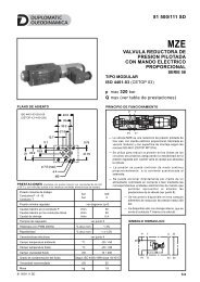
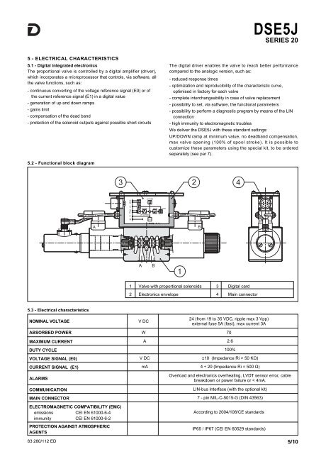
5.2 - Functional block diagram<br />
1 Valve with proportional solenoids 3 Digital card<br />
2 Electronics envelope 4 Main connector<br />
5.3 - Electrical characteristics<br />
NOMINAL VOLTAGE<br />
V DC<br />
24 (from 19 to 35 VDC, ripple max 3 Vpp)<br />
external fuse 5A (fast), max current 3A<br />
ABSORBED POWER W 70<br />
MAXIMUM CURRENT A 2.6<br />
DUTY CYCLE 100%<br />
VOLTAGE SIGNAL (E0) V DC ±10 (Impedance Ri > 50 KΩ)<br />
CURRENT SIGNAL (E1) mA 4 ÷ 20 (Impedance Ri = 500 Ω)<br />
ALARMS<br />
COMMUNICATION<br />
Overload and electronics overheating, LVDT sensor error, cable<br />
breakdown or power failure or < 4mA.<br />
LIN-bus Interface (with the optional kit)<br />
MAIN CONNECTOR 7 - pin MIL-C-5015-G (DIN 43563)<br />
ELECTROMAGNETIC COMPATIBILITY (EMC)<br />
emissions CEI EN 61000-6-4<br />
immunity CEI EN 61000-6-2<br />
PROTECTION AGAINST ATMOSPHERIC<br />
AGENTS<br />
According to 2004/108/CE standards<br />
IP65 / IP67 (CEI EN 60529 standards)<br />
83 280/112 ED 5/10