Handbook for Electric Service (entire)
Handbook for Electric Service (entire)
Handbook for Electric Service (entire)

You also want an ePaper? Increase the reach of your titles
YUMPU automatically turns print PDFs into web optimized ePapers that Google loves.
<strong>Handbook</strong> <strong>for</strong> <strong>Electric</strong> <strong>Service</strong><br />
Foreword<br />
This illustrated <strong>Handbook</strong> <strong>for</strong> <strong>Electric</strong> <strong>Service</strong><br />
clearly defines everyone’s responsibilities<br />
<strong>for</strong> installing new Basic, Large Basic and<br />
Temporary electric service, and the upgrade or<br />
relocation of an existing service. This handbook<br />
was developed to ensure reliable and adequate<br />
service to you, the member, and to improve<br />
communication and coordination between<br />
members, contractors, architects, engineers, civic<br />
planning groups and the Cooperative. These<br />
guidelines cover the most common situations.<br />
There may be cases when additional and/or<br />
different requirements are needed. Following<br />
these guidelines will eliminate extra phone calls<br />
and visits to the job site, saving money <strong>for</strong><br />
electricians, property owners, developers, and<br />
the New Hampshire <strong>Electric</strong> Cooperative.<br />
Details on each type of new service are provided<br />
in this handbook. For details, simply turn to the<br />
Section that describes your situation. If temporary<br />
service is needed while a residence is being<br />
constructed, see Temporary <strong>Service</strong> on page 1.<br />
For in<strong>for</strong>mation on a Basic <strong>Service</strong>, turn to<br />
page 5.<br />
For in<strong>for</strong>mation regarding the installation of<br />
permanent service <strong>for</strong> multifamily and<br />
nonresidential services such as commercial<br />
buildings, condominium complexes, apartment<br />
buildings, and mobile home parks, see Large<br />
Basic <strong>Service</strong> on page 16.<br />
To get answers to general billing or technical questions<br />
and company in<strong>for</strong>mation, call the Cooperative<br />
Member Call Center at 1-800-698-2007.<br />
Be sure to review the <strong>entire</strong> handbook to ensure<br />
you have covered all areas of your service<br />
requirements.<br />
Important In<strong>for</strong>mation<br />
Wiring intended <strong>for</strong> connection to the<br />
Cooperative system must be in accordance with<br />
all applicable local ordinances, State guidelines<br />
and/or Federal requirements such as the<br />
National <strong>Electric</strong>al Code (NEC). It is also strongly<br />
recommended that you use a licensed electrician<br />
whenever dealing with electricity <strong>for</strong> any<br />
reason. No requirement in the handbook is<br />
intended to supersede or conflict with the standards<br />
and regulations of the National <strong>Electric</strong>al<br />
Code or with any state or municipal law, rule or<br />
ordinance now in <strong>for</strong>ce or hereafter enacted.<br />
Also note that services <strong>for</strong> fire pump equipment<br />
are not covered in this manual and must be coordinated<br />
with NHEC engineering staff on a case<br />
by case basis.<br />
i
C o n t e n t s<br />
Temporary <strong>Service</strong> 1<br />
Overhead <strong>Service</strong> 2<br />
Underground <strong>Service</strong> 3<br />
Basic <strong>Service</strong> 5<br />
Requesting <strong>Service</strong> 6<br />
Overhead <strong>Service</strong> 8<br />
Underground <strong>Service</strong> 12<br />
Meter Requirements 14<br />
200 Amp <strong>Service</strong> 15<br />
Large Basic <strong>Service</strong> 16<br />
<strong>Service</strong> Types 16<br />
Overhead <strong>Service</strong> 17<br />
<strong>Service</strong> Equipment Installation<br />
Requirements 18<br />
Underground <strong>Service</strong> 18<br />
<strong>Service</strong>s Greater Than 400 Amps 19<br />
Meter Requirements 20<br />
Single-Phase 120/208 Volt<br />
<strong>Service</strong>s 22<br />
Self-Contained Metering 23<br />
Current Trans<strong>for</strong>mer Metering 23<br />
<strong>Service</strong> Upgrade and Relocation 24<br />
Glossary of Terms 25<br />
Application <strong>for</strong> <strong>Service</strong> 27<br />
Load Data Survey Sheet 28<br />
I m p o r t a n t<br />
P h o n e<br />
N u m b e r s:<br />
General In<strong>for</strong>mation<br />
1-800-698-2007<br />
New <strong>Service</strong>/Upgrade of <strong>Service</strong> In<strong>for</strong>mation<br />
1-800-698-2007<br />
Outage Center<br />
1-800-343-6432<br />
Dig Safe<br />
1-888-344-7233<br />
Web Site<br />
www.nhec.coop<br />
E-Mail<br />
nhechq@nhec.com<br />
For the latest in<strong>for</strong>mation regarding NHEC’s<br />
Schedule of Fees, Charges and Rates, or Terms<br />
and Conditions visit:<br />
www.nhec.com/rates_summaryofrates.php<br />
For the latest listing of NHEC-approved meter<br />
sockets go here and click on the List of Approved<br />
Meter Sockets:<br />
www.nhec.com/education_incentiveprograms.php<br />
For in<strong>for</strong>mation on Net Metered <strong>Service</strong> call<br />
Engineering.<br />
Backup Generator Form 29<br />
Specifications (Specs) 30-57<br />
ii<br />
This <strong>Handbook</strong> <strong>for</strong> <strong>Electric</strong> <strong>Service</strong> is provided by<br />
NHEC as an aid to help members and others better<br />
understand the services available from NHEC. This<br />
<strong>Handbook</strong> <strong>for</strong> <strong>Electric</strong> <strong>Service</strong> may summarize or<br />
explain certain rights and responsibilities of NHEC, its<br />
members and others. This <strong>Handbook</strong> <strong>for</strong> <strong>Electric</strong><br />
<strong>Service</strong> is not a contract and is not intended to limit or<br />
expand any rights or responsibilities of NHEC, its members<br />
or others. Readers are encouraged to refer to the<br />
actual text of NHEC’s Bylaws, NHEC’s Terms and<br />
Conditions, NHEC’s Tariffs, or any relevant contract.
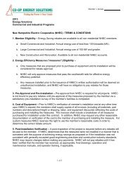
New Hampshire <strong>Electric</strong> Cooperative<br />
<strong>Service</strong> Territory & District Locations<br />
Alton Office<br />
Andover Office<br />
Colebrook Office<br />
Conway Office<br />
Lisbon Office<br />
Alton<br />
Barnstead<br />
Belmont*<br />
Farmington<br />
Gil<strong>for</strong>d<br />
Gilmanton*<br />
Loudon<br />
New Durham<br />
Pittsfield*<br />
Alexandria*<br />
Andover<br />
Belmont*<br />
Bristol<br />
Canterbury<br />
Danbury<br />
Franklin<br />
Gilmanton*<br />
Grafton*<br />
Hill<br />
Northfield<br />
Salisbury<br />
Springfield*<br />
Sutton<br />
Wilmot<br />
Clarksville<br />
Colebrook<br />
Columbia<br />
Dixville<br />
Pittsburg<br />
Stewartstown<br />
Bartlett<br />
Conway<br />
Hales Location<br />
Harts Location<br />
Jackson<br />
Bath<br />
Benton<br />
Easton<br />
Haverhill<br />
Landaff<br />
Lisbon<br />
Littleton<br />
Lyman<br />
Monroe<br />
Sugar Hill<br />
Meredith Office<br />
Ossipee Office<br />
Plymouth Office<br />
Raymond Office<br />
Sunapee Office<br />
Center Harbor*<br />
Holderness*<br />
Laconia<br />
Meredith<br />
Moultonboro*<br />
New Hampton*<br />
Sanbornton*<br />
Sandwich*<br />
Tuftonboro*<br />
Brookfield<br />
Eaton<br />
Effingham<br />
Freedom<br />
Madison<br />
Moultonboro*<br />
Ossipee<br />
Sandwich*<br />
Tamworth<br />
Tuftonboro*<br />
Wakefield<br />
Wolfeboro<br />
Alexandria*<br />
Bridgewater<br />
Campton<br />
Canaan<br />
Center Harbor*<br />
Dorchester<br />
Ellsworth<br />
Grafton*<br />
Groton<br />
Hanover<br />
Hebron<br />
Holderness*<br />
Lincoln<br />
Lyme<br />
New Hampton*<br />
Orange<br />
Or<strong>for</strong>d<br />
Piermont<br />
Plymouth<br />
Rumney<br />
Sandwich*<br />
Thornton<br />
Warren<br />
Waterville<br />
Wentworth<br />
Woodstock<br />
Allenstown<br />
Auburn<br />
Brentwood<br />
Candia<br />
Chester<br />
Danville<br />
Deerfield<br />
Derry<br />
Durham<br />
Epping<br />
Epsom<br />
Fremont<br />
Kingston<br />
Lee<br />
Londonderry<br />
Northwood<br />
Nottingham<br />
Pittsfield*<br />
Raymond<br />
Sandown<br />
Acworth<br />
Charlestown<br />
Claremont<br />
Cornish<br />
Croydon<br />
Enfield<br />
Goshen<br />
Grafton*<br />
Langdon<br />
Lempster<br />
Marlow<br />
Newport<br />
Plainfield<br />
Springfield*<br />
Sunapee<br />
Unity<br />
Washington<br />
*District serving area depends on pole location. If you have further questions concerning your service<br />
territory, please call the Cooperative at 1-800-698-2007.<br />
iii
N e w S e r v i c e<br />
C h e c k S h e e t<br />
What the member should establish be<strong>for</strong>e<br />
contacting the NHEC:<br />
❏<br />
A foundation in place.<br />
In<strong>for</strong>mation NHEC will require:<br />
❏ Application (page 27).<br />
❏ Load data or service entrance size<br />
(page 28).<br />
❏ Commitment to either an overhead or<br />
underground service.<br />
❏ Date service is needed.<br />
❏ A location <strong>for</strong> the temporary service<br />
(subject to NHEC approval).<br />
❏ A location <strong>for</strong> the permanent service<br />
(subject to NHEC approval).<br />
❏ Easement info (book and page # of<br />
deed, tax lot #, bordering lot ownership<br />
with applicable tax lot #’s).<br />
Check these items be<strong>for</strong>e calling <strong>for</strong> a<br />
construction date:<br />
❏<br />
❏<br />
❏<br />
❏<br />
❏<br />
Have you provided the Cooperative<br />
with all the necessary documentation<br />
such as an easement and application<br />
If you signed an easement, did you<br />
use black ink and have it notarized<br />
Have you made all necessary prepayments<br />
Have you (or your electrician) set the<br />
service up as the applicable NHEC<br />
specification in this handbook shows<br />
Is the service located as you and our<br />
Field Representative discussed<br />
Please understand that you will be billed if,<br />
upon your request <strong>for</strong> a service connection,<br />
an NHEC line-crew makes a visit to the job<br />
site and is unable to make a connection or<br />
finds the entrance does not meet NHEC specs.<br />
P o l i c i e s<br />
New Hampshire <strong>Electric</strong> Cooperative, Inc.<br />
strives to render dependable electric<br />
delivery service in accordance with the<br />
Tariff <strong>for</strong> Delivery <strong>Service</strong>, Transition/Default<br />
Power <strong>Service</strong> and <strong>Service</strong>s to Competitive<br />
Suppliers. Application <strong>for</strong> delivery of electric<br />
service may be made by visiting or calling our<br />
main business office at 1-800-698-2007.<br />
Whether or not a signed application <strong>for</strong> service<br />
is made by the member and accepted by NHEC,<br />
the rendering of the service by NHEC and its use<br />
by the member shall be deemed a contract<br />
between the parties and subject to provisions of<br />
the Tariff.<br />
NHEC reserves the right to reject any application<br />
<strong>for</strong> service made by, or <strong>for</strong> the benefit of a<br />
<strong>for</strong>mer member who is indebted to NHEC <strong>for</strong><br />
delivery of electric service previously furnished to<br />
them. NHEC reserves the right to reject any<br />
application <strong>for</strong> service if the amount or nature of<br />
the service, or the distance of the premises to be<br />
served from an existing suitable line, or the difficulty<br />
of access thereto is such that the estimated<br />
income from the service applied <strong>for</strong> is insufficient<br />
to yield a reasonable return to NHEC, unless such<br />
application is accompanied by cash payment.<br />
The applicant <strong>for</strong> service will provide, without<br />
expense or cost to NHEC, the necessary permits,<br />
consents, or easements <strong>for</strong> a satisfactory right of<br />
way <strong>for</strong> the erection, maintenance and operation<br />
of a line, including the right to cut and trim trees<br />
and bushes wherever necessary along private<br />
property.<br />
The installation of a new service is a joint ef<strong>for</strong>t<br />
between the owner, the contractor, and NHEC.<br />
This handbook is provided to you, the member, to<br />
help you become aware of our policies and<br />
practices. This should ensure a timely and costeffective<br />
installation.<br />
iv
Temporary <strong>Service</strong><br />
Introduction<br />
This Section provides in<strong>for</strong>mation <strong>for</strong> installing<br />
a new temporary service.<br />
Temporary service is defined as a means of<br />
supplying electricity to a site <strong>for</strong> less than 12<br />
months. Usually a temporary service is installed<br />
to provide power during the construction phase<br />
of a project, while provisions are being made <strong>for</strong><br />
permanent power.<br />
Getting started<br />
Installing temporary new electrical service to a<br />
home/building is a joint project between you<br />
(the member) and the Cooperative.<br />
The Cooperative is responsible <strong>for</strong> installing the<br />
service lines to bring power to the temporary<br />
residence/building and <strong>for</strong> installing a meter in<br />
the meter socket.<br />
The member needs to complete several items<br />
be<strong>for</strong>e the Cooperative can energize temporary<br />
service such as:<br />
• Call the Cooperative at 1-800-698-2007<br />
to begin the service order process.<br />
• Install the required service equipment and<br />
structure.<br />
• An on-site meeting with a Line Design<br />
Technician or other Cooperative<br />
representative.<br />
• Obtain an electrical inspection and<br />
approval of the service equipment and<br />
structure. The call <strong>for</strong> this inspection is<br />
made by the member or the electrical<br />
contractor.<br />
• After the electrical inspection is<br />
complete, call the Cooperative’s<br />
Engineering Department to request<br />
that service be energized.<br />
The remainder of this Section will assist with this<br />
process.<br />
Overhead or underground<br />
service<br />
The two types of temporary services are overhead<br />
and underground. If the existing power<br />
system in the area is a series of poles as shown<br />
in Figure 1 on page 6, the area is served<br />
overhead, and the temporary service will typically<br />
be overhead. If the area is served underground,<br />
items such as those shown in Figures 2, 3 and 4<br />
on page 6 should be visible. In this case, the<br />
temporary service will be underground.<br />
If none of these items (Figures 1 through 3)<br />
shown on page 6 exist in the area, or <strong>for</strong> service<br />
other than 120/240 volts, 100-400 amps, single<br />
phase, or <strong>for</strong> answers to questions, call the<br />
Cooperative at 1-800-698-2007.<br />
Inspections and codes<br />
This handbook should be used only as a guide. It<br />
does not cover all federal, state, and local code<br />
requirements. It is the member’s responsibility to<br />
ensure the project complies with the most recent<br />
issue of the National <strong>Electric</strong>al Code and any<br />
other federal, state, or local codes that apply.<br />
Once the member’s service equipment is<br />
installed, the state, or the city with jurisdiction,<br />
may require that the installation pass an electrical<br />
inspection be<strong>for</strong>e the Cooperative can complete<br />
the connection to the electrical system. The<br />
member is responsible <strong>for</strong> requesting and passing<br />
this inspection.<br />
Underground locates<br />
Three days prior to any trenching or excavation<br />
work, the member is required to call <strong>for</strong> underground<br />
utility locates. Underground utility locates<br />
are available by calling the Dig Safe Underground<br />
Location Center at 1-888-344-7233. The Center<br />
has established a system called the “One-Call”<br />
system. One call to Dig Safe will notify the<br />
utilities, or a locating service, that locates are<br />
required. However, in some areas, not all utilities<br />
are members of the One-Call system. In those<br />
areas, the member must contact the utilities<br />
individually.<br />
There is no charge <strong>for</strong> this service.<br />
To get a locate, call the Utilities Underground<br />
Location Center One-Call number, at<br />
1-888-344-7233.<br />
1
A color code system has been established to<br />
identify each utility so everyone can see what has<br />
been located. The color codes are:<br />
Color<br />
Red<br />
Yellow<br />
Orange<br />
Blue<br />
Green<br />
White<br />
Utility<br />
<strong>Electric</strong><br />
Gas/Oil<br />
Telephone/Cable TV<br />
Water<br />
Sewer<br />
Area to be located<br />
Any digging within 24 inches of either side of the<br />
location markings must be done by hand.<br />
Meter socket requirements<br />
For the latest listing of NHEC-approved meter<br />
sockets, go here and click on the List of Approved<br />
Meter Sockets:<br />
www.nhec.com/education_incentiveprograms.php<br />
Temporary Overhead <strong>Service</strong><br />
The process and costs of obtaining temporary overhead<br />
service varies, depending upon the location of<br />
the Cooperative’s existing facilities. After meeting<br />
with the Co-op Representative in the field, the<br />
member installs the temporary service equipment<br />
and structure, has it inspected, and calls the<br />
Cooperative at 1-800-698-2007 to discuss fees and<br />
to order service. Once the above items are completed,<br />
service will usually be connected as soon as all<br />
required documentation, prepayments, and permits<br />
have been completed, and scheduling allows.<br />
For help with technical questions about<br />
service in the area, call the Cooperative’s<br />
Engineering Department.<br />
Meter location<br />
A temporary meter service structure should be<br />
located on the property within 50 feet of the<br />
power pole that will serve the site. This limitation<br />
ensures that the temporary service pole can<br />
withstand the weight of the conductor. If a<br />
distance greater than 50 feet is required, contact<br />
the Cooperative’s Engineering Department <strong>for</strong><br />
approval prior to construction. A taller post with<br />
additional bracing might be required. In all<br />
cases the post should be set in the ground a<br />
minimum of 3 feet deep.<br />
In addition to the distance limitation<br />
mentioned above, consider the following:<br />
• The path that the service line will take<br />
should not cross property belonging to<br />
others.<br />
• If the service line will pass through<br />
trees or brush, a path <strong>for</strong> the line must be<br />
cleared to allow Cooperative service personnel<br />
to run the line and to allow lines to<br />
hang without contacting trees or limbs.<br />
Maintaining this clear path is the member’s<br />
responsibility.<br />
• The service line path should avoid areas<br />
where vehicular traffic will occur, unless<br />
the temporary service post height is<br />
increased to provide adequate clearance.<br />
See Spec. TS-1 on page 33 <strong>for</strong> clearance<br />
requirements.<br />
The Cooperative will answer questions and advise<br />
on special situations.<br />
Clearance requirements<br />
The National <strong>Electric</strong>al Code (NEC) and the<br />
National <strong>Electric</strong>al Safety Code (NESC) have<br />
established minimum clearance requirements to<br />
maintain safe height requirements <strong>for</strong> electrical<br />
conductors over various terrains.<br />
The NEC and NESC require the lowest point of a<br />
service conductor to be at least 12 feet above the<br />
ground. The bottom of the drip loop must be a<br />
minimum of 10 feet above the ground. Figure 6<br />
on page 10 shows the clearance requirements <strong>for</strong><br />
the types of terrain most commonly encountered.<br />
It is not the member’s responsibility to string the<br />
conductor, but the point of attachment at the<br />
service structure must allow the Cooperative to<br />
install the conductor and maintain required<br />
clearances.<br />
For further details, consult the current issue of the<br />
NEC, or contact the state or local electrical<br />
inspector <strong>for</strong> the area.<br />
2
<strong>Service</strong> installation<br />
The following items must be completed by the<br />
member be<strong>for</strong>e the Cooperative can energize<br />
service:<br />
• Contact a Cooperative representative<br />
to request a temporary service.<br />
• Obtain an electrical work permit from<br />
the inspecting agency.<br />
• Install temporary service structure and<br />
equipment to Cooperative Specifications.<br />
• Obtain an electrical inspection.<br />
After these items are completed, call the<br />
Cooperative’s Engineering Department to<br />
announce that the installation has been inspected<br />
and is ready <strong>for</strong> temporary service.<br />
Spec. TS-1 on page 33, illustrates the<br />
recommended temporary overhead service<br />
installation. The specifications shown are the<br />
minimum acceptable.<br />
Do not deviate from the installation standards<br />
without approval from the Cooperative.<br />
Temporary Underground<br />
<strong>Service</strong><br />
Temporary underground service is available<br />
where the existing power facilities are installed<br />
underground. If there is power in the area, but<br />
the power lines are not visible, the power system<br />
is likely to be installed underground.<br />
The process and cost of obtaining temporary<br />
underground service varies, depending on the<br />
location of existing power facilities. After a field<br />
meeting with the Co-op Field Representative,<br />
install the meter socket, service pedestal and<br />
service wire (see Specs. UTS-1, page 41 and<br />
UTS-2, page 42), obtain an inspection, and call<br />
the Cooperative to connect service.<br />
For help with questions about Cooperative<br />
facilities at the job site, contact the Cooperative’s<br />
Engineering Department.<br />
The cost <strong>for</strong> temporary service depends on the<br />
extent of special engineering required.<br />
Meter location<br />
Locate the meter pedestal on the property<br />
no more than 5 feet from the trans<strong>for</strong>mer, stubup,<br />
or handhole.<br />
If a distance greater than 5 feet is necessary,<br />
contact the Cooperative Representative <strong>for</strong><br />
approval prior to construction.<br />
Temporary service installation<br />
The following items must be completed prior to<br />
energizing the service:<br />
• Contact the Cooperative and request<br />
a temporary service.<br />
• Obtain an electrical work permit from<br />
the inspecting agency.<br />
• Locate underground service (call Dig Safe).<br />
• Install the meter pedestal and meter<br />
socket in the appropriate location.<br />
• Provide the appropriately sized<br />
conductor from the meter socket to the<br />
Cooperative’s connection point. Leave<br />
5 feet of extra wire at a stubup or<br />
handhole, and 10 feet out of conduit<br />
at the trans<strong>for</strong>mer vault. Consult the<br />
NEC <strong>for</strong> the appropriate wire sizes.<br />
• Obtain an electrical inspection where<br />
required by the local authority.<br />
• Cover wire leading to the connection<br />
point, except where Cooperative<br />
personnel will be splicing their wire to the<br />
member’s.<br />
• Call the Cooperative to announce that<br />
the installation has been inspected and is<br />
ready <strong>for</strong> temporary service.<br />
Trenching requirements<br />
It is the member’s responsibility to provide<br />
a buried cable from the meter base to the<br />
Cooperative’s trans<strong>for</strong>mer or handhole.<br />
The cable and conduit installed by the member<br />
should be sized per the NEC and have a<br />
minimum cover of 36 inches.<br />
If the connection point is a handhole or trans<strong>for</strong>mer,<br />
the member trenches to the nearest side<br />
and leaves the wires exposed. If any other conductors<br />
are discovered while digging, leave them<br />
covered. If further trenching is required,<br />
Cooperative personnel will complete it.<br />
3
Remember to call Dig Safe at 1-888-344-7233<br />
and request buried cable locations 72 hours<br />
be<strong>for</strong>e digging. Any trenching within 24 inches<br />
of existing underground facilities must be done<br />
by hand.<br />
Specs. UTS-1 and UTS-2, on pages 41 and 42,<br />
illustrate the recommended temporary<br />
underground service. Note the dimensions<br />
shown. Deviations from this recommended<br />
standard can result in a delay in receiving<br />
service, or in service being denied. Contact the<br />
Cooperative <strong>for</strong> answers to any questions.<br />
New <strong>Service</strong> Checklist<br />
To improve our efficiency, we ask that you<br />
review the in<strong>for</strong>mation in this handbook<br />
thoroughly, including the service specifications.<br />
Reviewing this important in<strong>for</strong>mation<br />
be<strong>for</strong>e calling us <strong>for</strong> connection will avoid<br />
unnecessary delays and/or billing. An unsuccessful<br />
visit to connect the service uses valuable<br />
time and resources. Please understand<br />
that you will be billed if, upon your request,<br />
the Cooperative makes a visit to the job site<br />
and is unable to make the connection.<br />
Please review the following checklist<br />
and ensure you have completed all<br />
applicable steps be<strong>for</strong>e calling us <strong>for</strong><br />
your service connection:<br />
❏ Have you provided the Cooperative with all necessary<br />
documentation such as an easement and application<br />
✓<br />
❏ Have you made all necessary up-front payments<br />
❏ If you signed an easement, did you use black ink and<br />
have it notarized<br />
❏ Have you (or your electrician) set the service up as the<br />
applicable NHEC specification in this handbook shows<br />
❏ Is the service located as you and our Field Representative<br />
discussed<br />
If you have any questions concerning any of these items,<br />
please call the Cooperative at 1-800-698-2007 or the<br />
Field Representative <strong>for</strong> your area.<br />
4
Basic <strong>Service</strong><br />
Introduction<br />
This Section provides in<strong>for</strong>mation regarding a<br />
new electric Basic <strong>Service</strong> <strong>for</strong> a single phase<br />
service less than or equal to 400 amps, and a<br />
three phase service less than 50kW. It also<br />
includes helpful in<strong>for</strong>mation from the National<br />
<strong>Electric</strong>al Code (NEC). The Cooperative<br />
Specifications <strong>for</strong> <strong>Electric</strong> <strong>Service</strong> are included at<br />
the back of the handbook.<br />
This Section answers common questions, such as:<br />
• Where should the meter socket be<br />
installed<br />
• How tall does the service mast have to<br />
be<br />
• What are the size requirements <strong>for</strong> the<br />
meter socket<br />
• What does the member have to do to<br />
get underground service<br />
• How does the member install a meter<br />
socket<br />
• How are existing underground utilities<br />
located be<strong>for</strong>e digging starts<br />
Getting started<br />
Installing new electrical service to a home is a<br />
joint project between you (the member) and the<br />
Cooperative.<br />
The Cooperative is responsible <strong>for</strong> installing the<br />
service lines to bring power to the building, and<br />
<strong>for</strong> installing a meter in the meter socket.<br />
The member is responsible <strong>for</strong>:<br />
• Setting up the temporary service if one<br />
is required (See Temporary <strong>Service</strong> Section).<br />
• Choosing between overhead or underground<br />
service.<br />
• Obtaining the meter socket and<br />
service entrance.<br />
• All electrical wiring in the building<br />
including service entrance facilities.<br />
• Obtaining any required easements,<br />
permits and inspections.<br />
• Payment to the Cooperative <strong>for</strong> all fees.<br />
• Specifying the size and type of service.<br />
• Submitting a Load Data sheet.<br />
• Locating the meter socket in a mutually<br />
agreed upon location with the Cooperative.<br />
Setting up a new service<br />
To set up a new service, call the Cooperative at<br />
1-800-698-2007. A representative will request<br />
general billing in<strong>for</strong>mation, discuss fees, and the<br />
address <strong>for</strong> the new service. (New addresses are<br />
obtained from the United States Postal <strong>Service</strong>).<br />
An on-site meeting with a Cooperative Field<br />
Representative can be scheduled once this<br />
in<strong>for</strong>mation is obtained and the necessary fees<br />
are paid.<br />
Please bear in mind that because the<br />
Cooperative has a limited work<strong>for</strong>ce, and a<br />
demanding workload, meeting with a Field<br />
Representative to design your service can take<br />
two weeks or longer and then scheduling the<br />
construction could add additional time. Please<br />
contact NHEC <strong>for</strong> electrical service as soon as<br />
your building plans are finalized and have been<br />
approved by the local authorities.<br />
Please contact the phone company covering your<br />
area <strong>for</strong> service at the same time you request<br />
electrical service.<br />
Overhead or underground<br />
service<br />
Two types of electrical service are available —<br />
overhead and underground. Underground service<br />
is available to everyone. Overhead service<br />
is available if the Cooperative’s system is overhead,<br />
and if local ordinances allow it. It is the<br />
member’s responsibility to be aware of any<br />
applicable local codes and ordinances.<br />
To determine if the electrical system already<br />
installed in the area is overhead or underground,<br />
check the facilities along the road. If the power<br />
system is overhead, a series of poles similar to<br />
Figure 1, page 6 will be visible. If the power system<br />
is underground, there will be items like those<br />
in Figures 2 through 4, page 6.<br />
5
If the system is underground, the only option is<br />
an underground service. Refer to the<br />
Underground <strong>Service</strong> portion of this Section <strong>for</strong><br />
those specific requirements.<br />
Figure 1 Pole with Trans<strong>for</strong>mer<br />
For help determining which type of system is<br />
installed in your area, call the Cooperative’s<br />
Engineering Department.<br />
Requesting <strong>Service</strong><br />
Be<strong>for</strong>e new service is installed, the member<br />
needs to contact the Cooperative to request that<br />
a service order be created. <strong>Service</strong> orders will<br />
link the Cooperative’s field personnel with the<br />
in<strong>for</strong>mation they need to install permanent<br />
service.<br />
The Cooperative service representative may ask<br />
the following questions:<br />
6<br />
Figure 2 Padmount trans<strong>for</strong>mer<br />
Figure 3 Secondary handhole<br />
Figure 4 Secondary pedestal<br />
If the system is overhead, and the new service<br />
will be overhead, the requirements <strong>for</strong> overhead<br />
services can be found in the Overhead <strong>Service</strong><br />
Specification section.<br />
If the system is overhead, but the new service will<br />
be underground, those requirements are in the<br />
Underground <strong>Service</strong> section.<br />
• Will a temporary service be needed<br />
• What is the service <strong>for</strong> (home, barn,<br />
shop, etc.)<br />
• Whose name will the service be under<br />
• What is the address of the new service<br />
• Is the property cleared<br />
• Is the foundation in and approved,<br />
and is there an approved<br />
septic plan <strong>for</strong> this site<br />
• What is the daytime phone number of<br />
the property owner<br />
• What is the name and daytime phone<br />
number of the electrician<br />
• What is the name and daytime phone<br />
number of the building contractor<br />
• Have you had service with the<br />
Cooperative be<strong>for</strong>e<br />
• The residence has how many square<br />
feet<br />
• Will the house heat be electric<br />
• Will the water heater be gas or electric<br />
• What size service panel will be<br />
installed<br />
• When will the site be ready <strong>for</strong> service<br />
• Will the electric service be overhead<br />
or underground<br />
• If overhead, is it allowed by local<br />
ordinances and covenants<br />
• Is the existing power system in the<br />
area overhead or underground<br />
• What is the pole number of pole<br />
nearest the house site<br />
• Is this service to be located on a<br />
scenic road or within a historic district
• What is the nearest neighbor’s name<br />
or meter number<br />
• If the existing system is overhead and<br />
the new service is to be overhead:<br />
- Is the new meter location less than<br />
100 feet from the nearest power pole<br />
- Does the pole have a trans<strong>for</strong>mer on<br />
it (See Figure 1.)<br />
- Will the service line cross property<br />
owned by anyone else<br />
• If the existing power system is<br />
overhead and the new service is to be<br />
underground:<br />
- Is the new meter location less than<br />
300 feet from the nearest power<br />
pole<br />
- Does the pole have a trans<strong>for</strong>mer on<br />
it (See Figure 1.)<br />
• Is the existing system underground<br />
(Only underground service is<br />
available in this case.)<br />
• Is the new meter location less than<br />
300 feet from the nearest Cooperative<br />
trans<strong>for</strong>mer (See Figure 2.)<br />
Inspections and codes<br />
This handbook should be used only as a guide. It<br />
does not cover all federal, state, and local code<br />
requirements. It is the member’s responsibility to<br />
ensure the project complies with the most recent<br />
issue of the National <strong>Electric</strong>al Code and any<br />
other federal, state, or local codes that apply.<br />
Once the member’s service equipment is<br />
installed, the state, or the town with jurisdiction,<br />
may require that the installation pass an electrical<br />
inspection be<strong>for</strong>e the Cooperative can complete<br />
the connection to the electrical system. The member<br />
is responsible <strong>for</strong> requesting and passing this<br />
inspection.<br />
Easements, licenses and permits<br />
It is the responsibility of the applicant to provide<br />
the Cooperative with the necessary permits, consents<br />
or easements needed to construct a line,<br />
without expense to the Cooperative. Any private<br />
property that the Cooperative crosses to provide<br />
service to an applicant will require an easement.<br />
The applicant must pay all recording fees.<br />
Contacting other utilities<br />
New construction typically involves the installation<br />
of telephone cables, cable television cables<br />
and natural gas lines, as well as power cables.<br />
It is the member’s responsibility to notify each<br />
utility that will provide service to the home.<br />
Check the local phone book <strong>for</strong> their numbers.<br />
For each utility, note the contact name and phone<br />
number, and let each utility know which other<br />
utilities will be providing new service.<br />
<strong>Service</strong> ratings available<br />
Several sizes of services are available <strong>for</strong> the<br />
Basic <strong>Service</strong>.<br />
The size of service depends upon the size of the<br />
home or business and the power requirements of<br />
the appliances and equipment installed. The<br />
Cooperative does not determine the size of the<br />
member’s service.<br />
Voltage Ampere Rating Typical Use<br />
120/240* 100 Amps** Small Sized Homes<br />
120/240 200 Amps Medium Homes<br />
(most common size service)<br />
120/240 400 Amps Large Homes<br />
120/208
The reasons <strong>for</strong> these requirements are:<br />
• So meter readers can read the meter in a<br />
safe, cost effective manner.<br />
• So the Cooperative can efficiently<br />
maintain the meter.<br />
• So Cooperative employees can stay out<br />
of the member’s backyard.<br />
• If there is a fire or other disaster, the<br />
Cooperative can disconnect service.<br />
Removing and installing meters<br />
Only personnel who are qualified and authorized<br />
by the Cooperative are permitted to remove and<br />
install meters. In special circumstances,<br />
exceptions may be granted to qualified electrical<br />
contractors by contacting the Cooperative’s meter<br />
department, service center supervisor, or a<br />
designated representative. Note: With some<br />
types of meter sockets, removal of the<br />
meter does not de-energize the<br />
member’s service.<br />
Underground locates<br />
Seventy-two (72) hours prior to any trenching or<br />
excavation work, the member is required to call<br />
<strong>for</strong> underground utility locates. Underground<br />
utility locates are available by calling the<br />
“Dig Safe” Location Center. The Center has<br />
established a system called the “One-Call”<br />
system. One call to the Dig Safe Location Center<br />
will notify the utilities, or a locating service, that<br />
locates are required. However in some areas,<br />
not all utilities belong to the One-Call system. In<br />
those areas the member must contact the utilities<br />
individually. This service is free.<br />
To locate underground services, call the Utilities<br />
Underground Location Center One-Call number<br />
at 1-888-344-7233. Be sure to have the<br />
nearest pole number to give to Dig Safe when<br />
you call.<br />
The state has established a color code system to<br />
identify each utility so everyone can see what<br />
has been located. The color codes are:<br />
Color<br />
Red<br />
Yellow<br />
Orange<br />
Blue<br />
Green<br />
White<br />
Utility<br />
<strong>Electric</strong><br />
Gas/Oil<br />
Telephone/Cable TV TV<br />
Water<br />
Sewer<br />
Area to be located<br />
Any digging within 24 inches of either side of<br />
the location markings must be done by hand.<br />
Grounding<br />
All meter sockets, enclosures and conduit must<br />
be bonded and grounded in accordance with<br />
Articles 230 and 250 of the latest edition of the<br />
NEC. When self-contained meter sockets are<br />
used, the neutral conductor must be connected to<br />
the neutral terminal in the socket.<br />
Basic Overhead <strong>Service</strong> <strong>Service</strong><br />
General requirements<br />
The following checklist will assist in preparing <strong>for</strong><br />
the installation of overhead service. After the<br />
member has completed these items, the<br />
Cooperative will install the service line and<br />
meter.<br />
• Check if any local ordinances or<br />
covenants prevent the installation of an<br />
overhead service.<br />
• Determine an acceptable location <strong>for</strong> the<br />
meter socket.<br />
• Ask the Cooperative where the service<br />
line will originate from. Call the<br />
Engineering office, and arrange a field<br />
meeting to review the service installation<br />
and choose a mutually agreeable meter<br />
location.<br />
• Provide a clear path from the<br />
Cooperative’s pole to the member’s<br />
service location.<br />
• Install the service equipment.<br />
8
• Install the service entrance conductors,<br />
with 36 inches left exposed at the<br />
weatherhead. See Figure 5 below.<br />
• Verify that the service height requirements<br />
have been met. See Cooperative <strong>Service</strong><br />
Specifications (Specs) on pages 30-57.<br />
• Have the town or state inspect the service<br />
equipment.<br />
• Make sure service locaton is at finished<br />
grade and readily accessible.<br />
• Call the Cooperative’s Engineering Dept.<br />
<strong>for</strong> arrangements to have service<br />
hooked up.<br />
Getting started<br />
The first step when installing<br />
new overhead service is<br />
to contact the Cooperative<br />
at 1-800-698-2007 to begin<br />
the service order process.<br />
Next, determine the location of the meter socket.<br />
The meter socket should be located outside, on<br />
the front one-third of the structure closest to<br />
normal public access and Cooperative service<br />
point.<br />
Another factor to consider when choosing the<br />
location <strong>for</strong> the meter socket is what types of<br />
terrain the line will be crossing.<br />
<strong>Service</strong> requirements<br />
A service is defined by the National <strong>Electric</strong>al<br />
Code as “conductors and equipment <strong>for</strong> delivering<br />
energy from the electricity supply system to<br />
the wiring system of the premises served”. The<br />
member is responsible <strong>for</strong> the installation of the<br />
service entrance up to and including the weatherhead.<br />
All of the service entrance specifications<br />
are shown in the <strong>Service</strong> Specifications section of<br />
this book. The most common <strong>for</strong>m of service<br />
entrance installation in the NHEC service area is<br />
shown in specification SE-1, page 34. Also, see<br />
Figure 5 <strong>for</strong> typical installation.<br />
Height requirements<br />
The top of a service entrance must be at least 15<br />
feet above final grade to maintain minimum<br />
clearances over the property. Additional height<br />
may be required depending upon the location<br />
and type of structure or terrain which the service<br />
line passes over. Figure 6, page 10, illustrates<br />
some of the minimum clearances that must be<br />
maintained.<br />
<strong>Service</strong> lines passing over the roof of another<br />
structure, but not attached to that structure, must<br />
maintain the minimum clearances shown in<br />
Figure 7, page 10. <strong>Service</strong> lines passing over a<br />
deck must maintain a minimum clearance of 11<br />
feet. See Figure 7, page 10.<br />
Figure 5 Typical overhead service installation<br />
9
Figure 6 Minimum vertical clearances from ground<br />
Members with questions about the proper height<br />
of a service entrance are advised to contact the<br />
Cooperative’s Engineering office <strong>for</strong> guidance.<br />
Clearances from building<br />
openings and gas meters<br />
A minimum clearance of 3 feet is required<br />
between service lines and windows, doors,<br />
porches, fire escapes, or similar openings.<br />
A minimum horizontal clearance of 3 feet is<br />
required between electric service equipment and<br />
natural gas metering equipment. See Figure 12<br />
on page 18.<br />
<strong>Service</strong> mast requirements<br />
A service mast consists of a steel conduit that<br />
runs vertically from the top of the meter socket<br />
through the roof. It contains service entrance<br />
conductors and typically supports one end of the<br />
service line. <strong>Service</strong> masts are necessary when<br />
installing some overhead service, and are<br />
installed by the member or the electrical contractor.<br />
The requirements <strong>for</strong> the installation of a service<br />
mast are covered in the NEC, and Cooperative<br />
Spec. SE-4, page 37. Some common specs or<br />
requirements are described next.<br />
The NEC also requires that the service mast<br />
maintain minimum clearances above the roof.<br />
The clearance required depends upon the slope<br />
of the roof, and whether or not the service line is<br />
attached to the structure. Specification SE-4 in<br />
the rear of this booklet is one example of a<br />
service mast installation with the service line<br />
attached to the mast. For other options and<br />
details consult the NEC.<br />
Additional mast supports, typically a guy or a<br />
brace, are required <strong>for</strong> any service line over 50<br />
feet in length. Guys and braces are installed to<br />
prevent the weight of the service line from pulling<br />
the service mast away from the house. Further<br />
in<strong>for</strong>mation regarding guying and bracing<br />
service masts is available in the NEC, or by<br />
contacting the Cooperative.<br />
Min.<br />
10<br />
Figure 7 Minimum clearances over other structures
Additional mast supports are required when:<br />
• The service line is over 50 feet long.<br />
• The top of the service mast is more than<br />
26 inches above the roof.<br />
See Figure 8 <strong>for</strong> an example of a service mast<br />
guy.<br />
<strong>for</strong> the area, or contact an electrical contractor.<br />
Manufactured homes<br />
When installing overhead service to a manufactured<br />
home (not a mobile home), service<br />
equipment can be installed one of two ways:<br />
1. On a Cooperative-owned meter pole, see<br />
specification SE-2 on page 35, or<br />
2. On the manufactured home, if both of the<br />
following conditions are met:<br />
a. The manufacturer installed the<br />
service equipment at the time the<br />
home was built.<br />
b. The service equipment meets<br />
the meter socket requirements<br />
(see Figure 9 below) <strong>for</strong> 100<br />
and 200 amp sockets.<br />
Figure 8 <strong>Service</strong> mast guying<br />
<strong>Service</strong> equipment installation<br />
requirements<br />
After determining the meter socket location, the<br />
service route, the height of the service mast, and<br />
the size of the service equipment (100 amps,<br />
200 amps, or 400 amps, etc.), installation of the<br />
service equipment can begin.<br />
The equipment will be installed per Figure 9.<br />
Deviations require prior approval by the<br />
Cooperative.<br />
Once the member has installed the meter socket<br />
and mast, the next task is to install the service<br />
entrance conductor. The service entrance conductor<br />
is the wiring that connects to the top lugs<br />
in the meter socket and runs upward through the<br />
service mast. The service entrance conductors<br />
must be sized according to the NEC and to the<br />
rating of the meter socket. When installing the<br />
wire, leave at least 36 inches of it exposed at the<br />
end of the weatherhead to allow the Cooperative<br />
to connect the service line to it. When installing<br />
the meter socket, make sure the center of the<br />
meter will be between 5 and 5 1/2 feet, above<br />
finished grade.<br />
For help with the installation of service equipment,<br />
consult the NEC, call the inspecting agency<br />
Figure 9 Surface-mounted meter socket<br />
11
Meter sockets installed on manufactured homes<br />
must:<br />
• Be located on an outside wall of the<br />
home.<br />
• Be located on the front one-third of the<br />
home closest to normal public access,<br />
and Cooperative service point.<br />
• Be between 5 and 5 1/2 feet above<br />
finished grade to the center of the meter.<br />
• Be outside of a walkway.<br />
• Be outside an area subject to being fenced.<br />
And<br />
• Meter location must be mutually agreed<br />
upon with the Cooperative prior to<br />
installation.<br />
• The top of the service mast must be in<br />
compliance with the latest versions of the<br />
National <strong>Electric</strong>al Code. For typical height<br />
requirements see Figure 7 on page 10.<br />
Basic Underground <strong>Service</strong><br />
General requirements<br />
The following is a checklist <strong>for</strong> use as a guide<br />
when preparing <strong>for</strong> the installation of underground<br />
service. Once the member has completed<br />
these items, the Cooperative will install the<br />
service line and meter.<br />
• Locate the origination point of the service<br />
line by meeting with a Cooperative Field<br />
Representative. Also determine an acceptable<br />
location <strong>for</strong> the meter socket.<br />
• Dig a trench from the meter socket to the<br />
location where the service line will originate.<br />
See Page 38 in the back of this booklet.<br />
• Provide conduit and pull ropes according<br />
to Cooperative specifications. See<br />
Installation Requirements <strong>for</strong> Underground<br />
Conduit Systems on Page 38.<br />
• Install all member-owned service equipment.<br />
• Have the Cooperative inspect the<br />
installation while the trench is still open<br />
and have the town or state inspect as<br />
required. The Cooperative requires a<br />
24-hour notification.<br />
• Call the Cooperative to have service<br />
connected when complete.<br />
Getting started<br />
The first step when installing new underground<br />
service is to contact the Cooperative at<br />
1-800-698-2007 to arrange <strong>for</strong> a field visit to<br />
discuss the service requirements.<br />
Next, determine the location of the meter socket.<br />
As stated previously, the meter socket should be<br />
located outside and on the front one-third of the<br />
building closest to normal public and<br />
Cooperative access. The location of the meter<br />
must be a mutually agreed upon location<br />
between the member and the Cooperative.<br />
When choosing a meter socket location be sure<br />
to consider the types of terrain where the service<br />
line will be buried. The Cooperative is responsible<br />
<strong>for</strong> repairing the service line if it ever fails. The<br />
installation is subject to being dug up at some<br />
time in the future. Because of this, it is in the<br />
member’s best interest to be sure the service line<br />
route can be easily reached and excavated.<br />
The member must provide and install conduit. The<br />
conduit must be at least three-inch gray, electrical<br />
grade. Conduit in the trench should be at least<br />
Schedule 40, buried 36 inches deep. Any<br />
service conduit crossing under a road shall be<br />
Schedule 80. Any conduit <strong>for</strong> riser material will<br />
be Schedule 80 or galvanized steel. White<br />
water pipe or sewer pipe is not acceptable. Gray<br />
conduit signifies that electrical, or communications<br />
wires are inside. Consult the specifications<br />
in the back of this handbook.<br />
All member-installed continuous conduit runs must<br />
not contain more than 180 degrees of installed<br />
factory sweeps. Conduit runs of more than 10 feet<br />
must have a pull rope installed in the conduit.<br />
Rope must be polypropylene, 1/4 inch in diameter.<br />
Trenching requirements<br />
The member must provide a trench from the meter<br />
socket to the pole or device where the service<br />
line will originate. The trench must be free of all<br />
rocks and construction debris. See the Installation<br />
Requirements <strong>for</strong> Underground Conduit Systems<br />
on Page 38. The trench must be a minimum of 5<br />
feet from septic tanks and a minimum of 10 feet<br />
from a drain field.<br />
12<br />
Remember: Call Dig Safe be<strong>for</strong>e<br />
you dig. 1-888-344-7233
<strong>Service</strong> equipment installation<br />
requirements<br />
After determining the meter socket location, the<br />
service line route, and the size of the service<br />
(100 amps, 200 amps, 400 amps), the next step<br />
is to install the service equipment.<br />
• Be outside of a walkway.<br />
• Not be installed under an eave without<br />
a shelter.<br />
• Be outside an area subject to being<br />
fenced.<br />
This equipment will be installed per Figure 10A.<br />
When installing service equipment, make sure the<br />
meter socket is located so the center of the meter<br />
will be between 5 and 5 1/2 feet above finished<br />
grade, and the service entrance conduit has only<br />
one 90 degree sweep.<br />
The size of service determines the size of the<br />
service entrance conduit. The options <strong>for</strong> the<br />
various sizes are:<br />
<strong>Service</strong> Size Conduit Replacement<br />
0-200 Amps 3-inch Schedule 40 or 80 <strong>for</strong> use in<br />
trench below grade.<br />
3-inch galvanized steel conduit<br />
Schedule 80 gray PVC <strong>for</strong><br />
all riser conduit.<br />
201-400 Amps 4-inch conduit required, gray Schedule<br />
80 PVC, or 4-inch galvanized steel<br />
conduit is acceptable.<br />
Over 400 Amps The Engineering Department will<br />
determine the required number and<br />
conduit size.<br />
If there are questions about any of the options,<br />
consult the NEC, contact an electrical contractor,<br />
the Cooperative, or the inspecting agency.<br />
Manufactured homes<br />
For underground service to a manufactured home,<br />
service equipment can be installed one of two ways:<br />
1. On a member-owned pedestal, or<br />
2. On the manufactured home, if both of the<br />
following conditions are met:<br />
a. The manufacturer installed the service<br />
equipment at the time the home was built.<br />
b. The service equipment meets the<br />
requirements listed below. Meter sockets<br />
installed on manufactured homes must:<br />
• Be located on an outside wall of the home.<br />
• Be located on the front one-third of<br />
the home closest to normal public<br />
access.<br />
• Be between 5 and 5 1/2 feet above<br />
finished grade.<br />
• Meet the Cooperative’s size<br />
requirements.<br />
Figure 10A Underground <strong>Service</strong><br />
Meter pedestals<br />
A meter pedestal is a structure that supports service<br />
equipment. If a meter pedestal is required<br />
<strong>for</strong> the project, it is the member’s responsibility to<br />
purchase and install it. See Figure 10B.<br />
The NEC requires that manufactured homes have<br />
a disconnect switch installed within 30 feet of the<br />
home on the side of the home facing normal<br />
public access. Normally, the meter socket is<br />
installed at this same location.<br />
The specifications <strong>for</strong> underground meter<br />
locations are shown in specification USE-4 on<br />
page 46.<br />
Figure 10B Meter Pedestal<br />
13
Meter Requirements<br />
General<br />
This Section provides requirements <strong>for</strong> the<br />
metering equipment that the member must provide.<br />
Follow these requirements to avoid a delay<br />
in hooking up your service. If there are additional<br />
questions about this in<strong>for</strong>mation, please call<br />
the Cooperative’s Engineering Department.<br />
<strong>Service</strong> rating options<br />
As stated on page 7, metering equipment<br />
requirements <strong>for</strong> stand alone structures (not apartments,<br />
condominiums or strip malls) are based<br />
upon the following single-phase service ratings:<br />
Voltage Ampere Rating Typical Use<br />
120/240 100 Amps Small Home or<br />
Business<br />
120/240 200 Amps Medium Home or<br />
Business<br />
120/240 400 Amps Large Home or<br />
Business<br />
120/240 Over 400 Amps Very Large Home or<br />
Business<br />
Grounding requirements<br />
All meter sockets, enclosures, and conduit must<br />
be bonded and grounded in accordance with<br />
the NEC.<br />
Clearance requirements<br />
The member must provide and maintain the following<br />
clearances around all meter installations.<br />
• The center of the meter must be between<br />
5 and 5 1/2 feet above finished grade.<br />
• A working space of 36 inches wide by<br />
36 inches deep is required around the<br />
meter. See Figure 11. This working space<br />
is to be kept clear of any obstructions<br />
including landscaping.<br />
• Metering equipment must remain<br />
accessible.<br />
• Propane device or equipment must be<br />
36 inches/3 feet minimum away from<br />
metering equipment.<br />
• Must meet the National <strong>Electric</strong>al Code<br />
clearance requirements.<br />
General requirements<br />
The member is responsible <strong>for</strong> providing and<br />
installing all equipment other than:<br />
• The meter, and<br />
• The service conductors to the weatherhead<br />
<strong>for</strong> an overhead service.<br />
Meter socket requirements<br />
The meter socket is purchased and installed by<br />
the member and must meet the following general<br />
requirements. Additional requirements <strong>for</strong> 200<br />
and 400 amp services are listed later in this<br />
Section. The meter socket must:<br />
• Be NHEC approved <strong>for</strong> application.<br />
• Be UL (Underwriters’ Laboratory)<br />
approved <strong>for</strong> application.<br />
• Be rated <strong>for</strong> exterior use, and be raintight<br />
according to NEMA-3R.<br />
• Have all unused openings tightly sealed<br />
from the inside of the socket.<br />
• Be plumb and securely fastened to the<br />
supporting structure.<br />
• Be approved by New Hampshire<br />
<strong>Electric</strong> Cooperative (see approved listing<br />
at www.nhec.coop).<br />
Figure 11 Meter socket minimum<br />
clearances<br />
14
200 Amp <strong>Service</strong><br />
Basic single-phase service<br />
The 120/240 volt, 200 ampere service is the<br />
most common service, and is typically installed<br />
on homes and some small businesses with a<br />
living space of less than 2,500 square feet.<br />
However, it is the member’s responsibility to<br />
determine the electrical requirements and to notify<br />
the Cooperative of the size service needed.<br />
<strong>Electric</strong>al generation<br />
More and more people are considering an<br />
electrical generator <strong>for</strong> emergency use in their<br />
buildings. If a generator is being considered the<br />
NHEC Engineering Department must be made<br />
aware of this. Generators can be very helpful in<br />
an outage situation, but can also be lethal to the<br />
linemen that are trying to repair the line if that<br />
generator is not properly installed.<br />
If a generator is to be part of your plans, a<br />
Double Pole, Double Throw Switch needs to be<br />
made part of the installation. In the specification<br />
section of this handbook, beginning on page 30,<br />
you will find a diagram (DPS-1) meant to illustrate<br />
a typical double pole, double throw switch<br />
installation <strong>for</strong> use with an emergency generator.<br />
Also included on page 29 is a “Back-up<br />
Generator Request Form” <strong>for</strong> you to fill out. If<br />
you have further questions, call 1-800-698-2007.<br />
Realizing that most generators are not large<br />
enough to carry the load demanded by all of<br />
your building’s requirements, it is suggested that<br />
only those circuits needed in an emergency be<br />
isolated in a separate fuse box or breaker panel.<br />
This would normally include your heating equipment<br />
and one lighting circuit. As indicated by the<br />
diagram, this fuse box or breaker panel could be<br />
fed from either your main switch or from a generator.<br />
New <strong>Service</strong> Checklist<br />
In order to serve you in the most efficient<br />
way possible, we ask that you review the<br />
in<strong>for</strong>mation in this handbook thoroughly,<br />
including the service specifications.<br />
Reviewing this important in<strong>for</strong>mation be<strong>for</strong>e<br />
calling us <strong>for</strong> connection will avoid unnecessary<br />
delays and/or billing. An unsuccessful<br />
visit to connect service uses valuable time<br />
and resources. Please understand that you<br />
will be billed if, upon your request, the<br />
Cooperative makes a visit to the job site<br />
and is unable to make the connection.<br />
Please review the following checklist and<br />
ensure you have completed all applicable<br />
steps be<strong>for</strong>e calling us <strong>for</strong> your service<br />
connection:<br />
❏<br />
❏<br />
❏<br />
❏<br />
❏<br />
✓Have you made all necessary<br />
up-front payments<br />
Have you provided the Cooperative<br />
with all necessary documentation<br />
such as an easement and application<br />
If you signed an easement, did you<br />
use black ink and have it notarized<br />
Have you (or your electrician) set<br />
the service up as the applicable<br />
NHEC specification in this hand<br />
book shows<br />
Is the service located as you and<br />
our Field Representative discussed<br />
If you have any questions concerning any<br />
of these items, please call the Cooperative<br />
at 1-800-698-2007 or the Field<br />
Representative <strong>for</strong> your area.<br />
If you do have a generator large enough to carry<br />
the <strong>entire</strong> load of your building, the main switch<br />
may be connected to the load side of this double<br />
throw switch. The feed lines to this switch would<br />
then be from your generator or directly from the<br />
NHEC meter.<br />
We urge you to contact an electrician to<br />
determine the best generator <strong>for</strong> your installation.<br />
15
Large Basic <strong>Service</strong><br />
Introduction<br />
This Section applies to members requiring new<br />
Large Basic electric service installations,<br />
greater than 400 amps single phase and greater<br />
than 50kW three phase. This Section provides<br />
most of the in<strong>for</strong>mation and requirements that will<br />
be needed, but it does not cover all possible<br />
standards and specifications required by all<br />
utilities, state, federal, and local codes. For<br />
additional in<strong>for</strong>mation, contact the Cooperative,<br />
the local government agency, or state inspector.<br />
Engineering, scheduling, and construction of the<br />
work will vary depending upon the complexity of<br />
the job as well as the current workload.<br />
General in<strong>for</strong>mation<br />
This handbook contains material on new Large<br />
Basic <strong>Service</strong>. The material in this Section<br />
applies to:<br />
• Very large homes.<br />
• Commercial buildings.<br />
• Apartment complexes.<br />
• Multifamily wells.<br />
• Condominium complexes.<br />
• Mobile home parks.<br />
• Barns and outbuildings.<br />
If a temporary service is needed during the construction<br />
of the facility, see the Section regarding,<br />
“Temporary <strong>Service</strong>.”<br />
Be<strong>for</strong>e a permanent service is energized, the<br />
member must complete the following:<br />
• Select between overhead and underground<br />
service.<br />
• Install required service equipment and wire.<br />
• Obtain an electrical inspection from your<br />
local governmental agency.<br />
• Call the Cooperative to request that<br />
service be energized.<br />
If the type of service needed is not addressed in<br />
this handbook, call the Cooperative.<br />
Getting started<br />
<strong>Service</strong> can be initiated <strong>for</strong> the project by calling<br />
the Cooperative at 1-800-698-2007. The representative<br />
will request the member’s name and<br />
address, and may send an “Application <strong>for</strong><br />
<strong>Service</strong>,” and a “Request <strong>for</strong> Easement.”<br />
Complete the appropriate <strong>for</strong>ms, and include a<br />
copy of each of the following items, if applicable,<br />
with the application and easement:<br />
• Legal description of the property.<br />
• Title insurance policy, recorded warranty<br />
deed, or real estate contract.<br />
• Landscaping plan.<br />
• Water main plan.<br />
• Sewer main and profile plans.<br />
• Road and storm drainage plan.<br />
• Road cross section plan.<br />
• Street light requirements.<br />
• <strong>Electric</strong>al load.<br />
Several of the above plans may be included in<br />
one drawing.<br />
After returning the application and plans, the<br />
Cooperative Engineer assigned to the project will<br />
begin working on it, based upon the requested<br />
schedule.<br />
<strong>Service</strong> Types<br />
The following standard types of services are<br />
available <strong>for</strong> Large Basic services:<br />
Single-phase: 120/208 volts, 3 wire* over 400 amps<br />
120/240 volts, 3 wire** over 400 amps<br />
Three-phase: 120/208 volts, 4 wire over 50kw<br />
277/480 volts, 4 wire over 50kw<br />
* Available only if 120/208 volt secondary<br />
is existing at the location at the time of<br />
application <strong>for</strong> service.<br />
** Available <strong>for</strong> loads up to a maximum<br />
demand of 100kW. Larger loads may be<br />
served if determined feasible by the<br />
Cooperative’s Engineer.<br />
16
Locates<br />
If trenching or excavating is required, underground<br />
locates are required 72 hours prior to<br />
digging. To obtain locates, the member calls<br />
Dig Safe at 1-888-344-7233. Dig Safe will notify<br />
each utility, or a locating service, who will locate<br />
the underground facilities in the area. This<br />
service is free.<br />
The color codes <strong>for</strong> locates are:<br />
Color<br />
Red<br />
Yellow<br />
Orange<br />
Blue<br />
Green<br />
White<br />
Utility<br />
<strong>Electric</strong><br />
Gas/Oil<br />
Telephone/Cable TV<br />
Water<br />
Sewer<br />
Area to be located<br />
Any digging within 24 inches of either side of<br />
the location markings must be done by hand.<br />
Cost <strong>for</strong> service<br />
Contact the Cooperative to arrange <strong>for</strong> a field<br />
meeting to determine the cost and conditions <strong>for</strong><br />
service.<br />
Overhead <strong>Service</strong><br />
Member responsibilities<br />
This section provides in<strong>for</strong>mation on installing an<br />
overhead service.<br />
The following checklist identifies tasks the<br />
member is responsible <strong>for</strong>. After these items are<br />
completed, the Cooperative will install the service<br />
equipment and meter.<br />
• Check <strong>for</strong> local ordinances or covenants<br />
that prevent obtaining overhead service.<br />
Also, the local governing agency may not<br />
allow overhead service.<br />
• Provide the Cooperative with load<br />
in<strong>for</strong>mation.<br />
• Call the Cooperative at 1-800-698-2007<br />
to apply <strong>for</strong> a service connection and<br />
arrange a field meeting to determine<br />
where the service line will originate.<br />
• Install the required service equipment.<br />
• Install the service entrance conductors,<br />
leaving a minimum of 36 inches exposed<br />
at the weatherhead.<br />
• Verify that the service mast height<br />
requirements have been met.<br />
• Obtain an electrical inspection from<br />
governmental agency if required.<br />
Getting started<br />
Be<strong>for</strong>e requesting overhead service to a Large<br />
Basic service, the member should complete an<br />
“Application <strong>for</strong> <strong>Service</strong>.”<br />
The next step when installing a new overhead<br />
service is to contact the Cooperative’s<br />
Engineering Department to arrange a meeting to<br />
determine which pole the service line will come<br />
from.<br />
Next, determine the location of the meter socket.<br />
When choosing the meter location, consider<br />
carefully the terrain the line will cross. Make sure<br />
your entrance will be high enough to provide<br />
proper above ground clearance <strong>for</strong> service lines.<br />
If the service line will pass through any trees,<br />
the Cooperative line crew will prune those trees<br />
to provide a clear path <strong>for</strong> the service line. The<br />
point of delivery <strong>for</strong> overhead service is the<br />
connector at the weatherhead.<br />
<strong>Service</strong> mast requirements<br />
The requirements <strong>for</strong> the installation of the service<br />
mast are described in the National <strong>Electric</strong>al<br />
Code (NEC). Some of the more common methods<br />
are included in this section.<br />
Height requirements<br />
The proper height <strong>for</strong> the service mast varies with<br />
each site. Call the Cooperative’s Engineering<br />
Department <strong>for</strong> assistance.<br />
Clearances from gas meters<br />
A minimum horizontal clearance of 3 feet is<br />
required between electric service equipment and<br />
natural gas metering equipment. An approved<br />
barrier is required if clearance is less than 3 feet.<br />
See Figure 12 on page 18.<br />
17
Minimum<br />
• Be outside of an area subject to being<br />
fenced.<br />
• Assure that the top of the service mast<br />
meets NEC requirements.<br />
Underground <strong>Service</strong><br />
18<br />
Figure 12 Meter socket height and<br />
gas meter clearance<br />
Additional mast supports<br />
Additional mast supports, typically a guy or a<br />
brace, are required <strong>for</strong> any service line over 50<br />
feet in length.<br />
<strong>Service</strong> Equipment<br />
Installation Requirements<br />
The member is responsible <strong>for</strong> supplying and<br />
installing:<br />
• Meter socket and current trans<strong>for</strong>mer<br />
enclosure.<br />
• <strong>Service</strong> mast.<br />
• <strong>Service</strong> entrance conductor.<br />
• Ground rods.<br />
The Cooperative will install the service line and<br />
meter <strong>for</strong> overhead services. The underground<br />
service installation is the responsibility of the<br />
member.<br />
Manufactured buildings<br />
If an overhead service is being installed to a<br />
manufactured building, the Cooperative’s service<br />
equipment can be installed one of two ways:<br />
1. On a Cooperative-owned meter pole, or<br />
2. On the manufactured building, if both of<br />
these conditions are met:<br />
a. The manufacturer installed the service<br />
equipment at the time the structure<br />
was built.<br />
b. The service requirement meets the<br />
meter socket requirements listed<br />
below.<br />
Meter sockets installed on manufactured<br />
buildings must:<br />
• Be located on an outside wall of the<br />
building and accessible <strong>for</strong> reading and<br />
testing.<br />
• Be between 5 and 5 1/2 feet above<br />
finished grade.<br />
• Be outside of a breezeway.<br />
Member responsibilities<br />
For Large Basic underground services, the member<br />
supplies the secondary connectors and service<br />
conductors to the Cooperative’s trans<strong>for</strong>mer.<br />
The following checklist identifies tasks the<br />
member is responsible <strong>for</strong> when installing underground<br />
service. After these items are completed,<br />
the Cooperative will install the meter and connect<br />
the service.<br />
• Check any local ordinances or covenants<br />
that will prevent obtaining underground<br />
service.<br />
• Supply site drawings to the Cooperative.<br />
• Supply load in<strong>for</strong>mation to the<br />
Cooperative.<br />
• Provide an easement <strong>for</strong> any permanent<br />
equipment installed on the property and<br />
owned by the Cooperative.<br />
• Call the Cooperative to determine where<br />
the underground service will originate.<br />
• Select an approved meter location with<br />
Cooperative representative.<br />
• Install required service equipment.<br />
• Connect and label conductors at the<br />
meter location.<br />
• Provide trench, conduit, riser,<br />
CT enclosures, vaults and service<br />
conductors per NHEC or NESC<br />
specifications, whichever is more<br />
stringent.<br />
• Provide any additional excavation on<br />
private property.<br />
• Obtain an electrical inspection from a<br />
governmental agency, if required.<br />
• Call the Cooperative’s Member Call<br />
Center to order the service connection.<br />
Getting started<br />
Be<strong>for</strong>e installing an underground service to a<br />
commercial structure, you should complete an<br />
“Application <strong>for</strong> <strong>Service</strong>” and provide load<br />
in<strong>for</strong>mation. This <strong>for</strong>m allows the Cooperative<br />
Engineer to begin determining the required<br />
engineering specifications and the costs to the<br />
member, if any.
The point of delivery <strong>for</strong> underground service at<br />
secondary voltage is at the service lugs of the<br />
trans<strong>for</strong>mer or pedestal.<br />
120/240 volt services over 400 amps require<br />
CT metering. Contact the Cooperative <strong>for</strong> more<br />
in<strong>for</strong>mation.<br />
The Cooperative determines the point of delivery<br />
based, in part, on convenient access to existing<br />
power service.<br />
All secondary facilities beyond the point of<br />
delivery are installed, owned, and maintained by<br />
the member.<br />
<strong>Service</strong> equipment<br />
The member is responsible <strong>for</strong> furnishing,<br />
installing, and maintaining all required service<br />
entrance equipment, including the service<br />
conductors from the meter socket or current<br />
trans<strong>for</strong>mer enclosure to the point of delivery<br />
designated by the Cooperative. For services<br />
where current trans<strong>for</strong>mers (CTs) are required,<br />
the member must also run conduit from the CT<br />
enclosure to the meter base. The Cooperative<br />
supplies the CTs, meter wiring, and meter socket.<br />
<strong>Service</strong>s Greater Than<br />
400 Amps<br />
120/240 volt services over 400 amps are<br />
available, usually at additional charge.<br />
This service requires a different meter base.<br />
See Figure 13 on page 19. This service also<br />
requires additional equipment, such as a CT<br />
enclosure, conduit, CT mounting bracket, etc.<br />
Contact the Cooperative.<br />
Figure 13 120/240V single-phase CT meter<br />
Conduit requirements<br />
The member is responsible <strong>for</strong>:<br />
• Contacting the Cooperative’s Engineering<br />
Department <strong>for</strong> entry location and<br />
procedure when entering existing vaults<br />
with conduit.<br />
• Grouting around member-owned conduits<br />
which enter the Cooperative’s vaults.<br />
• Sealing service entry conduit to prevent<br />
water or other items from entering into the<br />
member’s service panel. Severe sealing<br />
problems may require a positive mechanical<br />
seal at the building wall and at the<br />
Cooperative’s vault.<br />
Figure 14 Clearances <strong>for</strong> padmount trans<strong>for</strong>mer<br />
19
Trans<strong>for</strong>mer locations<br />
The Cooperative will install padmount trans<strong>for</strong>mers<br />
and oil-filled switches using the clearances<br />
shown in Figure14 on page 19.<br />
Clearances between padmount trans<strong>for</strong>mers and<br />
structures must be measured from the metal portion<br />
of the trans<strong>for</strong>mer closest to the building or<br />
structure. This includes any overhangs within the<br />
following clearances:<br />
3 ft. - from non-combustible walls (including<br />
brick, concrete, steel, and stone),<br />
provided the side of the trans<strong>for</strong>mer<br />
facing the wall does not have doors.<br />
6 ft. - from fire sprinkler valves,<br />
standpipes, and fire hydrants.<br />
10 ft. - from combustible walls (including<br />
stucco), doors, windows, vents, fire<br />
escapes, and other building openings.<br />
15 ft. - from the water’s edge of a swimming<br />
pool or any body of water.<br />
20 ft. - from facilities used to dispense or store<br />
hazardous liquids or gases (<strong>for</strong> example,<br />
service station gas pumps and tanks,<br />
propane bulk dispensing tanks, and<br />
emergency generator fueling points).<br />
Working space<br />
A clear, unobstructed working area of 8 feet<br />
minimum shall be maintained around all sides of<br />
padmount equipment.<br />
Protection <strong>for</strong> padmounted<br />
equipment<br />
Guard posts are required around padmounted<br />
equipment that is in close proximity to vehicular<br />
traffic. Guard posts locations will be determined<br />
by the NHEC Representative.<br />
It is the member’s responsibility to install and<br />
maintain guard posts, where required.<br />
Landscaping and other obstacles<br />
Landscaping and other obstructions must not<br />
encroach on the clearances specified in Figure 15,<br />
page 21.<br />
Trenching<br />
The service trench dug by the member must meet<br />
state and local regulatory requirements. Trenches<br />
supplied <strong>for</strong> primary systems owned and installed<br />
and inspected by the Cooperative must have a<br />
minimum of 36 inches cover from the top of the<br />
conduit to the point of final grade.<br />
Meter Requirements<br />
This Section gives in<strong>for</strong>mation on metering<br />
requirements. The meter socket must:<br />
• Be NHEC approved <strong>for</strong> application.<br />
• Be UL (Underwriters’ Laboratory)<br />
approved <strong>for</strong> application.<br />
• Be rated <strong>for</strong> exterior use, and be raintight<br />
according to NEMA-3R.<br />
• Have all unused openings tightly sealed<br />
from the inside of the socket.<br />
• Be plumb and securely fastened to the<br />
supporting structure.<br />
• Be approved by New Hampshire<br />
<strong>Electric</strong> Cooperative (see approved<br />
listing at www.nhec.coop).<br />
Removing and installing meters<br />
Only qualified personnel, authorized by the<br />
Cooperative, are permitted to cut seals, and<br />
remove or install meters. Under emergency<br />
conditions, exceptions may be granted to qualified<br />
electricians by contacting the Cooperative’s<br />
Meter Department. When this occurs the party<br />
accepts all liability <strong>for</strong> damage or alteration to<br />
equipment, injury to persons or property, and<br />
loss of revenue to the Cooperative from the time<br />
the seal is removed until 72 hours after the<br />
Cooperative has been notified that the equipment<br />
is ready to be resealed. The member or electrical<br />
contractor must promptly notify the Cooperative<br />
when repairs or modifications have been completed.<br />
Extreme caution must be used when<br />
meters are removed or installed. Depending upon<br />
the type of service or meter base, removal of the<br />
meter might not de-energize service.<br />
Equipment<br />
Current trans<strong>for</strong>mer (CT) enclosures, switch gear,<br />
gutters that contain unmetered conductors, and<br />
metering equipment must have provisions <strong>for</strong><br />
sealing. Contact the Cooperative meter<br />
department to obtain access <strong>for</strong> inspection.<br />
20
The Cooperative will furnish, install, and maintain<br />
the following equipment:<br />
• Revenue meters.<br />
• Current trans<strong>for</strong>mers.<br />
• CT meter wiring.<br />
The member is responsible <strong>for</strong> furnishing,<br />
installing, and maintaining the following<br />
equipment beyond the point of delivery:<br />
• Approved meter sockets.<br />
• All necessary wiring, connectors, and lugs<br />
(except CT meter wiring).<br />
• Switches.<br />
• Current trans<strong>for</strong>mer cabinet upon<br />
Cooperative approval.<br />
• Conduit.<br />
• Protection equipment, including single<br />
phase conditions on a three phase service.<br />
Meter location<br />
The member must provide a location to install<br />
metering equipment. The meter location must be<br />
free from obstruction, corrosive atmosphere,<br />
abnormal temperature, vibration, and be convenient<br />
to the Cooperative’s distribution system. All<br />
meters, meter equipment, and enclosures must be<br />
readily accessible by Cooperative personnel<br />
during normal business hours <strong>for</strong> meter reading,<br />
maintenance, testing, installation, or removal.<br />
All meter locations are subject to approval by<br />
the Cooperative.<br />
Meters must not be installed at any of the following<br />
locations:<br />
• Above the first story level or below the<br />
first basement level of a building. Any<br />
exceptions to this rule must have the approval<br />
of the Cooperative’s Meter Department be<strong>for</strong>e<br />
electrical installation begins.<br />
• On poles not owned by the Cooperative.<br />
• On any line pole occupied solely by the<br />
telephone company, except to serve telephone<br />
company equipment.<br />
• In commercial occupancies they do not<br />
serve.<br />
• Any place where safety may be compromised.<br />
Figure 15 Meter socket minimum clearance<br />
<strong>Electric</strong>al rooms<br />
Meter sockets may be located inside an electrical<br />
equipment room. The electrical room must be<br />
used solely <strong>for</strong> power and communication equipment.<br />
The electrical room must be well lit, accessible<br />
during normal business hours, and not used<br />
<strong>for</strong> storage. The member is responsible <strong>for</strong> providing<br />
a location near the door <strong>for</strong> installation of<br />
a key box, a key <strong>for</strong> the box, and <strong>for</strong> installing a<br />
sign on the exterior door saying “<strong>Electric</strong>al<br />
Room.”<br />
General meter socket<br />
requirements<br />
Meter socket requirements include the following:<br />
• Meter sockets may be ring or ringless<br />
type. The meter ring must have a screwtype<br />
locking ring. Snap rings are not<br />
acceptable.<br />
• Meter sockets must not be jumpered to<br />
provide power.<br />
• Meter sockets and enclosures must be UL<br />
(Underwriters Laboratory) and NHEC<br />
approved (see approved listing at<br />
www.nhec.coop).<br />
• Any meter socket containing energized<br />
equipment must be covered and sealed<br />
with a transparent cover plate when a<br />
meter is not installed.<br />
21
• All unused openings of the meter socket<br />
enclosure must be closed with plugs<br />
(raintight, if outside) that are locked tightly<br />
in place from inside the enclosures,<br />
be<strong>for</strong>e a meter is installed.<br />
• Meters must be installed only in sockets<br />
which are level, plumb, and securely<br />
fastened to the structure.<br />
• Terminals must be marked with a<br />
conductor range <strong>for</strong> aluminum or copper<br />
conductors. When aluminum conductors<br />
are used, the socket must be approved<br />
and clearly marked by the manufacturer<br />
<strong>for</strong> that use.<br />
• All meter equipment exposed to weather<br />
must be raintight according to the<br />
National <strong>Electric</strong>al Manufacturer’s<br />
Association (NEMA) 3R minimum.<br />
Meter clearances<br />
The center of the meter socket is always the point<br />
of reference. Meter socket height is a maximum<br />
of 5 1/2 feet and a minimum of 5 feet, above<br />
finished grade or floor.<br />
When a meter socket enclosure is recessed in the<br />
building wall, a flush-type socket is required.<br />
Building siding must not cover or overlap the<br />
meter base.<br />
Working space in front of metering equipment<br />
(including current trans<strong>for</strong>mer enclosures) must be<br />
at least 36 inches wide and 36 inches deep,<br />
measured from the front of the enclosure and<br />
meters. Plants, shrubs, and trees must not be<br />
planted in this space. Gas meters and related<br />
piping must be at least 36 inches away from<br />
metering equipment, see Figure 12, page 18.<br />
The center of all meter socket enclosures must be<br />
a minimum of 10 inches from adjacent walls,<br />
ceilings, or other similar obstructions.<br />
Meter socket labeling<br />
Meter sockets must be permanently labeled to<br />
indicate the section or unit they serve, <strong>for</strong> example,<br />
the unit number. The member’s name is not<br />
acceptable. The labels must be engraved phenolic<br />
identifying plates, fade-resistant and at least<br />
one inch high. Felt-tip pens and label maker<br />
tape are not considered permanent markings.<br />
<strong>Service</strong> will not be established until marking is<br />
complete and verified <strong>for</strong> accuracy.<br />
Factory-built multiple meter<br />
panel<br />
Prior to shipment from the factory, the manufacturer<br />
must submit commercial multiple meter panel<br />
drawings to the Cooperative’s Meter Department<br />
<strong>for</strong> approval.<br />
Meters must be adequately protected from<br />
mechanical damage, and the installation approved<br />
by the Cooperative’s Meter Department.<br />
<strong>Service</strong> conductors<br />
Metered circuits must not enter raceways or<br />
enclosures containing unmetered circuits, except<br />
<strong>for</strong> meter loops on poles, or in specific situations<br />
approved by the Cooperative’s Meter Department.<br />
Member load monitoring<br />
The member’s load monitoring equipment must<br />
be installed only on the load side of the meter.<br />
No member equipment is allowed inside a meter<br />
or current trans<strong>for</strong>mer enclosure.<br />
Grounding<br />
All meter sockets, enclosures, and conduit must<br />
be bonded and grounded in accordance with<br />
Articles 230 and 250 of the latest edition of the<br />
NEC. When self-contained meter sockets are<br />
used, the neutral conductor must be connected to<br />
the neutral terminal in the socket.<br />
Current limiting fuses<br />
Current limiting fuses to protect the member’s<br />
electrical system from high-fault current must not<br />
be installed in meter sockets, instrument trans<strong>for</strong>mer<br />
enclosures, or the Cooperative’s distribution<br />
trans<strong>for</strong>mers. They may be installed in the<br />
member’s service panel, or in a separate enclosure<br />
between the meter socket and the panel.<br />
Single-Phase 120/208 Volt<br />
<strong>Service</strong>s<br />
A five-terminal meter socket is required on all single-phase<br />
networked 120/208 volt service. The<br />
fifth terminal must be in the nine o’clock position,<br />
connected to the socket neutral bus conductor.<br />
22
Three-Phase<br />
Self-Contained Metering<br />
Three-phase service requires a seven-terminal<br />
socket with a lever bypass. The neutral (grounded)<br />
conductor must be connected or tapped to the<br />
third terminal from the left on the lower terminals.<br />
Meter socket/main disconnect<br />
combinations<br />
Meter socket and circuit breaker combinations<br />
are required <strong>for</strong> 0-400 amps provided the meter<br />
socket is approved by the Cooperative.<br />
Sequence of equipment<br />
All self-contained service equipment must be<br />
metered ahead of the disconnect switch. Under<br />
special conditions, permission may be granted to<br />
modify this sequence in group installations of less<br />
than six individual occupancies, provided all<br />
equipment ahead of the meter is sealed by the<br />
Cooperative.<br />
Load balancing<br />
When 120/208 three-phase trans<strong>for</strong>mers provide<br />
single-phase service, it is the member’s<br />
responsibility to identify the conductors and balance<br />
the load on the trans<strong>for</strong>mer.<br />
<strong>Service</strong> conductors <strong>for</strong><br />
self-contained metering<br />
Line-side conductors must always be connected to<br />
the top terminals of the meter socket.<br />
<strong>Service</strong> conductors must be arranged in the socket<br />
to avoid interfering with the meter installation<br />
or operation of the bypass.<br />
The member is responsible <strong>for</strong> ensuring that the connection<br />
of service entrance conductors in the meter<br />
socket are inspected and tightened be<strong>for</strong>e the service<br />
is energized. If safety sockets are used, circuit-connecting<br />
nuts will also be properly torqued. Meters<br />
will not be installed unless these connections are<br />
tight, and are wired correctly <strong>for</strong> the class of service<br />
involved. Meters will not be installed if conductors<br />
place undue strain on the terminal facilities. Terminals<br />
must be rated <strong>for</strong> the size of conductor to be used.<br />
Strands must not be removed to make conductors fit<br />
under-sized terminals.<br />
Current Trans<strong>for</strong>mer<br />
Metering<br />
Single-phase over 400 amp and<br />
Three-phase over 400 amp<br />
Member’s responsibility<br />
Provisions <strong>for</strong> current trans<strong>for</strong>mers must be made<br />
when the current-carrying capacity of the service<br />
entrance conductors exceeds 400 amps singlephase<br />
or 400 amps three-phase, as determined<br />
by NEC.<br />
The member is responsible to do the following:<br />
1. Provide and install a current trans<strong>for</strong>mer<br />
(CT) enclosure where designated by the<br />
Cooperative. The member must install the<br />
CT enclosure on the supply side of the<br />
main disconnect, unless otherwise<br />
approved by the Cooperative’s meter<br />
department.<br />
All CT enclosures require a minimum front<br />
clearance of 36 inches. Hinged CT enclosure<br />
doors must not block a safe exit while open.<br />
The top of the CT enclosure is a maximum of<br />
8 feet above the floor or finished grade; the<br />
bottom is a minimum of 6 inches above<br />
the floor/grade. Enclosures must not be mounted<br />
in crawl spaces, attics, any confined areas, or<br />
mounted on ceilings.<br />
All member-supplied CT mounting equipment<br />
shall be listed and labeled, and shall be<br />
installed and used in accordance with any<br />
instructions included in that listing or labeling.<br />
2. Install the metering circuit conduit.<br />
The Cooperative-required conduit between the<br />
meter socket and CT enclosure shall be provided<br />
and installed by the member. Conduit must be<br />
as short as possible and cannot exceed 50 feet<br />
in length, and shall be installed according to<br />
Cooperative requirements. A pull-string of<br />
1/4 inch polypropylene rope is required in any<br />
meter conduit over 10 feet.<br />
• Single-phase: 1 inch minimum.<br />
• Three-phase: 1 1/4 inch minimum.<br />
23
The Cooperative’s responsibility<br />
The Cooperative is responsible <strong>for</strong> providing and<br />
installing the following:<br />
• Current trans<strong>for</strong>mers.<br />
• Metering circuits (wiring).<br />
Be<strong>for</strong>e Connection<br />
Be<strong>for</strong>e calling the Co-op <strong>for</strong> service connection,<br />
please review this important in<strong>for</strong>mation to<br />
avoid unnecessary delays and/or billing:<br />
• Have you provided the Cooperative<br />
with all necessary documentation such<br />
as an easement and application<br />
• If you signed an easement, did you use<br />
black ink and have it notarized<br />
• Have you made all necessary up-front<br />
payments<br />
• Have you (or your electrician) set the<br />
service up as the applicable NHEC<br />
specification in this handbook shows<br />
• Is the service located as you and our<br />
Field Representative discussed<br />
If you have any questions concerning any of<br />
these items, please call the Cooperative at<br />
1-800-698-2007 or the Field Representative<br />
<strong>for</strong> your area.<br />
<strong>Service</strong> Upgrade<br />
and Relocation<br />
Getting started<br />
The Cooperative should be made aware of any<br />
planned changes to an existing service as soon<br />
as possible.<br />
• Review your plans with your electrician to<br />
determine what your needs are.<br />
• Consult the Overhead and Underground<br />
sections of this handbook to determine the<br />
necessary requirements <strong>for</strong> your service.<br />
• Make sure you have obtained all<br />
necessary permits <strong>for</strong> your project.<br />
• Call the Cooperative at 1-800-698-2007<br />
to arrange a field visit to determine the<br />
service requirements and what costs<br />
are involved.<br />
• Provide the Cooperative with increased<br />
load in<strong>for</strong>mation. You may be required<br />
to fill out a Load Data Sheet.<br />
• Install the new service equipment to<br />
Cooperative specifications.<br />
• Obtain an electrical inspection and<br />
approval of the service equipment and<br />
structure. The call <strong>for</strong> this inspection is<br />
made by the member (or the electrical<br />
contractor) to the electrical inspector <strong>for</strong><br />
your area.<br />
• Call the Cooperative at 1-800-698-2007,<br />
after the electrical inspection is complete,<br />
and request that the old service<br />
equipment be de-energized and that the<br />
new service equipment be energized.<br />
A service order will then be generated to<br />
the District <strong>for</strong> this work and they will<br />
insert it into their construction schedule.<br />
Introduction<br />
An upgrade or relocation of service requires<br />
changing the existing metering equipment. This<br />
section provides in<strong>for</strong>mation <strong>for</strong> upgrading and<br />
relocating an existing service. There are two<br />
types of upgrades: same location and relocation.<br />
Same location upgrades involve using the<br />
same location to install new metering equipment.<br />
Relocation upgrades involve moving the point of<br />
attachment to a new location, which may incur<br />
new costs.<br />
24
Glossary of Terms<br />
clearance. A set distance between two objects.<br />
common ground point. The conductor used to<br />
connect the grounding electrode to the equipment<br />
grounding conductor and/or to the<br />
grounded conductor of the circuit at the service.<br />
conduit. A listed or approved pipe with a smooth<br />
interior surface to permit easy drawing-in of<br />
electrical conductors. A conduit may be metallic<br />
or nonmetallic, depending on its usage, in<br />
accordance with codes and standards.<br />
corrosion inhibitor. <strong>Electric</strong>al joint compound<br />
used to retard oxidation of electrical connections.<br />
direct burial. The installation of electrical<br />
conductors in a trench, without the use of<br />
conduit.<br />
drip loop. A loop <strong>for</strong>med in overhead secondary<br />
conductors at the weatherhead, to prevent the<br />
entrance of water into the service entrance<br />
conduit and equipment.<br />
ground. Connected to or in contact with earth<br />
or connected to some extended conductive body<br />
that serves instead of the earth.<br />
guy. A cable or brace used to relieve the strain<br />
of overhead conductors on masts and poles.<br />
keybox. A permanently installed, locked box<br />
with keys enclosed, mounted on the outside of a<br />
building, <strong>for</strong> accessing the customer’s premises<br />
to read, install, service, or remove the utility’s<br />
meters and/or electrical equipment during<br />
reasonable working hours.<br />
listed. Equipment or material accepted by a<br />
nationally recognized testing laboratory,<br />
inspection agency, or other organization<br />
concerned with product evaluation.<br />
manual circuit-closing block. A provision <strong>for</strong><br />
paralleling the meter circuit, allowing the meter<br />
to be removed without interrupting service to<br />
the customer.<br />
meter equipment. Any equipment associated with<br />
measuring electric energy.<br />
meter jaw. A spring-loaded receptacle inside a<br />
meter socket which connects the terminals of<br />
a meter to the source or load conductors of the<br />
service.<br />
meter socket. The mounting device <strong>for</strong> socket<br />
type meters, consisting of meter jaws,<br />
connectors, an enclosure and, in permanent<br />
installations, an integrated main circuit breaker is<br />
required.<br />
mobile home. A house trailer serving as a<br />
permanent home.<br />
modular home. Also referred to as a<br />
manufactured home. A home designed with<br />
standardized units or dimensions and<br />
manufactured in a factory type facility.<br />
municipal, state inspector. The qualified<br />
representative of a city or the state, authorized<br />
to inspect electrical service installations on<br />
their behalf.<br />
NEC. National <strong>Electric</strong>al Code. Safety provisions<br />
<strong>for</strong> the installation of electrical equipment and<br />
conductors in buildings and other structures,<br />
published by National Fire Protection<br />
Association.<br />
NEMA. National <strong>Electric</strong>al Manufacturers<br />
Association. A trade association which publishes<br />
standards <strong>for</strong> manufacturers of electrical equipment,<br />
including enclosures and racks.<br />
NESC. National <strong>Electric</strong>al Safety Code. Safety<br />
provisions <strong>for</strong> the installation, operation, and<br />
maintenance of electric supply and communication<br />
lines, published by Institute of <strong>Electric</strong>al and<br />
Electronics Engineers.<br />
neutral. The grounded conductor in a singlephase,<br />
three-wire or three-phase, four-wire<br />
system. The service conductor at zero potential<br />
to ground.<br />
25
point of attachment. On overhead services, the<br />
point at which the utility’s service line is attached<br />
to the customer’s structure.<br />
point of delivery. The point where the utility’s<br />
service line and the customer’s system are<br />
interconnected.<br />
seal. A locking device to secure a meter or<br />
service entrance equipment to assure safety and<br />
security.<br />
UL. Underwriters’ Laboratories. A recognized<br />
test laboratory which lists materials it has tested<br />
and accepted.<br />
weatherhead. A simple underground-overhead<br />
fitting which provides a cap or a roof <strong>for</strong> the<br />
vertical conduit to prevent rain from entering it.<br />
Its use is restricted to connecting underground<br />
secondary cables to overhead secondary lines<br />
or service wires.<br />
select backfill. Native soil or soil brought in from<br />
another area, free from sharp objects, rocks,<br />
scrap building material and corrosive material.<br />
self-contained. In reference to meter sockets, a<br />
device designed and rated to continuously carry<br />
the <strong>entire</strong> capacity of the service. The maximum<br />
self-contained meter socket current rating typically<br />
used is 400 amperes (also called a single-phase<br />
Class 320 A meter).<br />
service line. Conductors from the utility’s system<br />
to the customer’s point of delivery. A service line<br />
can be overhead or underground.<br />
service entrance conductors. On overhead<br />
services, conductors which extend between the<br />
customer’s meter socket and the point of delivery.<br />
service entrance equipment. <strong>Service</strong> conduit,<br />
conductors, weatherhead, meter base,<br />
enclosures, service disconnect, and service<br />
panel.<br />
service mast. The conduit above the meter used<br />
to provide mechanical protection <strong>for</strong> the service<br />
conductors and to support the service drop from<br />
the utility.<br />
temporary service. An electrical service installed<br />
by the utility to provide power to a customer on<br />
a temporary basis (less than one year).<br />
26
APPLICATION FOR MEMBERSHIP & SERVICE<br />
NEW HAMPSHIRE ELECTRIC COOPERATIVE, INC<br />
579 TENNEY MOUNTAIN HIGHWAY – PLYMOUTH, NEW HAMPSHIRE 03264<br />
(800) 698-2007<br />
Revised 2/04<br />
<strong>Service</strong> SERVICE ORDER Order NUMBER: Number: Pole Number: Pole Meter Number: Meter Number:<br />
Name: (Print):________________________________________________________________________________________________________________________<br />
First Name Middle Name Last Name<br />
Other Applicants: _____________________________________________________________________________________________________________________<br />
(Use back if necessary) First Name Middle Name Last Name<br />
Permanent Mailing Address: __________________________________________________________________________________________________________<br />
Phone Number: Home _________________________________<br />
Business _______________________<br />
Address of <strong>Service</strong>: ___________________________________________________________________________________________________________________<br />
Where service is to be rendered:<br />
Residence ______________________________ Business _____________________________ Other _____________________________<br />
Property Owned ________________________<br />
Rented ________________________________<br />
Owner’s Name & Phone Number _____________________________________________________________________________________________<br />
Anticipated period of occupancy _____________________________________________________________________________________________<br />
Date electric service became your responsibility _______________________________________________________________________________<br />
Have you previously been served by the Cooperative _________________________________________________________________________________<br />
If so, in what town _____________________________________________When terminated ___________________________________________<br />
KIND OF SERVICE DESIRED: (Check applicable service) Will service be underground Circle one: Yes No<br />
SINGLE-PHASE SERVICE: MAIN PANEL SIZE = AMPS<br />
THREE-PHASE SERVICE: MAIN PANEL SIZE = AMPS<br />
THREE-PHASE SERVICE: (Commercial) REQUIRED VOLTAGE (Check one) 120/208 277/480<br />
OUTDOOR LIGHTING:<br />
Is there an electric water heater in use here _____________________________________________________________________________________________<br />
Is there permanently installed electric space heating in use here ____________________________________________________________________________<br />
I/We hereby apply <strong>for</strong> membership in the New Hampshire <strong>Electric</strong> Cooperative, Inc., and <strong>for</strong> electric service to be supplied at the address herein described. I/We agree to<br />
pay <strong>for</strong> the service there<strong>for</strong>e subject to Rates, Terms, and Conditions of the New Hampshire <strong>Electric</strong> Cooperative, Inc., as filed with the Public Utilities Commission and in effect<br />
at the time of delivery or as subsequently revised. I/We have noted the minimum term of service specified in the applicable rate and understand that should service be requested<br />
to be terminated within such minimum term of service that I/We shall pay such amounts required to fulfill the minimum term of service requirements. I/We further understand<br />
that should the service herein requested involve a so-called line extension as defined within the terms and conditions of the tariff of the New Hampshire <strong>Electric</strong><br />
Cooperative, Inc., that I/We shall enter into a contract <strong>for</strong> the required minimums <strong>for</strong> the required period with the New Hampshire <strong>Electric</strong> Cooperative, Inc., such contract to<br />
be of such a <strong>for</strong>m as normally used by the Cooperative. I/We shall reimburse the Cooperative <strong>for</strong> all fees associated with the recording of necessary easements. In signing this<br />
application, I/We hereby agree to the extending and maintenance of utilities within the boundaries of my/our property. I/We recognize that the Cooperative has a right to<br />
construct, repair, operate, maintain, patrol, replace and remove overhead and underground lines consisting of wires, ducts, cables, poles, and other apparatus necessary <strong>for</strong><br />
the transmission and distribution of electricity over and under my/our land in New Hampshire. This includes any necessary cutting and trimming of vegetation 15 feet on either<br />
side of the electric lines. Planting of trees, building of structures or storage of lumber and/or other materials within this right-of-way shall not be undertaken without the<br />
knowledge and consent of the Cooperative. I/We will not hinder or obstruct the installation or reliability of services to other members of the Cooperative. As a member of the<br />
Cooperative I/We agree to be bound by its Charter and Bylaws.<br />
Social Security No. __________________________________________<br />
(Required)<br />
Social Security No. __________________________________________<br />
(Required)<br />
Deposit Required $ _______________________________________<br />
Signed ______________________________________________________<br />
Signed ______________________________________________________<br />
Date ____________________________________________<br />
27
New Hampshire <strong>Electric</strong> Cooperative Inc.<br />
Load Data Sur vey Sheet<br />
SERVICE LOCATION:<br />
CUSTOMER / CO. NAME:_____________________________________________________________________________________<br />
SERVICE LOCATION: Street:________________________________ Town:____________________________________________<br />
CONTACT PERSON:<br />
_______________________________________Telephone:_______________________________________<br />
CONTRACTOR NAME: _______________________________________________________________________________________<br />
CONTACT PERSON: ________________________________________ Telephone:_______________________________________<br />
ELECTRICIAN: _______________________________________________________________________________________________<br />
CONTACT PERSON:__________________________________________Telephone:_______________________________________<br />
SERVICE DATA:<br />
MAIN PANEL SIZE:_____________________________ MAIN BREAKER SIZE: _________________________________________<br />
VOLTAGE: ______________________ Single-Phase: 120/240 _______ 3 PH 4 WIRE: 120/208 _______ 277/480_______<br />
ELECTRICAL CONNECTED LOADS IN KW OR KVA:<br />
LIGHTING: _____________________________________ SPACE HEATING: ___________________________________________<br />
AIR CONDITIONING: __________________________ WATER HEATING: ___________________________________________<br />
ELEVATOR: _____________________________________ RECEPTACLES: ______________________________________________<br />
WASHER: ______________________________________ MISCELLANEOUS: ___________________________________________<br />
DRYER: ________________________________________ OTHER “DESCRIBE”: ________________________________________<br />
MOTORS: ______________________________________ EMERGENCY GENERATION _______ KW:_____________________<br />
TOTAL CONNECTED LOAD:__________________ (KW OR KVA)<br />
LARGE ELECTRICAL EQUIPMENT:<br />
List any single item larger than 5 KW or 5 HP below:<br />
ESTIMATED DATE WHEN SERVICE WILL BE NEEDED:_______________________________________________________________<br />
FORM FILLED OUT BY: __________________________________________________ DATE: ______________________________<br />
SIGNATURE:________________________________________________________________________________________________<br />
28<br />
Item<br />
1PH<br />
or<br />
3PH<br />
Volts<br />
Startings<br />
Current<br />
(Motors)<br />
Running<br />
Current<br />
Starts Per Day<br />
________________________________________________________________________________<br />
________________________________________________________________________________<br />
________________________________________________________________________________<br />
________________________________________________________________________________<br />
________________________________________________________________________________<br />
________________________________________________________________________________<br />
________________________________________________________________________________<br />
________________________________________________________________________________<br />
REPLY TO: NEW HAMPSHIRE ELECTRIC COOPERATIVE, INC., PLANT SERVICES DEPT.<br />
579 TENNEY MTN. HIGHWAY • PLYMOUTH, NH 03264<br />
Tel : 1-800-698-2007 • Fax : (603) 536-8818<br />
Office Use Only Field Planner District Substation Pole #<br />
Operating Time<br />
Duration
Back-up Generator Registration Form<br />
If you own an emergency / stand-by electric generator to supply power during outages, it is critical <strong>for</strong> your<br />
safety and the safety of New Hampshire <strong>Electric</strong> Co-op line crews that your equipment be properly installed<br />
and that the Co-op is aware that you have a generator. Please fill out the following <strong>for</strong>m so that we can<br />
update our records to reflect your installation.<br />
NHEC Account In<strong>for</strong>mation<br />
Today’s Date _________________________ Phone Number__________________________________________<br />
Name _______________________________________________________________________________________<br />
Address_______________________________________________________________________________________<br />
_______________________________________________________________________________________<br />
Account Number ______________________________________________________________________________<br />
Generator In<strong>for</strong>mation<br />
Generator Size (In Watts) ___________________________<br />
Brand Name ______________________________<br />
Installation Date (Month & Year) ______________________ Fuel Type _________________________________<br />
Transfer Switch Yes ___ No ___<br />
(If Yes) Type: Automatic ___ Manual ___ Model _____________<br />
Installation by Licensed <strong>Electric</strong>ian Yes ___ No ___ Inspection by Licensed <strong>Electric</strong>ian Yes ___ No ___<br />
NHEC Use<br />
Reviewed By<br />
_________________________<br />
Record Updated________________________<br />
Follow-up<br />
_________________________<br />
Return To:<br />
Questions:<br />
Generator Registration Telephone: 1-800-698-2007<br />
New Hampshire <strong>Electric</strong> Cooperative<br />
Email: nhechq@nhec.com<br />
579 Tenney Mountain Hwy.<br />
Plymouth, NH 03264<br />
29
30<br />
Cooperative<br />
<strong>Service</strong><br />
Specifications
Installation Requirements <strong>for</strong><br />
Underground Conduit Systems<br />
1 Contractors shall call the district office of<br />
the Cooperative a minimum of 24 hours<br />
be<strong>for</strong>e trench is started to make<br />
arrangements <strong>for</strong> on-site inspection.<br />
2 Underground (buried) conduit shall be<br />
Schedule 40 PVC or other corrosion resistant<br />
duct suitable <strong>for</strong> the intended environment<br />
as approved by the Cooperative. All<br />
90 degree bends shall be electrical<br />
grade, schedule 40 PVC or Rigid<br />
galvanized steel sweeps with minimum<br />
bending radius of 36 inches.<br />
3 Minimum size <strong>for</strong> buried conduit shall be<br />
3 inches <strong>for</strong> all conductor smaller than<br />
500 MCM, and 4 inches <strong>for</strong> primary or<br />
conductor 500 MCM or larger.<br />
4 Conduit minimum depth 36 inches. Any<br />
conduit crossing under a road shall be<br />
Schedule 80. Conduits installed less<br />
than 36 inches in depth require<br />
Cooperative engineering approval and<br />
shall be encased in concrete to<br />
Cooperative specs. Depths specified are<br />
to finished grade.<br />
5 Trenches to be in as straight and direct a<br />
line as possible. Routes through unstable<br />
soil such as mud, shifting soils, or other<br />
hazards should be avoided.<br />
6 Longitudinal runs of conduit should not be<br />
located directly over or under other underground<br />
facilities such as gas, water sewer<br />
lines and septic systems. Whenever<br />
possible the horizontal distance between<br />
these facilities should be a minimum of 6<br />
feet to permit access and maintenance of<br />
either facility without damage to the<br />
other. Under special circumstances,<br />
controlled horizontal separation of down<br />
to 12 inches will be allowed providing<br />
all parties are in agreement as to the<br />
method.<br />
7 Underground conduit systems shall not be<br />
installed within 5 feet of any building<br />
foundation, swimming pool, etc., except<br />
<strong>for</strong> where service conduit merges to<br />
intercept the service equipment.<br />
8 Caution Ribbon shall be installed above<br />
the conduit, a foot below finished grade. In<br />
trenches <strong>for</strong> primary cable, a continuous<br />
No. 6 AWG copper grounding conductor<br />
shall be directly buried in the bottom of the<br />
trench, prior to installation of any conduit,<br />
with adequate length at each end <strong>for</strong><br />
connections by the Cooperative.<br />
9 When electric facilities are installed in the<br />
same trench as communication facilities, a<br />
No. 6 AWG copper bonding conductor,<br />
readily accessible at both ends shall be<br />
installed at each vault, pad mounted<br />
equipment location between electric and<br />
communication facilities.<br />
10 A pulling rope, 1/4 inch diameter<br />
polypropylene, shall be installed in each<br />
conduit.<br />
11 The ends of the conduit shall be plugged<br />
during construction to prevent the<br />
entrance of <strong>for</strong>eign matter. The conduit<br />
shall be terminated as follows:<br />
a Conduit shall terminate not<br />
more than 3 inches inside a vault.<br />
Whenever possible the conduit<br />
should run straight into the vault<br />
without sweeps or bends. Where<br />
the conduit enters the vault, it<br />
shall be grouted to prevent<br />
b<br />
water, soil and rock intrusion.<br />
At meter locations, the conduit<br />
shall terminate as per appropriate<br />
meter installation specs. If the<br />
meter socket is at a lower grade<br />
than the pad mounted equipment<br />
location or part of the underground<br />
conduit system, provisions<br />
shall be made as necessary so<br />
that the conduit will not fill with<br />
water and run into the meter socket.<br />
12 All ends, joints and internal finish of the<br />
conduit shall be free of sharp edges or<br />
burrs which could damage the cable.<br />
13 All buried joints shall be glued with<br />
cement as recommended by the conduit<br />
manufacturer.<br />
14 Any change in direction between lengths<br />
of straight rigid conduit greater than 5<br />
degrees shall be made in electrical sweeps,<br />
or with a very gradual sweeping change of<br />
38
Installation Requirements <strong>for</strong><br />
Underground Conduit Systems<br />
direction. Any single run of conduit will<br />
contain no more than two 90 degree<br />
sweeps. If the secondary runs of conduit<br />
are less than 150 feet in length then<br />
schedule 40, PVC sweeps are acceptable.<br />
For runs of conductor sized 500MCM and<br />
larger that exceed 150 feet in length, all<br />
sweeps shall be steel. For runs of<br />
conductor smaller than 500MCM size<br />
and that exceed 200 feet in length, all<br />
90º sweeps shall be steel.<br />
15 The consumer shall be responsible <strong>for</strong><br />
having the conduit/vault system ready,<br />
prior to NHEC personnel installing the<br />
cable. Any changes, repairs or other<br />
work required to the underground conduit/<br />
vault system in order <strong>for</strong> NHEC personnel<br />
to pull the cable into the conduit shall be<br />
the responsibility of the consumer.<br />
16 A drainage system must be installed in<br />
all vaults and structures. In areas of high<br />
water table, vaults and conduit may need<br />
to be elevated to promote effective<br />
drainage.<br />
17 If a reduction in the service conduit is<br />
required, it will occur at the top of the<br />
slip joint/expansion fitting utilizing a<br />
reducing bushing. The slip joint/expansions<br />
fitting will remain the same size as<br />
the conduit installed in the trench with the<br />
transition occurring above ground. (Refer<br />
to IU <strong>Service</strong> Reduction drawing on<br />
page 53.)<br />
18 Member shall be responsible to enclose<br />
and cover any open holes and secure any<br />
hazardous conditions until such time<br />
NHEC completes their work.<br />
39
Conduit and Trench Inspection Notice<br />
All contractors and developers requesting<br />
underground electrical service shall call the<br />
Member Solutions Department of New<br />
Hampshire <strong>Electric</strong> Cooperative a minimum of 24<br />
hours be<strong>for</strong>e trench is started to make<br />
arrangements <strong>for</strong> on-site inspection by NHEC<br />
Construction personnel. NHEC will contuct an onsite<br />
inspection within 2 working days of the<br />
inspection request.<br />
All trenches will be left open so that the conduit<br />
system can be certified as meeting the<br />
“Installation Requirements <strong>for</strong> Underground<br />
Conduit Systems” listed on page 38 of the<br />
“<strong>Handbook</strong> <strong>for</strong> <strong>Electric</strong> <strong>Service</strong>” provided by<br />
NHEC.<br />
Once certification has been completed, an<br />
NHEC “approval” sitcker will be placed at the<br />
appropriate location on the meter socket to notify<br />
all parties that the underground electrical system<br />
can be installed.<br />
Failure to comply with this rquirement will result<br />
in the system being re-exposed so that the proper<br />
installation can be per<strong>for</strong>med. No electrical<br />
service will be installed until the inspection sticker<br />
is in place.<br />
Please be prepared to give all in<strong>for</strong>mation<br />
regarding your project to our Member Solutions<br />
representative, including your <strong>Service</strong> Order<br />
#_________________.<br />
Contact number: 1-800-698-2007<br />
40
U7-5B<br />
C<br />
L<br />
6" REINFORCING MESH (#6)<br />
PROVIDE 2<br />
CARRY SLOTS<br />
(SEE DETAIL)<br />
C<br />
L<br />
5'-0"<br />
4'-4"<br />
45° CHAMFER<br />
6"<br />
6"<br />
1/2" REINFORCING ROD<br />
3" 3-1/2"<br />
6"<br />
SIDE<br />
END<br />
CARRY SLOT DETAIL<br />
NOTE:<br />
1.) CONCRETE SHALL HAVE A COMPRESSIVE STRENGTH OF 5000<br />
P.S.I. AFTER 28 DAYS WHEN TESTED IN ACCORDANCE WITH<br />
ASTM C 39-72 (LATEST EDITION)<br />
2.) APPROXIMATE WEIGHT: 1515 LBS.<br />
CONSTRUCTION STANDARDS<br />
VAULT COVER<br />
FOR<br />
U5-5 & U5-4<br />
U7-5B<br />
ISSUE DATE: 01/06<br />
52
IU Primary Trench<br />
ONE OR MORE PRIMARY CIRCUITS<br />
WITH TELEPHONE AND/OR CABLE TV<br />
6" TO 12"<br />
24" min.<br />
WARNING TAPE<br />
36" min.<br />
6"<br />
TELEPHONE<br />
CABLE TV<br />
PRIMARY<br />
(ELECTRIC)<br />
PRIMARY<br />
(ELECTRIC)<br />
SECONDARY<br />
(ELECTRIC)<br />
CONDUIT (TYP.)<br />
6"<br />
6" 6" 6"<br />
6"<br />
NO. 6 AWG COPPER<br />
GROUND CONDUCTOR<br />
NOTE:<br />
1. TRENCH WIDTH AS REQUIRED TO MAINTAIN 6" MINIMUM SPACING BETWEEN ALL CONDUITS AND<br />
TRENCH SIDEWALLS.<br />
2. TRENCH TO BE INSPECTED BY A REPRESENTATIVE OF NHEC PRIOR TO BACKFILLING.<br />
WHEEL COMPACTED BACKFILL,<br />
NO ROCKS LARGER THAN 6"<br />
DIAMETER<br />
SAND OR FINE BACKFILL,<br />
NO ROCKS LARGER THAN 1"<br />
DIAMETER<br />
UNDISTURBED EARTH<br />
CONSTRUCTION STANDARDS<br />
TRENCH FOR JOINT ELECTRIC<br />
AND COMMUNICATION FACILITIES<br />
IU Primary Trench<br />
ISSUE DATE: 06/05<br />
55
IU Concrete Trench<br />
CONCRETE CAPPED TRENCH<br />
6" TO 12"<br />
WARNING TAPE<br />
24"<br />
6"<br />
CONCRETE<br />
4"<br />
PRIMARY<br />
(ELECTRIC)<br />
4"<br />
4"<br />
SCHEDULE 40<br />
CONDUIT (TYP.)<br />
4" 6"<br />
6" 4"<br />
NO. 6 AWG COPPER<br />
GROUND CONDUCTOR<br />
NOTE:<br />
1. TRENCH WIDTH AS REQUIRED TO MAINTAIN 6" MINIMUM SPACING BETWEEN ALL CONDUITS<br />
AND 4" TO TRENCH SIDEWALLS.<br />
2. CONCRETE TO BE 5000 PSI<br />
3. TRENCH TO BE INSPECTED BY A REPRESENTATIVE OF NHEC PRIOR TO BACKFILLING.<br />
UNDISTURBED EARTH<br />
WHEEL COMPACTED BACKFILL,<br />
NO ROCKS LARGER THAN 4"<br />
DIAMETER<br />
SAND OR FINE BACKFILL,<br />
NO ROCKS LARGER THAN 1"<br />
DIAMETER<br />
5000 PSI CONCRETE ENCASEMENT<br />
CONSTRUCTION STANDARDS<br />
CONCRETE CAPPED TRENCH<br />
FOR ELECTRICAL FACILITIES<br />
IU Concrete Trench<br />
ISSUE DATE: 06/05<br />
56
U7-6B.1<br />
2'-0"<br />
6'-0"<br />
4"<br />
4"<br />
4"<br />
6" REINFORCING MESH (#6)<br />
6"<br />
PROVIDE 2 CARRY SLOTS<br />
(SEE DETAIL)<br />
2'-6"<br />
CULVERT OR OTHER PIPING<br />
CROSSING UTILITY CONDUIT<br />
SIDE VIEW CABLE COVER<br />
SIDE VIEW CABLE COVER<br />
6" MIN. OF GROUND COVER<br />
UTILITY CONDUIT SYSTEM<br />
6"<br />
3"<br />
1/2" REINFORCING ROD<br />
2-1/2"<br />
6"<br />
SIDE<br />
CARRY SLOT DETAIL<br />
END<br />
NOTE:<br />
1.) CONCRETE SHALL HAVE A COMPRESSIVE STRENGTH OF 5000 P.S.I. AFTER 28 DAYS WHEN TESTED IN<br />
ACCORDANCE WITH ASTM C 39-72 (LATEST EDITION).<br />
57<br />
CONSTRUCTION STANDARDS<br />
UNDERWATER CABLE COVER<br />
U7-6B.1<br />
ISSUE DATE: 05/06
N o t e s<br />
58
N o t e s<br />
1-800-698-2007 • Fax: 603-536-8687<br />
579 Tenney Mountain Hwy, Plymouth, NH 03264-3154<br />
www.nhec.coop<br />
59