Set Up - Atrium Medical Corporation
Set Up - Atrium Medical Corporation
Set Up - Atrium Medical Corporation

Create successful ePaper yourself
Turn your PDF publications into a flip-book with our unique Google optimized e-Paper software.
100%<br />
LATEX-FREE<br />
Suction<br />
Port<br />
Positive<br />
Pressure<br />
Release<br />
Valve<br />
Dry<br />
Suction<br />
Control<br />
Regulator<br />
Suction<br />
Monitor<br />
Bellows<br />
Air Leak<br />
Monitor<br />
Patient<br />
Pressure<br />
Float Ball<br />
Manual High<br />
Negativity Vent<br />
Water<br />
Seal<br />
Chamber<br />
Swing Out<br />
Floor Stand<br />
Easy-to-Grip<br />
Handle<br />
Patient<br />
Connector<br />
In-line<br />
Connector<br />
Patient<br />
Tube<br />
Clamp<br />
Needleless<br />
Access Port<br />
Collection<br />
Chamber<br />
What To Check During System Operation<br />
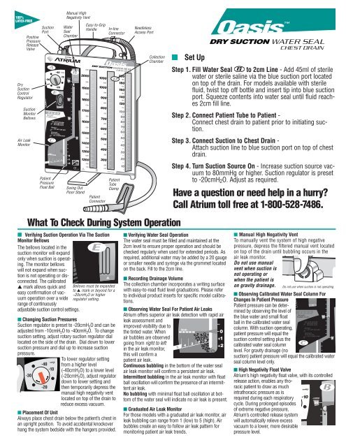
■ Verifying Suction Operation Via The Suction<br />
Monitor Bellows<br />
The bellows located in the<br />
suction monitor will expand<br />
only when suction is operating.<br />
The monitor bellows<br />
will not expand when suction<br />
is not operating or disconnected.<br />
The calibrated<br />
▲ mark allows quick and<br />
easy confir mation of vacuum<br />
operation over a wide<br />
range of continuously<br />
adjustable suction control settings.<br />
Bellows must be expanded<br />
to ▲ mark or beyond for a<br />
–20cmH 2 O or higher<br />
regulator setting.<br />
■ Changing Suction Pressures<br />
Suction regulator is preset to -20cmH 2 O and can be<br />
adjusted from -10cmH 2 O to -40cmH 2 O. To change<br />
suction setting, adjust rotary suction regulator dial<br />
located on the side of the drain. Dial down to lower<br />
suction pressure and dial up to increase suction<br />
pressure.<br />
To lower regulator setting<br />
from a higher level<br />
(-40cmH 2 O) to a lower level<br />
(-20cmH 2 O), adjust regulator<br />
down to lower setting and<br />
then temporarily depress the<br />
manual high negativity vent<br />
located on top of the drain to<br />
reduce excess vacuum.<br />
■ Placement Of Unit<br />
Always place chest drain below the patient’s chest in<br />
an upright position. To avoid accidental knockover<br />
hang the system bedside with the hangers provided.<br />
n<br />
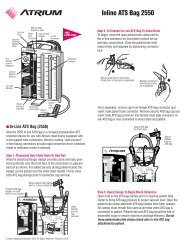
<strong>Set</strong> <strong>Up</strong><br />
Step 1. Fill Water Seal to 2cm Line - Add 45ml of sterile<br />
water or sterile saline via the blue suction port located<br />
on top of the drain. For models available with sterile<br />
fluid, twist top off bottle and insert tip into blue suction<br />
port. Squeeze contents into water seal until fluid reaches<br />
2cm fill line.<br />
Step 2. Connect Patient Tube to Patient -<br />
Connect chest drain to patient prior to initiating suction.<br />
Step 3. Connect Suction to Chest Drain -<br />
Attach suction line to blue suction port on top of chest<br />
drain.<br />
Step 4. Turn Suction Source On - Increase suction source vacuum<br />
to 80mmHg or higher. Suction regulator is preset<br />
to -20cmH 2 O. Adjust as required.<br />
Have a question or need help in a hurry<br />
Call <strong>Atrium</strong> toll free at 1-800-528-7486.<br />
■ Verifying Water Seal Operation<br />
The water seal must be filled and maintained at the<br />
2cm level to ensure proper operation and should be<br />
checked regularly when used for extended periods. As<br />
required, additional water may be added by a 20 gauge<br />
or smaller needle and syringe via the grommet located<br />
on the back. Fill to the 2cm line.<br />
■ Recording Drainage Volume<br />
The collection chamber incorporates a writing surface<br />
with easy-to-read fluid level graduations. Please refer<br />
to individual product inserts for specific model calibrations.<br />
■ Observing Water Seal For Patient Air Leaks<br />
<strong>Atrium</strong> offers superior air leak detection with rapid air<br />
leak assessment and<br />
improved visibility due to<br />
the tinted water. When<br />
air bubbles are observed<br />
going from right to left<br />
in the air leak monitor,<br />
this will confirm a<br />
patient air leak.<br />
Continuous bubbling in the bottom of the water seal<br />
air leak monitor will confirm a persistent air leak.<br />
Intermittent bubbling in the air leak monitor with float<br />
ball oscillation will confirm the presence of an intermittent<br />
air leak.<br />
No bubbling with minimal float ball oscillation at bottom<br />
of the water seal will indicate no air leak is present.<br />
■ Graduated Air Leak Monitor<br />
For those models with a graduated air leak monitor, air<br />
leak bubbling can range from 1 (low) to 5 (high). Air<br />
bubbles create an easy to follow air leak pattern for<br />
monitoring patient air leak trends.<br />
■ Manual High Negativity Vent<br />
To manually vent the system of high negative<br />
pressure, depress the filtered manual vent located<br />
on top of the drain until bubbling occurs in the<br />
air leak monitor.<br />
Do not use manual<br />
vent when suction is<br />
not operating or<br />
when the patient is<br />
on gravity drainage. Do not use when suction is not operating.<br />
■ Observing Calibrated Water Seal Column For<br />
Changes In Patient Pressure<br />
Patient pressure can be determined<br />
by observing the level of<br />
the blue water and small float<br />
ball in the calibrated water seal<br />
column. With suction operating,<br />
patient pressure will equal the<br />
suction control setting plus the<br />
calibrated water seal column<br />
level. For gravity drainage (no<br />
suction) patient pressure will equal the calibrated water<br />
seal column level only.<br />
■ High Negativity Float Valve<br />
<strong>Atrium</strong>’s high negativity float valve, with its controlled<br />
release action, enables any thoracic<br />
patient to draw as much<br />
intra thoracic pressure as is<br />
required during each respiratory<br />
cycle. During prolonged episodes<br />
of extreme negative pressure,<br />
<strong>Atrium</strong>’s controlled release system<br />
will automatically relieve excess<br />
vacuum to a lower, more desirable<br />
pressure level.
What To Check During System Operation<br />
■ Positive Pressure Protection<br />
<strong>Atrium</strong>’s positive pressure<br />
valve, located on<br />
top of drain, opens<br />
instantly to release<br />
accu mulated positive<br />
pressure. Do not<br />
obstruct the positive<br />
pressure valve.<br />
Troubleshooting<br />
Q<br />
How do I determine patient pressure with<br />
a dry suction chest drain<br />
Whether using a traditional wet or dry suction<br />
operating system, one cannot overem-<br />
A<br />
phasize the importance of the calibrated<br />
water seal column when it comes to diagnosing<br />
the patient’s condition or monitoring normal system<br />
operation. Patient pressure can be determined<br />
by observing the level of the blue water and small<br />
float ball in the calibrat ed water seal column. With<br />
suction operating and the bellows expanded<br />
across the suction monitor window, patient pressure<br />
will equal the suction control setting (read<br />
directly from the regulator dial) plus the calibrated<br />
water seal column level. For example, when the<br />
suction monitor bellows is expanded to the ▲<br />
mark or beyond to confirm a –20cmH 2 O suction<br />
setting, and the calibrated water seal column<br />
reads –15cmH 2 O, patient pressure is –35cmH 2 O<br />
(–20cmH 2 O + –15cmH 2 O = –35cmH 2 O). For gravity<br />
drainage (no suction) patient pressure will<br />
equal the calibrated water seal column only.<br />
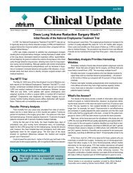
What should I do when the suction monitor<br />
bellows is not expanded to the ▲<br />
Q<br />
mark when the regulator is set at -20cmH 2 O or<br />
higher<br />
The position of the bellows across the suction<br />
monitor window will alert the operator<br />
A<br />
that the suction source has fallen below the<br />
minimum operating range for the prescribed suction<br />
control setting. Simply increase the vacuum<br />
source to –80mmHg or higher. The suction monitor<br />
bellows must expand to the ▲ mark or beyond for<br />
a –20cmH 2 O or higher suction regulator setting.<br />
Not enough vacu -<br />
um for -20cmH 2 O<br />
or higher suction<br />
control setting.<br />
Normal suction<br />
operation for<br />
-20cmH 2 O or<br />
higher.<br />
Increase suction<br />
source to -80mmHg<br />
or higher.<br />
Q<br />
■ Sampling Patient Drainage<br />
Sampling of patient drainage must be in accordance with approved hospital infection<br />
control standards. Selected models include a needleless luer port on the<br />
patient tube connector for sampling patient drainage. Alcohol swab the luer port<br />
prior to syringe attachment (no needle). Fluid samples can also be taken directly<br />
from the patient tube by forming a temporary dependent loop and inserting a 20<br />
gauge needle at an oblique angle. Alcohol swab the patient tube prior to inserting<br />
syringe at a shallow angle. Do not puncture patient tube with an 18 gauge or<br />
larger needle.<br />
■ System Disconnection<br />
For models equipped with an in-line connector, close the patient tubeslideclamp<br />
prior todisconnecting the chest drain patient tube from patient. Clamp off all<br />
indwelling thoracic catheters prior to disconnecting chest drain from patient.<br />
What should I do when the bellows<br />
does not fully expand to the ▲ mark<br />
after I increase the suction source vacuum<br />
A<br />
Dry suction chest drains require higher<br />
levels of vacuum pressure and air flow<br />
from the suction source to operate efficiently<br />
at each suction control setting as compared<br />
to traditional water controlled operating<br />
systems. The suction source should provide a<br />
minimum vacuum pressure of –80mmHg at 20<br />
liters of air flow per minute for chest drain operating<br />
efficiency at a suction control setting of<br />
–20cmH 2 O. The suction source should be<br />
greater than –80mmHg when multiple chest<br />
drains are connected to a single suction source.<br />
If the bellows does not fully expand to the ▲<br />
mark, it may simply be that the suction source<br />
is not functioning to its full potential to provide<br />
the minimum vacuum pressure or air flow<br />
required to “drive” the suction control regulator.<br />
Additionally, conditions may exist that can<br />
reduce, or “restrict” air flow from the suction<br />
source. A restrictive clamp, connector, or kink<br />
in the suction line tubing can potentially<br />
“starve” the chest drain of air flow. A leak in a<br />
connection or wall canister, along with extensive<br />
lengths of suction tubing can also reduce<br />
air flow to the unit.<br />
To troubleshoot this situation, first check to be<br />
sure that all connections are air-tight. Inspect<br />
the suction tubing and connections for possible<br />
cracks, leaks, kinks, or occlusion. You may<br />
need to simply bypass a “leaky” wall canister.<br />
Try connecting the chest drain to a different<br />
suction source or wall regulator. When multiple<br />
chest drains are “Y” connected to a single suction<br />
source, if possible, reconnect the drains to<br />
separate suction sources. Finally, replace the<br />
chest drain if you suspect the unit is cracked or<br />
damaged.<br />
Does the bellows need to expand<br />
Q beyond the ▲ mark for a –10cmH 2 O<br />
regulator setting<br />
No. For a regulator setting less than<br />
A –20cmH 2 O suction (–10cmH 2 O), any<br />
observed bellows expansion across the<br />
monitor window will confirm suction operation.<br />
The bellows need not be expanded to the ▲<br />
mark for suction pressures less than<br />
–20cmH 2 O, just visibly expanded to confirm<br />
suction operation.<br />
How do I confirm my patient has an<br />
Q air leak when there is:<br />
■ No bubbling in the water seal<br />
If there are no air bubbles observed<br />
A going from right to left in the air leak<br />
monitor, there is no patient air leak. In<br />
order to confirm that your patient’s chest<br />
catheter is patent, temporarily turn suction off<br />
and check for oscillation of the patient pressure<br />
float ball in the water seal column coinciding<br />
with patient respiration.<br />
■ Bubbling present in the water seal<br />
Whenever constant or intermittent bubbling<br />
is present in the water seal air<br />
A<br />
leak monitor, this will confirm an air<br />
leak is present. Oscillation of the patient pressure<br />
float ball at the bottom of the water seal<br />
without bubbling will indicate no apparent air<br />
leak. Bubbling from right to left must be present<br />
to confirm an air leak. To determine the<br />
source of the air leak (patient or catheter connection),<br />
momentarily clamp the patient tube<br />
close to the chest drain and observe the water<br />
seal. If bubbling stops, the air leak may be<br />
from the catheter connections or the patient’s<br />
chest. Check the cathe ter connectors and<br />
patient dressing for a partially withdrawn<br />
catheter. If bubbling continues after temporarily<br />
clamping the patient tube, this will indicate<br />
a system air leak requiring system replacement.<br />
www.atriummed.com<br />
© <strong>Atrium</strong> <strong>Medical</strong> <strong>Corporation</strong> 2010 All Rights Reserved 10/10 Part #0044C