Grounding, Lightning Protection and Surge Protection
Grounding, Lightning Protection and Surge Protection
Grounding, Lightning Protection and Surge Protection

Create successful ePaper yourself
Turn your PDF publications into a flip-book with our unique Google optimized e-Paper software.
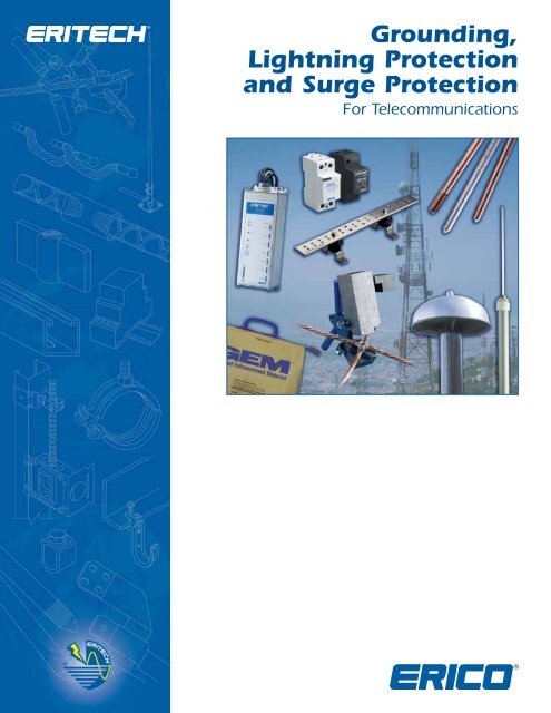
<strong>Grounding</strong>,<br />
<strong>Lightning</strong> <strong>Protection</strong><br />
<strong>and</strong> <strong>Surge</strong> <strong>Protection</strong><br />
For Telecommunications
Indoor Bonding Layout<br />
<strong>Grounding</strong>/earthing, lightning protection <strong>and</strong> surge protection<br />
are critical parts of a telecommunications facility installation.<br />
ERICO ® has complete telecommunications applications solutions<br />
to help protect the facility against electrical noise, lightning<br />
induced surges <strong>and</strong> transients caused by switching components<br />
in the power systems.<br />
ERICO solutions include ERITECH ® ground rods, ground mats,<br />
ground enhancing material (GEM), ground bars, CADWELD ®<br />
connections, ERITECH lightning protection systems <strong>and</strong> CRITEC ®<br />
MDF, co-axial <strong>and</strong> power surge protectors.<br />
To make the application of these products simpler, the<br />
grounding, lightning protection <strong>and</strong> surge protection system<br />
at a telecommunications facility is divided into 5 components.<br />
1. Indoor Bonding Arrangement<br />
2. Outdoor <strong>Grounding</strong> Arrangement<br />
3. <strong>Surge</strong> <strong>Protection</strong> for Power Lines<br />
4. <strong>Surge</strong> <strong>Protection</strong> for Telephone Lines<br />
5. Direct Strike <strong>Lightning</strong> <strong>Protection</strong><br />
ERITECH ground bars can be used to achieve the ideal indoor<br />
grounding arrangement as required at the telecommunications<br />
facility.<br />
<strong>Surge</strong> <strong>Protection</strong><br />
A<br />
B<br />
D<br />
E<br />
F<br />
LEGEND<br />
C<br />
A<br />
B<br />
C<br />
D<br />
E<br />
F<br />
Main Ground Bar<br />
Bonding Terminal or Isolated Spark<br />
Gap (optional)<br />
Telecommunications Ground Electrode<br />
AC Ground Electrode<br />
Communications Ground Bar<br />
Battery Ground<br />
2<br />
www.erico.com
Outdoor <strong>Grounding</strong> / Earthing Layout<br />
The outdoor arrangement of a grounding system at a<br />
telecommunications facility is depicted here. This arrangement is<br />
not always possible due to certain constraints at the site. Where<br />
the telecommunication equipment is installed in a large multi<br />
functional building or several floors above the ground floor this<br />
layout may not be possible.<br />
Alternative outdoor ground electrode system needs to be<br />
considered on a case by case basis if the suggested layout<br />
below is not possible to implement.<br />
ERICO ® offers a full range of products to form the outdoor<br />
grounding system at a telecommunications facility.<br />
A<br />
E<br />
D<br />
F<br />
E<br />
B<br />
C<br />
LEGEND<br />
A<br />
B<br />
C<br />
D<br />
E<br />
F<br />
Telecommunication ground electrode system<br />
Vertical ground electrodes<br />
Tower ground<br />
Coaxial <strong>and</strong> Waveguide feeders<br />
Coaxial surge protectors or ground kit<br />
RF Ground Bar<br />
www.erico.com 3
ERITECH ® Ground Rods, Connections <strong>and</strong> Accessories<br />
ERITECH ® Ground Rods<br />
ERICO ® offers a range of ground rods for telecommunications<br />
applications to suit the needs <strong>and</strong> preferences of the carriers. The most<br />
common of these are copper bonded steel ground rods, due to their<br />
versatility in varied soil conditions <strong>and</strong> compatibility with various common<br />
metals used underground.<br />
The copper-bonded ground rod has an electrolytic coating of copper<br />
deposited over a layer of nickel. This process helps ensure a long lasting,<br />
molecular bond between the copper layer <strong>and</strong> the steel core. ERICO<br />
recommends copper-bonded ground rods because the copper coating<br />
will not slip or tear when driven, nor will it crack if the rod is bent. The<br />
tough, carbon steel core has good characteristics for deep driving.<br />
Copper-bonded ground rods have a high resistance to corrosion <strong>and</strong><br />
provide a low resistance path to ground.<br />
It is important to note that certain soils <strong>and</strong> l<strong>and</strong>fill areas may not be<br />
compatible with copper. In these situations, stainless steel is a better<br />
choice. Stainless steel may also be an alternative, when structures or<br />
components, such as steel towers, poles or lead sheathed cables are in<br />
close proximity to an array of ground electrodes. In these circumstances,<br />
consideration must be given to the consequence of galvanic corrosion.<br />
<strong>Grounding</strong> Connections<br />
<strong>Grounding</strong> connections are vital to the proper operation <strong>and</strong> integrity<br />
of the electrical system. ERICO offers a range of mechanical grounding<br />
connections including clamps, jumpers, fence connections, U-Bolts <strong>and</strong><br />
other clamps.<br />
However, the CADWELD ® welded electrical connection is our<br />
recommended method of making grounding connections. The principle<br />
technology consists of bringing together a welding material <strong>and</strong> ignition<br />
agent in a suitable graphite mold. The reduction of copper oxide by<br />
aluminum produces molten copper <strong>and</strong> aluminum oxide slag at extremely<br />
high temperatures. The shape of the mold, its dimensions, <strong>and</strong> the size<br />
of welding material, are all dependent on the items to be welded.<br />
1 2<br />
3<br />
4<br />
The key benefits of CADWELD are:<br />
• Connections are permanent <strong>and</strong> will not loosen or corrode.<br />
• Connections are made with inexpensive, lightweight equipment.<br />
• Connections can be made without the need for any special skills.<br />
The CADWELD connection is essentially a fusing through of the<br />
grounding conductor, whereby there is greater amount of metal across<br />
the cross section of the connection than that across the conductor. It can<br />
be intuitively seen that the connection is as good as the conductor, if not<br />
better, which is a unique feature of CADWELD. Independent scientific<br />
tests have been done to CADWELD using the most stringent st<strong>and</strong>ards<br />
associated with high voltage electrical installations.<br />
TA<br />
BM<br />
Typical CADWELD Connections used in telecommunications<br />
grounding <strong>and</strong> bonding<br />
Ground Bar<br />
Ground Clamp<br />
Ground Clamp<br />
PT<br />
LJ<br />
Earth Tester<br />
<strong>Grounding</strong> Conductors <strong>and</strong> Accessories<br />
The two most common grounding conductors used in telecommunications<br />
are round cables or flat tape. Flat tape conductors have a lower<br />
inductance <strong>and</strong> provide a higher capacitive coupling to the ground,<br />
which results in a lower impedance earth system, especially at high<br />
frequencies associated with lightning <strong>and</strong> telecommunications noise.<br />
ERICO offers a range of conductors including bare or tinned copper tape,<br />
bare copper cables <strong>and</strong> smooth weave cable conductors.<br />
In situations where ground conditions make it difficult to achieve the<br />
required resistance, ERICO offers Ground Enhancement Material (GEM).<br />
GEM is a low-resistance, non-corrosive, carbon dust based material that<br />
improves grounding effectiveness, especially in areas of poor conductivity.<br />
GEM contains cement, which hardens when set to provide a permanent,<br />
maintenance-free, low-resistant grounding system that will not<br />
leach or wash away.<br />
ERICO also provides a range of coaxial surge protectors that are suitable<br />
for use up to a frequency of 3 GHz. It is strongly recommended that<br />
feeders not fitted with coaxial surge protectors be grounded via<br />
appropriate grounding kits.<br />
The ERITECH EST series of earth testers are available for testing of soil<br />
resistivity <strong>and</strong> ground resistance of electrodes.<br />
GL<br />
VS<br />
GY<br />
LQ<br />
4<br />
www.erico.com
<strong>Surge</strong> <strong>Protection</strong> for Power <strong>and</strong> Telephone Lines<br />
A telecommunications site needs reliable grounding for the purpose of<br />
good reference ground, noise control <strong>and</strong> dissipation of any lightning<br />
energy. <strong>Surge</strong>s in the power <strong>and</strong> copper based telephone lines can also<br />
originate from lightning strikes that have struck objects some distance<br />
from the actual site, in many cases, even miles away. Having a good<br />
ground alone is not enough to minimize damage due to these surges<br />
caused by distant strikes. <strong>Surge</strong>s can also occur in power lines due to<br />
switching of circuit breakers in the power systems under fault conditions.<br />
It is important to have adequate surge protection on the AC mains <strong>and</strong><br />
on telephone lines.<br />
The best starting point in the selection of surge protection devices is to<br />
look at the following 5 ratings as defined by IEC ® st<strong>and</strong>ards <strong>and</strong> choose<br />
suitable levels for the application.<br />
• Maximum Discharge Current, or Imax. This is the single shot rating<br />
of the SPD.<br />
• Nominal Discharge Current or In. This is the 15 shot rating of the SPD.<br />
• Voltage <strong>Protection</strong> Level, or Up. This is the voltage to which surges<br />
tested to IEC st<strong>and</strong>ards are limited to. Normally this test is done at In.<br />
Sometimes this test is done at 3kA 8/20us. The lower the Up the<br />
better the SPD is as a protection device.<br />
• Maximum Continuous Operating Voltage, or Uc. SPD’s can experience<br />
damage if the supply voltage exceeds their clamp voltage for a<br />
prolonged duration. A high Uc will mean that the product is rugged<br />
against over-voltage events.<br />
Typical Wiring of a SPD at a Main Switch Board<br />
Mains Supply<br />
SPD<br />
SPD<br />
Various<br />
Loads<br />
CB or Fuse<br />
Neutral<br />
Ground<br />
The SPD arrangement shown left is called shunt surge protection whereby the SPD is<br />
connected in parallel with the load. The limitation of this type of protection is that while<br />
the surge voltage is controlled to a manageable level, these devices do not lower the<br />
voltage rise time of the incoming surges. It is widely acknowledged that both the voltage<br />
level as well as the rise time of power surges can cause damage to sensitive electronics.<br />
In applications where a higher level of protection is deemed necessary due to the critical<br />
nature of the telecommunications network element, surge reduction filters can be used to<br />
effectively reduce the voltage levels <strong>and</strong> rise times.<br />
<strong>Surge</strong> <strong>Protection</strong> for Telephone Lines<br />
<strong>Lightning</strong> surges can get coupled into telephone lines, in a very<br />
similar manner that they couple into power lines.<br />
A single stage gas arrestor installed at the main distribution frame helps<br />
ensure that both of the lines are shorted to ground momentarily to take<br />
bulk of the energy down to ground when a surge occurs. However, because<br />
it is not possible to short out the two lines at exactly the same moment, a<br />
differential mode transient develops which is very damaging to the end<br />
equipment. Hence in critical applications, the use of single stage gas arrester<br />
modules at main distribution frame is not adequate. <strong>Surge</strong> protective devices<br />
with secondary clamping stages provide a better protection.<br />
Topologies for Telephone Line <strong>Protection</strong><br />
www.erico.com 5
<strong>Lightning</strong> <strong>Protection</strong> for Telecommunications Towers<br />
Direct lightning strikes to telecommunications towers are a<br />
reasonably regular occurrence, more so on mountain tops<br />
<strong>and</strong> in certain parts of the world. The traditional approach<br />
to lightning protection on towers is to have a lightning rod<br />
on the top of the tower <strong>and</strong> a dedicated down conductor<br />
comprised of bare cable or tape that is installed on the<br />
tower to connect the lightning rod to the ground.<br />
A modern method is to use an optimal air terminal design,<br />
the ERITECH ® DYNASPHERE mounted on top of the<br />
telecommunications mast on a 3-4 metres long fibreglass<br />
reinforced pole, FRP. The FRP provides isolation between the<br />
air terminal <strong>and</strong> the tower <strong>and</strong> helps ensure that the<br />
lightning does not flash over <strong>and</strong> electrify the mast or the<br />
antenna. A special purpose downconductor, called the<br />
ERITECH ® ERICORE is routed in the core of the FRP <strong>and</strong><br />
connects to the bottom of the ERITECH ® DYNASPHERE via<br />
a high voltage, impulse rated termination. The ERITECH ®<br />
ERICORE runs along a leg of the tower away from the routes<br />
of feeders, down to the tower grounding system. ERITECH ®<br />
ERICORE cable is designed to minimize the voltage between<br />
itself <strong>and</strong> the tower so that the bulk of the lightning energy<br />
is contained within the cable, thereby protecting the tower<br />
<strong>and</strong> feeders from conducted lightning currents <strong>and</strong> having<br />
much less reliance on bonding practices which sometimes<br />
are overlooked or completed incorrectly.<br />
ERITECH ®<br />
DYNASPHERE<br />
Conventional /<br />
ISODC*<br />
OR<br />
ERITECH ®<br />
ERICORE<br />
ISODC*<br />
Conventional Cable<br />
Smoothweave<br />
OR<br />
OR<br />
* ISODC - is an isolated lightning protection cable system based around IEC62305. It is designed to isolate the lightning current from<br />
sensitive equipment, eliminating the need for separation distances required with conventional cable. Contact ERICO ® for further information.<br />
6<br />
www.erico.com
<strong>Lightning</strong> <strong>Protection</strong> for Roof Mounted Installations<br />
Traditionally, some rooftop installation have been protected<br />
by the use of air terminals (Franklin <strong>Lightning</strong> Rods), often<br />
connected to the building lightning protection system.<br />
However, the traditional building lightning protection<br />
techniques are not well suited to protect these roof<br />
top installations. Hence many telecommunications<br />
companies have opted not to provide any form of air<br />
terminal. Instead they do extensive bonding of all their<br />
roof mounted equipment.<br />
Method 1: Isolated downconductor<br />
connected to lightning<br />
protection<br />
Fiberglass<br />
reinforced pole<br />
Air<br />
Terminal<br />
The ERITECH ® Isolated Downconductor System provides a<br />
modern approach to lightning protection for rooftop<br />
installations. The ERITECH isolated system provides a<br />
traditional air terminal fitted to an isolated fiberglass<br />
reinforced plastic (FRP) mast. The isolated downconductor<br />
internally connects to the air terminal inside the FRP. The FRP<br />
mast has natural isolation properties, high strength for windy<br />
sites <strong>and</strong> low weight to minimize mast loading.<br />
The advantage is that this downconductor can be mounted<br />
directly on the mast or structure to be protected – without<br />
electrification of mounted equipment under lightning<br />
conditions.<br />
Isolated<br />
Downconductor<br />
Air<br />
Terminal<br />
Fiberglass<br />
reinforced pole<br />
Connects to <strong>Lightning</strong><br />
<strong>Protection</strong> System<br />
Communications<br />
Shelter<br />
Lift<br />
Room<br />
RF Feeders<br />
RF Antenna<br />
Parapet<br />
Microwave<br />
Antenna<br />
Telecommunications<br />
Main Ground Bar<br />
Bond Ground Bar to<br />
<strong>Lightning</strong> <strong>Protection</strong><br />
Method 2: Bonding method<br />
of protection<br />
RF Antenna<br />
<strong>Lightning</strong> <strong>Protection</strong><br />
Ground Bar<br />
Main Ground Bar<br />
Bonding Wire<br />
RF Antenna<br />
Earth Electrode<br />
<strong>Lightning</strong> <strong>Protection</strong><br />
Ground Bar<br />
www.erico.com 7
www.erico.com<br />
AUSTRALIA<br />
6 Chilvers Road<br />
P.O. Box 148<br />
Thornleigh (Sydney) NSW 2120<br />
Australia<br />
Phone 61-2-9479-8500<br />
Fax 61-2-9484-9188<br />
GERMANY<br />
66851 Schwanenmühle<br />
Germany<br />
Phone 49-6307-918-10<br />
Fax 49-6307-918-150<br />
POLAND<br />
ul. Krzemieniecka 17<br />
54-613 Wroclaw<br />
Pol<strong>and</strong><br />
Phone 48-71-374-40-22<br />
Fax 48-71-374-40-43<br />
BELGIUM<br />
Postbus 33<br />
3110 Rotselaar<br />
Belgium<br />
Phone 32-14-69-96-88<br />
Fax 32-14-69-96-90<br />
BRAZIL<br />
R. Dom Pedro Henrique de Orleans<br />
E Braganca, 276<br />
Vila Jaguara<br />
São Paulo CEP 05117-000<br />
Brazil<br />
Phone 55-11-3621-4111<br />
Fax 55-11-3621-4066<br />
CANADA<br />
P.O. Box 170<br />
Mississauga, Ontario<br />
Canada L5M 2B8<br />
Phone 1-800-677-9089<br />
Fax 1-800-677-8131<br />
CHILE<br />
Alcantara 200, piso 6 Of. 17<br />
Las Condes, Santiago<br />
Chile<br />
Phone 56-2-370-2908<br />
Fax 56-2-370-2914<br />
HONG KONG<br />
Unit 1, 2nd Floor, Block A<br />
Po Yip Building<br />
62-70 Texaco Road<br />
Tsuen Wan, New Territories<br />
Hong Kong<br />
Phone 852-2764-8808<br />
Fax 852-2764-4486<br />
HUNGARY<br />
P.f. 184<br />
1476 Budapest<br />
Hungary<br />
Phone 31-13-58-34-547<br />
Fax 31-13-58-35-499<br />
INDONESIA<br />
Sampoerna Strategic Square,<br />
Tower B 19th Fl.<br />
Jalan Jend. Sudirman Kav. 45-46<br />
Jakarta 12930<br />
Indonesia<br />
Phone 62-21-575-0941<br />
Fax 62-21-575-0942<br />
ITALY<br />
A&B Business Center<br />
Via Valla 16, nr. 17<br />
20141 Milano<br />
Italy<br />
Phone 39-02-8474-2250<br />
Fax 39-02-8474-2251<br />
SINGAPORE<br />
Jurong Industrial Estate<br />
16 Wan Lee Road<br />
Singapore 627 946<br />
Phone 65-6-268-3433<br />
Fax 65-6-268-1389<br />
SPAIN<br />
C/Provenza 288, Pral.<br />
08008 Barcelona<br />
Spain<br />
Phone 34-93-467-7726<br />
Fax 34-93-467-7725<br />
SWEDEN<br />
Box 211<br />
201 22 Malmö<br />
Sweden<br />
Phone 46-40-611-13-60<br />
Fax 46-40-611-94-15<br />
SWITZERLAND<br />
Postfach 54<br />
3280 Murten<br />
Switzerl<strong>and</strong><br />
Phone 00-800-5000-1090<br />
Fax 00-800-6000-1090<br />
CHINA<br />
Room 1204<br />
Tomson Commercial Building<br />
No. 710 Dongfang Road<br />
Pudong, Shanghai<br />
P.R. China 200122<br />
Phone 86-21-5081-3900<br />
Fax 86-21-5831-8177<br />
DENMARK<br />
Box 211<br />
201 22 Malmö<br />
Sweden<br />
Phone 46-40-611-13-60<br />
Fax 46-40-611-94-15<br />
MEXICO<br />
Melchor Ocampo 193<br />
Torre A piso 13<br />
Col. Veronica Anzures<br />
11300 Mexico D.F.<br />
Mexico<br />
Phone 52-55-5260-5991<br />
Fax 52-55-5260-3310<br />
NETHERLANDS<br />
Jules Verneweg 75<br />
5015 BG Tilburg<br />
Netherl<strong>and</strong>s<br />
Phone 31-13-58-35-400<br />
Fax 31-13-58-35-499<br />
THAILAND<br />
163 Ocean Insurance Bldg.<br />
16th Fl. Unit B<br />
Surawongse Road<br />
Bangrak Bangkok 10500<br />
Thail<strong>and</strong><br />
Phone 66-2-634-1692<br />
Fax 66-2-634-1694<br />
UNITED KINGDOM<br />
52 Milford Road<br />
Reading, Berkshire RG1 8LJ<br />
United Kingdom<br />
Phone 44-118-955-0900<br />
Fax 44-118-955-0925<br />
FRANCE<br />
rue Charles Dallière, BP 31<br />
42161 Andrezieux Bouthéon Cedex<br />
France<br />
Phone 33-4-77-36-54-32<br />
Fax 33-4-77-55-20-10<br />
NORWAY<br />
Postboks 148<br />
1366 Lysaker<br />
Norway<br />
Phone 47-67-53-12-00<br />
Fax 47-67-12-42-68<br />
UNITED STATES<br />
34600 Solon Road<br />
Solon, Ohio 44139<br />
U.S.A.<br />
Phone 1-440-248-0100<br />
Fax 1-440-248-0723<br />
IEC is a registered service mark of Independent Electrical Contractors, Inc.<br />
Copyright ©2007 ERICO International Corporation. All rights reserved.<br />
CADDY, CADWELD, CRITEC, ERICO, ERIFLEX, ERITECH, <strong>and</strong> LENTON are registered trademarks of ERICO International Corporation.<br />
E656B-WWEN E190LT07WWEN 00820M7