


You also want an ePaper? Increase the reach of your titles
YUMPU automatically turns print PDFs into web optimized ePapers that Google loves.
LNG Shipping at 50|the early years<br />
membrane tank system for LNG<br />
carriers. The system was based on the<br />
semi-membrane design as installed on<br />
the 72,344m 3 LPG carrier Bridgestone<br />
Maru No 5, which had been delivered<br />
by Kawasaki Heavy Industries in<br />
September that year.<br />
Compared to the LPGC<br />
arrangement, with tanks in pairs, the<br />
LNG design proposed cargo tanks<br />
extending across the full beam of the<br />
ship. Depending on the design of the<br />
ship, the ‘metal’ membrane primary<br />
barrier was to have a thickness in the<br />
3-10mm range. The flat walls were<br />
supported by load-bearing insulation<br />
on the hull structure, with cylindrical<br />
edges and large ball corners to allow<br />
for thermal expansion and contraction.<br />
The secondary barrier was coated<br />
plywood panels.<br />
To be assembled separately before<br />
being lifted into the ship’s hold<br />
spaces, the tanks would be held<br />
in position at the tank dome by a<br />
large hanger system. The lifting of a<br />
completed tank would necessitate a<br />
temporary internal frame support for<br />
the unstiffened membrane.<br />
Dytam Tanker GmbH began research<br />
into the use of reinforced concrete for<br />
cryogenic applications in August 1972.<br />
Based in Kiel, Germany, Dytam was<br />
a joint venture between Dyckerhoff<br />
and Widmann, a concrete firm, and<br />
Tampimex, an oil trader.<br />
Dytam developed a design for a<br />
concrete 128,000m 3 LNG carrier. The<br />
290m long vessel had a single hull<br />
made from concrete and 10 cargo tanks<br />
arranged in pairs. Internal insulation<br />
was either sprayed on or enclosed in<br />
stud-mounted fibreglass panels. The<br />
transverse bulkheads were dished<br />
in shape to allow for expansion and<br />
contraction. The thickness of the<br />
concrete was 60cm at the bottom hull,<br />
45cm at the side hull and 20cm at<br />
centre. The concrete was reinforced<br />
longitudinally and transversely by<br />
stressed and unstressed steel rods.<br />
As a solution for developing the<br />
remote Arctic gas fields Boeing of<br />
Seattle proposed a unique air and sea<br />
LNG solution in 1974. A fleet of up to<br />
14 Boeing 747 freighters were to fly<br />
planeloads of LNG south to a marine<br />
terminal on the US Pacific coast for the<br />
onwards sea leg of this LNG distribution<br />
chain. Each aircraft would be capable<br />
of carrying up to 350m 3 of LNG over a<br />
distance of 1,100km.<br />
In 1976 Owens-Corning Fiberglas<br />
of Toledo, Ohio introduced an internal<br />
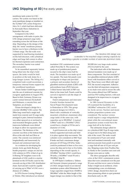
The Verolme LNG design was<br />
scaleable to the required cargo-carrying capacity by<br />
specifying a greater or smaller number of same-size aluminium tanks<br />
insulation LNG containment system<br />
called Perm-Bar II. The system was<br />
made up of prefabricated panels<br />
secured to the ship’s inner hull by<br />
studs. The insulation was made up of<br />
two panels. The main flat panels were<br />
rectangular in shape and provided<br />
a primary and secondary barrier of<br />
glassfibre-reinforced plastic (GRP) with<br />
polyurethane foam (PUF) between.<br />
A third barrier labyrinth of FRP was<br />
fitted at the inner hull. Panels could be<br />
curved or tapered to suit the shape of<br />
the cargo tank.<br />
Dutch entrepreneur and innovator<br />
Cornelis Verolme formed his<br />
Naval Project Development team<br />
in Rotterdam in 1976. This group<br />
produced designs for LNGCs,<br />
fitted with a multitude of vertically<br />
mounted, cylindrical, aluminium alloy<br />
cargo tanks of the same size, with<br />
capacities up to 500,000m 3 . A typical<br />
3,500m 3 tank for a 330,000m 3 LNGC<br />
would have a height of 35.5m and a<br />
diameter of 11.8m.<br />
A grid framework on the ship’s inner<br />
bottom supported each tank and held<br />
it in place against ship movements. The<br />
cylinders were considered as IMO Type<br />
B tanks and had a maximum design<br />
pressure of 0.35 barg (135 kPa). Tanks<br />
could be positioned in three or five rows<br />
across the ship and in four or five holds,<br />
depending on the overall capacity. A<br />
125,000m 3 Verolme LNGC would have<br />
38 tanks, a 165,000m 3 vessel 50 and a<br />
330,000m 3 ship 93.<br />
In 1978 Spain’s Astilleros y Talleres<br />
del Noroeste (Astano) proposed a range<br />
of LNGC designs based on an internal<br />
insulation system called Metastano 20.<br />
Cargo capacities ranged from 130,000 to<br />
300,000m 3 while the 366m length of the<br />
largest design was similar to that of the<br />
363,000 dwt very large crude carriers<br />
(VLCCs) built by the yard.<br />
The individual cells of the Metastano<br />
internal insulation were made up of<br />
three components. The first consisted of<br />
two glassfibre-reinforced plastic (GRP)<br />
boxes with boundaries either curved or<br />
flat. These boxes were filled with rigid<br />
PUF, the second component. Adhesive<br />
was the third all-important component,<br />
as no studs were used to secure the cells.<br />
The system offered four GRP barriers<br />
and four PUF sealing barriers, with each<br />
designed to be impervious to cryogenic<br />
liquid leakage.<br />
In 1981 General Dynamics in the<br />
US examined the feasibility of a<br />
140,000m 3 submarine LNG carrier<br />
for Arctic service. Nuclear and steam<br />
turbine propulsion systems were<br />
considered. The nuclear version<br />
would require a cargo reliquefaction<br />
plant while the conventional steam<br />
propulsion system would burn the<br />
cargo boil-off in the boilers.<br />
The submarine design called for<br />
six cylindrical IMO Type B cargo tanks<br />
of equal size to be fitted along each<br />
side of the vessel. The tanks would<br />
be constructed of 9 per cent nickel<br />
steel and insulated externally with<br />
polyisocyanurate foam panels to provide<br />
a cargo boil-off rate of 0.2 per cent per<br />
day. Shipping routes from Prudhoe Bay<br />
in Alaska to the Canadian east coast and<br />
Europe were seen as viable.<br />
The above paragraphs describe only<br />
a few of the LNGC containment system<br />
ideas that were considered over the past<br />
50 years and that never came to fruition.<br />
Today’s bright naval architects, when<br />
contemplating a new revolutionary<br />
LNGC design, should first check out<br />
these pioneering efforts to spot potential<br />
drawbacks early on. SH<br />
32 I LNG shipping at 50<br />
A SIGTTO/GIIGNL commemorative issue