Simple machines
Simple machines
Simple machines

You also want an ePaper? Increase the reach of your titles
YUMPU automatically turns print PDFs into web optimized ePapers that Google loves.
<strong>Simple</strong> <strong>machines</strong><br />
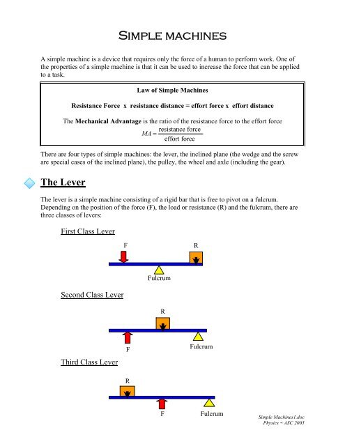
A simple machine is a device that requires only the force of a human to perform work. One of<br />
the properties of a simple machine is that it can be used to increase the force that can be applied<br />
to a task.<br />
Law of <strong>Simple</strong> Machines<br />
Resistance Force x resistance distance = effort force x effort distance<br />
The Mechanical Advantage is the ratio of the resistance force to the effort force<br />
resistance force<br />
MA =<br />
effort force<br />
There are four types of simple <strong>machines</strong>: the lever, the inclined plane (the wedge and the screw<br />
are special cases of the inclined plane), the pulley, the wheel and axle (including the gear).<br />
The Lever<br />
The lever is a simple machine consisting of a rigid bar that is free to pivot on a fulcrum.<br />
Depending on the position of the force (F), the load or resistance (R) and the fulcrum, there are<br />
three classes of levers:<br />
First Class Lever<br />
F<br />
R<br />
Fulcrum<br />
Second Class Lever<br />
R<br />
Third Class Lever<br />
F<br />
Fulcrum<br />
R<br />
F<br />
Fulcrum<br />
<strong>Simple</strong> Machines1.doc<br />
Physics ~ ASC 2005
First Class Level<br />
Force<br />
F<br />
⋅ d<br />
= R ⋅<br />
1<br />
d 2<br />
(*)<br />
Fulcrum<br />
d<br />
d<br />
1<br />
2<br />
R<br />
F<br />
=<br />
d<br />
d<br />
1<br />
2<br />
=<br />
MA pulley<br />
The fulcrum is between the force and the load. This is the most common arrangement. The<br />
mechanical advantage of this lever depends upon where we place the fulcrum. If the fulcrum is<br />
closer to the load, the mechanical advantage is higher.<br />
Examples of this class are the seesaw, the rows in a boat, etc.<br />
Second Class Level<br />
Force<br />
d<br />
1<br />
Fulcrum<br />
d<br />
2<br />
R<br />
F<br />
F ⋅ d<br />
d<br />
=<br />
d<br />
1<br />
d 2<br />
1<br />
2<br />
= R ⋅<br />
=<br />
MA pulley<br />
(*)<br />
Here the load ( R ) is between the force and the fulcrum. The mechanical advantage of this type<br />
of lever depends upon the placement of the load. It is greater when the load is closer to the<br />
fulcrum. When the load is closer to the force, the mechanical advantage approaches to one, so no<br />
mechanical advantage at all.<br />
R<br />
MA pulley<br />
= = 1 ⇒ R = F<br />
F<br />
Examples of this class are: the wheelbarrow, the stapler, the nutcracker, etc<br />
(*) Notice that the distance is always measured from the force (or load) to the fulcrum no matter where it<br />
is located.<br />
- 2 -<br />
<strong>Simple</strong> Machines1.doc<br />
Physics ~ ASC 2005
Third Class Level<br />
Load ( R )<br />
2<br />
Fulcrum<br />
Force<br />
R d<br />
d<br />
1<br />
1<br />
= = MA pulley<br />
d<br />
F d<br />
2<br />
2<br />
Load(R)<br />
Force<br />
Load<br />
Distance<br />
Force Distance<br />
d d 2 1<br />
In this class the force is between the fulcrum and the load (R ). The human forearm is a third<br />
class lever. The elbow is the fulcrum, and the forearm muscles apply the effort between the<br />
elbow and hand. Tweezers, tongs, and the fishing rod are examples of this type. Levers of this<br />
class are used less often because their mechanical advantage is less than one; this means that the<br />
force needed to use them is greater than the force they can move.<br />
The Inclined Plane<br />
F ⋅ d<br />
= R ⋅<br />
1<br />
d 2<br />
lenght of<br />
=<br />
height of<br />
plane<br />
=<br />
plane<br />
MA inclined plane<br />
The inclined plane is a simple machine, consisting of a sloping surface, which has some angle<br />
above or below the horizontal used to raise objects that are too heavy to lift vertically.<br />
Gangways, chutes, and ramps are all examples of the inclined plane.<br />
Switchbacks on mountain roads are also examples of inclined planes that reduce the effort of an<br />
automobile engine but increase the distance a car must travel to ascend the mountain.<br />
R<br />
F<br />
F ⋅ d<br />
1<br />
= R ⋅ d<br />
The inclined plane has been modified in many ways. The screw and wedge are applications<br />
of the principle behind the inclined plane but do not require that the load be moved vertically<br />
for their successful operation.<br />
• The screw consists essentially of a solid cylinder, usually of metal, around which<br />
an inclined plane winds spirally, either clockwise or counterclockwise. It is used<br />
- 3 -<br />
<strong>Simple</strong> Machines1.doc<br />
Physics ~ ASC 2005
to fasten one object to another, to lift a heavy object, or to move an object by a<br />
precise amount.<br />
• The wedge shape has a triangular cross-section. It may be used to lever, split, or<br />
tighten.<br />
The Pulley<br />
The pulley is a simple machine, consisting of a wheel that rotates around a stationary axle. The<br />
outer rim of the pulley is grooved to accommodate a rope or chain. Pulleys are used for lifting by<br />
attaching one end of the rope to the object, threading the rope through the pulley (or system of<br />
pulleys), and pulling on the other end of the rope.<br />
A single, fixed pulley just changes the direction of the applied force and make it easier to lift the<br />
load, since a person can pull down on a rope, rather than simply lifting the load. A common<br />
example of a pulley can be found at the top of a flagpole. .<br />
Pulleys reduce the effort needed to lift an object by increasing the distance over which the effort<br />
is applied<br />
Force<br />
Force<br />
F<br />
Load<br />
Load<br />
R<br />
The law of simple <strong>machines</strong> as applied to pulleys:<br />
d F<br />
d R<br />
R . d R = F . d F<br />
Where d refers to the distance moved, not the diameter of the pulley<br />
So, we can say<br />
R<br />
F<br />
d<br />
=<br />
d<br />
F<br />
R<br />
= MA<br />
pulley<br />
When one continuous cord is used, this ratio reduces to the number of strands holding the<br />
resistant in the pulley system,<br />
- 4 -<br />
<strong>Simple</strong> Machines1.doc<br />
Physics ~ ASC 2005
MA pulley = Number of strands holding the resistance<br />
The resistance force (R) is spread equally among the supporting strands.<br />
Therefore, R = n T, where n is the number of strands holding the resistance and T is the tension<br />
in each supporting strand.<br />
The effort force (F) is equal to the tension in each supporting strand , so<br />
R nT<br />
MA pulley<br />
= = = n<br />
F T<br />
The wheel-and-axle<br />
This simple machine is a wheel attached rigidly upon an axle or drum of smaller diameter; the<br />
wheel and the axle have the same axis, so that both can turn together.<br />
The law of simple <strong>machines</strong> as applied to wheel-and-axle is<br />
r F<br />
where:<br />
R . r R = F . r F<br />
r R<br />
F<br />
R = resistance force<br />
r R = radius of resistance wheel<br />
R<br />
F = effort force<br />
r F = radius of resistance wheel<br />
radius of effort force<br />
MA<br />
wheel−and−axle<br />
= =<br />
=<br />
radius of<br />
resistance<br />
force<br />
r<br />
r<br />
F<br />
R<br />
Examples are the steering wheel of an automobile, the doorknob, the tires and the casters.<br />
- 5 -<br />
<strong>Simple</strong> Machines1.doc<br />
Physics ~ ASC 2005