NEW DIGITAL VIDEO TEST PATTERN - National Association of ...
NEW DIGITAL VIDEO TEST PATTERN - National Association of ...
NEW DIGITAL VIDEO TEST PATTERN - National Association of ...

Create successful ePaper yourself
Turn your PDF publications into a flip-book with our unique Google optimized e-Paper software.
October 29, 2007<br />
<strong>NEW</strong> <strong>DIGITAL</strong> <strong>VIDEO</strong> <strong>TEST</strong> <strong>PATTERN</strong><br />
At the SMPTE Technical Conference and Exhibition in New York last week, Sarn<strong>of</strong>f Corporation<br />
introduced a video test pattern for the visual evaluation <strong>of</strong> digital video systems. This new tool is a<br />
specialized video sequence that can reveal the quality and configuration <strong>of</strong> a video transmission,<br />
recording, and display chain, requiring only the use <strong>of</strong> a picture monitor and loudspeaker. The tests are<br />
easy to interpret and can be utilized for operational quality control in the broadcast environment as well<br />
as for system diagnostics and maintenance. System parameters covered include:<br />
• Compression fidelity<br />
• Lipsync<br />
• Format conversion<br />
• Colorspace mismatch<br />
• Chroma subsamplng<br />
• Frequency response<br />
• Field reversal<br />
• Highlight clipping<br />
• Bit depth<br />
• Skin tones<br />
• Linearity<br />
• Gamma<br />
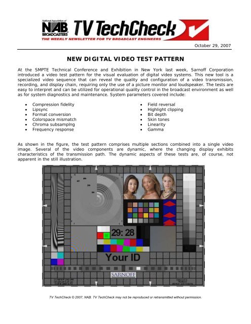
As shown in the figure, the test pattern comprises multiple sections combined into a single video<br />
image. Several <strong>of</strong> the video components are dynamic, where the changing display exhibits<br />
characteristics <strong>of</strong> the transmission path. The dynamic aspects <strong>of</strong> these tests are, <strong>of</strong> course, not<br />
apparent in the still illustration.<br />
Still Image <strong>of</strong> Sarn<strong>of</strong>f Digital Test Pattern<br />
TV TechCheck © 2007, NAB. TV TechCheck may not be reproduced or retransmitted without permission.
The test pattern is available in different versions for HD, SD and digital cinema resolutions and can be<br />
delivered as an A/V file on various digital media.<br />
The following information on the various components <strong>of</strong> the test pattern relates to an interactive<br />
demonstration <strong>of</strong> the system provided to NAB by Norm Hurst <strong>of</strong> Sarn<strong>of</strong>f Corporation, who was<br />
responsible for the development <strong>of</strong> the test pattern.<br />
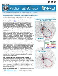
Sweep<br />
Purpose: To measure frequency response and aliasing horizontally and vertically; to measure relative<br />
performance <strong>of</strong> format conversion algorithms.<br />
Description: The left-hand strip is a sweep <strong>of</strong> horizontal frequencies; the right-hand strip is a sweep<br />
<strong>of</strong> vertical frequencies. Each sweep starts at zero frequency at the bottom and increases to the Nyquist<br />
limit (alternating black-white-black-white-…) <strong>of</strong> the format at the top.<br />
The sweeps are sinusoids with a minimum brightness value <strong>of</strong> black and a maximum <strong>of</strong> 75% <strong>of</strong><br />
fullscale. They are angled slightly to accentuate aliasing that may occur, and they slowly change phase<br />
over time, which causes aliasing components to move in reverse.<br />
Compression Fidelity<br />
Purpose: To numerically assess compression fidelity.<br />
Description: Radial sine wave whose frequency increases up to the Nyquist limit at the edges. The<br />
center represents 50 lines per picture height (LPH) and the frequency increases in evenly-spaced<br />
octaves (doublings) up to the Nyquist limit at the edges. A circular gray band indicates each octave and<br />
is labeled in LPH.<br />
The pattern is divided into eight “pie segments”, each with different signal amplitude. The northnortheast<br />
(NNE) segment contains the largest-amplitude signal: the two most-significant bits (MSBs)<br />
are unchanging, so at least 3 bits <strong>of</strong> amplitude resolution are required to see detail. The next segment,<br />
east northeast, is one-half as large as the NNE segment, so the 3 MSBs are unchanging and it requires<br />
at least 4 bits to resolve detail. The “3 4” in the upper right corner indicates that these segments<br />
correspond to bit depths <strong>of</strong> 3 and 4 bits.<br />
Each segment is one-half the amplitude <strong>of</strong> the previous segment and requires one more bit (half the<br />
quantization step size) than the previous segment in order to resolve detail. The pairs <strong>of</strong> numbers in<br />
the corners indicate the bit depth required to resolve detail for the two segments in that quadrant. The<br />
bit-9 and bit-10 segments have no detail in this example because an 8-bit image file was used to<br />
generate this example.<br />
Usage: Shows the effect <strong>of</strong> compression at various quality settings. Look for regions where the detail<br />
vanishes, indicating that the quantization step size is larger than the amplitude <strong>of</strong> the detail in that<br />
region. For each bit-slice, note which octaves retain detail and which do not.<br />
Chroma Zone Plate<br />
Purpose: To indicate chroma resolution, e.g. 4:2:2, 4:2:0.<br />
Description: Radial sine wave whose frequency increases up to the Nyquist limit at the edges. The<br />
lower left corner represents 50 lines per picture height and the frequency increases in evenly-spaced<br />
octaves (doublings) up to the Nyquist limit at the edges. The amplitude is constant. The figure at the<br />
right shows full-resolution, 4:4:4 chroma. The luminance is constant, and remains constant when<br />
transcoded to either ITU-601 or ITU-709 colorspace.<br />
TV TechCheck © 2007, NAB. TV TechCheck may not be reproduced or retransmitted without permission.
Usage: Select from the pulldown menu to see subsampled versions with and without prefiltering.<br />
Skin Tone Reference<br />
Purpose: To provide a quick, subjective check <strong>of</strong> image fidelity.<br />
Description: Pr<strong>of</strong>essionally lit and photographed models representing a range <strong>of</strong> skin tones.<br />
Usage: When it comes to faces, the human visual system is very sensitive—small errors register with<br />
our brains very quickly. Check for accurate skin tone color and gradations. Check for detail such as hair<br />
in dark and light areas. Check that highlights are not blown out, and check that dark areas are not<br />
blocked up.<br />
SMPTE 303M<br />
Purpose: To check proper rendering <strong>of</strong> colors.<br />
Description: A 6 x 4 array <strong>of</strong> color patches, whose color values are as set forth in SMPTE 303M “Color<br />
Reference Pattern” and gamma-encoded as noted in the Format feature.<br />
The first row contains colors found in nature: Dark skin, Light skin, Blue sky, Foliage, Blue flower,<br />
Bluish green. The second row also contains natural colors: Orange, Purplish blue, Moderate red, Purple,<br />
Yellow, green, Orange yellow. The third row contains additive and subtractive primaries: Blue, Green,<br />
Red, Yellow, Magenta, Cyan. The last row consists <strong>of</strong> a six-step neutral gray scale; the neutral values<br />
are Munsell values (the R, G, and B values are not identical).<br />
Usage: Experts familiar with this chart may evaluate it against what they expect to see. Otherwise,<br />
computer s<strong>of</strong>tware may be used to objectively measure the color values <strong>of</strong> each square and compare<br />
those against the values specified in SMPTE-303M.<br />
Lava Lamp<br />
Purpose: To check progressive scan conversion and 4:2:0 interlaced subsampling, and to check for<br />
smooth motion rendition.<br />
Description: Accelerating red diamonds over blue background. The red is 75% red, and the blue is<br />
50%. The speed at the ¼ way point is one line per frame, or one line per field for interlaced formats.<br />
The maximum speed is 2 lines per frame, or 2 lines per field for interlaced formats. The diamonds are<br />
spatially anti-aliased to mimic optically smooth motion.<br />
The slopes on the upper half <strong>of</strong> each diamond are 16 lines from side to center. In the lower half, the<br />
slopes are 8 lines from side to center. Note that the absolute slope, or height-to-width ratio <strong>of</strong> the<br />
diamonds, depends on the vertical resolution <strong>of</strong> the particular format. The number and spacing <strong>of</strong> the<br />
diamonds depends on the frame rate or field rate <strong>of</strong> the particular format.<br />
Usage: Progressive scan conversion: Note the “jaggies” along the edges <strong>of</strong> the diamonds. Note how<br />
the jaggy appearance changes as the speed increases. Better progressive scan converters will maintain<br />
more resolution at higher speeds.<br />
4:2:0 interlaced chroma: Systems like MPEG that vertically subsample the chroma <strong>of</strong> interlaced video<br />
(i.e. 4:2:0 chroma) specify that the chroma from separate fields be kept separate, so that the motion<br />
<strong>of</strong> the luma and the chroma match. An error will be seen as the red portion juddering while the gray<br />
portion moves smoothly. Also, errors in encoding or reconstruction <strong>of</strong> interlaced 4:2:0 chroma may<br />
result in the diamonds having very rough edges.<br />
TV TechCheck © 2007, NAB. TV TechCheck may not be reproduced or retransmitted without permission.
Smooth motion: disturbances in the smoothness <strong>of</strong> the motion are easily seen.<br />
White Pluge<br />
Purpose: To set gain (contrast) <strong>of</strong> a display, especially for LCD displays, to verify that highlights are<br />
not blown out and to check that encoders and decoders do not clip <strong>of</strong>f the signal’s headroom. It is also<br />
used in conjunction with the Colorspace Mismatch Indicator.<br />
Description: Three white strips: 104%, 100%, and 96% <strong>of</strong> full scale.<br />
The sweeps are sinusoids with a minimum brightness value <strong>of</strong> black and a maximum <strong>of</strong> 75% <strong>of</strong><br />
fullscale. They are angled slightly to accentuate aliasing that may occur, and they slowly change phase<br />
over time, which causes aliasing components to move in reverse.<br />
Usage: Before using, adjust display <strong>of</strong>fset (brightness) using the Pluge feature. Reduce display gain<br />
(contrast) until all three strips are visible. (If the boundary between the left and middle strips cannot<br />
be discerned even after reducing the contrast, check upstream processes to see if one <strong>of</strong> them clipped<br />
<strong>of</strong>f the headroom.)<br />
For LCD displays, increase the gain until the boundary between the left and middle strips cannot be<br />
seen. (For CRT displays, increase the gain as desired, but not beyond the point where the first and<br />
second strips merge.)<br />
Colorspace Mismatch Indicator<br />
Purpose: To indicate when clipping occurs as a result <strong>of</strong> decoding YCbCr with the incorrect color<br />
matrix.<br />
Description: Red and green squares with 100% border and a reduced-level inner patch.<br />
Usage: First use the White Pluge feature to force the display to clip at 100%: increase the contrast<br />
until the boundary between the two brightest strips just disappears (LCDs work well for this). Then<br />
verify that the inner patches are visible in the Color Mismatch Indicator. If the red patch blends in with<br />
the red square, this may indicate that YPbPr coded as ITU-601 was decoded using an ITU-709 matrix.<br />
However, if the green patch blends in with the green square, this may indicate that YPbPr coded as<br />
ITU-709 was decoded using an ITU-601 matrix.<br />
Pluge<br />
Purpose: To set black level (brightness) <strong>of</strong> a display; to check that encoders and decoders do not clip<br />
<strong>of</strong>f the signal’s footroom.<br />
Description: Three dark strips: -4%, 0%, +4%, as found in standard color bars conforming to SMPTE<br />
Engineering Guideline EG 1-1990.<br />
Usage: Adjust display <strong>of</strong>fset (brightness) until all three strips are visible, then reduce the brightness<br />
until the boundary between the left and middle strips cannot be seen. If the display cannot be adjusted<br />
to show three separate strips, check upstream equipment for something that may have clipped <strong>of</strong>f the<br />
footroom.<br />
Countdown<br />
Purpose: To provide a countdown for tape leaders; to label each frame and field <strong>of</strong> the test sequence<br />
with a unique number; to detect frame drops and freeze-frames; to measure large lipsync errors.<br />
TV TechCheck © 2007, NAB. TV TechCheck may not be reproduced or retransmitted without permission.
Description: Black on gray numbers indicating seconds and frames remaining to the end <strong>of</strong> the<br />
sequence. The final frame says “00:01”. For interlaced formats, the colon is replaced with a semi-colon<br />
for the first field <strong>of</strong> each frame. The largest value for the frame count depends on the frame rate (e.g.<br />
29 for 30 fps, 23 for 24 fps).<br />
Usage: Use as a leader countdown. Use in frame-by-frame analysis to keep track <strong>of</strong> which frames have<br />
which artifacts. Measure large lipsync errors (greater than one second) using wide-spaced events in the<br />
audio track.<br />
Color Bars<br />
Purpose: To check for correct levels and <strong>of</strong>fset, and to check chroma subsampling phase.<br />
Description: Standard 75% split-field bars with a tilted transition between green and magenta. The tilt<br />
is <strong>of</strong>f-vertical by a slope <strong>of</strong> 8 pixels over the height <strong>of</strong> the bars. It is <strong>of</strong>f-horizontal by 8 lines over the<br />
width <strong>of</strong> the green and magenta bars.<br />
To highlight edge behavior, the chroma in the 4:2:2 rendering <strong>of</strong> the color bars is subsampled without<br />
prefiltering.<br />
Usage: The tilted bars may be used to examine the performance <strong>of</strong> chroma upsampling, and to verify<br />
correct phasing <strong>of</strong> the interpolation with respect to odd and even pixels and lines.<br />
Shallow Ramps<br />
Purpose: To measure visibility <strong>of</strong> contouring due to quantization <strong>of</strong> luma or chroma.<br />
Description: In the first frame there is a shallow, two-dimensional luma ramp rising 12/255 <strong>of</strong><br />
fullscale from the upper left corner to the lower right corner, and a shallow blue ramp, perpendicular to<br />
the luma ramp, rising 24/255 <strong>of</strong> fullscale from the lower left corner to the upper right corner. The two<br />
ramps rotate clockwise together, completing one revolution every two seconds. The figure shows an 8-<br />
bit rendering; the diagonal contour lines are clearly visible.<br />
Usage: Look for rotating contour lines, indicating 8-bit quantization. Conversion from 10 bit to 8 bit<br />
video with careful use <strong>of</strong> dithering may render the contour lines invisible. This feature is particularly<br />
difficult to encode well.<br />
Stairstep<br />
Purpose: To measure gamma, linearity <strong>of</strong> luma, and to set display range.<br />
Description: Eleven luma values evenly distributed over the 0 to 100% range. The left side is linear<br />
“voltage”; the right side is linear light for a particular gamma. The gamma function used to render the<br />
pattern is indicated in the “Format” box. For most formats the gamma function is the one specified by<br />
ITU-709.<br />
The difference between adjacent steps is 10% <strong>of</strong> full range.<br />
The white step at the top and the black step at the bottom have the same value for both linear voltage<br />
and linear light. These steps have additional features, shown in detail below.<br />
The black and white steps each have diagonal “dog ears” that exceed the maximum limits by 2% on<br />
the left and 1% on the right. (All percentages are relative to linear voltage.) They also contain small<br />
TV TechCheck © 2007, NAB. TV TechCheck may not be reproduced or retransmitted without permission.
squares that are within the limits by 2% and 1%. These features blink on and <strong>of</strong>f. The 2% features<br />
blink once per second; the 1% features blink at half that rate.<br />
Usage: The four, small blinking squares should be visible, and the dog ears in black should not be<br />
visible. LCD monitors can be adjusted to make the white dog ears vanish as well.<br />
Adjust monitor brightness until the 1% black dog ears are not visible but the 1% square remains<br />
visible. For LCD-type displays, adjust monitor contrast until the 1% white dog ears vanish but the 1%<br />
square remains visible. Check the brightness adjustment and repeat as necessary.<br />
Lipsync<br />
Purpose: To measure audio/video delay mismatch; to measure chroma motion judder; to detect<br />
interlaced field reversal.<br />
Description: Moving mark over a scale <strong>of</strong> tic marks, and an associated audio track. The mark is 100%<br />
white when moving left-to-right and 100% red when moving right-to-left. When properly synchronized,<br />
the audio beep will be heard when the white moving mark appears at the center. Alternating light gray<br />
and dark gray bars indicate 100 ms each. There is one scale tic mark per frame or field; the number <strong>of</strong><br />
tic marks in each 100 ms bar depends on the frame rate at which the pattern was created. Interlaced<br />
formats have a tic mark for each field.<br />
Usage: Rather than follow the moving mark with your eye, choose one stationary mark and watch for<br />
it to blink while listening for the beep in the audio. If the sound is heard before the flash, choose a<br />
different tic mark to the left and watch again. If the sound is heard after the flash, choose a different<br />
tic mark to the right and watch again. Repeat until you find the tic mark that seems best synchronized<br />
with the sound. Count the number <strong>of</strong> tic marks from that tic to the center to determine the number <strong>of</strong><br />
frames (or fields for interlace) <strong>of</strong> delay <strong>of</strong>fset. With practice, lipsync error can be measured to 1 frame<br />
accuracy.<br />
Interlaced video with chroma processed as non-interlaced will seem to show not one but three red<br />
squares, with the middle one brighter than the other two (see below). This may be more apparent on a<br />
CRT monitor compared to an LCD monitor.<br />
When shown using a display that incorporates a color wheel to achieve RGB, will <strong>of</strong>ten exhibit colorfringing<br />
on the left and right sides <strong>of</strong> the moving white mark.<br />
Audio<br />
Purpose: To measure audio/video delay mismatch; to determine left/right channel swap; to measure<br />
audio levels.<br />
Description: Two-channel audio track with ticks and continuous tone. One tick appears in both<br />
channels every 2.000 seconds (or 2.002 seconds for formats running 1000/1001 slow). This tick occurs<br />
each time the Lipsync indicator flashes at the middle point. Another tick is heard in the right channel<br />
when the Lipsync indicator reaches the right side, and a similar tick is heard when the indicator reaches<br />
the left side.<br />
A continuous tone is heard in both channels. This tone has a level <strong>of</strong> –20 dB FS. The tone mutes for 2<br />
seconds every 10 seconds. Just after the tone mutes, the blinker feature blinks white instead <strong>of</strong> black.<br />
Usage: See the description <strong>of</strong> the Lipsync and Blinker features to use for lipsync measurements. Watch<br />
and listen to the left and right ticks to determine if the left and right channels are reversed: they<br />
should correspond spatially with the movement <strong>of</strong> the Lipsync indicator. Note the level on a VU meter<br />
and adjust gain until it reads –20 dB FS.<br />
TV TechCheck © 2007, NAB. TV TechCheck may not be reproduced or retransmitted without permission.
Lipsync Blinker<br />
Purpose: To measure audio/video delay mismatch using a photodetector and an oscilloscope.<br />
Description: Black or white rectangle that turns to gray when the lip sync audio track beeps. The duty<br />
cycle ratio is 1.5 seconds <strong>of</strong> gray, 0.5 seconds <strong>of</strong> black or white. Black appears except when the<br />
seconds digit <strong>of</strong> the countdown is “2” white appears.<br />
Usage: To measure gross a/v sync, listen for the 1000 Hz tone to stop, then observe the blinker. It<br />
should blink white just after the tone stops. If not, a/v sync may be very far <strong>of</strong>f.<br />
To make accurate measurements <strong>of</strong> small A/V errors: place a photodetector over the blinker and use<br />
an oscilloscope to look at its output. Also look at the audio output with the scope simultaneously. A<br />
storage scope might make this easier. Compare the timing <strong>of</strong> the black-to-gray and white-to-gray<br />
transitions <strong>of</strong> the blinker to the time <strong>of</strong> the beep in the audio track.<br />
This method can be used to measure audio/video timing errors to better than 5 ms accuracy.<br />
Blue Only<br />
Purpose: To set chroma gain (“color”) and phase (“hue” or “tint) <strong>of</strong> NTSC displays.<br />
Description: White, cyan, blue and magenta chips, 75% <strong>of</strong> fullscale. The white is over the blue and<br />
the cyan is over the magenta. This mimics the arrangement <strong>of</strong> the “reversed bars” <strong>of</strong> SMPTE<br />
Engineering Guideline EG 1-1990.<br />
Usage: If the monitor has a “blue only” button, press it. Alternatively you can view the image through<br />
a blue filter, such as the Kodak Wratten Blue 47B Gelatin filter or the Lee Colortran Congo Blue #181.<br />
Adjust the chroma gain and phase until all four chips have the same intensity and appear to blend<br />
together.<br />
For information on Sarn<strong>of</strong>f compliance bitstreams, see: http://www.sarn<strong>of</strong>f.com/bitstreams. Norm<br />
Hurst may be contacted at: nhurst@sarn<strong>of</strong>f.com.<br />
The Shift from Daylight Saving Time Nears<br />
Reminder: All DTV broadcasts should now be announcing in their PSIP that daylight saving time will<br />
end on November 4, 2007.<br />
The ATSC Standard A/65 requires that one month before the shift from daylight saving time that data<br />
announcing the shift be sent. As A/65 is part <strong>of</strong> the FCC regulations, this is required for all DTV<br />
transmissions. Specifically; the following are the proper settings for the following STT fields (as <strong>of</strong> 2<br />
AM, October 4, 2007):<br />
DS_Status = 1<br />
DS_Day_<strong>of</strong>_month=4<br />
DS_Hour=2<br />
TV TechCheck © 2007, NAB. TV TechCheck may not be reproduced or retransmitted without permission.