Installation Instructions - Draw-Tite
Installation Instructions - Draw-Tite
Installation Instructions - Draw-Tite

You also want an ePaper? Increase the reach of your titles
YUMPU automatically turns print PDFs into web optimized ePapers that Google loves.
Form: F205 Rev A 5-6-05<br />
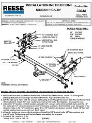
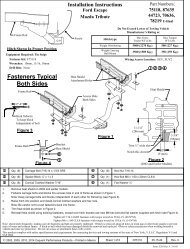
Hitch Shown In Proper Position<br />
Equipment Required:<br />
Fastener Kit: 51007-051<br />
Wrenches: 3/4, 7/8<br />
Drill Bits: 1/2”<br />
Carbon Canister<br />
if equipped<br />
1<br />
2<br />
3<br />
4<br />
5<br />
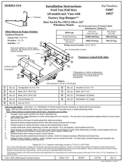
SERIES 51®<br />
Qty. (2)<br />
Qty. (2)<br />
Qty. (4)<br />
Qty. (6)<br />
Qty. (6)<br />
Crossmember<br />
Block .25 X 1.50 X 2.00<br />
Block .25 X 1.50 X 2.00<br />
Conical Washer 1/2<br />
Hex nut 1/2-13<br />
Bumper<br />
Hole to be drilled in vehicle frame,<br />
each side. Be careful not to drill into<br />
Carbon canister<br />
Carriage Bolt 1/2-13 X 1.75<br />
1<br />
2<br />
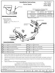
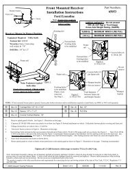
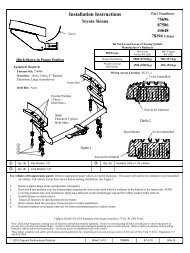
<strong>Installation</strong> <strong>Instructions</strong><br />
Ford Van (Full Size)<br />
All models incl. Vans with<br />
Factory Step Bumper**<br />
Does Not Fit Pre-1992 E-350 or 124”<br />
Wheelbase Models<br />
3<br />
7 3<br />
5 4<br />
*<br />
6<br />
7<br />
8<br />
9<br />
Hitch type<br />
Weight Distributing<br />
Weight Carrying<br />
Ball Mount<br />
6 6<br />
Flat Washer 1/2 (Large)<br />
Part Numbers:<br />
51007<br />
44027<br />
1992 and Later Models – see Figure 1 & 2 Modification of vehicle exhaust may be necessary on vehicle with twin tip exhaust.<br />
**Note: 1992 and later vehicles with factory step bumpers required 12” long ball mount or weight distributing shank.<br />
Note: Wiring harness is located inside vehicle frame. Reposition prior to drilling<br />
1. If present, lower carbon canister from driver’s side frame rail.<br />
2. Lower spare tire. Note: Relocation of under vehicle spare tire is no required. Tire may have to be repositioned slightly forward to avoid contact<br />
with receiver tube.<br />
3. Remove all but a thin layer of undercoating from attaching surfaces.<br />
4. Disconnect factory installed optional driver’s side trailer wiring connector from bumper.<br />
5. Position receiver on vehicle as shown, lining up with existing holes in frame.<br />
6. Loosely install bolts, blocks (depending on model: see Figures 1 & 2), flat washers, conical washers and nuts.<br />
7. Using receiver as a template, drill a 1/2” hole is each frame rail and install 1/2” bolts, block (depending on model), conical washers and nuts.<br />
Note: if existing hole is present, forward slot may be used in place of drilled hole.<br />
8. Reinstall factory trailer wiring connector to clear receiver.<br />
9. Raise spare tire while positioning tire forward on vehicle. Check for clearance between differential and bracket lines.<br />
10. Reattach carbon canister if present – carbon canister must not contact bolt head. If it does loosen canister fasteners and reposition the<br />
canister to ensure clearance with bolt head.<br />
Qty. (4)<br />
Qty. (2)<br />
Qty. (2)<br />
Qty. (2)<br />
Do Not Exceed Lower of Towing Vehicle<br />
Manufacturer’s Rating or<br />
Hex Bolt 1/2-13 X 1.75<br />
Block .25 X 1 X 2<br />
Max Gross<br />
Trailer WT (LB)<br />
10,000 (4540 Kg)<br />
5000 (2270 Kg)<br />
Wiring Access Location: SUV1, SUV2<br />
Flat Washer 1/2 (Small)<br />
Max Tongue<br />
WT (LB)<br />
1000 (454 Kg)<br />
500 (227 Kg)<br />
Tighten all 1/2-13 fasteners with torque wrench to 75 Lb.-Ft. (102 N*M)<br />
Note: check hitch frequently, making sure all fasteners and ball are properly tightened. If hitch is removed, plug all holes in trunk pan or other body panels to<br />
prevent entry of water and exhaust fumes. A hitch or ball which has been damaged should be removed and replaced. Observe safety precautions when working<br />
beneath a vehicle and wear eye protection. Do not cut access or attachment holes with a torch.<br />
This product complies with safety specifications and requirements for connecting devices and towing systems of the state of New York, V.E.S.C. Regulation V-5<br />
and SAE J684.<br />
9<br />
8<br />
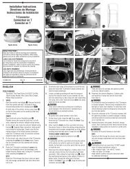
Figure 1.<br />
1992 and later E-350 & E-250 Models<br />
Existing hole in frame<br />
Fasteners typical both sides<br />
* Depending on vehicle configuration,<br />
forward hole may line up with existing<br />
hole in frame – use same fastener<br />
combination<br />
z2001, 2002, 2006 Cequent Towing Products<br />
Sheet 1 of 2<br />
N51007<br />
6-27-06<br />
Rev. A
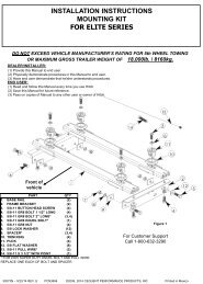
Form: F205 Rev A 5-6-05<br />
Hole to be drilled in vehicle frame-each<br />
side. Be careful not to drill into Carbon<br />
Canister<br />
*<br />
Crossmember<br />
Carbon Canister<br />
if equipped<br />
1<br />
2<br />
5 4 3<br />
6 6<br />
7<br />
8<br />
9<br />
Figure 2.<br />
1992 and Later E-350 Models<br />
Existing hole in frame<br />
Part Numbers:<br />
51007<br />
44027<br />
Fasteners typical both sides<br />
1<br />
2<br />
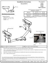
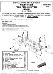
Holes to be drilled in vehicle frame – 3<br />
places each side. Be careful not to drill<br />
into Carbon Canister<br />
Carbon Canister<br />
if equipped<br />
Crossmember<br />
*<br />
*<br />
6<br />
Fasteners typical both sides<br />
6<br />
8<br />
3<br />
5 4 * Depending on vehicle configuration,<br />
forward hole may line up with existing<br />
hole in frame – use same fastener<br />
combination<br />
Figure 3.<br />
Pre-1992 Models Except<br />
E-350 & 124” Wheelbase<br />
Pre-1992 Models – see Figure 3 (Does Not Fit E-350 or 124” Wheelbase)<br />
** Note: 1992 and later vehicle with factory step bumpers require 12” long ball mount or weight distributing shank<br />
Note: On some models, tail pipe and/or tail pipe bracket may have to be relocated and/or modified.<br />
1. If present, lower carbon canister from driver’s side frame rail.<br />
2. Remove all but a thin layer of undercoating from attaching surfaces.<br />
3. Center receiver on vehicle so crossmember frame rivet will fit into step in side bracket.<br />
4. Using hitch as a template, drill three (3) holes per side through frame with 1/2” drill bit.<br />
5. Install fasteners as shown.<br />
6. Reattach carbon canister if present – carbon canister must not contact bolt head. If it does loosen canister fasteners and reposition the<br />
canister to ensure clearance with bolt head.<br />
Tighten all 1/2-13 fasteners with torque wrench to 75 Lb.-Ft. (102 N*M)<br />
Note: check hitch frequently, making sure all fasteners and ball are properly tightened. If hitch is removed, plug all holes in trunk pan or other body panels to<br />
prevent entry of water and exhaust fumes. A hitch or ball which has been damaged should be removed and replaced. Observe safety precautions when working<br />
beneath a vehicle and wear eye protection. Do not cut access or attachment holes with a torch.<br />
This product complies with safety specifications and requirements for connecting devices and towing systems of the state of New York, V.E.S.C. Regulation V-5<br />
and SAE J684.<br />
z 2001, 2002, 2006 Cequent Towing Products<br />
Sheet 2 of 2<br />
N51007<br />
6-27-06<br />
Rev. A