

TM 9-2330-205-14&P
TM 9-2330-205-14&P
TM 9-2330-205-14&P

You also want an ePaper? Increase the reach of your titles
YUMPU automatically turns print PDFs into web optimized ePapers that Google loves.
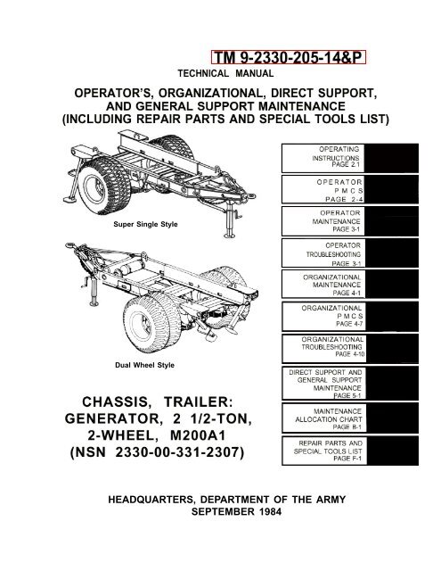
Super Single Style<br />
Dual Wheel Style<br />
HEADQUARTERS, DEPAR<strong>TM</strong>ENT OF THE ARMY<br />
SEPTEMBER 1984
<strong>TM</strong> 9-<strong>2330</strong>-<strong>205</strong>-14&P<br />
WARNING<br />
Drycleaning solvent PD-680 is both toxic and flammable. Avoid prolonged breathing of<br />
vapors and avoid skin contact. Do not use near open flame or excessive heat. Flash<br />
point of solvent is 138°F (59°C). Serious illness, injury, or loss of life could result from<br />
improper use.<br />
WARNING<br />
Improper cleaning methods and use of unauthorized cleaning liquids or solvents can<br />
injure personnel and damage equipment. Refer to <strong>TM</strong> 9-247.<br />
WARNING<br />
Do not operate the trailer with any burned out or missing lights. Not being seen could<br />
result in injury to personnel and damage to equipment.<br />
WARNING<br />
Use care when releasing spring-loaded lower tube of the step jack. The lower tube will<br />
return to retracted position with considerable force and can cause injury.<br />
WARNING<br />
All persons not involved in coupling operation must stand clear of towing vehicle and<br />
trailer to prevent possible injury.<br />
WARNING<br />
Wear protective goggles to prevent eye injury when opening air reservoir draincock.<br />
Move away from airstream to prevent injuries.<br />
WARNING<br />
Particles blown by compressed air are hazardous. Make certain that the airstream is<br />
directed away from user and other personnel in the area. User must wear safety eye<br />
goggles or face shield to prevent injury when using compressed air. Make certain that<br />
air stream is less than 30 psig.<br />
.<br />
WARNING<br />
Before performing any maintenance tasks on brake system, disconnect trailer air lines<br />
from towing vehicle and open draincock to release air pressure from system. Serious<br />
injury may result from failure to do so.<br />
All parts of the service brake assembly will be coated with asbestos dust from the brake<br />
linings. A filter mask should be worn whenever working on any assembly components.<br />
Breathing asbestos dust may cause serious damage to health.<br />
a
<strong>TM</strong> 9-<strong>2330</strong>-<strong>205</strong>-14&P<br />
WARNING<br />
The return spring inside the brake chamber is under heavy spring tension. The two<br />
halves must be clamped together in a vise before removing all the screws and nuts that<br />
hold it together. Failure to do so could result in serious injury.<br />
WARNING<br />
Do not raise landing leg assembly unless the trailer is coupled to a towing vehicle or is<br />
securely supported on jack stands. The trailer may fall, causing injury to personnel.<br />
b
<strong>TM</strong> 9-<strong>2330</strong>-<strong>205</strong>-14&P<br />
C2<br />
HEADQUARTERS<br />
CHANGE<br />
DEPAR<strong>TM</strong>ENT OF THE ARMY<br />
NO. 2 Washington, D.C., 10 April 2006<br />
Operator’s, Organizational,<br />
Direct Support and General Support<br />
Maintenance Manual<br />
(Including Repair Parts and Special Tools List)<br />
CHASSIS, TRAILER: GENERATOR<br />
2-1/2 TON, 2-WHEEL, M200A1<br />
NSN <strong>2330</strong>-00-331-2307<br />
<strong>TM</strong> 9-<strong>2330</strong>-<strong>205</strong>-14&P, 11 September 1984, is changed as follows:<br />
1. Remove old pages and insert new pages as indicated.<br />
2. New or changed material is indicated by a vertical bar in the margin of the new page.<br />
3. A Change 2 beside the page number indicates new or changed material. Added or<br />
revised illustration pages will also include the Change 2 beside the page number.<br />
4. This change implements Army Maintenance Transformation and change the Maintenance<br />
Allocation Chart (MAC) to support Field and Sustainment Maintenance.<br />
Remove Pages Insert Pages Remove Pages Insert Pages<br />
None A/(B Blank) 4-95 thru 4-95 thru<br />
i thru iv i thru iv 4-97/(4-98 Blank) 4-97/(4-98 Blank)<br />
1-0 1-0 5-7 thru None<br />
1-3 thru 1-8 1-3 thru 1-8 5-11/(5-12 Blank)<br />
2-1 thru 2-18 2-1 thru 2-18 B-1 thru B-1 thru B-8<br />
3-3 and 3-4 3-3 and 3-4 B-7/(B-8 Blank)<br />
3-7 and 3-8 3-7 and 3-8 17-1 thru Fig. 21 17-1 thru Fig. 21<br />
4-17 and 4-18 4-17 and 4-18 24-1 and KIT-1 24-1 and KIT-1<br />
4-23 thru 4-28 4-23 thru 4-28 I-1 thru I-12 I-1 thru I-12<br />
4-39 and 4-40 4-39 and 4-40 I-17 thru I-20 I-17 thru I-20<br />
4-45 thru 4-48 4-45 thru 4-48 Index 1 thru 4 Index 1 thru 4<br />
4-57 and 4-58 4-57 and 4-58 Sample 2028 Sample 2028<br />
4-61 and 4-62 4-61 and 4-62 DA Form 2028 DA Form 2028<br />
4-83 and 4-84 4-83 and 4-84 Front Cover Front Cover<br />
4-87 and 4-88 4-87 and 4-88<br />
5. File this change sheet in front of publication for reference.<br />
Approved for public release; distribution is unlimited
By Order of the Secretary of the Army:<br />
Official:<br />
PETER J. SCHOOMAKER<br />
General, United States Army<br />
Chief of Staff<br />
JOYCE E. MORROW<br />
Administrative Assistant to the<br />
Secretary of the Army<br />
0606950<br />
DISTRIBUTION: To be distributed in accordance with the initial distribution requirements<br />
for IDN: 390612, requirements for <strong>TM</strong> 9- <strong>2330</strong>-<strong>205</strong>-14&P.
<strong>TM</strong> 9-<strong>2330</strong>-<strong>205</strong>-14&P<br />
C1<br />
CHANGE<br />
NO. 1<br />
HEADQUARTERS<br />
DEPAR<strong>TM</strong>ENT OF THE ARMY<br />
WASHINGTON, DC, 18March1988<br />
Operator’s, Organizational,<br />
Direct Support, and General Support<br />
Maintenance Manual<br />
(Including Repair Parts and Special Tools List)<br />
CHASSIS, TRAILER: GENERATOR<br />
2-1/2 TON, 2-WHEEL, M200A1<br />
(NSN <strong>2330</strong>-00-331-2307)<br />
Current as of<br />
1 March 1988<br />
<strong>TM</strong> 9-<strong>2330</strong>-<strong>205</strong>-14&P, 11 September 1984, is changed as follows:<br />
1. Remove old pages and insert new pages as indicated. New or<br />
changed material is indicated by a vertical bar in the margin of<br />
the page. Added or revised illustrations are indicated by a<br />
vertical bar adjacent to the illustration identification number.<br />
Remove Pages Insert Pages Remove Pages Insert Pages<br />
i thru iv i thru iv 4-45 and 4-46 4-45 and 4–46<br />
2-11 and 2-12 2-11 and 2-12 4-83 thru 4-86 4-83 thru 4-86<br />
4-3 and 4-4 4-3 and 4-4 F-1 thru F-66 1 thru 66<br />
4-11 and 4-12 4-11 and 4-12 Ind3 and Ind4 Ind3 and Ind4<br />
2. File this change sheet in front of publication for reference.
By Order of the Secretary of the Army:<br />
Official:<br />
CARL E. VUONO<br />
General, United States Army<br />
Chief of Staff<br />
R.L. DILWORTH<br />
Brigadier General, United States Army<br />
The Adjutant General<br />
Distribution:<br />
To be distributed in accordance with DA Form 12-39, Operator UniT; Direct and General Support<br />
Maintenance requirements for Chassis, Trailer, Generator, 2 1/2 Ton, 2-Wheel, M200A1.
LIST OF EFFECTIVE PAGES (for Change 2)<br />
<strong>TM</strong> 9-<strong>2330</strong>-<strong>205</strong>-14&P<br />
INSERT LATEST PAGES. DESTROY SUPERCEEDED DATA.<br />
Oringinal 11 SEP 84<br />
Change 1 18 MAR 88 Change 2 10 APR 06<br />
TOTAL NUMBER OF PAGES FOR FRONT AND REAR MATTER IS 18 AND TOTAL<br />
NUMBER OF PAGES IN CHAPTERS IS 90, CONSISTING OF THE FOLLOWING:<br />
Page No.<br />
*Change No.<br />
Front Cover/Inside Cover -Blank (2 pages) 2<br />
Title/Authenication (2 pages) 2<br />
Transmittal Page/Remove and Insert Page (2 pages) 2<br />
Warnings/a – b (2 pages) 0<br />
i -iv (4 pages) 2<br />
1-0 through 1-8 (10 pages) 2<br />
2-1 through 2-4 (4 pages) 2<br />
2-7 through 2-18 (12 pages) 2<br />
3-3 through 3-4 (2 pages) 2<br />
3-7 through 3-8 (2 pages) 2<br />
4-17 through 4-18 (2 pages) 2<br />
4-23 through 4-28 (6 pages) 2<br />
4-39 through 4-40 (2 pages) 2<br />
4-45 through 4-48 (4 pages) 2<br />
4-57 through 4-58 (2 pages) 2<br />
4-61 through 4-62 (2 pages) 2<br />
4-83 through 4-84 (2 pages) 2<br />
4-87 through 4-88 (2 pages) 2<br />
4-97 through 4-97 (3 pages) 2<br />
4-98 Blank (1 page) 2<br />
B-5 through B-6 (2 pages) 2<br />
Figure 17 through Figure 20 (5 pages) 2<br />
16-1 thorugh 20-1 ( (6 pages) 2<br />
Figure 24 (1 page) 2<br />
24-1/Blank (2 pages) 2<br />
Kit-1/Blank (2 pages) 0<br />
I-1 through I-12 (12 pages) 2<br />
I-17 through I-20 ( 4 pages) 2<br />
Index (4 pages) 2<br />
*Zero in this column indicates an original page.<br />
A/(B Blank) Change 2
'<strong>TM</strong> 9-<strong>2330</strong>-<strong>205</strong>-14&P<br />
TECHNICAL MANUAL<br />
HEADQUARTERS<br />
DEPAR<strong>TM</strong>ENT OF THE ARMY<br />
NO. 9-<strong>2330</strong>-<strong>205</strong>-14&P, C2 WASHINGTON, DC, 11 September 1984<br />
Operator's, Organlzational,<br />
Direct Support, and General Support<br />
Maintenance Manual<br />
(Including Repair Parts and Speclal Tools List)<br />
CHASSIS, TRAILER: GENERATOR<br />
2 ½ TON, 2-WHEEL, M200Al<br />
(NSN <strong>2330</strong>-00-331-2307)<br />
Current as of 3 December 2002<br />
REPORTING ERRORS AND RECOMMENDING IMPROVEMENTS<br />
You can help improve this publication. If you find any mistakes or if you know of a way to improve the procedures, please let<br />
us know. Submit your DA Form 2028 (Recommended Changes to Publications and Blank Forms), through the Internet, on<br />
the Army Electronic Product Support (AEPS) website. The Internet address is http://aeps.ria.army.mil. If you need a<br />
password, scroll down and click on “ACCESS REQUEST FORM”. The DA Form 2028 is located in the ONLINE FORMS<br />
PROCESSING section of the AEPS. Fill out the form and click on SUBMIT. Using this form on the AEPS will enable us to<br />
respond quicker to your comments and better manage the DA Form 2028 program. You may also mail, fax or E-mail your<br />
letter, DA Form 2028 to: AMSTA-LC-LPIT/TECH PUBS, TACOM-RI, 1 Rock Island Arsenal, Rock Island, IL 61299-7630.<br />
The email address is TACOM-TECH-PUBS@ria.army.mil. The fax number is DSN 793-0726 or Commercial (309) 782-0726.<br />
TABLE OF CONTENTS<br />
Page<br />
Illus<br />
Fig.<br />
How to Use This Manual ……………………………………………………………………………….<br />
iv<br />
CHAPTER 1 INTRODUCTION ……………………………………………………………...….… 1-1<br />
Section I. General Information ......................................................................................… 1-1<br />
Section II. Equipment Description and Data ..........................................................……… 1-2<br />
Section III. Principles of Operation ............................................................................……. 1-6<br />
CHAPTER 2 OPERATING INSTRUCTIONS ......................………….......................................... 2-1<br />
Section I. Description and Use of Operator's Controls .........….............................…...... 2-1<br />
Section II. Operator/Crew Preventive Maintenance Checks and Services (PMCS) …… 2-4<br />
Section Ill. Operation Under Usual Conditions ....................................................…......... 2-9<br />
Section IV. Operation Under Unusual Conditions ..........................................……........... 2-16<br />
CHAPTER 3 OPERATOR MAINTENANCE ..................................................…................ 3-1<br />
Section I. Lubrication Instructions ................................................……........................... 3-1<br />
Section II. Operator Troubleshooting Procedures ................................................…...... 3-1<br />
Section III. Operator Maintenance Procedures ……………………………….…………….. 3-3<br />
Approved for public release; distribution is unlimited.<br />
Change 2 i
<strong>TM</strong> 9.<strong>2330</strong>.<strong>205</strong>14&P<br />
TABLE OF CONTENTS -CONTINUED<br />
Page<br />
Illus<br />
Fig.<br />
CHAPTER 4 ORGANIZATIONAL MAINTENANCE ………………………………..…. 4-1<br />
Section I. Lubrication Instructions ………………………………………………….…. 4-2<br />
Section II. Repair Parts, Special Tools; Test, Measurement,<br />
and Diagnostic Equipment (<strong>TM</strong>DE); and Support<br />
Equipment ……………………………………………………………….….. 4-5<br />
Section III. Service Upon Receipt ……………………………………………………..… 4-5<br />
Section IV.<br />
Organizational Preventive Maintenance Checks and Services<br />
(PMCS) … 4-7<br />
Section V. Organizational Troubleshooting Procedures ………………………… 4-10<br />
Section VI. General Maintenance instructions …………………………………………. 4-14<br />
Section VII. Electrical System …………………………………………………………….. 4-16<br />
Section VIII. Axle ................................…………………................................................. 4-31<br />
Section IX. Brake System …………………………………………………………………. 4-36<br />
Section X. Wheel, Tire, Hub, and Drum ………………………………………………… 4-76<br />
Section Xi. Frame and Towing Attachment …………………………………………….. 4-82<br />
Section Xii. Spring …………………………………………………………………………. 4-88<br />
Section XIII. Body Accessory ………………………………………………………………. 4-93<br />
Section XIV. Preparation for Storage and Shipment …………………………………….. 4-96<br />
CHAPTER 5 DIRECT SUPPORT AND GENERAL SUPPORT MAINTENANCE …… 5-1<br />
Section I. Repair Parts, Special Tools; Test, Measurement,<br />
and Diagnostic Equipment (<strong>TM</strong>DE); and Support<br />
Equipment ……………………………………………………………………. 5-1<br />
Section II. Maintenance Procedures …………………………………………………… 5-1<br />
APPENDIX A REFERENCES ……………………………………………………………… A-1<br />
APPENDIX B MAINTENANCE. ALLOCATlON CHART ………………………………… B-1<br />
APPENDIX C<br />
COMPONENTS OF END ITEM AND BASIC ISSUE<br />
ITEMS LIST ………………………………………………………………….. C-1<br />
APPENDIX D ADDITIONAL AUTHORIZATION LIST ……………………………………. D-1<br />
APPENDIX E EXPENDABLE SUPPLIES AND MATERIALS LIST ……………………. E-1<br />
APPENDIX F REPAIR PARTS AND SPECIAL TOOLS LIST ………………………….. 1<br />
ii<br />
Section I. Introduction …………………………………………………………………. 1<br />
Section II. Repair Parts List ……………………………………………………….……<br />
Group 06 ELECTRICAL SYSTEM<br />
0609 Blackout Stoplight Assembly (Early Models) …………………….. 1<br />
0609 Service, Stop, and Tail and Blackout Taillight<br />
(Early Models) ……………………………………………………….. 2
<strong>TM</strong> 9-<strong>2330</strong>-<strong>205</strong>-14&P<br />
TABLE OF CONTENTS - CONTINUED<br />
Page<br />
Illus<br />
Fig.<br />
0609 Rear Composite Marker Light Assembly<br />
(Late Models) ……….......................................................... 3<br />
0613 Intervehicular Cable ……………………………………............……. 4<br />
0613 Chassis Wiring Harness for Blackout Stoplight<br />
Assembly …………………………………………………….......… 5<br />
0613 Chassis Wiring Harness Service, Stop, Tail,<br />
and Blackout Taillight ……………………………………........... 6<br />
Group 11<br />
Group 12<br />
Group 13<br />
Group 15<br />
Group 16<br />
Group 22<br />
Section III.<br />
Section IV.<br />
REAR AXLE<br />
1100 Axle Assembly ……………………………………...........…………. 7<br />
BRAKES<br />
1201 Handbrake Lever Mechanism …………………………...........…… 8<br />
1202 Brake Assembly ……………………………………………..........… 9<br />
1204 Master Cylinder Hydraulic Brake Assembly ………........…........ 10<br />
1204 Hydraulic Wheel Cylinder ………………………………..........….. 11<br />
1204 Hydraulic Brake System …………………………………..........…. 12<br />
1208 Air Brake System …………………………………………..........…. 13<br />
1208 Air Chamber Assembly ……………………………..........….…….. 14<br />
1208 Air Filter …………………………………………………...........……. 15<br />
1208 Emergency Relay Valve ………………………..........………….…. 16<br />
WHEELS<br />
1311 Hub and Drum Assembly …………………………………............. 17<br />
1311 Hub and Drum Assembly (for use with Super<br />
Single Style) ……………………………………………….....…. 17A<br />
1313 Tire and Tube ………………………………………...............…… 18<br />
1313 Tire (for use with Super Single Style) ……................….............. 18A<br />
FRAME AND TOWING ATTACHMENTS; LANDING GEAR AND LEVELING JACK<br />
1503 Lunette, Safety Chains, and Mounting Support ……............….. 19<br />
1507 Landing Leg Assembly ……………………………………........…. 20<br />
1507 Step Jack Assembly ……………………………………........……. 21<br />
SPRINGS AND SHOCK ABSORBERS<br />
1601 Spring Assembly ………………………………………….......…… 22<br />
BODY AND CHASSIS ACCESSORY ITEMS<br />
2202 Reflectors ………………………………………………….......…… 23<br />
2210 Identification Plates ……………………………………….......….. 24<br />
Special Tools (Not Applicable)…………………………………….......…<br />
National Stock Number and Part Number Index ……….......…………<br />
APPENDIX G TORQUE LIMITS ………………………………………....………………. G1<br />
INDEX ………………………………………………………………................…. Index-1<br />
Change 2 iii
<strong>TM</strong> 9-<strong>2330</strong>-<strong>205</strong>-14&P<br />
HOW TO USE THIS MANUAL<br />
This manual is designed to help you operate and maintain the M200A1 Generator<br />
Trailer. The front cover table of contents is provided for quick reference to important<br />
information. There is also an index located in the final pages for use in locating<br />
specific items of information.<br />
Measurements in this manual are given in both US standard and metric units. A metric<br />
to US standard conversion chart can be found on the inside back cover.<br />
Read all preliminary information found at the beginning of each task. It has important<br />
Information and safety instructions you must follow before beginning the task.<br />
Warning pages are located in the front of this manual. You should read the warnings<br />
Before operating or doing maintenance on the equipment.<br />
A subject index appears at the beginning of each chapter listing sections that are<br />
included in that chapter. A more specific subject index is located at the beginning of<br />
each section to help you find the exact paragraph you’re looking for.<br />
iv
<strong>TM</strong> 9-<strong>2330</strong>-<strong>205</strong>-14&P<br />
Super Single Style<br />
Dual Wheel Style<br />
1-0 Change 2
<strong>TM</strong> 9-<strong>2330</strong>-<strong>205</strong>-14&P<br />
CHAPTER 1<br />
INTRODUCTION<br />
OVERVIEW<br />
The purpose of this chapter is to give you information on the generator trailer chassis size, shape,<br />
major equipment, and how it works.<br />
Section I. General Information . . . . . . . . . . . . . . . . . . . . . . . . . . . . . . . . . . . . . . . . . . . . . . . . . . . . . . . . . . . . . . . . . . . . . . . . . . . . . . . . . . . . . . . 1-1<br />
Section Il. Equipment Description and Data . . . . . . . . . . . . . . . . . . . . . . . . . . . ........ . . . . . . . . . . . . . . . . . . . . . . . . . . . . . 1-2<br />
Section Ill. Principles of Operation . . . . . . . . . . . . . . . . . . . . . . . . . . . . . . . . . . . . . . . . . . . . . . . . . . . . . . . . . . . . . . . . . . . . . . . . . . . . . . . . . . 1-6<br />
Page<br />
Section L GENERAL INFORMATION<br />
Page<br />
Page<br />
Destruction of Army Materiel<br />
Preparation for Storage and<br />
to Prevent Enemy Use . . . . . . . . . . . . . . . . . . . . . . . . . . . . . 1-1 Shipment . . . . . . . . . . . . . . . . . . . . . . . . . . . . . . . . . . . . . . . . . . . . . . . . 1-2<br />
Maintenance Forms and<br />
Reporting Equipment Improvement<br />
Records . . . . . . . . . . . . . . . . . . . . . . . . . . . . . . . . . . . . . . . . . . . . . . . . . . . . . 1-1 Recommendations (EIRs) . . . . . . . . . . . . . . . . . . . . . 1-2<br />
Nomenclature Cross-Reference Scope . . . . . . . . . . . . . . . . . . . . . . . . . . . . . . . . . . . . . . . . . . . . . . . . . . . . . . . . . . 1-1<br />
List . . . . . . . . . . . . . . . . . . . . . . . . . . . . . . . . . . . . . . . . . . . . . . . . . . . . . . . . . . . . . 1-2<br />
SCOPE<br />
Type of Manual: Operator’s, Organizational, Direct Support, and General Support Maintenance<br />
Manual (Including Repair Parts and Special Tools Lists).<br />
Model Number and Equipment Name: M200A1 Chassis, Trailer: Generator, 2 1/2-Ton, 2-Wheel.<br />
Purpose of Equipment: The trailer is used to transport electric generators. It can be used on<br />
improved and unimproved roads.<br />
MAINTENANCE FORMS AND RECORDS<br />
Department of the Army forms and procedures used for equipment maintenance will be those prescribed<br />
by <strong>TM</strong> 38-750, The Army Maintenance Management System (TAMMS).<br />
DESTRUCTION OF ARMY MATERIEL TO PREVENT ENEMY USE<br />
Refer to <strong>TM</strong> 750-244-6, Procedures for Destruction of Tank-Automotive Equipment to Prevent Enemy<br />
Use (US Army Tank-Automotive Command).<br />
1-1
<strong>TM</strong> 9-<strong>2330</strong>-<strong>205</strong>-14&P<br />
PREPARATION FOR STORAGE AND SHIPMENT<br />
See chapter 4, section XIV for instructions for the preparation for storage or shipment.<br />
REPORTING EQUIPMENT IMPROVEMENT RECOMMENDATIONS (EIRs)<br />
If your generator trailer needs improvement, let us know. Send us an EIR. You, the user, are the only<br />
one who can tell us what you don’t like about your equipment. Let us know why you don’t like the<br />
design. Put it on an SF 368 (Quality Deficiency Report). Mail it to Commander, US Army Tank-<br />
Automotive Command, Attn: DRSTA-MP, Warren Ml 48090. We will send you a reply.<br />
NOMENCLATURE CROSS-REFERENCE LIST<br />
Common Name<br />
TOW hook<br />
Tow ring<br />
Official Nomenclature<br />
Pintle<br />
Coupler, drawbar, Iunette, ring<br />
Section IL EQUIPMENT DESCRIPTION AND DATA<br />
Page<br />
Page<br />
Equipment Characteristics,<br />
Location and Description of<br />
Capabilities, and Features . . . . . . . . . . . . . . . . . . . . . 1-2 Major Components . . . . . . . . . . . . . . . . . . . . . . . . . . . . . . . . 1-3<br />
Equipment Data . . . . . . . . . . . . . . . . . . . . . . . . . . . . . . . . . . . . . . . . . . . 1-5<br />
EQUIPMENT CHARACTERISTICS, CAPABILITIES, AND FEATURES<br />
PURPOSE OF M200A1 GENERATOR TRAILER CHASSIS<br />
An open-frame, single-axle, four-wheeled trailer chassis designed to transport an electric<br />
generator.<br />
CAPABILITIES AND FEATURES<br />
Load Capacity:<br />
Highway, 7000 lb (3158 kg)<br />
Cross country, 5000 lb (2270 kg)<br />
May be towed by a 2 1/2-ton, 6 x 6, M35 cargo truck or similar vehicle.<br />
Speed is restricted to 55 mph (88.5 km/h) on improved roads and 30 mph (48.3 km/h) on<br />
unimproved roads or cross country.<br />
It can ford hard-bottom water crossings to any depth that can be negotiated by the towing vehicle.<br />
1-2
<strong>TM</strong> 9-<strong>2330</strong>-<strong>205</strong>-14&P<br />
LOCATION AND DESCRIPTION OF MAJOR COMPONENTS<br />
LANDING LEG<br />
The landing leg supports the front of the trailer when uncoupled and can be used to raise or lower the front of the<br />
trailer.<br />
The crank handle drives the gearbox, which extends or retracts the landing leg.<br />
The landing leg and back brace are locked in the down position or in the folded back and stowed position by a<br />
Lockpin.<br />
DATA PLATES<br />
There are two data plates on the right front frame. They provide identification, registration, dimension, and<br />
weight information.<br />
TA223284<br />
Change 2 1-3
<strong>TM</strong> 9-<strong>2330</strong>-<strong>205</strong>-14&P<br />
LOCATION AND DESCRIPTION OF MAJOR COMPONENTS - CONTINUED<br />
ELECTRICAL SYSTEM<br />
The electrical system is the 24-volt military vehicle system with an intervehicular cable to connect the trailer to<br />
the towing vehicle.<br />
The taillights and composite lights provide stopping and turning signals.<br />
STEP JACKS<br />
The step jacks are located at the left- and right-rear corners of the chassis and serve as stabilizers when the<br />
chassis is uncoupled from the towing vehicle.<br />
Each step jack has a step to provide access to upper parts of mounted equipment.<br />
Each step jack has an adjustable spring-loaded lower tube with a hinged pad attached to its base. The lower<br />
tube telescopes within the step tube and can be locked in any of seven positions by the latch.<br />
Super Single Style Shown<br />
1-4 Change 2<br />
TA223285
<strong>TM</strong> 9-<strong>2330</strong>-<strong>205</strong>-14&P<br />
LOCATION AND DESCRIPTION OF MAJOR COMPONENTS - CONTINUED<br />
BRAKE SYSTEM<br />
The brake system is an air-actuated, hydraulically operated system.<br />
EQUIPMENT DATA<br />
Axle<br />
Type<br />
Diameter<br />
Spindle dia.<br />
Brakes<br />
Type<br />
Operating pressure<br />
Size, diameter<br />
Size, width<br />
Type mechanism<br />
Electrical system, 24-volt<br />
Lamps, blackout<br />
Lamps, service<br />
Frame<br />
Material<br />
Height<br />
Handbrakes<br />
Actuation<br />
Location<br />
Tubular<br />
4 1/2.(114 mm)<br />
2 13/16 in. (52 mm)<br />
Air over hydraulic<br />
60 psi (414 kPa) minimum<br />
16.0705 in. (408 mm)<br />
3 in. (76 mm)<br />
2-shoe, self-centering,<br />
expanding double-cylinder actuation<br />
3 cp<br />
32 cp<br />
Welded pressed steel<br />
38 in. (965 mm)<br />
Mechanical hand levers<br />
Forward side rails<br />
TA223286<br />
Change 2 1-5
<strong>TM</strong> 9-<strong>2330</strong>-<strong>205</strong>-14&P<br />
EQUIPMENT DATA - CONTINUED<br />
THIS PAGE CONTAINS DATA FOR THE SUPER SINGLE STYLE ONLY. THE DATA FOR THE OLDER STYLE<br />
M200 SERIES TRAILER IS ON PAGE 1-6.<br />
Landing leg<br />
Length extended<br />
Length retracted<br />
31 in. (787 mm)<br />
23 in. (584 mm)<br />
Springs<br />
Material<br />
Steel alloy<br />
Number of leaves 14<br />
Type<br />
Semielliptical<br />
Tires (Super Single Models)<br />
Number (Including Spare) 3<br />
Size 10R22.5<br />
Inflation (cross country)<br />
70 psi (483 kPa)<br />
(highway)<br />
70 psi (483 kPa)<br />
(mud, snow, and sand)<br />
70 psi (483 kPa)<br />
Type (Manufacturer)<br />
Goodyear Tire and Rubber Co.<br />
Weights and dimensions<br />
Length (to center of Iunette)<br />
Width (overall)<br />
Height (top of tires)<br />
Weight (empty)<br />
Payload (cross country)<br />
(highway)<br />
Angle of departure<br />
162 1/5 in. (411 cm)<br />
89 in. (236 cm)<br />
37.75 in. (100 cm)<br />
2015 lb (1093 kg)<br />
5000 lb (2268 kg)<br />
7000 lb (3175 kg)<br />
30-degree slope<br />
Wheels<br />
Number of studs<br />
6 each Rim<br />
Manufacturer<br />
Pribbs Steel & Mfg., Inc.<br />
Rim Size<br />
7.5x22.5in. (19x57cm)<br />
Number (Including Spare) 3<br />
1-6 Change 2
<strong>TM</strong> 9-<strong>2330</strong>-<strong>205</strong>-14&P<br />
EQUIPMENT DATA - CONTINUED<br />
Landing leg<br />
Length extended<br />
Length retracted<br />
Springs<br />
Material<br />
Number of leaves<br />
Type<br />
Tires<br />
Number<br />
Number of plies<br />
Size<br />
Inflation (cross country)<br />
(highway)<br />
(mud, snow, and sand)<br />
Type<br />
Weights and dimensions<br />
Length (to center of Iunette)<br />
Width (overall)<br />
Height (top of tires)<br />
Weight (empty)<br />
Payload (cross country)<br />
(highway)<br />
Angle of departure<br />
Wheels<br />
Diameter of stud circle<br />
Number of studs<br />
Rim size<br />
Tire retention<br />
Type<br />
Bearing type<br />
Number<br />
31 in. (787 mm)<br />
23 in. (584 mm)<br />
Steel alloy<br />
14<br />
Semielliptical<br />
4<br />
8<br />
9.00 x 20<br />
20 psi (138 kPa)<br />
35 psi (241 kPa)<br />
15 psi (103 kPa)<br />
Military pneumatic<br />
161 7/8 in. (411 cm)<br />
93 in. (236 cm)<br />
40 in. (102 cm)<br />
2410 lb (1093 kg)<br />
5000 lb (2268 kg)<br />
7000 lb (3175 kg)<br />
30-degree slope<br />
8.743 in. (222 mm)<br />
6 each<br />
20 x 7.5<br />
Split ring<br />
Offset disk<br />
Tapered roller<br />
4<br />
Section Ill. PRINCIPLES OF OPERATION<br />
Page<br />
Page<br />
Brake System . . . . . . . . . . . . . . . . . . . . . . . . . . . . . . . . . . . . . . . . . . . . 1-7 Electrical System . . . . . . . . . . . . . . . . . . . . . . . . . . . . . . . . . . . . . . . . . . 1-8<br />
1-6.1/(1-6.2 Blank)
<strong>TM</strong> 9-<strong>2330</strong>-<strong>205</strong>-14&P<br />
Gladhands - The gladhands are the coupling point for the trailer to towing vehicle. They are marked, one for<br />
emergency and the other for service, to ensure correct hookup.<br />
Air Filters - The air filters clean air from towing vehicle of moisture and foreign matter,<br />
Air Lines - The air lines extend from the air filters to supply service and emergency air to the relay valve, air<br />
reservoir, and brake air chamber.<br />
Relay Valve - Controls the braking system of the trailer. Based on the air pressure signals received from the<br />
towing vehicle, it will apply or release the service brakes or it will initiate an emergency brake application.<br />
Air Reservoir - The air reservoir stores the system air pressure (60 psi (413.7 kPa) minimum) that operates the<br />
brake system. Pressure to the reservoir is initially supplied and then maintained through the emergency supply<br />
line from the towing vehicle through the relay valve.<br />
Brake Air Chamber - The brake air chamber converts air pressure to mechanical motion. This movement, through<br />
the hydraulic master cylinder, applies the brakes. When air pressure in the brake air chamber is released, spring<br />
action releases the brakes.<br />
Hydraulic Master Cylinder - The hydraulic master cylinder converts the mechanical motion of the brake air<br />
chamber to hydraulic pressure.<br />
Wheel Cylinders - The wheel cylinders convert system hydraulic pressure to mechanical motion and force the<br />
brake lining against the brakedrum.<br />
Brakeshoes - The two brakeshoes on each wheel assembly are spread apart by the mechanical movement of<br />
the wheel cylinders. The brakeshoes cause friction to slow or stop the trailer.<br />
TA223287<br />
1-7 Change 2
<strong>TM</strong> 9-<strong>2330</strong>-<strong>205</strong>-14&P<br />
The light assemblies receive power to operate from the towing vehicle through the intervehicular cable<br />
and the main chassis harness.<br />
TA224447<br />
1-8
OVERVIEW<br />
CHAPTER 2<br />
OPERATING INSTRUCTIONS<br />
<strong>TM</strong> 9-<strong>2330</strong>-<strong>205</strong>-14&P<br />
This chapter shows and describes the trailer controls and contains operator/crew level preventive maintenance<br />
procedures. There are instructions for coupling trailer to towing vehicle, driving, stopping, and backing, operation<br />
in both usual and unusual conditions, and other information to help you understand and better operate the trailer.<br />
Page<br />
Section I. Description and Use of Operator’s Controls ................................................................ 2-1<br />
Section II. Operator/Crew Preventive Maintenance<br />
Checks and Services (PMCS).......................................................................... 2-4<br />
Section III. Operation Under Usual Conditions ........................................................................... 2-9<br />
Section IV. Operation Under Unusual Conditions ....................................................................... 2-16<br />
Section I. DESCRIPTION AND USE OF OPERATOR’S CONTROLS<br />
Page<br />
Page<br />
Air Reservoir ...................................... 2-1 Step Jack ............................................ 2-3<br />
Handbrakes ....................................... 2-2<br />
Trailer-to-Towing Vehicle<br />
Landing Leg ....................................... 2-4 Connectors .......................................... 2-3<br />
Lunette and Safety Chain .................... 2-2<br />
AIR RESERVOIR<br />
KEY CONTROL OR INDICATOR FUNCTION<br />
1 Draincock Used to drain accumulation of moisture<br />
and to release air pressure in the<br />
event of locked brakes.<br />
Change 2 2-1
<strong>TM</strong> 9-<strong>2330</strong>-<strong>205</strong>-14&P<br />
Super Single Style Shown<br />
KEY CONTROL OR INDICATOR FUNCTION<br />
1 Handbrake lever The handbrake lever assemblies are used to<br />
apply or release the handbrakes.<br />
2 Adjustment knobs Use to adjust cable tension.<br />
LUNETTE AND SAFETY CHAIN<br />
KEY CONTROL OR INDICATOR FUNCTION<br />
1 Lunette Used to couple the trailer to the towing<br />
vehicle.<br />
2 Safety chain Hooked to eyebolts on towing vehicle to<br />
prevent trailer from fully breaking away.<br />
2-2 Change 2<br />
TA223289
<strong>TM</strong> 9-<strong>2330</strong>-<strong>205</strong>-14&P<br />
TRAILER-TO-TOWING VEHICLE CONNECTORS<br />
KEY CONTROL OR INDICATOR FUNCTION<br />
1 Intervehicular cable Provides the connection between the towing<br />
vehicle connector and the trailer<br />
electrical system.<br />
2 Service and emergency Provide the connections between the towing<br />
vehicle’s gladhands air supply and the<br />
trailer.<br />
STEP JACK<br />
Super Single Style Shown<br />
KEY CONTROL OR INDICATOR FUNCTION<br />
1 Step jack Acts as a stabilizer at the rear of the<br />
trailer and provides a step to gain access to<br />
upper parts of equipment mounted on trailer.<br />
2 Latch Locks Lower tube in any of seven positions.<br />
TA223290<br />
Change 2 2-3
<strong>TM</strong> 9-<strong>2330</strong>-<strong>205</strong>-14&P<br />
LANDING LEG<br />
KEY CONTROL OR INDICATOR FUNCTION<br />
1 Landing leg Provides support for forward end of chassis when<br />
not coupled to a towing vehicle.<br />
2 Lockpin Attaches back brace to landing leg to secure<br />
landing leg in the down position,<br />
3 Back brace Provides fore and aft stability for the<br />
landing leg.<br />
4 Lockpin Locks the landing leg in the folded position.<br />
5 Crank handle Operates the gearbox. Turning crank clockwise<br />
retracts shoe assembly, lowering trailer.<br />
Turning crank counterclockwise extends shoe<br />
assembly, raising trailer.<br />
Section II. OPERATOR/CREW PREVENTIVE MAINTENANCE<br />
CHECKS AND SERVICES (PMCS)<br />
Page<br />
Page<br />
General .................................................. 2-5 PMCS Column Description ..................... 2-6<br />
Leakage Definitions ................................ 2-6 Special Instructions ................................ 2-5<br />
Operator/Crew Preventive<br />
Maintenance Checks and<br />
Services ............................................... 2-6<br />
2-4 Change 2<br />
TA223291
<strong>TM</strong> 9-<strong>2330</strong>-<strong>205</strong>-14&P<br />
GENERAL<br />
This section contains instructions for performing PMCS on the trailer. The procedure lists checks,<br />
services, and criteria to ensure that the trailer is prepared for operation. Perform the checks and<br />
services at the specified intervals, keeping in mind the following guidelines:<br />
Do your before (B) PMCS just before operating the vehicle. Pay attention to CAUTIONS and<br />
WARNINGS.<br />
Do your during (D) PMCS while operating the vehicle. During means to monitor the vehicle and its<br />
related parts while being operated.<br />
Do your after (A) PMCS right after operating the vehicle. Pay attention to CAUTIONS and WARNINGS.<br />
SPECIAL INSTRUCTIONS<br />
If something doesn’t work, troubleshoot it with the instructions in this manual and notify your<br />
supervisor.<br />
Always do your preventive maintenance in the same order so it gets to be a habit. Once you’ve had<br />
some practice, you’ll spot anything wrong in a hurry.<br />
If anything looks wrong and you can’t fix it, write it on a DA Form 2404. if you find something seriously<br />
wrong, report it to organizational maintenance immediately.<br />
When you do your preventive maintenance, take along the tools you need to make all the checks. You<br />
always need a rag or two.<br />
WARNING<br />
Drycleaning solvent PD-680 is both toxic and flammable. Avoid prolonged breathing of<br />
vapors and avoid skin contact. Do not use near open flame or excessive heat. Flash point<br />
of solvent is 138°F (59°C). Serious illness, injury, or loss of life could result from<br />
improper use.<br />
Keep it Clean. Dirt, grease, oil, and debris only get in the way and may cover up a serious problem.<br />
Clean as you work and as needed. Use drycleaning solvent PD-680 on all metal surfaces. Use soap<br />
and water to clean rubber or plastic material.<br />
Bolts, Nuts, and Screws. Check that they are not loose, missing, bent, or broken. Look for chipped<br />
paint, bare metal, or rust around boltheads. Report loose nuts and bolts to organizational<br />
maintenance.<br />
Welds. Look for loose or chipped paint, rust, or gaps where parts are welded together. Report bad<br />
welds to organizational maintenance.<br />
Electric Wires and Connectors. Look for cracked or broken insulation, bare wires, and loose or<br />
broken connectors. Report loose connections and faulty wiring to organizational maintenance.<br />
Hoses and Air Lines. Look for wear, damage, or leaks. Make sure clamps and fittings are tight. If a<br />
leak comes from a loose fitting or connector, or if something is broken or worn out, notify<br />
organizational maintenance.<br />
2-5
<strong>TM</strong> 9-<strong>2330</strong>-<strong>205</strong>-14&P<br />
LEAKAGE DEFINITIONS<br />
It is necessary for you to know how fluid leaks affect the status of the trailer. The following are<br />
definitions of the types/classes of leakage needed to determine the status of the trailer. Become<br />
familiar with them. When in doubt, notify your supervisor.<br />
Class I – Seepage of fluid (indicated by wetness or discoloration) not great enough to form drops.<br />
Class II – Leakage of fluid great enough to form drops, but not enough to cause drops to fall.<br />
Class Ill – Leakage of fluid great enough to form drops that fall.<br />
CAUTION<br />
When operating with class I or II leaks, check fluid levels more often than that required in<br />
the PMCS. Hydraulic brake systems with leaks will stop working if fluid levels are not<br />
maintained.<br />
Equipment operation is allowable with minor leaks (class I or II). Consideration must be<br />
given to the fluid capacity of the trailer hydraulic system. Notify your supervisor when in<br />
doubt.<br />
Class Ill leaks must be reported to your supervisor or organizational maintenance.<br />
PMCS COLUMN DESCRIPTION<br />
Item No. – The order that PMCS should be performed, and also used as a source of item numbers for<br />
the <strong>TM</strong> number column on DA Form 2404, Equipment Inspection and Maintenance Worksheet, when<br />
recording results of PMCS.<br />
Interval<br />
– Tells when each check is to be performed.<br />
Hem To Be Inspected – Lists the check to be performed.<br />
Equipment Is Not Ready/Available If – Has an entry only when the trailer should not be operated or<br />
accepted with that problem.<br />
OPERATOR/CREW PREVENTIVE MAINTENANCE CHECKS AND SERVICES<br />
B-BEFORE D-DURING A-AFTER<br />
ITEM<br />
NO.<br />
INTERVAL<br />
B D A<br />
ITEM TO BE INSPECTED<br />
PROCEDURE: CHECK FOR AND HAVE<br />
REPAIRED, FILLED, OR ADJUSTED<br />
AS NEEDED<br />
EQUIPMENT IS NOT<br />
READY/AVAILABLE IF:<br />
1.<br />
TIRES (1)<br />
●<br />
a. Check for excessive wear and<br />
damage.<br />
Tires are unserviceable.<br />
●<br />
b. Remove any glass, nails, or stones.<br />
2-6
<strong>TM</strong> 9-<strong>2330</strong>-<strong>205</strong>-14&P<br />
OPERATOR/CREW PREVENTIVE MAINTENANCE CHECKS AND SERVICES - CONTINUED<br />
B-BEFORE D-DURING A-AFTER<br />
INTERVAL<br />
ITEM TO BE INSPECTED<br />
PROCEDURE: CHECK FOR AND HAVE<br />
ITEM REPAIRED, FILLED, OR ADJUSTED EQUIPMENT IS NOT<br />
NO. B D A AS NEEDED READY/AVAILABLE IF:<br />
* c. Gage and inflate to 70 psi<br />
(483 kPa).<br />
2. * WHEELS<br />
Check for missing or loose wheel<br />
capnuts (2).<br />
Capnuts loose or<br />
missing.<br />
3. * SERVICE BRAKE SYSTEM<br />
Check for evidence of fluid leaks<br />
at master cylinder (3), brake<br />
lines (4), and backing plates (5).<br />
Class III leakage<br />
is evident.<br />
Both Styles Shown<br />
4. * LIGHTS AND REFLECTORS<br />
Check for missing or damaged<br />
components.<br />
Lights or reflectors<br />
damaged or missing.<br />
Change 2 2-7
<strong>TM</strong> 9-<strong>2330</strong>-<strong>205</strong>-14&P<br />
OPERATOR/CREW PREVENTIVE MAINTENANCE CHECKS AND SERVICES - CONTINUED<br />
B-BEFORE D-DURING A-AFTER<br />
INTERVAL ITEM TO BE INSPECTED<br />
PROCEDURE: CHECK FOR AND HAVE<br />
ITEM REPAIRED, FILLED, OR ADJUSTED EQUIPMENT IS NOT<br />
NO. B D A AS NEEDED READY/AVAILABLE IF:<br />
5. * LUNETTE, AIRHOSES, INTERVEHICULAR<br />
CABLE, AND SAFETY CHAINS<br />
Check condition of Lunette (1),<br />
air-hoses (2), cable (3),<br />
and chains (4).<br />
Parts are<br />
unserviceable.<br />
6. * LANDING LEG AND STEP JACK<br />
Check condition of landing leg (5)<br />
Indication a leg<br />
and step jacks (6). might collapse.<br />
Super Single Style Shown<br />
7. * HANDBRAKES<br />
8. * BRAKES<br />
Check operation and adjust<br />
(page 3-4).<br />
Check for proper operation.<br />
Brakes will<br />
not hold.<br />
9. * SUSPENSION AND LOAD<br />
a. Listen for unusual noise.<br />
b. Check for defective suspension<br />
or shifting load.<br />
2-8 Change 2<br />
TA223293
OPERATOR/CREW Preventive Maintenance CHECKS AND SERVlCES - CONTINUED<br />
B-BEFORE D-DURING A-AFTER<br />
<strong>TM</strong> 9-<strong>2330</strong>-<strong>205</strong>-14&P<br />
ITEM TO BE INSPECTED<br />
INTERVAL PROCEDURE: CHECK FOR AND HAVE<br />
ITEM REPAIRED, FILLED, OR ADJUSTED EQUIPMENT IS NOT<br />
NO. B D A AS NEEDED READY/AVAILABLE IF:<br />
10. * AIR RESERVOIR<br />
Open draincock (1) to drain<br />
reservoir and close when<br />
finished.<br />
11. * FRAME AND SUSPENSION<br />
Check frame and suspension<br />
for damage.<br />
Section Ill. OPERATION UNDER USUAL CONDITIONS<br />
Page<br />
Page<br />
After Use............................................. 2-14 Preparation for Use..................................... 2-9<br />
Operation ............................................ 2-13<br />
PREPARATION FOR USE<br />
Perform the operator/crew preventive maintenance checks and services in the Before (B) column before continuing<br />
with the following procedures.<br />
WARNING<br />
All persons not involved in coupling operation must stand clear of<br />
towing vehicle and trailer to prevent possible injury.<br />
1. Review and perform towing vehicle operating procedures to prepare towing vehicle for coupling.<br />
TA223294<br />
Change 2 2-9
<strong>TM</strong> 9-<strong>2330</strong>-<strong>205</strong>-14&P<br />
PREPARATION FOR USE - CONTINUED<br />
2. Align towing vehicle with trailer.<br />
NOTE<br />
Use an assistant to direct you while backing up.<br />
3. Slowly back towing vehicle until Lunette (1) and pintle (2) engage.<br />
4. Install pintle Lockpin (3).<br />
5. Attach safety chains (4) from trailer to towing vehicle by crossing chain under Lunette to opposite side<br />
eyebolt.<br />
6. Connect trailer intervehicular cable (5) to towing vehicle.<br />
7. Connect trailer service (7) and emergency (6) airhose gladhands to towing vehicle gladhands (8 and 9).<br />
8. Check airhose gladhands (6 and 7) and intervehicular cable (5) connector for security.<br />
9. Turn on towing vehicle air supply to pressurize the brake system air reservoir (10).<br />
10. Turn on service Lights in towing vehicle and check that all taillights (11) are working.<br />
2-10 Change 2<br />
TA223295
<strong>TM</strong> 9-<strong>2330</strong>-<strong>205</strong>-14&P<br />
PREPARATION FOR USE - CONTINUED<br />
11.<br />
12.<br />
Have an assistant turn on turn signals and apply service brakes. Check that taillights/composite<br />
lights (11) flash and brake lights light.<br />
Check blackout portions of taillights/composite lights (11) for proper operation. Also check<br />
operation of blackout stoplight (12) if equipped.<br />
WARNING<br />
Use care when releasing spring-loaded lower tube of step jack. The lower tube will<br />
return to retracted position with considerable force and can cause injury.<br />
13.<br />
14.<br />
15.<br />
16.<br />
17.<br />
Release lower tube latches (13).<br />
Remove retaining pins (14).<br />
Remove step jack Iockpins (15).<br />
Swing step jacks inward and install Iockpins (15).<br />
Install retaining pins (14).<br />
TA223296<br />
2-11
<strong>TM</strong> 9-<strong>2330</strong>-<strong>205</strong>-14&P<br />
PREPARATION FOR USE - CONTINUED<br />
WARNING<br />
Do not raise landing leg assembly unless trailer is connected to a<br />
towing vehicle or is securely supported on jack stands.<br />
The trailer may fall, causing injury to personnel.<br />
18. Rotate crank handle (1) until landing leg (2) is fully retracted.<br />
19. Position crank handle (1) at its lowest point of rotation.<br />
20. Remove retaining pin (3) and lockpin (4) securing back brace (5) to landing leg (2).<br />
21. Allow back brace (5) to swing down.<br />
22. Rotate landing leg (2) back and up to its stowed position.<br />
23. Install lockpin (6) and retaining pin (7) through landing leg (2) and frame bracket.<br />
24. Swing back brace (5) forward and up and install lockpin (4) and retaining pin (3).<br />
25. Release handbrake levers (8).<br />
26. Have an assistant apply and release towing vehicle service brakes.<br />
27. Check that trailer relay valve (9) vents with each application and release of towing vehicle service brakes.<br />
Venting of air should be heard.<br />
2-12 Change 2
<strong>TM</strong> 9-<strong>2330</strong>-<strong>205</strong>-14&P<br />
PREPARATION FOR USE - CONTINUED<br />
OPERATION<br />
DRIVING<br />
When driving the towing vehicle and trailer, the overall length of the unit must be kept in mind when passing other<br />
vehicles and when turning. Backing is also affected because the unit is hinged in the middle.<br />
TURNING<br />
When turning corners, allow for the fact that the trailer wheels turn inside the turning radius of the towing vehicle.<br />
Make right turns by driving the towing vehicle about halfway into intersection, and then cutting sharply to the<br />
right. This will keep trailer wheels off the curb. Keep the vehicle close enough to the edge of the road to prevent<br />
vehicles following from passing on the right.<br />
STOPPING<br />
During normal operation, stepping on the brake pedal will apply both towing vehicle and trailer brakes at the<br />
same time. Apply brakes gradually and smoothly.<br />
PARKING<br />
When parking for extended periods, both the towing vehicle and trailer parking brakes should be set. You cannot<br />
use the trailer service brakes for long-term parking. The air pressure is gradually and automatically vented if they<br />
are left applied. The service brakes will release as the air is vented.<br />
TA223298<br />
Change 2 2-13
<strong>TM</strong> 9-<strong>2330</strong>-<strong>205</strong>-14&P<br />
OPERATION - CONTINUED<br />
BACKING<br />
Use an assistant to guide you while backing. Adjust rear-view mirrors before backing. When the towing vehicle<br />
and trailer are in a straight line, the rear of the trailer will move opposite to the direction the front towing vehicle<br />
wheels are turned. When the towing vehicle wheels are turned to the right, the rear of the trailer will move to the<br />
left as you back up. When the towing vehicle wheels are turned to the left, the rear of the trailer will move to the<br />
right.<br />
Super Single Style Shown<br />
AFTER USE<br />
1. Remove retaining pin (1) and lockpin (2), allowing back brace (3) to swing down and back.<br />
2. Remove retaining pin (4) and lockpin (5) from landing leg (6) and frame bracket (7) allowing landing<br />
leg to swing down and forward.<br />
3. Swing back brace (3) forward and secure it to landing leg (6) with lockpin (2) and retaining pin (1).<br />
4. Rotate crank handle (8) counterclockwise to extend landing leg (6) and remove trailer weight from<br />
pintle.<br />
2-14 Change 2<br />
TA223299
<strong>TM</strong> 9-<strong>2330</strong>-<strong>205</strong>-14&P<br />
AFTER USE - CONTINUED<br />
5. Swing step jack (9) inward and remove retaining pins (10) and lockpins (11).<br />
6. Allow step jack (9) to swing down and out.<br />
7. Aline lockpin holes in step jacks (9) and frame (12).<br />
8. Install Iockpins (11) and retaining pins (10).<br />
9. Extend lower tubes (13) by stepping on hinged pads (14).<br />
TA2<strong>2330</strong>0<br />
Change 2 2-15
<strong>TM</strong> 9-<strong>2330</strong>-<strong>205</strong>-14&P<br />
AFTER USE - CONTINUED<br />
10. Unhook safety chains (1) from towing vehicle and hook to trailer tiedown loop (2).<br />
11. Close air supply valves on towing vehicle.<br />
12. Uncouple service (4) and emergency (3) air gladhands from towing vehicle and secure to dummy couplings<br />
(5) on trailer.<br />
13. Unplug intervehicular cable connector (6) and stow loop (7).<br />
14. Set trailer handbrakes (8) and release air pressure from air reservoir (9).<br />
15. Remove safety pin (10) from pintle (11).<br />
16. Have an assistant drive towing vehicle to uncouple lunette (12) from pintle (11).<br />
Section IV. OPERATION UNDER UNUSUAL CONDITIONS<br />
Page<br />
Page<br />
Fording ............................................... 2-18 Operation in Saltwater Areas ................. 2-17<br />
Operation in Extreme Cold .................... 2-17 Operation in Sandy or Dusty<br />
Operation in Extreme Heat .................... 2-17 Areas .................................................. 2-17<br />
Operation in Mud ................................. 2-17 Operation in Snow ................................ 2-17<br />
2-16 Change 2<br />
TA2<strong>2330</strong>1
<strong>TM</strong> 9-<strong>2330</strong>-<strong>205</strong>-14&P<br />
OPERATION IN EXTREME COLD<br />
1. Refer to the lubrication chart (page 4-3) for proper lubricants to use in extreme cold.<br />
2. Extreme cold can cause insulation material on electrical wire to crack and cause short circuits, and<br />
other construction materials to become hard, brittle, and easily damaged or broken.<br />
3. Tires may freeze to ground or have flat spots if underinflated.<br />
4. Brakeshoes may freeze to brakedrum and will need to be heated to prevent damage to mating surfaces.<br />
5. Refer to FM 9-207 and FM 21-305 for special instructions on driving hazards in extreme cold.<br />
6. When parking short term, park in a sheltered area out of the wind.<br />
7. For parking long term, place footing of planks or brush under trailer wheels, landing gear, and step jack.<br />
8. Remove all built-up ice, snow, and mud as soon as possible after use.<br />
9. Shield the trailer with canvas covers, if available. Keep cover ends off the ground to keep them from<br />
freezing to the ground.<br />
OPERATION IN EXTREME HEAT<br />
1. Refer to the lubrication chart for proper lubricants to use in extreme heat.<br />
2. Do not park the trailer in sunlight for long periods of time. Heat and sunlight shorten tire life. Shelter or<br />
cover the trailer with canvas if available.<br />
OPERATION IN SANDY OR DUSTY AREAS<br />
Clean, inspect, and lubricate more often in dusty or sandy areas.<br />
OPERATION IN SNOW<br />
See FM 21-305 for special instructions on operating in snow.<br />
OPERATION IN SALTWATER AREAS<br />
Saltwater will cause rapid rust and corrosion to develop. Clean, inspect, and lubricate more often than<br />
scheduled.<br />
OPERATION IN MUD<br />
Thoroughly clean and lubricate all parts contaminated by mud as soon as possible after operating in mud.<br />
Pack wheel bearings if necessary.<br />
Change 2 2-17
<strong>TM</strong> 9-<strong>2330</strong>-<strong>205</strong>-14&P<br />
FORDING<br />
1. Check bottom surface of stream or river. If bottom surface is too soft, do not ford.<br />
2. After fording, apply the brakes a few times to help dry out the brake lining. Be sure brakes are<br />
operating properly before driving at normal speeds.<br />
3. Lubricate all unpainted surfaces with lubricating oil.<br />
4. Lubricate the trailer in accordance with the lubrication chart on page 4-3.<br />
5. Refer to <strong>TM</strong> 9-238 for deepwater fording information.<br />
2-18
<strong>TM</strong> 9-<strong>2330</strong>-<strong>205</strong>-14&P<br />
CHAPTER 3<br />
OPERATOR MAINTENANCE<br />
OVERVIEW<br />
This chapter contains the lubrication and troubleshooting maintenance instructions and procedures<br />
authorized at operator level.<br />
Section I. Lubrication Instructions . . . . . . . . . . . . . . . . . . . . . . . . . . . . . . . . . . . . . . . . . . . . . . . . . . . . . . . . . . . . . . . . . . . . . . . . . . . . . . . . 3-1<br />
Section Il. Operator Troubleshooting Procedures . . . . . . . . . . . . . . . . . . . . . . . . . . . . . . . . . . . . . . . . . . . . . . . . . . . . . . . . 3-1<br />
Section Ill. Operator Maintenance Procedures . . . . . . . . . . . . . . . . . . . . . . . . . . . . . . . . . . . . . . . . . . . . . . . . . . . . . . . . . . . . . . 3-3<br />
Page<br />
Section I. LUBRICATION INSTRUCTIONS<br />
Lubrication under usual and unusual conditions and the trailer lubrication chart are contained in<br />
organizational maintenance, chapter 4.<br />
Section II. OPERATOR TROUBLESHOOTING PROCEDURES<br />
Page<br />
Page<br />
Explanation of Columns . . . . . . . . . . . . . . . . . . . . . . . . . . . . . . 3-1 Operator Troubleshooting . . . . . . . . . . . . . . . . . . . . . . . . 3-2<br />
General . . . . . . ..... . . . . . . . . . . . . . . . . . . . . . . . . . . . . . . . . . . . . . . . . . . . . . . 3-1 Symptom Index . . . . . . . . . . . . . . . . . . . . . . . . . . . . . . . . . . . . . . . . . . 3-2<br />
GENERAL<br />
This section lists the common malfunctions that you may find during operation of the trailer and its<br />
components. Perform the tests, inspections, and corrective actions in the order listed.<br />
This manual cannot list all malfunctions that may occur, nor all tests or inspections and corrective<br />
actions. If a malfunction is not listed, or is not corrected by the corrective actions listed, notify your<br />
supervisor.<br />
EXPLANATION OF COLUMNS<br />
Malfunction. Visual or operational indication that something is wrong with the trailer.<br />
Test/Inspection. Procedure to isolate problem to a component or system.<br />
Corrective Action. Procedure to correct problem.<br />
3-1
<strong>TM</strong> 9-<strong>2330</strong>-<strong>205</strong>-14&P<br />
SYMPTOM INDEX<br />
This symptom index is provided as a guide to the troubleshooting procedure that will help you solve the<br />
problem you’re having.<br />
ELECTRICAL SYSTEM<br />
All lamps fail to light . . . . . . . . . . . . . . . . . . . . . . . . . . . . . . . . . . . . . . . . . . . . . . . . . . . . . . . . . . . . . . . . . . . . . . . . . . . . . . . . . . . . . . . . . . . . . . . . . . . . . . . . . . . . . . . . . . . . . . . . . . . 3-2<br />
One or more (but not all) lamps fail to light . . . . . . . . . . . . . . . . . . . . . . . . . . . . . . . . . . . . . . . . . . . . . . . . . . . . . . . . . . . . . . . . . . . . . . . . . . . . . . . . . . . . . . 3-2<br />
Page<br />
BRAKES<br />
No brakes . . . . . . . . . . . . . . . . . . . . . . . . . . . . . . . . . . . . . . . . . . . . . . . . . . . . . . . . . . . . . . . . . . . . . . . . . . . . . . . . . . . . . . . . . . . . . . . . . . . . . . . . . . . . . . . . . . . . . . . . . . . . . . . . . ......... ... 3-3<br />
OPERATOR TROUBLESHOOTING<br />
MALFUNCTION<br />
TEST OR INSPECTION<br />
CORRECTIVE ACTION<br />
1. ALL LAMPS FAIL TO LIGHT.<br />
ELECTRICAL SYSTEM<br />
Step 1.<br />
Check that intervehicular cable is properly connected.<br />
Reconnect.<br />
Step 2.<br />
Check towing vehicle circuit breaker/fuse.<br />
Refer to towing vehicle technical manual for maintenance<br />
instructions.<br />
If lamps still do not light, notify organizational maintenance.<br />
2. ONE OR MORE (BUT NOT ALL) LAMPS FAIL TO LIGHT.<br />
Check for loose connector at affected light.<br />
Reconnect.<br />
If lamp still fails to light, notify organizational maintenance.<br />
3-2
<strong>TM</strong> 9-<strong>2330</strong>-<strong>205</strong>-14&P<br />
OPERATOR TROUBLESHOOTING - CONTINUED<br />
MALFUNCTION<br />
TEST OR INSPECTION<br />
CORRECTIVE ACTION<br />
3. NO BRAKES.<br />
BRAKES<br />
Step 1.<br />
Check for open draincock on air reservoir.<br />
Close draincock.<br />
Step 2.<br />
Check for closed air valves on towing vehicle.<br />
Open air valves.<br />
Step 3.<br />
Check air line gladhands for proper connection (emergency-to-emergency<br />
and service-to-service).<br />
Reconnect.<br />
If you still have no brakes, notify organizational maintenance.<br />
step 4.<br />
Check for hydraulic leaks.<br />
Notify organizational maintenance.<br />
Section Ill. OPERATOR MAINTENANCE PROCEDURES<br />
Page<br />
Page<br />
Handbrake . . . . . . . . . . . . . . . . . . . . . . . . . . . . . . . . . . . . . . . . . . . . . . . . . . . . 3-4 Wheel and Tire . . . . . . . . . . . . . . . . . . . . . . . . . . . . . . . . . . . . . . . . . . . 3-5<br />
Personnel are listed only if the task requires more than one technician. If Personnel<br />
Required is not listed, one technician can do the task.<br />
3-3
<strong>TM</strong> 9-<strong>2330</strong>-<strong>205</strong>-14&P<br />
HANDBRAKE<br />
This task covers:<br />
Adjustment<br />
INITIAL SETUP<br />
Tools<br />
Jack, hydraulic<br />
ACTION<br />
LOCATION ITEM REMARKS<br />
NOTE<br />
Procedure is for one handbrake. Repeat procedure for opposite side.<br />
1. Axle (1) Wheels (2) Using hydraulic jack (3), raise.<br />
2. Chassis Handbrake Release.<br />
lever (4)<br />
3. Handbrake Adjusting Adjust by turning clockwise to tighten or<br />
lever (4) knob (5) counterclockwise to loosen.<br />
Wheel and tire should lock when<br />
hand-brake lever travels no more<br />
than two-thirds.<br />
4. Chassis Handbrake Release.<br />
lever (4)<br />
Wheel and tire should turn freely.<br />
5. Axle Wheels (2) Using hydraulic jack, lower.<br />
Remove jack.<br />
TASK ENDS HERE<br />
Super Single Style Shown<br />
TA2<strong>2330</strong>2<br />
3-4 Change 2
<strong>TM</strong> 9-<strong>2330</strong>-<strong>205</strong>-14&P<br />
WHEEL AND TIRE<br />
This task covers:<br />
a. Removal (page 3-5)<br />
b. Installation (page 3-6)<br />
INITIAL SETUP<br />
Tools<br />
Handle, 3/4-inch square drive<br />
Jack, hydraulic<br />
Tools – Continued<br />
Socket, wheel, 1 1/2-by 7/8- by<br />
3/4-inch square drive<br />
ACTION<br />
LOCATION ITEM REMARKS<br />
REMOVAL<br />
NOTE<br />
Outer capnuts are marked R on right wheel and L on left wheel. Nuts must be turned in<br />
opposite direction to normal forward rotation of wheel to be loosened or removed.<br />
1. Wheels and tires<br />
(1 and 2)<br />
2. Axle (5)<br />
3. Six inner<br />
capnuts (4)<br />
4.<br />
Six outer (3) and<br />
six inner (4) capnuts<br />
Wheels and tires<br />
(1 and 2)<br />
Six outer<br />
capnuts (3)<br />
Outer wheel and<br />
tire (1)<br />
Using wheel socket, loosen nuts.<br />
Do not remove nuts.<br />
Using hydraulic jack (6), raise.<br />
Using wheel socket, remove.<br />
Remove.<br />
TA2<strong>2330</strong>3<br />
3-5
<strong>TM</strong> 9-<strong>2330</strong>-<strong>205</strong>-14&P<br />
WHEEL AND TIRE - CONTINUED<br />
ACTION<br />
LOCATION ITEM REMARKS<br />
REMOVAL – CONTINUED<br />
5. Inner wheel (1)<br />
6. Hub (3)<br />
Six inner<br />
capnuts (2)<br />
Inner wheel (1)<br />
Using wheel socket, remove.<br />
Remove.<br />
INSTALLATION<br />
7. Inner wheel (1)<br />
Hub (2) Position wheel on hub studs (3).<br />
8.<br />
Six inner<br />
capnuts (4)<br />
Using wheel socket, install.<br />
Tighten using illustrated tightening<br />
sequence.<br />
3-6<br />
TA2<strong>2330</strong>4
<strong>TM</strong> 9-<strong>2330</strong>-<strong>205</strong>-14&P<br />
WHEEL AND TIRE - CONTINUED<br />
ACTION<br />
LOCATION ITEM REMARKS<br />
9. Six inner Outer wheel (5) Place in position.<br />
capnuts (4)<br />
Position inner and outer<br />
valve stems as far apart as<br />
possible.<br />
10. Six outer Using wheel socket, install.<br />
capnuts (6)<br />
Tighten using illustrated<br />
tightening sequence.<br />
11. Axle (7) Wheels and tires Using hydraulic jack (8), lower.<br />
(1 and 5) Remove jack.<br />
12. Outer wheel (5) Six inner (4) and Using wheel socket and illustrated<br />
six outer capnuts(6) tightening sequence, retighten.<br />
NOTE<br />
Have organizational maintenance torque capnuts using torque wrench to<br />
450 to 500 ft lb (610 to 678 N•m).<br />
TASK ENDS HERE<br />
TA2<strong>2330</strong>5<br />
Change 2 3-7
<strong>TM</strong> 9-<strong>2330</strong>-<strong>205</strong>-14&P<br />
WHEEL AND TIRE<br />
(Super Single Style)<br />
This task covers:<br />
a. Removal (page 3-5)<br />
b. Installation (page 3-6)<br />
INITIAL SETUP<br />
Tools<br />
Tools – Continued<br />
Handle, 3/4-inch square drive Socket, wheel, 1 1/2-by 7/8- by<br />
Jack, hydraulic 3/4-inch square drive<br />
ACTION<br />
LOCATION ITEM REMARKS<br />
REMOVAL<br />
1. Wheel and tire Six capnuts Using wheel socket, loosen nuts.<br />
(1) (4) Do not remove nuts.<br />
2. Axle Wheel and Using hydraulic jack, raise.<br />
tire (1)<br />
3. Hub studs (3) 12 capnuts (4) Using wheel socket, remove capnuts.<br />
4. Hub (2) Wheel and Remove.<br />
tire (1)<br />
INSTALLATION<br />
5. Hub (2) Wheel and tire Position wheel on hub studs (3).<br />
(1)<br />
6. Hub studs (3) Six capnuts Using wheel socket, install. (4)<br />
(4) Tighten using illustrated<br />
tightening sequence.<br />
7. Axle Wheel and tire Using hydraulic jack, lower.<br />
(1) Remove jack.<br />
NOTE<br />
Have organizational maintenance torque capnuts using<br />
torque wrench to 450 to 500 ft lb (610 to 678 N•m).<br />
3-8 Change 2
<strong>TM</strong> 9-<strong>2330</strong>-<strong>205</strong>-14&P<br />
CHAPTER 4<br />
ORGANIZATIONAL<br />
MAINTENANCE<br />
OVERVIEW<br />
This chapter contains all the maintenance authorized to be performed by organizational maintenance.<br />
Page<br />
Section I.<br />
Section Il.<br />
Section III.<br />
Section IV.<br />
Section V.<br />
Section VI.<br />
Section VIl.<br />
Section Vlll.<br />
Section IX.<br />
Section X.<br />
Section XI.<br />
Section XII.<br />
Section XIII.<br />
Section XIV.<br />
Lubrication Instructions . . . . . . . . . . . . . . . . . . . . . . . . . . . . . . . . . . . . . . . . . . . . . . . . . . . . . . . . . . . . . . . . . . . . . . . . . . . . . .<br />
Repair Parts, Special Tools; Test, Measurement,<br />
and Diagnostic Equipment (<strong>TM</strong>DE); and Support<br />
Equipment . . . . . . . . . . . . . . . . . . . . . . . . . . . . . . . . . . . . . . . . . . . . . . . . . . . . . . . . . . . . . . . . . . . . . . . . . . . . . . . . . . . . . . . .<br />
Service Upon Receipt . . . . . . . . . . . . . . . . . . . . . . . . . . . . . . . . . . . . . . . . . . . . . . . . . . . . . . . . . . . . . . . . . . . . . . . . . . . . . . . . . . .<br />
Organizational Preventive Maintenance Checks and<br />
Services . . . . . . . . . . . . . . . . . . . . . . . . . . . . . . . . . . . . . . . . . . . . . . . . . . . . . . . . . . . . . . . . . . . . . . . . . . . . . . . . . . . . . . . . . . . . . . . . . . . .<br />
Organizational Troubleshooting Procedures . . . . . . . . . . . . . . . . . . . . . . . . . . . . . . . . . . . . . . . . . . . .<br />
General Maintenance Instructions . . . . . . . . . . . . . . . . . . . . . . . . . . . . . . . . . . . . . . . . . . . . . . . . . . . . . . . . . . . . .<br />
Electrical System. . . . . . . . . . . . . . . . . . . . . . . . . . . . . . . . . . . . . . . . . . . . . . . . . . . . . . . . . . . . . . . . . . . . . . . . . . . . . . . . . . . . . . . . . .<br />
Axle . . . . . . . . . . . . . . . . . . . . . . . . . . . . . . . . . . . . . . . . . . . . . . . . . . . . . . . . . . . . . . . . . . . . . . . . . . . . . . . . . . . . . . . . . . . . . . . . . . . . . . . . . . . . . . . .<br />
Brake System . . . . . . . . . . . . . . . . . . . . . . . . . . . . . . . . . . . . . . . . . . . . . . . . . . . . . . . . . . . . . . . . . . . . . . . . . . . . . . . . . . . . . . . . . . . . . . . .<br />
Wheel, Tire, Hub, and Drum . . . . . . . . . . . . . . . . . . . . . . . . . . . . . . . . . . . . . . . . . . . . . . . . . . . . . . . . . . . . . . . . . . . . . . . .<br />
Frame and Towing Attachment . . . . . . . . . . . . . . . . . . . . . . . . . . . . . . . . . . . . . . . . . . . . . . . . . . . . . . . . . . . . . . . . . .<br />
Spring . . . . . . . . . . . . . . . . . . . . . . . . . . . . . . . . . . . . . . . . . . . . . . . . . . . . . . . . . . . . . . . . . . . . . . . . . . . . . . . . . . . . . . . . . . . . . . . . . . . . . . . . . . . .<br />
Body Accessory . . . . . . . . . . . . . . . . . . . . . . . . . . . . . . . . . . . . . . . . . . . . . . . . . . . . . . . . . . . . . . . . . . . . . . . . . . . . . . . . . . . . . . . . . . . .<br />
Preparation for Storage and Shipment . . . . . . . . . . . . . . . . . . . . . . . . . . . . . . . . . . . . . . . . . . . . . . . . . . . . . .<br />
4-2<br />
4-5<br />
4-5<br />
4-7<br />
4-10<br />
4-14<br />
4-16<br />
4-31<br />
4-36<br />
4-76<br />
4-82<br />
4-88<br />
4-93<br />
4-96<br />
4-1
<strong>TM</strong> 9-<strong>2330</strong>-<strong>205</strong>-14&P<br />
Section I. LUBRICATION INSTRUCTIONS<br />
Page<br />
Page<br />
Lubrication Chart . . . . . . . . . . . . . . . . . . . . . . . . . . . . . . . . . . . . . . . . . 4-3 Lubrication Instructions . . . . . . . . . . . . . . . . . . . . . . . . . . . 4-2<br />
LUBRICATION INSTRUCTIONS<br />
GENERAL<br />
Keep all lubricants in closed containers and store in a clean, dry place away from external heat. Keep<br />
container covers clean and allow no dust, dirt, or other foreign material to mix with the lubricants.<br />
Keep all lubrication equipment clean and ready for use.<br />
CLEANING<br />
Keep all external parts not requiring lubrication free of lubricants. Before lubricating the equipment,<br />
wipe all lubrication points free of dirt and grease. Clean all lubrication points after servicing to prevent<br />
accumulation of foreign matter.<br />
LUBRICATION INTERVAL<br />
Service the lubrication points at the proper intervals as specified in the lubrication chart. The intervals<br />
specified are based on operation under normal conditions. Modification of the recommended intervals<br />
may be required under unusual operating conditions.<br />
LUBRICATION CHART<br />
Refer to the lubrication chart on the following page for lubrication under normal conditions. Refer to<br />
FM 9-207 for instructions on lubrication in weather below 0°F (-18°C). Refer to <strong>TM</strong> 9-238 for instructions<br />
on lubrication before and after fording. Clean and inspect all lubrication points after<br />
operating in mud, dust, sand, or other unusual conditions. Lubricate the trailer in accordance with<br />
the lubrication chart.<br />
4-2
<strong>TM</strong> 9-<strong>2330</strong>-<strong>205</strong>-14&P<br />
LUBRICATION CHART<br />
CHASSIS, TRAILER: GENERATOR<br />
2 1/2 TON, 2-WHEEL, M200A1<br />
(<strong>2330</strong>-00-331-2307)<br />
Hard-time intervals and related man-hour times are based on<br />
normal operation, The man-hour time specified is the time<br />
you need to do all services prescribed for a particular interval.<br />
Change the interval if your lubricants are contaminated or if<br />
you are operating equipment under adverse conditions,<br />
including longer-than-usual operating hours. The interval<br />
may be extended during periods of low activity. If extended,<br />
adequate preservation precautions must be taken.<br />
Dotted leader lines indicate lubrication is required on both<br />
sides of the equipment.<br />
WARNING<br />
Drycleaning solvent PD-680 is both toxic and flammable.<br />
Avoid prolonged breathing of vapors and avoid skin contact,<br />
Do not use near open flame or excessive hoot. Flash point of<br />
solvent is 138° F (59° C). Serious illness, injury, or loss of<br />
life could result from improper use.<br />
Clean all fittings and area around lubricating points with<br />
drycleaning solvent PD-680 or equivalent before lubricating.<br />
LUBRICANT ● INTERVAL<br />
INTERVAL ● LUBRICANT<br />
Step jack<br />
(See Note 3.)<br />
GAA<br />
GAA<br />
Spring shackles<br />
Spring shackle<br />
bolts<br />
GAA<br />
(two fittings)<br />
GAA<br />
Emergency<br />
brake cable<br />
Wheel bearing<br />
(See Note 4.)<br />
GAA<br />
Landing<br />
leg gearbox<br />
(See Note 5.)<br />
GAA<br />
BFS<br />
Hydraulic<br />
brake master<br />
cylinder<br />
TOTAL MAN-HOURS*<br />
INTERVAL<br />
MAN-HOURS<br />
A 1.5<br />
S 0.7<br />
* The time specified is the time required to perform all services at the particular interval.<br />
TA2<strong>2330</strong>6<br />
4-3
C1, <strong>TM</strong> 9-<strong>2330</strong>-<strong>205</strong>-14&P<br />
LUBRICANTS<br />
-KEY–<br />
EXPECTED TEMPERATURES<br />
ABOVE +15° F +40° F TO -15° F<br />
(ABOVE -9°C) (+4° C TO -26° C)<br />
+40° F TO -65° F<br />
(+4° F TO -54° C)<br />
INTERVALS<br />
OE/HDO Lubricating oil,<br />
internal<br />
combustion<br />
engine, tactical<br />
service<br />
OE/HDO-30<br />
OE/HDO-10<br />
A – Annually<br />
S – Semiannually<br />
OEA<br />
Lubricating oil,<br />
internal<br />
combustion,<br />
arctic<br />
Oilcan points<br />
(See Note 2.)<br />
OEA<br />
(See Note 1.)<br />
BFS<br />
GAA<br />
Brake fluid<br />
silicone,<br />
automotive<br />
Master cylinder<br />
Grease,<br />
automotive<br />
and artillery<br />
All Temperatures<br />
All Temperatures<br />
NOTES:<br />
1. For operation of equipment in protracted cold temperatures<br />
below -15° F (-26° C), remove lubricants prescribed in<br />
the key for temperatures above -15° F (-26° C). Relubricate<br />
with lubricants specified in the key for temperatures below<br />
-15° F (-26° C). If OEA lubricant is required to meet the<br />
temperature changes prescribed in the key, OEA lubricant is<br />
to be used in place of OE/HDO-10 lubricant for all temperature<br />
ranges where OE/HDO-10 lubricant is specified in the<br />
key.<br />
2. Oilcan Points. Every 6 months, lubricate linkage, pins,<br />
clevises, and all exposed adjusting threads with OE/HDO.<br />
3. Step Jack: Every 6 months, extend inner leg fully and<br />
coat lightly with GAA.<br />
4. Wheel Bearings: Every 12 months, remove, clean, and<br />
repack with GAA. Refer to <strong>TM</strong> 9-214, Inspection, Care,<br />
and Maintenance of Antifriction Bearings.<br />
5. Landing Leg Gearbox Lubricate at time of disassembly.<br />
6, Lubricants: The following is a list of lubricants with<br />
military symbols and applicable specification numbers:<br />
OE/HDO – MIL-L-2104C<br />
GAA – MIL-G-10924C<br />
OEA – MIL-L-46167<br />
BFS – MIL-B-46176<br />
TA2<strong>2330</strong>7<br />
4-4
<strong>TM</strong> 9-<strong>2330</strong>-<strong>205</strong>-14&P<br />
Section Il. REPAIR PARTS, SPECIAL TOOLS; TEST, MEASUREMENT,<br />
AND DIAGNOSTIC EQUIPMENT (<strong>TM</strong>DE); AND<br />
SUPPORT EQUIPMENT<br />
Page<br />
Page<br />
Common Tools and Equipment . . . . . . . . . . . . . . . . . . 4-5 Special Tools, <strong>TM</strong>DE, and<br />
Repair Parts . . . . . . . . . . . . . . . . . . . . . . . . . . . . . . . . . . . . . . . . . . . . . . . . . .4-5 Support Equipment . . . . . . . . . . . . . . . . . . . . . . . . . . . . . . . 4-5<br />
COMMON TOOLS AND EQUIPMENT<br />
Refer to the Modified Table of Organization and Equipment (MTOE) for authorized common tools and<br />
equipment applicable to your unit.<br />
SPECIAL TOOLS, <strong>TM</strong>DE, AND SUPPORT EQUIPMENT<br />
No special tools, <strong>TM</strong> DE, or support equipment are required to maintain the trailer.<br />
REPAIR PARTS<br />
Repair parts are listed and illustrated in appendix F of this manual.<br />
Section Ill.<br />
SERVICE UPON RECEIPT<br />
Page<br />
Page<br />
Preliminary Servicing and<br />
Adjustment of Equipment . . . . . . . . . . . . . . . . . . . . . . .<br />
Service Upon Receipt of<br />
4-6 Materiel . . . . . . . . . . . . . . . . . . . . . . . . . . . . . . . . . . . . . . . . . . . . . . . . . . . 4-5<br />
SERVICE UPON RECEIPT OF MATERIEL<br />
This task covers:<br />
a. Unpacking (page 4-6)<br />
b. Checking unpacked equipment (page 4-6)<br />
INITIAL SETUP<br />
Tools<br />
Materials/Parts<br />
Cutter, strap Drycleaning solvent PD-680 (item 10,<br />
Puller, nail appendix E)<br />
Rags (item 7, appendix E)<br />
4-5
<strong>TM</strong> 9-<strong>2330</strong>-<strong>205</strong>-14&P<br />
SERVICE UPON RECEIPT OF MATERIEL - CONTINUED<br />
ACTION<br />
LOCATION ITEM REMARKS<br />
UNPACKING<br />
1. Trailer DD Form 1397 Read and follow all instructions.<br />
2. Metal straps, ply- Using strap cutter and nail puller,<br />
wood, tape, seals, remove all straps, plywood, tape, seals,<br />
and wrappings<br />
and wrappings.<br />
CHECKING UNPACKED EQUIPMENT<br />
WARNING<br />
Drycleaning solvent PD-680 is both toxic and flammable. Avoid prolonged breathing of<br />
vapors and avoid skin contact. Do not use near open flame or excessive heat. Flash point<br />
of solvent is 138°F (59°C). Serious illness, injury, or loss of life could result from<br />
improper use.<br />
3. Trailer Coated exterior Using drycleaning solvent and rags, reparts<br />
move rust preventive compound.<br />
4. Trailer a. Inspect for any damage during<br />
shipment.<br />
b. Check for modification of equipment.<br />
5. Equipment packing Check equipment against packing list for<br />
list<br />
completeness.<br />
Discrepancies must be reported in<br />
accordance with instructions in<br />
<strong>TM</strong> 38-750.<br />
TASK ENDS HERE<br />
PRELIMINARY SERVICING AND ADJUS<strong>TM</strong>ENT OF EQUIPMENT<br />
Perform the operator and organizational preventive maintenance checks and services (PMCS) as<br />
described on pages 2-6 and 4-7.<br />
Lubricate all lubrication points as shown in the Lubrication Chart (page 4-3), regardless of interval.<br />
4-6
<strong>TM</strong> 9-<strong>2330</strong>-<strong>205</strong>-14&P<br />
PRELIMINARY SERVICING AND ADJUS<strong>TM</strong>ENT OF EQUIPMENT - CONTINUED<br />
Schedule the next preventive maintenance checks and services on DD Form 314, Preventive<br />
Maintenance Schedule and Record.<br />
Report all problems on DD Form 2407, Maintenance Request, if the deficiencies appear to involve<br />
unsatisfactory design.<br />
Perform a break-in road test of 25 miles (40.2 kilometers) at a maximum speed of 55 miles per hour<br />
(88.5 kilometers per hour)<br />
Section IV. ORGANIZATIONAL PREVENTIVE MAINTENANCE<br />
CHECKS AND SERVICES (PMCS)<br />
Page<br />
Page<br />
General . . . . . . . . . . . . . . . . . . . . . . . . . . . . . . . . . . . . . . . . . . . . . . . . . . . . . . . . . . 4-7 PMCS Column Description . . . . . . . . . . . . . . . . . . . . . . . 4-8<br />
Organizational Preventive Mainte- Special Instructions . . . . . . . . . . . . . . . . . . . . . . . . . . . . . . . . . . 4-7<br />
nance Checks and Services . . . . . . . . . . . . . . . . . . . . 4-9<br />
GENERAL<br />
The trailer must be inspected systematically to ensure that it is ready for operation at all times.<br />
Inspection will allow defects to be discovered and corrected before they result in serious damage or<br />
failure. This section contains a tabulated list of preventive maintenance checks and services to be<br />
performed by organizational maintenance personnel. All deficiencies and corrective actions will be<br />
recorded on DA Form 2404.<br />
SPECIAL INSTRUCTIONS<br />
Do your (S) PMCS once every 6 months.<br />
Do your (A) PMCS once every year.<br />
If something doesn’t work, troubleshoot it with the instructions in this manual or notify your supervisor.<br />
Always do your preventive maintenance in the same order, so it gets to be a habit. Once you’ve had<br />
practice, you will spot anything wrong in a hurry.<br />
If anything looks wrong and you can’t fix it, write it down on your DA Form 2404. If you find something<br />
seriously wrong, report it to direct support as soon as possible and notify your supervisor.<br />
4-7
<strong>TM</strong>9-<strong>2330</strong>-<strong>205</strong>-14&P<br />
SPECIAL INSTRUCTIONS - CONTINUED<br />
WARNING<br />
Drycleaning solvent PD-680 is both toxic and flammable. Avoid prolonged breathing of<br />
vapors and avoid skin contact. Do not use near open flame or excessive heat. Flash<br />
point of solvent is 138°F (59°C). Serious illness, injury, or loss of life could result from<br />
improper use.<br />
NOTE<br />
When you are doing any PMCS or routine checks, keep in mind the warnings and<br />
cautions.<br />
Routine checks, like those listed below, are not listed in the PMCS checks. They are things that you<br />
should do any time you see they must be done. If you find a routine check in your PMCS, it is because<br />
other operators reported problems with this item.<br />
Keep it Clean. Dirt, grease, oil, and debris only get in the way and may cover up a serious problem.<br />
Clean as you work and as needed. Use drycleaning solvent PD-680 to clean metal surfaces. Use soap<br />
and water when cleaning rubber or plastic material.<br />
Bolts, Nuts, and Screws. Check that they are not loose, missing, bent, or broken. You can’t try them<br />
all with a tool but look for chipped paint, bare metal, or rust around boltheads. Tighten any that you<br />
find loose.<br />
Welds. Look for loose or chipped paint, rust, or gaps where parts are welded together. If you find a<br />
bad weld, report it to direct support.<br />
Electric Wires and Connectors. Look for cracked or broken insulation, bare wires, and loose or<br />
broken connectors. Tighten loose connections and make sure wires are in good condition.<br />
Hoses and Lines. Look for wear, damage, and leaks. Make sure clamps and fittings are tight. If a leak<br />
comes from a loose fitting or connector, tighten it. If something is broken or worn out, either correct it<br />
or report it to direct support (refer to MAC).<br />
PMCS COLUMN DESCRIPTION<br />
Item No. – The order that PMCS should be performed, and also used as a source of item numbers for<br />
the <strong>TM</strong> number column on DA Form 2404, Equipment Inspection and Maintenance Worksheet, when<br />
recording results.<br />
Interval<br />
– Tells when each task is to be performed.<br />
Item to be Inspected – Lists the checks to be performed.<br />
4-8
<strong>TM</strong> 9-<strong>2330</strong>-<strong>205</strong>-14&P<br />
ORGANIZATIONAL PREVENTIVE MAINTENANCE CHECKS AND SERVICES<br />
S-SEMIANNUALLY<br />
A-ANNUALLY<br />
ITEM<br />
NO.<br />
INTERVAL<br />
S A<br />
ITEM TO BE INSPECTED<br />
PROCEDURE: CHECK FOR AND HAVE REPAIRED, FILLED,<br />
REPLACED, OR ADJUSTED AS NEEDED<br />
1.<br />
2.<br />
3.<br />
4.<br />
5.<br />
●<br />
NOTE<br />
Perform operator/crew PMCS prior to or in conjunction with<br />
organizational PMCS.<br />
FRAME<br />
Look for cracks, bent members, or broken welds.<br />
BRAKE MASTER CYLINDER<br />
Check fluid level and fill to 1/2 inch from top.<br />
WHEEL BEARINGS AND BRAKE ASSEMBLIES<br />
a. Remove wheel hubs and brakedrums (page 4-76).<br />
b. Clean, inspect, repack, or replace bearings.<br />
c. Clean, inspect, and replace brake parts as required (page 4-43).<br />
d. Adjust brakes (page 4-46).<br />
WHEELS AND TIRES<br />
a. Check serviceability of tires as indicated in <strong>TM</strong> 9-2610-200-24,<br />
Organizational Care, Maintenance, and Repair of Pneumatic Tires,<br />
Inner Tubes, and Radial Tires.<br />
b. Tighten wheel nuts to 450 – 500 ft lb (611 – 678 N•m).<br />
SUSPENSION<br />
Check for bent or cracked parts, loose mountings, and worn bushings.<br />
4-9
<strong>TM</strong> 9-<strong>2330</strong>-<strong>205</strong>-14&P<br />
Section V. ORGANIZATIONAL TROUBLESHOOTING PROCEDURES<br />
Page<br />
Page<br />
Explanation of Columns . . . . . . . . . . . . . . . . . . . . . . . . . . . . . . 4-10 Organizational Troubleshooting . . . . . . . . . . . . . . 4-11<br />
General . . . . . . . . . . . . . . . . . . . . . . . . . . . . . . . . . . . . . . . . . . . . . . . . . . . . . . . . . . 4-10 Symptom Index . . . . . . . . . . . . . . . . . . . . . . . . . . . . . . 4-10<br />
GENERAL<br />
The table in this section lists the common malfunctions that may be found during the operation or<br />
maintenance of the trailer or components. Do the tests or inspections and corrective actions in the<br />
order listed.<br />
This manual cannot list all malfunctions that may occur, nor all tests or inspections and corrective<br />
actions. If a malfunction is not listed, or is not corrected by the corrective action column, notify your<br />
supervisor.<br />
Trailer must be hooked to towing vehicle when performing electrical or brake tests.<br />
EXPLANATION OF COLUMNS<br />
Malfunction. Visual or operational indication that something is wrong with your trailer.<br />
Test/Inspection. Procedure used to isolate the problem to a system or a component.<br />
Corrective Action. Procedure used to correct the problem.<br />
SYMPTOM INDEX<br />
This symptom index is provided as a quick way to get you to the troubleshooti<br />
you solve the problem that you are having.<br />
BRAKE SYSTEM<br />
ng procedure that will help<br />
Brakes will not release . . . . . . . . . . . . . . . . . . . . . . . . . . . . . . . . . . . . . . . . . . . . . . . . . . . . . . . . . . . . . . . . . . . . . . . . . . . . . . . . . . . . . . . . . . . . . .... . . . . . . . . . . . . . . . . . . . . . . . . . . . 4-12<br />
Weak or no brakes . . . . . . . . . . . . . . . . . . . . . . . . . . . . . . . . . . . . . . . . . . . . . . . . . . . . . . . . . . . . . . . . . . . . . . . . . . . . . . . . . . . . . . . . . . . . . . . . . . . . . . . . . . . . . . . . . . . . . . . . . . . . . . . . . . . 4-13<br />
ELECTRICAL SYSTEM<br />
Lamps dim or flickering . . . . . . . . . . . . . . . . . . . . . . . . . . . . . . . . . . . . . . . . . . . . . . . . . . . . . . . . . . . . . . . . . . . . . . . . . . . . . . . . . . . . . . . . . . . . . . . . . . . . . . . . . . . . . . . . . . . . . . .<br />
One or more lamps fail to light . . . . . . . . . . . . . . . . . . . . . . . . . . . . . . . . . . . . . . . . . . . . . . . . . . . . . . . . . . . . . . . . . . . . . . . . . . . . . . . . . . . . . . . . . . . . . . . . . . . . . . . . . . . . . . .<br />
NOTE<br />
Refer to the electrical schematic on page 1-8 when performing any electrical<br />
troubleshooting.<br />
Page<br />
4-11<br />
4-11<br />
4-10
<strong>TM</strong> 9-<strong>2330</strong>-<strong>205</strong>-14&P<br />
ORGANIZATIONAL TROUBLESHOOTING<br />
MALFUNCTION<br />
TEST OR INSPECTION<br />
CORRECTIVE ACTION<br />
ELECTRICAL SYSTEM<br />
1. ONE OR MORE LAMPS FAIL TO<br />
LIGHT.<br />
Step 1.<br />
Check lamps.<br />
Remove and replace as required:<br />
Blackout light (page 4-17).<br />
Composite light (page 4-20).<br />
Service taillight (page 4-19).<br />
Step 2.<br />
Check for continuity between edge of lamp socket and light assembly<br />
housing and center post of lamp socket and related light assembly<br />
plug connector.<br />
If no continuity exists, replace light assembly:<br />
Blackout light (page 4-17).<br />
Composite light (page 4-20).<br />
Service taillight (page 4-19).<br />
Step 3.<br />
Check continuity between edge of lamp socket and trailer frame.<br />
If no continuity exists, clean mating surfaces.<br />
Step 4.<br />
Disconnect main harness from intervehicular cable. Have assistant<br />
operate lights while you check voltage in affected lines of intervehicular<br />
cable.<br />
If 24 volts are present in all affected lines, replace main harness<br />
(page 4-25).<br />
Step 5.<br />
Disconnect intervehicular cable from towing vehicle receptacle. Have<br />
assistant operate lights while you check voltage at receptacle.<br />
2. LAMPS DIM OR FLICKERING.<br />
If 24 volts are present at receptacle, replace cable.<br />
If 24 volts are not present at receptacle, check <strong>TM</strong> for towing<br />
vehicle.<br />
Step 1.<br />
Check continuity between intervehicular cable pin D and ground wire<br />
eyelet end.<br />
If no continuity exists, replace cable.<br />
4-11
C1,<strong>TM</strong> 9-<strong>2330</strong>-<strong>205</strong>-14&P<br />
ORGANIZATIONAL TROUBLESHOOTING - CONTINUED<br />
MALFUNCTION<br />
TEST OR INSPECTION<br />
CORRECTIVE ACTION<br />
2. LAMPS DIM OR FLICKERING - CONTINUED.<br />
Step 2.<br />
Check continuity between ground wire eyelet end and trailer frame.<br />
If no continuity exists, remove eyelet and clean mating surfaces.<br />
Step 3.<br />
Check continuity between edge of lamp socket and light assembly housing.<br />
If no continuity exists, replace light assembly:<br />
Blackout light (page 4-17).<br />
Composite light (page 4-20).<br />
Service taillight (page 4-19).<br />
Step 4.<br />
Check continuity between edge of lamp socket and trailer frame.<br />
3. BRAKES WILL NOT RELEASE.<br />
If no continuity exists, clean mating surfaces.<br />
BRAKE SYSTEM<br />
NOTE<br />
If only one wheel’s brake will not release, proceed to step 4.<br />
Step 1. Check relay valve for proper operation. Refer to page 2-12, step 27.<br />
WARNING<br />
Before performing any maintenance tasks on brake system, disconnect trailer air lines<br />
from towing vehicle and open draincock to release all air pressure from system. Serious<br />
injury may result from failure to do so.<br />
Replace relay valve as required (page 4-57).<br />
Step 2.<br />
Check airbrake chamber for insufficient push rod travel.<br />
Adjust service brakes as required (page 4-46).<br />
WARNING<br />
All parts of the service brake assembly will be coated with asbestos dust from the brake<br />
linings. A filter mask should be worn whenever working on any assembly components.<br />
Breathing asbestos dust may cause serious damage to health.<br />
4-12
<strong>TM</strong> 9-<strong>2330</strong>-<strong>205</strong>-14&P<br />
ORGANIZATIONAL TROUBLESHOOTING - CONTINUED<br />
MALFUNCTION<br />
TEST OR INSPECTION<br />
CORRECTIVE ACTION<br />
Step 3.<br />
Check service airhose and lines for obstructions.<br />
Remove airhose and lines to clear obstructions (page 4-72).<br />
Replace airhose and lines as required (page 4-72).<br />
Step 4.<br />
Check for binding handbrake cable.<br />
Replace cable as required (page 4-38).<br />
Step 5.<br />
Check for separation of brake lining from brakeshoe.<br />
Replace as required (page 4-41).<br />
4. WEAK OR NO BRAKES.<br />
Step 1.<br />
Check fluid level in master cylinder.<br />
Replenish fluid as required (page 4-9).<br />
Bleed brakes (page 4-55).<br />
Step 2.<br />
Check relay valve for proper operation.<br />
WARNING<br />
Before performing any maintenance tasks on brake system, disconnect trailer air lines<br />
from towing vehicle and open draincock to release all air pressure from system. Serious<br />
injury may result from failure to do so.<br />
Replace relay valve as required (page 4-57).<br />
Step 3.<br />
Check airbrake chamber for excessive push rod travel.<br />
Adjust service brakes as required (page 4-46).<br />
Step 4.<br />
Check for worn brake linings.<br />
Replace as required (page 4-41).<br />
Step 5.<br />
Inspect wheel cylinders for binding or leaking.<br />
Replace as required (page 4-48).<br />
4-13
<strong>TM</strong> 9-<strong>2330</strong>-<strong>205</strong>-14&P<br />
Section VI. GENERAL MAINTENANCE INSTRUCTIONS<br />
Page<br />
Page<br />
Cleaning Instructions . . . . . . . . . . . . . . . . . . . . . . . . . . . . . . . . . . 4-14 Inspection Instructions . . . . . . . . . . . . . . . . . . . . . . . . . . . . . 4-15<br />
General . . . . . . . . . . . . . . . . . . . . . . . . . . . . . . . . . . . . . . . . . . . . . . . . . . . . . . . . . . 4-14<br />
GENERAL<br />
Each maintenance section provides instructions for organizational maintenance personnel. The<br />
following initial setup information applies to all procedures.<br />
Resources required are not listed unless they apply to the procedure.<br />
Personnel are listed only if the task requires more than one technician. If Personnel Required is not<br />
listed, one technician can do the task.<br />
The normal standard equipment condition to start a maintenance task is power off. Equipment<br />
condition is not listed unless some other condition is required.<br />
WARNING<br />
Improper cleaning methods and use of unauthorized cleaning liquids or solvent can<br />
injure personnel and damage equipment. Refer to <strong>TM</strong> 9-247.<br />
CLEANING INSTRUCTIONS<br />
The cleaning instructions will be the same for the majority of parts and components that make up the<br />
trailer.<br />
The importance of cleaning must be thoroughly understood by maintenance personnel. Care and<br />
effort are required in cleaning. Dirt and foreign material are a constant threat to satisfactory<br />
maintenance. The following should apply to all cleaning, inspection, repair, and assembly<br />
operations.<br />
1. Clean all parts before inspection, after repair, and before assembly.<br />
2. Keep hands free of grease, which can collect dust, dirt, or grit.<br />
3. After cleaning, cover or wrap all parts to protect them from dust and dirt. Lightly oil parts<br />
that are subject to rust.<br />
STEAM CLEANING<br />
Protect all electrical equipment that can be damaged by the steam or moisture before steam cleaning<br />
the exterior of the trailer.<br />
Place disassembled parts in a suitable container to steam clean.<br />
Dry and cover (or lightly oil) all parts subject to rust after cleaning.<br />
4-14
<strong>TM</strong> 9-<strong>2330</strong>-<strong>205</strong>-14&P<br />
CLEANING INSTRUCTIONS - CONTINUED<br />
CASTINGS, FORGINGS, AND MACHINED METAL PARTS<br />
WARNING<br />
Drycleaning solvent PD-680 is both toxic and flammable. Avoid prolonged breathing of<br />
vapors and avoid skin contact. Do not use near open flame or excessive heat. Flash<br />
point of solvent is 138°F (59°C). Serious illness, injury, or loss of life could result from<br />
improper use.<br />
Clean inner and outer surfaces with drycleaning solvent.<br />
Remove grease and accumulated deposits with a stiff bristle brush.<br />
Check machined surfaces for scoring or obvious damage.<br />
WARNING<br />
Particles blown by compressed air are hazardous. Make certain the airstream is<br />
directed away from user and other personnel in the area. User must wear safety eye<br />
goggles or face shield to prevent injury when using compressed air. Make certain that<br />
airstream is less than 30 psig.<br />
Blow out all threaded holes with compressed air to remove dirt and cleaning fluids.<br />
ELECTRICAL CABLES, FLEXIBLE HOSE, AND OIL SEALS<br />
CAUTION<br />
Washing oil seals, electrical cables, and flexible hoses with drycleaning solvents or<br />
mineral spirits will cause serious damage or destroy the material.<br />
Wash electrical cables and flexible hose with water and soap solution, and wipe dry. Oil seals are<br />
generally damaged during removal, so cleaning will not be necessary because new seals will be used<br />
on assembly.<br />
BEARINGS<br />
Refer to <strong>TM</strong> 9-214 for instructions and procedures covering care and maintenance of antifriction<br />
bearings.<br />
INSPECTION INSTRUCTIONS<br />
All components and parts must be checked carefully to determine if they are serviceable for reuse,<br />
can be repaired, or must be scrapped.<br />
DRILLED AND THREADED HOLES AND SURFACES<br />
Inspect for wear, distortion, cracks, or any other damage in or around holes and surfaces.<br />
Inspect threaded areas for wear, distortion, or evidence of cross threading.<br />
Mark all damaged areas for repair or replacement.<br />
4-15
<strong>TM</strong> 9-<strong>2330</strong>-<strong>205</strong>-14&P<br />
INSPECTION INSTRUCTIONS - CONTINUED<br />
METAL LINES, FLEXIBLE LINES (HOSES), AND METAL FITTINGS<br />
Inspect metal lines for sharp kinks, cracks, bad bends, or if badly dented.<br />
Inspect flexible lines for fraying, evidence of leakage, or loose metal fittings or connectors.<br />
GEARS<br />
Inspect gear teeth for wear, chips, or breakage.<br />
Inspect gear shafts for wear or grooving.<br />
BUSHINGS<br />
Inspect bushings for excessive wear, elongation, or grooving.<br />
Section VII. ELECTRICAL<br />
SYSTEM<br />
Page<br />
Page<br />
Blackout Stoplight . . . . . . . . . . . . . . . . . . . . . . . . . . . . . . . . . . . . . . . 4-17 InterVehicular Cable . . . . . . . . . . . . . . . . . . . . . . . . . . . . . . . . . . 4-23<br />
Blackout Stoplight Lamp and Lens . . . . . . . . . . . . 4-16 Main Harness . . . . . . . . . . . . . . . . . . . . . . . . . . . . . . . . . . . . . . . . . . . . . 4-25<br />
Composite Light . . . . . . . . . . . . . . . . . . . . . . . . . . . . . . . . . . . . . . . . . . . 4-22 Service Taillight . . . . . . . . . . . . . . . . . . . . . . . . . . . . . . . . . . . . . . . . . 4-19<br />
Composite Light Lamp and Lens . . . . . . . . . . . . . . . 4-20 Service Taillight Lamp and Lens . . . . . . . . . . . . . . 4-18<br />
General . . . . . . . . . . . . . . . . . . . . . . . . . . . . . . . . . . . . . . . . . . . . . . . . . . . . . . . . . . 4-16 Wiring Harness Repair . . . . . . . . . . . . . . . . . . . . . . . . . . . . . . 4-27<br />
GENERAL<br />
This section provides instructions for organizational maintenance of the electrical system. Good<br />
contacts are essential to good operation of the electrical system. When replacing a light assembly<br />
make certain that there is no paint on the mating surfaces. If, after performing a maintenance task,<br />
the electrical system does not operate properly, troubleshoot in accordance with the instructions in<br />
the troubleshooting section.<br />
BLACKOUT STOPLIGHT LAMP AND LENS<br />
This task covers:<br />
a. Removal (page 4-17)<br />
b. Installation (page 4-17)<br />
INITIAL SETUP<br />
Tools<br />
Screwdriver, flat-tip<br />
Materials/Parts<br />
Lamp<br />
Lens<br />
4-16
<strong>TM</strong> 9-<strong>2330</strong>-<strong>205</strong>-14&P<br />
BLACKOUT STOPLIGHT LAMP AND LENS - CONTINUED<br />
REMOVAL<br />
ACTION<br />
LOCATION ITEM REMARKS<br />
1. Body (1) Two screws (2), Using screwdriver, remove.<br />
lens (3), and Retain gasket (4).<br />
gasket (4)<br />
2. Socket (5) Lamp (6) Push into socket, turn<br />
counterclockwise, and remove.<br />
INSTALLATION<br />
3. Socket (5) Lamp (6) Push into socket and turn clockwise.<br />
4. Body (1) Gasket (4), lens Using screwdriver, install.<br />
(3), and two<br />
screws (2)<br />
TASK ENDS HERE<br />
Super Single Style Shown<br />
BLACKOUT STOPLIGHT<br />
This task covers:<br />
a. Removal (page 4-18)<br />
b. Installation (page 4-18)<br />
INITIAL SETUP<br />
Tools<br />
Tools Continued<br />
Handle, reversible, 3/8-inch Socket, 1/2- by 3/8-inch<br />
square drive square drive<br />
TA223-308<br />
Change 2 4-17
<strong>TM</strong> 9-<strong>2330</strong>-<strong>205</strong>-14&P<br />
BLACKOUT STOPLIGHT - CONTINUED<br />
ACTION<br />
LOCATION ITEM REMARKS<br />
REMOVAL<br />
1. Blackout Electrical connec- Pull connector (2) from main harness<br />
stoplight (1) tors (2 and 3) connector (3).<br />
2. Bracket (4) Capscrew (5) and Using 1/2-inch socket, unscrew and<br />
Iockwasher (6) remove blackout stoplight (1).<br />
INSTALLATION<br />
3. Bracket (4) Capscrew (5) and Using 1/2-inch socket, attach blackout<br />
Iockwasher (6) stoplight (1).<br />
4. Blackout Electrical connec- Push connector (3) firmly into<br />
stoplight (1) tors (2 and 3) connector (2).<br />
TASK ENDS HERE<br />
SERVICE TAILLIGHT LAMP AND LENS<br />
This task covers:<br />
a. Removal (page 4-19)<br />
b. Installation (page 4-19)<br />
INITIAL SETUP<br />
Tools<br />
Screwdriver, flat-tip<br />
Materials/Parts<br />
Lamp<br />
Lens<br />
TA2<strong>2330</strong>9<br />
4-18
<strong>TM</strong> 9-<strong>2330</strong>-<strong>205</strong>-14&P<br />
SERVICE TAILLIGHT LAMP AND LENS - CONTINUED<br />
ACTION<br />
LOCATION ITEM REMARKS<br />
REMOVAL<br />
1. Body (1)<br />
2. Three sockets (5)<br />
INSTALLATION<br />
3. Three sockets (5)<br />
4. Body (1)<br />
Six captive screws<br />
(2), lens (3), and<br />
gasket (4)<br />
Three lamps (6)<br />
Three lamps (6)<br />
Gasket (4), lens<br />
(3), and six captive<br />
screws (2)<br />
Using screwdriver, unscrew and remove<br />
lens (3).<br />
Retain gasket (4).<br />
Push in, turn counterclockwise, and<br />
remove.<br />
Push in and turn clockwise.<br />
Using screwdriver. install.<br />
TASK ENDS HERE<br />
SERVICE TAILLIGHT<br />
This task covers:<br />
a. Removal (page 4-20)<br />
b. Installation (page 4-20)<br />
INITIAL SETUP<br />
Tools<br />
Tools – Continued<br />
Handle, reversible, 3/8-inch<br />
square drive<br />
Socket, 9/16- by 3/8-inch<br />
square drive<br />
TA223310<br />
4-19
<strong>TM</strong> 9-<strong>2330</strong>-<strong>205</strong>-14&P<br />
SERVICE TAILLIGHT - CONTINUED<br />
ACTION<br />
LOCATION ITEM REMARKS<br />
REMOVAL<br />
1. Service<br />
taillight (1)<br />
2.<br />
INSTALLATION<br />
3. Service<br />
taillight (1)<br />
4.<br />
Three electrical<br />
connectors (2 and 3)<br />
Two capscrews (4)<br />
and two lockwashers<br />
(5)<br />
Two capscrews (4) and<br />
two Iockwashers (5)<br />
Three electrical<br />
connectors (2 and 3)<br />
Pull connectors (2) from main harness<br />
connectors (3).<br />
Using 9/16-inch socket, unscrew and<br />
remove taillight (1).<br />
Using 9/16-inch socket, attach taillight<br />
(1).<br />
Push connectors (3) firmly into<br />
connectors (2).<br />
TASK ENDS HERE<br />
COMPOSITE LIGHT LAMP AND LENS<br />
This task covers:<br />
a. Removal (page 4-21)<br />
b. Installation (page 4-21)<br />
4-20<br />
TA223311
<strong>TM</strong> 9-<strong>2330</strong>-<strong>205</strong>-14&P<br />
COMPOSITE LIGHT LAMP AND LENS - CONTINUED<br />
INITIAL SETUP<br />
Tools<br />
Screwdriver, flat<br />
Materials/Parts<br />
Lamp<br />
Lens<br />
ACTION<br />
LOCATION ITEM REMARKS<br />
REMOVAL<br />
1. Body (1)<br />
2. Four sockets (5)<br />
INSTALLATION<br />
3. Four sockets (5)<br />
4. Body (1)<br />
Six captive screws<br />
(2), lens (3), and<br />
packing (4)<br />
Four lamps (6)<br />
Four lamps (6)<br />
Packing (4), lens<br />
(3), and six captive<br />
screws (2)<br />
Using screwdriver, unscrew and remove<br />
lens (3).<br />
Retain gasket (4).<br />
Push into socket (5), turn counterclockwise,<br />
and remove.<br />
Push into socket (5) and turn clockwise.<br />
Using screwdriver, install.<br />
TASK ENDS HERE<br />
TA223312<br />
4-21
<strong>TM</strong> 9-<strong>2330</strong>-<strong>205</strong>-14&P<br />
COMPOSITE LIGHT<br />
This task covers:<br />
a. Removal (page 4-22)<br />
b. Installation (page 4-22)<br />
INITIAL SETUP<br />
Tools<br />
Handle, reversible, 3/8-inch<br />
square drive<br />
Tools – Continued<br />
Socket, 9/16- by 3/8-inch square drive<br />
ACTION<br />
LOCATION ITEM REMARKS<br />
REMOVAL<br />
1. Wiring (1)<br />
2. Trailer<br />
chassis (4)<br />
INSTALLATION<br />
3. Trailer<br />
chassis (4)<br />
4. Wiring (1)<br />
Four electrical connectors<br />
(2 and 3)<br />
Two capscrews (5) and<br />
Iockwashers (6)<br />
Two capscrews (5) and<br />
Iockwashers (6)<br />
Three electrical connectors<br />
(2 and 3)<br />
Pull four connectors (2) from main harness<br />
connectors (3).<br />
Using 9/16-inch socket, unscrew and<br />
remove composite light (7).<br />
Using 9/16-inch socket, attach composite<br />
light (7).<br />
Push connectors (2) firmly into<br />
connectors (3).<br />
TASK ENDS HERE<br />
4-22<br />
TA223313
<strong>TM</strong> 9-<strong>2330</strong>-<strong>205</strong>-14&P<br />
INTERVEHICULAR CABLE<br />
This task covers:<br />
a. Removal (page 4-23)<br />
b. Installation (page 4-24)<br />
INITIAL SETUP<br />
Tools<br />
Tools – Continued<br />
Extension, 6-inch, 1/4-inch square Screwdriver, flat-tip<br />
drive<br />
Socket, 11/32- by 1/4-inch square drive<br />
Handle, reversible, 1/4-inch square<br />
Socket, 7/16- by 1/4-inch square drive<br />
drive<br />
ACTION<br />
LOCATION ITEM REMARKS<br />
REMOVAL<br />
NOTE<br />
Be sure the intervehicular cable to main harness cable connectors metal identification<br />
bands are instaIled before removing the intervehicular cable. If they are not, identify<br />
matching connectors using tags or tape.<br />
1. Clamp (1) to Nut (3), Iockwasher Using 11/32-inch socket and screwdriver,<br />
spring (2) (4), and screw (5) remove.<br />
2. Clamp (6), ground Nut (9), Iockwasher Using 7/16-inch socket and screwdriver,<br />
lead (7), and frame (8) (10), and screw (11) remove.<br />
TA223314<br />
4-23
<strong>TM</strong> 9-<strong>2330</strong>-<strong>205</strong>-14&P<br />
INTERVEHICULAR CABLE - CONTINUED<br />
ACTION<br />
LOCATION ITEM REMARKS<br />
REMOVAL-CONTINUED<br />
3. Clip Three mated con- Remove and separate.<br />
assemblies (1) nectors (2 and 3)<br />
INSTALLATION<br />
4. Clip Three mated con- a. Match connector (2) identification<br />
assemblies (1) nectors (2 and 3) to connector (3) and push<br />
connectors firmly together.<br />
b. Push mated connectors into clips<br />
(l).<br />
5. Clamp (4) Nut (5), Lockwasher Using 7/16-inch socket and<br />
(6), screw (7), and screwdriver,position ground lead (8)<br />
ground lead (8)<br />
attach to chassis.<br />
6. Intervehicular Clamp (10) Place on intervehicular cable (9) and<br />
cable (9)<br />
position on chassis.<br />
7. Clamp (10) Retaining spring Using 11/32-inch socket and<br />
(11), nut (12), screwdriver, position retaining<br />
screw (13), and<br />
spring (11) on clamp (10) and attach<br />
lockwasher (14)<br />
to chassis.<br />
TASK ENDS HERE<br />
4-24 Change 2<br />
TA223315
<strong>TM</strong> 9-<strong>2330</strong>-<strong>205</strong>-14&P<br />
MAIN HARNESS<br />
This task covers:<br />
a. Removal (page 4-25)<br />
b. Installation (page 4-26)<br />
INITIAL SETUP<br />
Tools<br />
Extension, 6-inch, 1/4-inch square drive<br />
Handle, reversible, 1/4-inch square drive<br />
Screwdriver, flat-tip<br />
Socket, 7/16- by 1/4-inch square<br />
drive<br />
Materials/Parts<br />
Grommets<br />
REMOVAL<br />
ACTION<br />
LOCATION ITEM REMARKS<br />
NOTE<br />
Be sure the main harness to intervehicular cable and taillight cable metal identification bands are<br />
installed before removing the main harness. If identification bands are not installed,<br />
identify matching connectors using tags or tape.<br />
1. Seven clamps (1) Seven nuts (2), Using 7/16-inch socket and screwdriver,<br />
seven lockwashers<br />
remove.<br />
(3), and seven<br />
screws (4)<br />
Super Single Style Shown<br />
TA223316<br />
Change 2 4-25
<strong>TM</strong> 9-<strong>2330</strong>-<strong>205</strong>-14&P<br />
MAIN HARNESS - CONTINUED<br />
ACTION<br />
LOCATION ITEM REMARKS<br />
REMOVAL – CONTINUED<br />
2. Chassis (1)<br />
3. Clip<br />
assemblies (4)<br />
4. Chassis (1)<br />
5. Main harness (7)<br />
6.<br />
INSTALLATION<br />
Seven grommets (2)<br />
Three mated connectors<br />
(5 and 6)<br />
Main harness (7)<br />
Seven clamps (8)<br />
Seven grommets (2)<br />
Using screwdriver, push through holes (3).<br />
Pull out and separate.<br />
Pull through holes (3) in chassis frame<br />
and remove.<br />
Remove.<br />
Remove.<br />
7.<br />
Chassis (1)<br />
Main harness (7)<br />
Install through holes (3).<br />
8.<br />
Main harness (7)<br />
Three mated connectors<br />
(5 and 6)<br />
Match and push<br />
firmly together.<br />
9.<br />
Clip<br />
assemblies (4)<br />
Three mated connectors<br />
(5 and 6)<br />
Snap into place.<br />
10.<br />
Main harness (7)<br />
Seven grommets (2)<br />
Install at proper locations.<br />
11.<br />
Chassis (1)<br />
Seven grommets (2)<br />
Using screwdriver, carefully work into<br />
holes (3).<br />
12.<br />
Main harness (7)<br />
Seven clamps (8)<br />
Install at the proper locations.<br />
13.<br />
Seven clamps (8)<br />
Seven screws (9),<br />
seven Iockwashers<br />
(10), and seven<br />
nuts(11)<br />
Using 7/16-inch socket and screwdriver,<br />
attach to chassis (1).<br />
4-26
<strong>TM</strong> 9-<strong>2330</strong>-<strong>205</strong>-14&P<br />
MAIN HARNESS - CONTINUED<br />
TASK ENDS HERE<br />
Super Single Style Shown<br />
WIRING HARNESS REPAIR<br />
This task covers:<br />
a. Male connector repair (page 4-28) d. Circuit band replacement (page 4-29)<br />
b. Female connector repair (page 4-28) e. Receptacle repair (page 4-30)<br />
c. Ring terminal replacement (page 4-29)<br />
INITIAL SETUP<br />
Tools<br />
Iron, soldering<br />
Pliers, cutting<br />
Pliers, slip-joint<br />
Screwdriver, flat-tip<br />
Strippers, hand wire<br />
Tool, crimping<br />
Tool, engraving<br />
Materials/Parts<br />
Terminals (as required)<br />
Shells (as required)<br />
New marker band<br />
Solder<br />
TA223317<br />
Change 2 4-27
<strong>TM</strong> 9-<strong>2330</strong>-<strong>205</strong>-14&P<br />
WIRING HARNESS REPAIR - CONTINUED<br />
ACTION<br />
LOCATION ITEM REMARKS<br />
MALE CONNECTOR REPAIR<br />
1.<br />
2.<br />
3.<br />
4.<br />
5.<br />
6.<br />
7.<br />
8.<br />
Wire lead (1) Shell (2)<br />
Washer (3)<br />
Shell (2)<br />
Contact (4)<br />
Wire lead (1)<br />
Wire lead (1) Shell (2)<br />
Contact (4)<br />
Washer (3)<br />
Slide back.<br />
Take off.<br />
Slide off over contact (4).<br />
Throw away shell (2).<br />
Using cutting pliers, cut off.<br />
Throw away contact (4).<br />
Strip off insulation equal to the depth<br />
of the new contact (4).<br />
Slide onto wire lead (1).<br />
Using crimping tool, slide onto wire lead<br />
(1) and crimp.<br />
a. Slide onto lead (1).<br />
b. Slide shell (2) over washer (3) and<br />
contact (4).<br />
FEMALE CONNECTOR REPAIR<br />
9. Wire lead (5) Shell (6) and<br />
sleeve (7)<br />
10. Contact (8)<br />
11. Wire lead (5)<br />
12. Shell (6) and<br />
sleeve (7)<br />
13. Contact (8), shell<br />
(6), and sleeve (7)<br />
Slide back on wire lead (5).<br />
Using cutting pliers, cut off.<br />
Throw away contact (8).<br />
Strip off insulation equal to the depth<br />
of the new contact (8).<br />
Slide onto wire lead (5).<br />
a. Using a crimping tool, slide contact<br />
(8) onto wire lead (5) and crimp.<br />
b. Slide shell (6) and sleeve (7) over<br />
contact (8).<br />
4-28
<strong>TM</strong> 9-<strong>2330</strong>-<strong>205</strong>-14&P<br />
WIRING HARNESS REPAIR - CONTINUED<br />
ACTION<br />
LOCATION ITEM REMARKS<br />
RING TERMINAL REPLACEMENT<br />
14. Wire lead (9) Terminal (10)<br />
15. Wire (9)<br />
16. Wire lead (9) Terminal (10)<br />
Using cutting pliers, cut off.<br />
Throw away terminal (10).<br />
Strip off insulation equal to the depth of<br />
the new terminal (10).<br />
a. Slide onto the end of wire (9).<br />
b. Using crimping tool, crimp.<br />
CIRCUIT BAND MARKER REPLACEMENT<br />
17. Wire lead (11) Marker band (12)<br />
18. New marker band (12)<br />
Using a flat-tip screwdriver, open tabs<br />
and remove.<br />
Note number on band and throw band<br />
(12) away.<br />
a. Using the engraving tool, engrave the<br />
number.<br />
b. Using crimping tool, put on wire lead<br />
(11) and bend tabs over.<br />
TA223318<br />
4-29
<strong>TM</strong> 9-<strong>2330</strong>-<strong>205</strong>-14&P<br />
WIRING HARNESS REPAIR - CONTINUED<br />
ACTION<br />
LOCATION ITEM REMARKS<br />
RECEPTACLE REPAIR<br />
19. Connector (1)<br />
20.<br />
21. Grommet (3)<br />
22. Pins (4)<br />
Nut (2)<br />
Grommet (3)<br />
Pins (4)<br />
Wire leads (5)<br />
Using pliers, take off.<br />
Take out.<br />
Pull out of grommet.<br />
Remove by melting solder with soldering<br />
iron.<br />
NOTE<br />
23. Pins (4)<br />
Only unsolder the leads that need<br />
Wire leads (5) a.<br />
b.<br />
to be repaired.<br />
Heat the solder well in pin (4).<br />
While solder is hot, insert wire lead<br />
(5) into it.<br />
24. Grommet (3)<br />
25. Connector (1)<br />
26.<br />
Pin (4)<br />
Grommet (3)<br />
Nut (2)<br />
Insert pin (4) into the grommet (3).<br />
Follow chart to put pins in the<br />
proper location.<br />
Put grommet (3) into connector (1).<br />
Using pliers, screw on.<br />
TASK ENDS HERE<br />
4-30<br />
TA223319
<strong>TM</strong> 9-<strong>2330</strong>-<strong>205</strong>-14&P<br />
Section VIII. AXLE<br />
AXLE REMOVAL AND INSTALLATION<br />
This task covers:<br />
a. Removal (page 4-31)<br />
b. Installation (page 4-34)<br />
INITIAL SETUP<br />
Tools<br />
Handle, reversible, 3/8-inch square<br />
drive<br />
Handle, reversible, 1/2-inch square<br />
drive<br />
Hoist, 3000 pounds (1364 kg) min<br />
Socket, deep, 1 1/8- by 1/2-inch<br />
Socket, 9/16- by 3/8-inch square<br />
drive<br />
Wrench, open-end, 7/16-inch<br />
Wrench, open-end, 9/16-inch<br />
Personnel Required<br />
Two<br />
Equipment Condition<br />
Hub and drum assemblies removed<br />
(page 4-76).<br />
ACTION<br />
LOCATION ITEM REMARKS<br />
REMOVAL<br />
1. Brake lever (1) Handbrake cable (2) Unhook.<br />
TA223320<br />
4-31
<strong>TM</strong> 9-<strong>2330</strong>-<strong>205</strong>-14&P<br />
AXLE REMOVAL AND INSTALLATION - CONTINUED<br />
ACTION<br />
LOCATION ITEM REMARKS<br />
REMOVAL – CONTINUED<br />
2. Cable guide Two nuts (2) Using 9/16-inch socket, remove.<br />
bracket (1)<br />
3. Backing plate (3) Handbrake cable (4) Pull out.<br />
4. Connector (5) Nut (6) and tube (7) Using 7/16-inch wrench, disconnect.<br />
5. Backing plate (3) Twelve nuts (9), Using 9/16-inch socket and 9/16-inch<br />
at axle (8) twelve Iockwashers wrench, remove.<br />
(10), and twelve<br />
bolts (11)<br />
NOTE<br />
Repeat steps 1 thru 5 for the opposite side.<br />
6. Tee (12) Tube assemblies Using 7/16-inch wrench, disconnect.<br />
(13 and 14)<br />
4-32<br />
TA223321
<strong>TM</strong> 9-<strong>2330</strong>-<strong>205</strong>-14&P<br />
AXLE REMOVAL AND INSTALLATION - CONTINUED<br />
ACTION<br />
LOCATION ITEM REMARKS<br />
7.<br />
8.<br />
9.<br />
10.<br />
Tee (12) Nut (15) Using 9/16-inch wrench, remove.<br />
Four clamps (16) Tube assemblies Pull from position.<br />
(13 and 14)<br />
Chassis (17) Two jack stands (18) Using hoist, raise chassis (17) and position<br />
jack stands (18) at rear.<br />
Two U-bolts (19) Four nuts (20), four Using 1 1/8-inch socket, remove.<br />
Iockwashers (21),<br />
and pIate (22)<br />
NOTE<br />
Repeat step 10 for opposite side.<br />
11.<br />
Springs (23) Axle (8) Remove with assistance.<br />
TA223322<br />
4-33
<strong>TM</strong> 9-<strong>2330</strong>-<strong>205</strong>-14&P<br />
AXLE REMOVAL AND INSTALLATION - CONTINUED<br />
ACTION<br />
LOCATION ITEM REMARKS<br />
INSTALLATION<br />
12. Spring (1) Axle (2) Position on spring (1) with assistance.<br />
13. Axle bracket (3) TWO U-bolts (4) Place U-bolts (4) over axle (2) and<br />
through bracket (3).<br />
14. U-bolts (4) Plate (5) Position on U-bolts (4).<br />
15.<br />
Four Iockwashers (6)<br />
and four nuts (7)<br />
Using 1 1/8-inch socket, install.<br />
16. Axle (2)<br />
Backing plate (8) Position on axle (2).<br />
17. Backing plate<br />
(8) at axle (2)<br />
Twelve bolts (9),<br />
twelve Iockwashers<br />
(10), and twelve<br />
nuts (11)<br />
NOTE<br />
Using 9/16-inch socket and wrench,<br />
attach.<br />
Repeat steps 13 thru 17 for opposite side.<br />
4-34<br />
TA223323
<strong>TM</strong> 9-<strong>2330</strong>-<strong>205</strong>-14&P<br />
AXLE REMOVAL AND INSTALLATION - CONTINUED<br />
ACTION<br />
LOCATION ITEM REMARKS<br />
18. Axle stud (12) Tee (13) and Using 9/16-inch wrench, install.<br />
nut (14)<br />
19. Four clamps (15) Tube assemblies Press into clamps (15).<br />
(16 and 17)<br />
20. Tee (13) and Tube assemblies Using 7/16-inch wrench, connect.<br />
connector (18) (16 and 17)<br />
21. Backing plate (19) Handbrake cable (20)<br />
22. Cable guide bracket<br />
(21) and two<br />
nuts (22)<br />
23. Brake lever (23) Cable (20)<br />
Slide through backing plate (19).<br />
Using 9/16-inch socket, attach.<br />
Hook into position.<br />
TA223324<br />
4-35
<strong>TM</strong> 9-<strong>2330</strong>-<strong>205</strong>-14&Pt<br />
AXLE REMOVAL AND INSTALLATION - CONTINUED<br />
INSTALLATION – CONTINUED<br />
TASK ENDS HERE<br />
NOTE<br />
Repeat steps 21 thru 23 for the opposite side.<br />
NOTE<br />
FOLLOW-ON MAINTENANCE:<br />
1. Install hub and drum assemblies (page 4-79).<br />
2. Bleed brakes (page 4-55).<br />
Section IX. BRAKE SYSTEM<br />
Page<br />
Page<br />
Airbrake Line Replacement . . . . . . . . . . . . . . . . . . . . . . . .<br />
Airbrake System . . . . . . . . . . . . . . . . . . . . . . . . . . . . . . . . . . . . . . . . . . .<br />
Air Chamber . . . . . . . . . . . . . . . . . . . . . . . . . . . . . . . . . . . . . . . . . . . . . . . . . .<br />
Air Coupling Quick Disconnects<br />
(Gladhands) . . . . . . . . . . . . . . . . . . . . . . . . . . . . . . . . . . . . . . . . . . . . . .<br />
Air Filter Assembly . . . . . . . . . . . . . . . . . . . . . . . . . . . . . . . . . . . . . .<br />
Air Reservoir . . . . . . . . . . . . . . . . . . . . . . . . . . . . . . . . . . . . . . . . . . . . . . . . .<br />
Air Reservoir Draincock . . . . . . . . . . . . . . . . . . . . . . . . . . . . . . .<br />
Handbrake Cable Assembly . . . . . . . . . . . . . . . . . . . . . . .<br />
Handbrake Lever Assembly . . . . . . . . . . . . . . . . . . . . . . . .<br />
4-68<br />
4-75<br />
4-64<br />
4-73<br />
4-62<br />
4-60<br />
4-59<br />
4-38<br />
4-36<br />
Hydraulic Brake Line<br />
Replacement . . . . . . . . . . . . . . . . . . . . . . . . . . . . . . . . . . . . . . . . . .<br />
Hydraulic Master Cylinder . . . . . . . . . . . . . . . . . . . . . . . .<br />
Hydraulic System Bleeding . . . . . . . . . . . . . . . . . . . . . .<br />
Hydraulic Wheel Cylinder . . . . . . . . . . . . . . . . . . . . . . . . .<br />
Intervehicular Hoses . . . . . . . . . . . . . . . . . . . . . . . . . . . . . . . . .<br />
Relay Valve . . . . . . . . . . . . . . . . . . . . . . . . . . . . . . . . . . . . . . . . . . . . . . . . .<br />
Service Brake . . . . . . . . . . . . . . . . . . . . . . . . . . . . . . . . . . . . . . . . . . . . . .<br />
Service Brake – Adjustment . . . . . . . . . . . . . . . . . . . .<br />
4-50<br />
4-46<br />
4-55<br />
4-48<br />
4-71<br />
4-57<br />
4-41<br />
4-46<br />
HANDBRAKE LEVER ASSEMBLY<br />
This task covers:<br />
a. Removal (page 4-37)<br />
b. Installation (page 4-37)<br />
4-36
<strong>TM</strong> 9-<strong>2330</strong>-<strong>205</strong>-14&P<br />
HANDBRAKE LEVER ASSEMBLY - CONTINUED<br />
INITIAL SETUP<br />
Tools<br />
Handle, reversible, 3/8-inch square<br />
drive<br />
Pliers, diagonal-cutting<br />
Socket, 9/16- by 3/8-inch square<br />
drive<br />
Tools- Continued<br />
Wrench, box, 9/16-inch<br />
Materials/Parts<br />
Cotter pin<br />
ACTION<br />
LOCATION ITEM REMARKS<br />
REMOVAL<br />
1. Handbrake Cotter pin (2) and Using pliers, remove.<br />
cable (1) clevis pin (3) Discard cotter pin (2).<br />
2. Frame (4) Three nuts (5), Using 9/16-inch socket and box wrench,<br />
three spacers (6), remove.<br />
three bolts (7),<br />
and hand brake<br />
lever (8)<br />
INSTALLATION<br />
3. Frame (4)<br />
4. Cable (1)<br />
Handbrake lever (8),<br />
three bolts (7),<br />
three spacers (6),<br />
and three nuts (5)<br />
Clevis pin (3) and<br />
cotter pin (2)<br />
a. Position on frame with spacers (6) in<br />
place.<br />
b. Using wrench, install.<br />
Using pliers, install.<br />
TASK ENDS HERE<br />
TA223325<br />
4-37
<strong>TM</strong> 9-<strong>2330</strong>-<strong>205</strong>-14&P<br />
HANDBRAKE CABLE ASSEMBLY<br />
This task covers:<br />
a. Removal (page 4-38)<br />
b. Installation (page 4-39)<br />
INITIAL SETUP .<br />
Tools<br />
Materials/Parts<br />
Handle, reversible, 3/8-inch square<br />
Cotter pin<br />
drive<br />
Pliers, diagonal-cutting<br />
Equipment Condition<br />
Screwdriver, cross-tip<br />
Socket, 1/2- by 3/8-inch square Hub and drum removed (page 4-76).<br />
drive<br />
Wrench, open-end, 7/16-inch<br />
Wrench, open-end, 1/2-inch<br />
.<br />
ACTION<br />
LOCATION ITEM REMARKS<br />
REMOVAL<br />
1.<br />
2.<br />
3.<br />
Handbrake<br />
cable (1)<br />
Retaining<br />
strap (4)<br />
Cable clamp<br />
mounting<br />
bracket (9)<br />
NOTE<br />
This procedure is typical for both sides.<br />
Cotter pin (2) and Using pliers, remove.<br />
clevis pin (3) Discard cotter pin (2).<br />
Two nuts (5), two Using 1/2-inch open-end and socket<br />
Iockwashers (6), and wrenches, remove.<br />
two capscrews (7) Retaining strap (4) and spacer (8)<br />
should fall off.<br />
Clamp (10), nut<br />
Using 1/2-inch open-end wrench and<br />
(11), washer (12), screwdriver, remove.<br />
and screw (13)<br />
4.<br />
Internal<br />
lever (14)<br />
Handbrake cable (1)<br />
Remove.<br />
5.<br />
Backing plate (15)<br />
Two nuts (16), clamp a. Using 7/16-inch wrench, loosen nuts (16).<br />
(17), and handbrake b. Pull out handbrake cable (1).<br />
cable (1)<br />
4-38
<strong>TM</strong> 9-<strong>2330</strong>-<strong>205</strong>-14&P<br />
HANDBRAKE CABLE ASSEMBLY- CONTINUED<br />
INSTALLATION<br />
ACTION<br />
LOCATION ITEM REMARKS<br />
6. Backing plate (15) Handbrake cable (1) Push end through backing plate (15).<br />
7. Brake Handbrake cable (1) Pull back brake lever (14) and hook<br />
lever (14) cable (1) in lever (14).<br />
8. Backing plate (15) Two nuts (16), Using 7/16-inch wrench, secure.<br />
clamp (17), and<br />
handbrake cable (1)<br />
TA223326<br />
Change 2 4-39
<strong>TM</strong> 9-<strong>2330</strong>-<strong>205</strong>-14&P<br />
HANDBRAKECABLE ASSEMBLY- CONTINUED<br />
ACTION<br />
LOCATION ITEM REMARKS<br />
INSTALLATION – CONTINUED<br />
9. Cable clamp<br />
mounting<br />
bracket (1)<br />
Clamp (2), nut (3), Using 1/2-inch open-end wrench and<br />
Iockwasher (4), and screwdriver, install.<br />
screw (5)<br />
10. Frame (6) to handbrake<br />
cable (7)<br />
11. Handbrake<br />
lever (13)<br />
12. Handbrake<br />
cable (7)<br />
13.<br />
Spacer (8), retaining<br />
strap (9), two<br />
capscrews (10), two<br />
Iockwashers (11), and<br />
two nuts (12)<br />
Adjusting knob (14)<br />
Clevis (15) and<br />
locknut (16)<br />
Clevis pin (17) and<br />
cotter pin (18)<br />
Using 1/2-inch open-end and socket<br />
wrenches, install.<br />
a. Turn clockwise to tighten fully.<br />
b. Turn counterclockwise 12 turns.<br />
a. Using 1/2-inch open-end wrench,<br />
loosen locknut (16).<br />
b. Adjust clevis (15) so that hole alines<br />
with hole in handbrake lever (13).<br />
c. Using 1/2-inch open-end wrench,<br />
tighten locknut (16).<br />
Using pliers, install.<br />
4-40<br />
TA223327
<strong>TM</strong> 9-<strong>2330</strong>-<strong>205</strong>-14&P<br />
HANDBRAKECABLE ASSEMBLY- CONTINUED<br />
NOTE<br />
FOLLOW-ON MAINTENANCE: Install hub and drum (page 4-79).<br />
TASK ENDS HERE<br />
SERVICE BRAKE<br />
This task covers:<br />
a. Disassembly (page 4-41)<br />
b. Inspection (page 4-43)<br />
c. Assembly (page 4-44)<br />
INITIAL SETUP<br />
Tools<br />
Tools – Continued<br />
Extension, 6- by 3/8-inch square<br />
Socket, 9/16- by 3/8-inch square drive<br />
drive<br />
Wrench, open-end, 9/16-inch<br />
Handle, reversible, 3/8-inch square<br />
drive<br />
Equipment Condition<br />
Pliers, brake-repair<br />
Pliers, needle-nose Hub and drum removed (page 4-76).<br />
Socket, 7/16- by 3/8-inch square<br />
drive<br />
ACTION<br />
LOCATION ITEM REMARKS<br />
DISASSEMBLY<br />
WARNING<br />
All parts of the service brake assembly will be coated with asbestos dust from the brake<br />
linings. A filter mask should be worn whenever working on any assembly components.<br />
Breathing asbestos dust may cause serious damage to health.<br />
NOTE<br />
This is a typical procedure for the left or right service brake.<br />
4-41
<strong>TM</strong> 9-<strong>2330</strong>-<strong>205</strong>-14&P<br />
SERVICE BRAKE - CONTINUED<br />
ACTION<br />
LOCATION ITEM REMARKS<br />
DISASSEMBLY – CONTINUED<br />
1.<br />
Pins (1, 2, 3,<br />
and 4)<br />
Two springs (5)<br />
Using brake-repair pliers, remove.<br />
2.<br />
Brake lever (6)<br />
Handbrake cable (7)<br />
Unhook.<br />
3.<br />
Pins (1 and 4)<br />
Two clips (8), two<br />
flat washers (9),<br />
and two wave<br />
washers (10)<br />
Using needle-nose pliers, remove.<br />
4.<br />
Pin (1)<br />
Brake lever (6)<br />
Slide off.<br />
5.<br />
Pin (4)<br />
Strut (11)<br />
Slide off.<br />
6.<br />
Brakeshoe (12)<br />
Capscrew (13), lockwasher<br />
(14), flat<br />
washer (15), and<br />
sleeve (16)<br />
Using 7/16-inch socket wrench, remove.<br />
7.<br />
Brakeshoe (17)<br />
Nut (18), Iockwasher<br />
(19), flat washer<br />
(20), sleeve (21),<br />
and bolt (22)<br />
Using 7/16-inch socket wrench, remove.<br />
8.<br />
Backing plate (23)<br />
Brakeshoes<br />
(12 and 17)<br />
Remove.<br />
9.<br />
Four capscrews (24),<br />
four Iockwashers<br />
(25), four nuts (26),<br />
and adjuster (27)<br />
Using 9/16-inch socket and open-end<br />
wrenches, remove.<br />
10.<br />
Four capscrews (24),<br />
four Iockwashers<br />
(25), four nuts<br />
(26), adjuster (28),<br />
and cable guide (29)<br />
Using 9/16-inch socket and open-end<br />
wrenches, remove.<br />
11. Brakeshoes<br />
(12 and 17)<br />
Pins (1, 2, 3, and<br />
4), four nuts (30),<br />
and four<br />
Iockwashers (31)<br />
Using 9/16-inch socket wrench, remove.<br />
4-42
<strong>TM</strong> 9-<strong>2330</strong>-<strong>205</strong>-14&P<br />
SERVICE BRAKE - CONTINUED<br />
ACTION<br />
LOCATION ITEM REMARKS<br />
INSPECTION<br />
12. Brakeshoe (12) Lining (1) and<br />
rivets (2)<br />
Inspect linings (1) for cracks and a<br />
minimum thickness of 1/8 inch (3.2 mm).<br />
Rivets (2) should beat least 1/16<br />
inch (1.6 mm) below the surface of<br />
the lining (1).<br />
TA223328<br />
4-43
<strong>TM</strong> 9-<strong>2330</strong>-<strong>205</strong>-14&P<br />
SERVICE BRAKE - CONTINUED<br />
ACTION<br />
LOCATION ITEM REMARKS<br />
INSPECTION CRITERIA – CONTINUED<br />
NOTE<br />
Repeat step 12 for other brakeshoe.<br />
ASSEMBLY<br />
13. Brakeshoes Pins (3, 4, 5,<br />
(1 and 2) and 6), four nuts<br />
(7), and four<br />
Iockwashers (8)<br />
14. Backing plate (9) Four capscrews (10),<br />
four Iockwashers<br />
(11), four nuts<br />
(12), adjuster (13),<br />
and cable guide (14)<br />
Using 9/16-inch socket wrench, install.<br />
Using 9/16-inch socket and open-end<br />
wrenches, install.<br />
15.<br />
16.<br />
17. Brakeshoe (1)<br />
Four capscrews (10),<br />
four Iockwashers<br />
(11), four nuts<br />
(12), and<br />
adjuster (15)<br />
Brakeshoe (1)<br />
Nut (16), Iockwasher<br />
(17), flat washer<br />
(18), sleeve (19),<br />
and bolt (20)<br />
Using 9/16-inch socket and open-end<br />
wrenches, install.<br />
Place in position.<br />
Using 9/16-inch socket wrench, install.<br />
18. Backing plate (9) Brakeshoe (2)<br />
19. Brakeshoe (2) Capscrew (21), lockwasher<br />
(22), flat<br />
washer (23), and<br />
sleeve (24)<br />
Place in position.<br />
Using 9/16-inch socket wrench, install.<br />
20. Pin (3)<br />
21. Pin (4)<br />
Strut (25)<br />
Brake lever (26)<br />
Slide on.<br />
Slide on.<br />
Pin on brake lever should engage slot<br />
in strut (25).<br />
4-44
<strong>TM</strong> 9-<strong>2330</strong>-<strong>205</strong>-14&P<br />
SERVICE BRAKE - CONTINUED<br />
ACTION<br />
LOCATION ITEM REMARKS<br />
22. Pins (3 and 4) Two clips (27), two Using pliers, install.<br />
flat washers (28),<br />
and two wave<br />
washers (29)<br />
23. Pins (3, 4,5, Two springs (30) Using brake-repair pliers, install.<br />
and 6)<br />
24. Brake lever (26) Handbrake cable (31) Hook into place.<br />
TASK ENDS HERE<br />
NOTE<br />
FOLLOW-ON MAINTENANCE: Install hub and drum (page 4-79).<br />
TA223329<br />
4-45
<strong>TM</strong> 9-<strong>2330</strong>-<strong>205</strong>-14&P<br />
SERVICE BRAKE -ADJUS<strong>TM</strong>ENT<br />
This task covers:<br />
Adjustment<br />
INITIAL SETUP<br />
Tools<br />
Equipment Condition<br />
Wrench, open-end, 5/8-inch Adjust wheel bearings (page 4-80).<br />
ACTION<br />
LOCATION ITEM REMARKS<br />
NOTE<br />
Procedure is given for right side wheel.<br />
For left side, turn adjusting stud clockwise.<br />
1. Backing plate (1) Upper shoe adjusting a. Using wrench, turn<br />
stud (2)<br />
counterclockwise until wheel locks.<br />
2. Lower shoe adjusting Repeat step 1.<br />
stud (3)<br />
b. Back off just enough to allow<br />
wheel to turn freely.<br />
TASK ENDS HERE<br />
Super Single Style Shown<br />
HYDRAULIC MASTER CYLINDER<br />
This task covers:<br />
a. Removal (page 4-47)<br />
b. Installation (page 4-47)<br />
4-46 Change 2<br />
TA223330
<strong>TM</strong> 9-<strong>2330</strong>-<strong>205</strong>-14&P<br />
HYDRAULIC MASTER CYLINDER - CONTINUED<br />
INITIAL SETUP<br />
Tools<br />
Tools – Continued<br />
Handle, reversible, 3/8-inch square Wrench, open-end, 7/16-inch<br />
drive Wrench, open-end, 5/8-inch<br />
Socket, 9/16- by 3/8-inch square<br />
drive<br />
ACTION<br />
LOCATION ITEM REMARKS<br />
REMOVAL<br />
1. Fitting (1) Brake line (2) Using 5/8- and 7/16-inch open-end wrenches,<br />
disconnect.<br />
2. Master Three nuts (4) Using 9/16-inch socket wrench, remove<br />
cylinder (3) and three lock- and take off master cylinder (3).<br />
washers (5)<br />
INSTALLATION<br />
3. Air chamber Master cylinder Position on studs (6).<br />
studs (6) (3)<br />
4. Three nuts (4) Using 9/16-inch socket wrench, install.<br />
and three<br />
lock-washers (5)<br />
5. Fitting (1) Brake line (2) Using 5/8- and 7/16-inch open-end wrenches,<br />
install.<br />
TA223331<br />
Change 2 4-47
<strong>TM</strong> 9-<strong>2330</strong>-<strong>205</strong>-14&P<br />
HYDRAULIC MASTER CYLINDER - CONTINUED<br />
NOTE<br />
FOLLOW-ON MAINTENANCE: Bleed brakes (page 4-55).<br />
TASK ENDS HERE<br />
HYDRAULIC WHEEL CYLINDER<br />
This task covers:<br />
a. Removal (page 4-48)<br />
b. Installation (page 4-49)<br />
INITIAL SETUP<br />
Tools<br />
Materials/Parts<br />
Handle, reversible, 3/8-inch square<br />
Container<br />
drive<br />
Washer, copper<br />
Socket, 1/2- by 3/8-inch square<br />
drive<br />
Equipment Condition<br />
Socket, 11/16- by 3/8-inch square<br />
drive Brakeshoes removed (page 4-41).<br />
ACTION<br />
LOCATION ITEM REMARKS<br />
REMOVAL<br />
All parts of the service brake assembly will be coated with asbestos dust from the brake<br />
linings. A filter mask should be worn whenever working on any assembly components.<br />
Breathing asbestos dust may cause serious damage to health.<br />
NOTE<br />
Place a container under backing plate to catch brake fluid.<br />
1. Connector (1) Bolt (2) and washers Using 11/16-inch socket wrench, remove.<br />
(3 and 4) Discard washers (3 and 4).<br />
2. Backing plate (5) TWO bolts (6) Using 1/2-inch socket wrench, remove.<br />
3. Wheel cylinder (7) Remove and separate.<br />
and spark shield (8)<br />
4-48
<strong>TM</strong> 9-<strong>2330</strong>-<strong>205</strong>-14&P<br />
HYDRAULIC WHEEL CYLINDER - CONTINUED<br />
ACTION<br />
LOCATION ITEM REMARKS<br />
INSTALLATION<br />
4. Backing plate (5) Wheel cylinder (7)<br />
and spark shield (8)<br />
5. Two bolts (6)<br />
6. Connector (1) and<br />
washer (4)<br />
7. Connector (1) Bolt (2) and<br />
washer (3)<br />
Place spark shield (8) on wheel cylinder<br />
(7) and position on backing plate (5).<br />
Using 1/2-inch socket wrench, install.<br />
Position on backing plate (5).<br />
Using 11/16-inch socket wrench, install.<br />
NOTE<br />
FOLLOW-ON MAINTENANCE:<br />
1. Install brakeshoes (page 4-44).<br />
2. Bleed brakes (page 4-55).<br />
TASK ENDS HERE<br />
TA223332<br />
4-49
<strong>TM</strong> 9-<strong>2330</strong>-<strong>205</strong>-14&P<br />
HYDRAULIC BRAKE LINE REPLACEMENT<br />
This task covers:<br />
a. Master cylinder to union (page 4-50) d. Axle tee to left service brake<br />
b. Union to axle flex hose (page 4-51) (page 4-52)<br />
c. Axle flex hose (page 4-52) e. Axle tee to right service brake<br />
(page 4-54)<br />
INITIAL SETUP<br />
Tools<br />
Materials/Parts<br />
.<br />
Screwdriver, cross-tip New lines (as required)<br />
Wrench, open-end, 7/16-inch<br />
Wrench, open-end, 1/2-inch<br />
Wrench, open-end, 5/8-inch<br />
Wrench, open-end, 15/16-inch<br />
ACTION<br />
LOCATION ITEM REMARKS<br />
MASTER CYLINDER TO UNION<br />
1.<br />
Line (1) to master<br />
cylinder (2)<br />
Fitting (3)<br />
Using 5/8- and 7/16-inch open-end<br />
wrenches, remove.<br />
2.<br />
Clamps (4) to<br />
frame (5)<br />
Two screws (6), two<br />
Iockwashers (7),<br />
and two nuts (8)<br />
Using 7/16-inch open-end wrench and<br />
cross-tip screwdriver, remove.<br />
3.<br />
Union (9) to<br />
line(1)<br />
Fitting (10)<br />
Using 7/16- and 1/2-inch open-end<br />
wrenches, remove.<br />
4.<br />
Frame (5)<br />
Grommet (11)<br />
Remove.<br />
5.<br />
Line (1)<br />
Remove.<br />
6.<br />
Line (1)<br />
Two clamps (4)<br />
Remove.<br />
Discard line (1).<br />
7.<br />
New line<br />
Two clamps (4)<br />
Install.<br />
8.<br />
Frame (5)<br />
Line (1)<br />
Place in position.<br />
9.<br />
Grommet (11)<br />
Install.<br />
10.<br />
Union (9) to<br />
line (1)<br />
Fitting (10)<br />
Using 7/16- and 1/2-inch open-end<br />
wrenches, install.<br />
4-50
<strong>TM</strong> 9-<strong>2330</strong>-<strong>205</strong>-14&P<br />
HYDRAULIC BRAKE LINE REPLACEMENT - CONTINUED<br />
ACTION<br />
LOCATION ITEM REMARKS<br />
11. Clamps (4) to<br />
frame (5)<br />
12. Line (1) to master<br />
cylinder (2)<br />
UNION TO AXLE FLEX HOSE<br />
13. Line (12) to<br />
union (9)<br />
14. Clamps (14) to<br />
frame (5)<br />
15. Line (12) to flex<br />
hose (18)<br />
16. Frame (5)<br />
17.<br />
Two screws (6), two<br />
Iockwashers (7),<br />
and two nuts (8)<br />
Fitting (3)<br />
Fitting (13)<br />
Two screws (15), two<br />
Iockwashers (16),<br />
and two nuts (17)<br />
Fitting (19)<br />
Grommet (20)<br />
Line (12)<br />
Using 7/16-inch open-end wrench and<br />
cross-tip screwdriver, install.<br />
Using 7/16- and 5/8-inch open-end<br />
wrenches, install.<br />
Using 7/16- and 1/2-inch open-end<br />
wrenches, remove.<br />
Using 7/16-inch open-end wrench and<br />
cross-tip screwdriver, remove.<br />
Using 7/16- and 5/8-inch open-end<br />
wrenches, remove.<br />
Remove.<br />
Remove.<br />
TA223333<br />
4-51
<strong>TM</strong> 9-<strong>2330</strong>-<strong>205</strong>-14&P<br />
HYDRAULIC BRAKE LINE REPLACEMENT - CONTINUED<br />
ACTION<br />
LOCATION ITEM REMARKS<br />
UNION TO AXLE FLEX HOSE – CONTINUED<br />
18.<br />
Line (1)<br />
Two clamps (2)<br />
Remove.<br />
Discard line (1).<br />
19.<br />
New line (1)<br />
Two clamps (2)<br />
Install.<br />
20.<br />
Frame (3)<br />
Line (1)<br />
Place in position.<br />
21.<br />
Grommet (4)<br />
Install.<br />
22.<br />
Line (1) to flex<br />
hose (5)<br />
Fitting (6)<br />
Using 7/16- and 5/8-inch open-end<br />
wrenches, install.<br />
23.<br />
Clamps (2) to<br />
frame (3)<br />
Two screws (7), two<br />
Iockwashers (8), and<br />
two nuts (9)<br />
Using 7/16-inch open-end wrench<br />
and cross-tip screwdriver, install.<br />
24.<br />
Line (1) to<br />
union (10)<br />
Fitting (11)<br />
Using 7/16- and 1/2-inch open-end<br />
wrenches, install.<br />
AXLE FLEX HOSE<br />
25.<br />
Axle flex hose<br />
(5) to line (1)<br />
Fitting (6)<br />
Using 7/16- and 5/8-inch open-end<br />
wrenches, remove.<br />
26.<br />
Axle flex hose (5)<br />
to bracket (12)<br />
Nut (13)<br />
Using 5/8- and 15/16-inch open-end<br />
wrenches, remove.<br />
27.<br />
Axle tee (14)<br />
Axle flex hose (5)<br />
Using 5/8-inch open-end wrench, remove.<br />
Discard hose (5).<br />
28.<br />
New axle flex<br />
hose (5)<br />
Using 5/8-inch open-end wrench, install.<br />
29.<br />
Axle flex hose (5)<br />
to bracket (12)<br />
Nut (13)<br />
Using 5/8- and 15/16-inch open-end<br />
wrenches, install.<br />
30.<br />
Axle flex hose<br />
(5) to line (1)<br />
Fitting (6)<br />
Using 7/16- and 5/8-inch open-end<br />
wrenches, install.<br />
AXLE TEE TO LEFT SERVICE BRAKE<br />
31. Axle tee (14) to Fitting (16)<br />
line (15)<br />
Using 7/16-inch open-end wrench,<br />
remove.<br />
4-52
<strong>TM</strong> 9-<strong>2330</strong>-<strong>205</strong>-14&P<br />
HYDRAULIC BRAKE LINE REPLACEMENT- CONTINUED<br />
ACTION<br />
LOCATION ITEM REMARKS<br />
32. Line (15) to Fitting (18) Using 7/16-inch open-end wrench,<br />
connector (17)<br />
remove.<br />
33. Two clips (19) Line (15) Remove.<br />
Discard line (15).<br />
34. Two clips (19) New line (15) Place in position.<br />
35. Line (15) to Fitting (18) Using 7/16-inch open-end wrench, install.<br />
connector (17)<br />
36. Axle tee (14) to Fitting (16) Using 7/16-inch open-end wrench, install.<br />
line (15)<br />
TA223334<br />
4-53
<strong>TM</strong> 9-<strong>2330</strong>-<strong>205</strong>-14&P<br />
HYDRAULIC BRAKE LINE REPLACEMENT - CONTINUED<br />
ACTION<br />
LOCATION ITEM REMARKS<br />
AXLE TEE TO RIGHT SERVICE BRAKE<br />
37. Axle tee (1) to Fitting (3) Using 7/16-inch open-end wrench,<br />
line (2)<br />
remove.<br />
38. Connector (4) Fitting (5) Using 7/16-inch open-end wrench,<br />
to line (2)<br />
remove.<br />
39. Two clips (6) Line (2) Remove.<br />
Discard line (2).<br />
40. New line (2) Install.<br />
41. Connector (4) to Fitting (5)<br />
line (2)<br />
42. Axle tee (1) to Fitting (3)<br />
line (2)<br />
Using 7/16-inch open-end wrench, install.<br />
Using 7/16-inch open-end wrench, install.<br />
NOTE<br />
FOLLOW-ON MAINTENANCE: Bleed brakes (page 4-55.)’<br />
TASK ENDS HERE<br />
4-54<br />
TA223335
<strong>TM</strong> 9-<strong>2330</strong>-<strong>205</strong>-14&P<br />
HYDRAULIC SYSTEM BLEEDING<br />
This task covers:<br />
a. Manual bleeding (page 4-56)<br />
b. Pressure bleeding (page 4-56)<br />
INITIAL SETUP<br />
Tools<br />
Pressure bleeder<br />
Wrench, open-end, 7/16-inch<br />
Materials/Parts<br />
Brake fluid (item 2, appendix E)<br />
Materials/Parts – Continued<br />
Container<br />
Plastic tubing<br />
Personnel Required<br />
Two<br />
ACTION<br />
LOCATION ITEM REMARKS<br />
NOTE<br />
Use the manual bleeding procedure only if a pressure bleeder is not available.<br />
The trailer must be connected to the towing vehicle to manually bleed brakes.<br />
The following procedure is typical for both left and right wheels.<br />
Always bleed the wheel cylinder farthest from the master cylinder first.<br />
Always bleed the lower cylinder first on a dual-wheel cylinder brake.<br />
Check fluid level of master cylinder frequently during manual bleeding procedure and<br />
replenish as required. Failure to keep filled will allow air to enter the hydraulic system.<br />
Refer to manufacturer’s instructions for proper operation and servicing of the pressure<br />
bleeder.<br />
4-55
<strong>TM</strong> 9-<strong>2330</strong>-<strong>205</strong>-14&P<br />
HYDRAULIC SYSTEM BLEEDING - CONTINUED<br />
ACTION<br />
LOCATION ITEM REMARKS<br />
MANUAL BLEEDING<br />
1. Right wheel at Plastic tubing (2) Push tubing (2) onto bleed fitting (1).<br />
lower cylinder<br />
Tubing (2) should be long enough to<br />
bleed fitting (1)<br />
reach ground when connected.<br />
2. Container (3) Fill container half full with brake fluid<br />
and position by wheel being bled.<br />
3. Tubing (2) Submerge free end in brake fluid.<br />
NOTE<br />
Assistant should pump brake pedal slowly while brakes are bled.<br />
Make sure free end of tubing stays submerged in fluid.<br />
4. Bleed fitting (1) a. Using 7/16-inch wrench, open fitting<br />
(1) three-quarter turn.<br />
Fluid and air will be forced through<br />
tube. Continue until no more air<br />
bubbles appear in fluid.<br />
b. Close fitting (1) and remove tubing (2).<br />
PRESSURE BLEEDING<br />
NOTE<br />
Steps 1 thru 4 should be repeated for upper wheel cylinder and left wheel.<br />
NOTE<br />
The pressure bleeder should be connected to the master cylinder according to<br />
manufacturer’s instructions for proper operation.<br />
After the pressure bleeder is hooked up properly, follow the manual bleeding procedure<br />
with the exception of pumping the brake pedal.<br />
4-56
<strong>TM</strong> 9-<strong>2330</strong>-<strong>205</strong>-14&P<br />
HYDRAULIC SYSTEM BLEEDING - CONTINUED<br />
TASK ENDS HERE<br />
RELAY VALVE<br />
This task covers:<br />
a. Removal (page 4-58)<br />
b. Installation (page 4-58)<br />
INITIAL SETUP<br />
Tools<br />
NOTE<br />
Master cylinder vent must be checked for proper operation.<br />
Replace any worn or damaged parts.<br />
Wrench, open-end, 9/16-inch (two)<br />
Wrench, open-end, 5/8-inch<br />
Wrench, open-end, 7/8-inch<br />
Super Single Style Shown<br />
TA223336<br />
Change 2 4-57
<strong>TM</strong> 9-<strong>2330</strong>-<strong>205</strong>-14&P<br />
RELAY VALVE - CONTINUED<br />
ACTION<br />
LOCATION ITEM REMARKS<br />
REMOVAL<br />
WARNING<br />
Wear protective goggles to prevent eye injury when opening<br />
air reservoir draincock. Step away from airstream.<br />
1. Air reservoir (1) Draincock (2) Open and relieve all pressure.<br />
Close when finished.<br />
2. Relay valve (3) Four lines (4) Using 5/8- and 7/8-inch open-end<br />
wrenches, disconnect.<br />
3. Mount (5) Two nuts (6), two Using two 9/16-inch open-end<br />
lockwashers (7),<br />
wrenches, remove. Take out relay<br />
and two bolts (8) valve (3).<br />
INSTALLATION<br />
4. Mount (5) Relay valve (3) Position on mount (5).<br />
5. Mount (5) Two nuts (6), two Using two 9/16-inch open-end<br />
lockwashers (7),<br />
wrenches, install.<br />
and two bolts (8)<br />
6. Relay valve (3) Four lines (4) Using 5/8- and 7/8-inch open-end<br />
wrenches, connect.<br />
4-58 Change 2<br />
TA223337
<strong>TM</strong> 9-<strong>2330</strong>-<strong>205</strong>-14&P<br />
RELAY VALVE - CONTINUED<br />
NOTE<br />
FOLLOW-ON MAINTENANCE: Test for leaks (page 4-75).<br />
TASK ENDS HERE<br />
AIR RESERVOIR DRAINCOCK<br />
This task covers:<br />
Replacement<br />
INITIAL SETUP<br />
Tools<br />
Wrench, open-end, 9/16-inch<br />
ACTION<br />
LOCATION ITEM REMARKS<br />
WARNING<br />
Wear protective goggles to prevent eye injury when opening air reservoir draincock.<br />
Step away from airstream.<br />
Air reservoir (1) Draincock (2) a.<br />
b.<br />
c.<br />
Open draincock (2) and release all air<br />
pressure in reservoir (1).<br />
Using 9/16-inch open-end wrench,<br />
remove.<br />
Using 9/16-inch open-end wrench,<br />
install.<br />
TASK ENDS HERE<br />
TA223338<br />
4-59
<strong>TM</strong> 9-<strong>2330</strong>-<strong>205</strong>-14&P<br />
AIR RESERVOIR<br />
This task covers:<br />
a. Removal (page 4-60)<br />
b. Installation (page 4-60)<br />
INITIAL SETUP<br />
Tools<br />
Materials/Parts<br />
Handle, reversible, 3/8-inch square Sealing compound (item 8, appendix E)<br />
drive<br />
Socket, 9/16- by 3/8-inch square<br />
Equipment Condition<br />
drive<br />
Wrench, adjustable Draincock removed (page 4-59).<br />
Wrench, open-end, 9/16-inch<br />
Wrench, open-end, 13/16-inch<br />
.<br />
ACTION<br />
LOCATION ITEM REMARKS<br />
REMOVAL<br />
1. Elbow (1)<br />
2. Air reservoir (3)<br />
Air line (2)<br />
Elbow (1)<br />
Using 13/16-inch wrench, disconnect.<br />
Using adjustable wrench, remove.<br />
3. Support clamps<br />
(4 and 5)<br />
Two nuts (6), two<br />
lockwashers (7),<br />
and two bolts (8)<br />
Using 9/16-inch socket<br />
wrenches, remove.<br />
and open-end<br />
4. Support clamps (4)<br />
Two nuts (9), two<br />
lockwashers (10),<br />
and two bolts (11)<br />
Using 9/16-inch socket<br />
wrenches, remove.<br />
and open-end<br />
5. Air reservoir (3)<br />
Two support<br />
Remove and lift air reservoir (3) from<br />
clamps (4) support clamps (5).<br />
INSTALLATION<br />
6. Support clamps (5)<br />
7. Air reservoir (3)<br />
Air reservoir (3) Position on support clamps (5).<br />
Two Support<br />
Position on air reservoir (3) and frame<br />
clamps (4) crossmember (12).<br />
4-80
<strong>TM</strong> 9-<strong>2330</strong>-<strong>205</strong>-14&P<br />
AIR RESERVOIR - CONTINUED<br />
ACTION<br />
LOCATION ITEM REMARKS<br />
8. Support clamps (4) Two nuts (9), two Using 9/16-inch socket and wrench, install<br />
Iockwashers (10), on frame crossmember.<br />
and two bolts (11)<br />
9. Support clamps Two nuts (6), two Using 9/16-inch socket and wrench,<br />
(4 and 5) Iockwashers (7), install.<br />
and two bolts (8)<br />
10. Air reservoir (3) Elbow (1) Coat threads with sealing compound and<br />
using adjustable wrench, install.<br />
11. Elbow (1) Air line (2) Using 13/16-inch wrench, install.<br />
NOTE<br />
FOLLOW-ON MAINTENANCE:<br />
1. Install draincock (page 4-59).<br />
2. Test for leaks (page 4-75).<br />
TASK ENDS HERE<br />
TA223339<br />
4-61
<strong>TM</strong> 9-<strong>2330</strong>-<strong>205</strong>-14&P<br />
AIR FILTER ASSEMBLY<br />
This task covers:<br />
a. Repair (page 4-62)<br />
b. Removal (page 4-63)<br />
c. Installation (page 4-63)<br />
INITIAL SETUP<br />
Tools<br />
Tools – Continued<br />
Handle, reversible, 1/2-inch square drive Wrench, open-end, 1 1/4-inch<br />
Socket, 1 1/8-by 1/2-inch square drive Wrench, open-end, 1 3/8-inch<br />
Wrench, adjustable<br />
Wrench, open-end, 7/8-inch (two)<br />
Materials/Parts<br />
New filter (as required)<br />
ACTION<br />
LOCATION ITEM REMARKS<br />
REPAIR<br />
1. Air filter (1) Plug (2) a. Using adjustable wrench, remove to<br />
drain air filter (1).<br />
b. Using adjustable wrench, install.<br />
2. Filter body (3) Adapter (4) and Using 1 1/8-inch socket, remove.<br />
gasket (5)<br />
3. Spring (6), a. Remove and clean or replace all<br />
washer (7)<br />
parts.<br />
and element (8) b. Insert in filter body (3),<br />
4. Adapter (4) and Using 1 1/8-inch socket, install.<br />
gasket (5)<br />
Super Single Style Shown<br />
4-62 Change 2<br />
TA223340
<strong>TM</strong> 9-<strong>2330</strong>-<strong>205</strong>-14&P<br />
AIR FILTER ASSEMBLY – CONTINUED<br />
ACTION<br />
LOCATION ITEM REMARKS<br />
REMOVAL<br />
5. Air filter (1)<br />
6. Elbow (3)<br />
7. Fitting (5)<br />
8. Air filter (1)<br />
Air line (2)<br />
Airhose (4)<br />
Nut (6)<br />
Fitting (5)<br />
Using 7/8-inch open-end wrench,<br />
disconnect.<br />
Using 7/8-inch open-end wrench, remove.<br />
Using 1 3/8-inch open-end wrench,<br />
loosen.<br />
Nut (6) will stay on fitting (5).<br />
Using 7/8- and 1 1/4-inch open-end<br />
wrenches, disconnect and remove air<br />
filter (1).<br />
Fitting (5) will stay in chassis.<br />
INSTALLATION<br />
9. Air filter (1)<br />
10. Fitting (5)<br />
11. Elbow (3)<br />
Fitting (5)<br />
Nut (6)<br />
Airhose (4)<br />
Using 1 1/4- and 7/8-inch open-end<br />
wrenches, connect.<br />
Using 1 3/8-inch open-end wrench,<br />
tighten.<br />
Using 7/8-inch open-end wrench, install.<br />
12. Air filter (1) Airline (2) Using 7/8-inch open-end wrench, install.<br />
TASK ENDS HERE<br />
NOTE<br />
FOLLOW-ON MAINTENANCE: Test for leaks (page 4-75).<br />
TA223341<br />
4-63
<strong>TM</strong> 9-<strong>2330</strong>-<strong>205</strong>-14&P<br />
AIR CHAMBER<br />
This task covers:<br />
a. Removal (page 4-64) c. Installation (page 4-66)<br />
b. Repair (page 4-65) d. Test (page 4-66)<br />
INITIAL SETUP<br />
Tools<br />
Rod, 1/4- by 6-inch<br />
Wrench, open-end, 1/2-inch (two)<br />
Wrench, open-end, 9/16-inch<br />
Wrench, open-end, 5/8-inch<br />
Materials/Parts<br />
Diaphragm<br />
Personnel Required<br />
Two<br />
ACTION<br />
LOCATION ITEM REMARKS<br />
REMOVAL<br />
WARNING<br />
Wear protective goggles to prevent eye injury when opening air reservoir draincock.<br />
Move away from airstream.<br />
1.<br />
2.<br />
3.<br />
4.<br />
Air reservoir (1) Draincock (2) Open and release all air pressure.<br />
Air chamber (3) Line (4) Using 5/8-inch wrench, disconnect.<br />
Studs (5) Nuts (6) and Using 9/16-inch wrench, remove.<br />
washers (7)<br />
Mounting Master cylinder (9) Remove air chamber (3).<br />
bracket (8) and air chamber (3) Hold master cylinder (9) in place.<br />
5.<br />
Master cylinder (9)<br />
Support with 1/4-inch rod through mounting<br />
bracket (8) and mounting hole in<br />
cylinder flange.<br />
4-64
<strong>TM</strong> 9-<strong>2330</strong>-<strong>205</strong>-14&P<br />
AIR CHAMBER - CONTINUED<br />
ACTION<br />
LOCATION ITEM REMARKS<br />
REPAIR<br />
WARNING<br />
The return spring inside of the chamber is under tension. The two halves of the chamber<br />
must be clamped together in a vise before removing all of the screws and nuts that hold it<br />
together. Failure to do so could cause serious injury to personnel.<br />
6. Air chamber halves Sixteen bolts (3), a. Using two 1/2-inch wrenches, remove.<br />
(1 and 2) washers (4), and b. Separate chamber halves (1 and 2).<br />
nuts (5)<br />
7. Diaphragm (6), rod a. Remove.<br />
(7), retainer (8), Discard diaphragm (6).<br />
packing (9), and b. Assemble using new diaphragm (6).<br />
spring (10)<br />
8. Sixteen bolts (3), Using two 1/2-inch wrenches, install.<br />
washers (4), and<br />
nuts (5)<br />
TA223342<br />
4-65
<strong>TM</strong> 9-<strong>2330</strong>-<strong>205</strong>-14&P<br />
AIR CHAMBER - CONTINUED<br />
ACTION<br />
LOCATION ITEM REMARKS<br />
INSTALLATION<br />
9.<br />
Mounting<br />
bracket (1)<br />
Master cylinder (2)<br />
Remove 1/4-inch rod and hold master<br />
cylinder (2) in place.<br />
10.<br />
Master cylinder (2)<br />
and air chamber (3)<br />
Position air chamber studs (4) through<br />
bracket (1) and master cylinder mounting<br />
holes.<br />
11.<br />
Studs (4)<br />
Three nuts (5)<br />
and three<br />
lockwashers (6)<br />
Using 9/16-inch wrench, install.<br />
12.<br />
Air chamber (3)<br />
Line (7)<br />
Using 5/8-inch wrench, install.<br />
13.<br />
Air reservoir (8)<br />
Draincock (9)<br />
Close.<br />
TEST<br />
CAUTION<br />
Excessive push rod travel will result in damage to rubber cup in master cylinder.<br />
Insufficient travel will result in ineffective brakes.<br />
NOTE<br />
Push rod travel should be a minimum of 1/2 inch (12.7 millimeters) and a maximum of<br />
7/8 inch (22.2 millimeters) for proper operation.<br />
Trailer must be connected to towing vehicle and air system pressurized to perform test.<br />
4-66<br />
TA223343
<strong>TM</strong> 9-<strong>2330</strong>-<strong>205</strong>-14&P<br />
AIR CHAMBER - CONTINUED<br />
ACTION<br />
LOCATION ITEM REMARKS<br />
14. Inspection 1/4-inch rod (2) a.<br />
hole (1)<br />
b.<br />
c.<br />
d.<br />
e.<br />
With brakes released, insert through<br />
inspection hole (1) until rod (2)<br />
stops.<br />
Mark rod (2) at surface of mounting<br />
bracket (3).<br />
Have assistant apply brakes in towing<br />
vehicle.<br />
Rod (2) will be pushed out.<br />
Mark rod (2) at surface of mounting<br />
bracket (3) again.<br />
Measure distance between marks.<br />
Distance measured will indicate push<br />
rod travel.<br />
NOTE<br />
If measured distance is not between 1/2 and 7/8 inch (12.7 and 22.2 millimeters),<br />
brakes must be adjusted (page 4-46).<br />
Repeat step 14 after brake adjustment.<br />
TASK ENDS HERE<br />
NOTE<br />
FOLLOW-ON MAINTENANCE: Test for leaks (page 4-75).<br />
TA223344<br />
4-67
<strong>TM</strong> 9-<strong>2330</strong>-<strong>205</strong>-14&P<br />
AIRBRAKE LINE REPLACEMENT<br />
This task covers:<br />
a. Left air filter to relay valve c. Relay valve to reservoir (page 4-70)<br />
(page 4-68) d. Relay valve to air chamber (page 4-70)<br />
b. Right air filter to relay valve<br />
(page 4-69)<br />
INITIAL SETUP<br />
Tools<br />
Materials/Parts<br />
Screwdriver, cross-tip New lines (as required)<br />
Wrench, 7/16-inch, open-end<br />
Wrench, 5/8-inch, open-end<br />
Equipment Condition<br />
Wrench, 13/16-inch, open-end<br />
Wrench, 7/8-inch, open-end<br />
Air reservoir draincock opened.<br />
ACTION<br />
LOCATION ITEM REMARKS<br />
LEFT AIR FILTER TO RELAY VALVE<br />
1.<br />
Air filter (1)<br />
to line (2)<br />
Fitting (3)<br />
Using 5/8-inch wrench, remove.<br />
2.<br />
Relay valve (4)<br />
to line (2)<br />
Fitting (5)<br />
Using 5/8-inch wrench, remove.<br />
3.<br />
Clamp (6) to<br />
frame (7)<br />
Screw (8), lockwasher<br />
(9), and<br />
nut (10)<br />
Using cross-tip screwdriver and 7/16-inch<br />
open-end wrench, remove.<br />
4.<br />
Frame (7)<br />
Line (2)<br />
Remove.<br />
5.<br />
Line (2)<br />
Clamp (6)<br />
Remove.<br />
Discard line (2).<br />
6.<br />
New line (2)<br />
Clamp (6)<br />
Install.<br />
7.<br />
Frame (7)<br />
Line (2)<br />
Install.<br />
8.<br />
Clamp (6) to<br />
frame (7)<br />
Screw (8), lockwasher<br />
(9), and<br />
nut (10)<br />
Using cross-tip screwdriver and 7/16-inch<br />
open-end wrench, install.<br />
9.<br />
Relay valve (4)<br />
to line (2)<br />
Fitting (5)<br />
Using 5/8-inch open-end wrench, install.<br />
4-68
<strong>TM</strong> 9-<strong>2330</strong>-<strong>205</strong>-14&P<br />
AIRBRAKE LINE REPLACEMENT - CONTINUED<br />
ACTION<br />
LOCATION ITEM REMARKS<br />
10. Air filter (1) Fitting (3) Using 5/8-inch open-end wrench, install.<br />
to line (2)<br />
RIGHT AIR FILTER TO RELAY VALVE<br />
11.<br />
Air filter (11)<br />
to line (12)<br />
Fitting (13)<br />
Using 5/8-inch open-end wrench, remove.<br />
12.<br />
Relay valve (4)<br />
to line (12)<br />
Fitting (14)<br />
Using 5/8-inch open-end wrench, remove.<br />
13.<br />
Frame (7) to<br />
clamp (15)<br />
Screw (16), lockwasher<br />
(17), and<br />
nut (18)<br />
Using cross-tip screwdriver and 7/16-inch<br />
open-end wrench, remove.<br />
14.<br />
Frame (7)<br />
Grommet (19)<br />
Remove.<br />
15.<br />
Line (12)<br />
Remove.<br />
16.<br />
Line (12)<br />
Clamp (15)<br />
Remove.<br />
Discard line (12).<br />
TA223345<br />
4-69
<strong>TM</strong> 9-<strong>2330</strong>-<strong>205</strong>-14&P<br />
AIRBRAKE LINE REPLACEMENT - CONTINUED<br />
ACTION<br />
LOCATION ITEM REMARKS<br />
RIGHT AIR FILTER TO RELAY VALVE – CONTINUED<br />
17. New line (1) Clamp (2) Install.<br />
18. Frame (3) Line (1) and<br />
grommet (4)<br />
19. Clamp (2) to Screw (5), lockframe<br />
(3)<br />
washer (6), and<br />
nut (7)<br />
20. Relay valve (8) Fitting (9)<br />
to line (1)<br />
21. Air filter (10) Fitting (11)<br />
to line (1)<br />
Install.<br />
Using cross-tip screwdriver and 7/16-inch<br />
open-end wrench, install.<br />
Using 5/8-inch open-end wrench, install.<br />
Using 5/8-inch open-end wrench, install.<br />
RELAY VALVE TO RESERVOIR<br />
22. Relay valve (8) Fitting (13)<br />
to line (12)<br />
23. Reservoir (14) Fitting (15)<br />
to line (12)<br />
Using 7/8-inch open-end wrench, remove.<br />
Using 13/16-inch open-end wrench,<br />
remove.<br />
24. Frame (3) Line (12) Remove.<br />
Discard line (12).<br />
25. New line (12) Place in position.<br />
26. Reservoir (14) Fitting (15)<br />
to line (12)<br />
27. Relay valve (8) Fitting (13)<br />
to line (12)<br />
Using 13/16-inch open-end wrench,<br />
install.<br />
Using 7/8-inch open-end wrench, install.<br />
RELAY VALVE TO AIR CHAMBER<br />
28. Relay valve (8) Fitting (17)<br />
to air line (16)<br />
29. Air chamber (18) Fitting (19)<br />
to line (16)<br />
Using 5/8-inch open-end wrench, remove.<br />
Using 5/8-inch open-end wrench, remove.<br />
30. Frame (3) Line (16) Remove.<br />
Discard line (16).<br />
4-70
<strong>TM</strong> 9-<strong>2330</strong>-<strong>205</strong>-14&P<br />
AIRBRAKE LINE REPLACEMENT - CONTINUED<br />
ACTION<br />
LOCATION ITEM REMARKS<br />
31. Frame (3) New line (16) Place in position.<br />
32. Air chamber (18) Fitting (19) Using 5/8-inch open-end wrench, install.<br />
to line (16)<br />
33. Relay valve (8) Fitting (17) Using 5/8-inch open-end wrench, install.<br />
to line (16)<br />
NOTE<br />
FOLLOW-ON MAINTENANCE: Test for leaks (page 4-75).<br />
TASK ENDS HERE<br />
INTERVEHICULAR HOSES<br />
This task covers:<br />
a. Removal (page 4-72)<br />
b. Installation (page 4-72)<br />
4-71
<strong>TM</strong> 9-<strong>2330</strong>-<strong>205</strong>-14&P<br />
INTERVEHICULAR HOSES - CONTINUED<br />
INITIAL SETUP<br />
Tools<br />
Wrench, 7/8-inch, open-end<br />
Equipment Condition<br />
Air coupling quick disconnect removed<br />
(page 4-73).<br />
ACTION<br />
LOCATION ITEM REMARKS<br />
REMOVAL<br />
NOTE<br />
This is a typical procedure for the service or the emergency intervehicular hose.<br />
1. Elbow (1) Hose (2) Using 7/8-<br />
inch open-end wrench, remove.<br />
INSTALLATION<br />
2. Elbow (1) Hose (2) Using 7/8-<br />
inch open-end wrench, install.<br />
NOTE<br />
FOLLOW-ON-MAINTENANCE:<br />
1. Install air coupling quick disconnect (page 4-73).<br />
2. Test for leaks (page 4-75).<br />
TASK ENDS HERE<br />
TA223347<br />
4-72
<strong>TM</strong> 9-<strong>2330</strong>-<strong>205</strong>-14&P<br />
AIR COUPLING QUICK DISCONNECTS (GLADHANDS)<br />
This task covers:<br />
a. Removal (page 4-73)<br />
b. Installation (page 4-74)<br />
INITIAL SETUP<br />
Tools<br />
Wrench, open-end, 15/16-inch<br />
Wrench, open-end, 1 1/16-inch<br />
Wrench, open-end, 1 1/8-inch<br />
ACTION<br />
LOCATION ITEM REMARKS<br />
REMOVAL<br />
NOTE<br />
Do steps 1 and 4 when removing an unserviceable gladhand. Do steps 2 and 3 when<br />
removing gladhands from an unserviceable hose.<br />
1. Service or emer- Gladhand (2)<br />
gency airhose (1)<br />
2. Gladhand (2) and<br />
body (3)<br />
Remove using 15/16- and 1 1/8-inch<br />
wrenches.<br />
Using 15/16- and 1 1/16-inch wrenches,<br />
remove from hose (1).<br />
TA223348<br />
4-73
<strong>TM</strong> 9-<strong>2330</strong>-<strong>205</strong>-14&P<br />
AIR COUPLING QUICK DISCONNECTS (GLADHANDS) - CONTINUED<br />
ACTION<br />
LOCATION ITEM REMARKS<br />
INSTALLATION<br />
3. Service or emergency<br />
hose (1)<br />
4.<br />
Gladhand (2), body<br />
(3), and sleeve (4)<br />
Gladhand (2)<br />
Using 15/16- and 1 1/16-inch wrenches,<br />
install on hose (3).<br />
Using 15/16- and 1 1/8-inch wrenches,<br />
install.<br />
NOTE<br />
FOLLOW-ON MAINTENANCE: Test for leaks (page 4-75).<br />
TASK ENDS HERE<br />
4-74<br />
TA224448
<strong>TM</strong> 9-<strong>2330</strong>-<strong>205</strong>-14&P<br />
AIRBRAKE SYSTEM<br />
This task covers:<br />
Leak testing<br />
INITIAL SETUP<br />
Materials/Parts<br />
Soap solution (item 9, appendix E)<br />
Brush<br />
Personnel Required<br />
Two<br />
ACTION<br />
LOCATION ITEM REMARKS<br />
NOTE<br />
The trailer must be coupled to a towing vehicle with its brake system pressurized.<br />
The procedure shown is typical of any area of the system to be tested.<br />
Have an assistant hold the brakes applied while testing to be sure that the area being<br />
tested will be pressurized.<br />
Sample Fitting (2)<br />
component (1)<br />
Using brush, apply soap solution and<br />
water.<br />
Leaks will be detected by bubbling of<br />
the solution.<br />
TASK ENDS HERE<br />
TA223349<br />
4-75
<strong>TM</strong> 9-<strong>2330</strong>-<strong>205</strong>-14&P<br />
Section X. WHEEL, TIRE, HUB, AND DRUM<br />
Page<br />
Page<br />
Hub and Brakedrum . . . . . . . . . . . . . . . . . . . . . . . . . . . . . . . . . . . . . 4-76 Wheel and Tire . . . . . . . . . . . . . . . . . . . . . . . . . . . . . . . . . . . . . . . . . . . 4-81<br />
HUB AND BRAKEDRUM<br />
This task covers:<br />
a. Removal (page 4-76) d. Installation (page 4-79)<br />
b. Disassembly (page 4-78) e. Wheel bearing adjustment (page 4-80)<br />
c. Assembly (page 4-78)<br />
INITIAL SETUP<br />
Tools<br />
Drift, brass<br />
Hammer, ball-peen<br />
Handle, reversible, 3/4-inch square<br />
drive<br />
Jack, hydraulic<br />
Jack stand<br />
Screwdriver, flat-tip<br />
Socket, wheel-bearing adjustment<br />
Wrench, box-end, 9/16-inch<br />
Materials/Parts<br />
New bearing cups<br />
New hub gasket<br />
Materials/Parts – Continued<br />
New hub grease seal<br />
New hub studs (as required)<br />
Woodblocks<br />
Equipment Condition<br />
Wheels and tires removed (page 3-5).<br />
References<br />
<strong>TM</strong> 9-214 – Care and Maintenance of Antifriction<br />
Bearings<br />
ACTION<br />
LOCATION ITEM REMARKS<br />
REMOVAL<br />
1. Axle (1) Jack stand (2) a. Place jack stand (2) under axle (1).<br />
b. Lower and remove hydraulic jack (3).<br />
WARNING<br />
All parts of the service brake assembly will be coated with asbestos dust from the brake<br />
linings. A filter mask should be worn whenever working on any assembly components.<br />
Breathing asbestos dust may cause serious damage to health.<br />
4-76
<strong>TM</strong> 9-<strong>2330</strong>-<strong>205</strong>-14&P<br />
HUB AND BRAKEDRUM -CONTINUED<br />
ACTION<br />
LOCATION ITEM REMARKS<br />
2.<br />
Hubcap (4) Three screws (5)<br />
and three<br />
Iockwashers (6)<br />
Using flat-tip screwdriver, remove.<br />
3.<br />
Hub and drum (7)<br />
Hubcap (4) and<br />
gasket (8)<br />
Remove.<br />
Discard gasket (8).<br />
4.<br />
Spindle (9)<br />
Locknut (10) and<br />
Iockwasher (11)<br />
Using bearing adjustment socket, remove.<br />
5.<br />
Adjusting nut (12)<br />
Using bearing adjustment socket, remove.<br />
6.<br />
7.<br />
8.<br />
9.<br />
Frame rail (13) Handbrake lever (14)<br />
Spindle (9) Hub and drum (7)<br />
Bearing cone (15)<br />
Hub and drum (7)<br />
and spacer (16)<br />
Release.<br />
Rock back and forth to loosen bearing<br />
cone (15).<br />
Remove.<br />
a. Remove hub and drum (7).<br />
b. Using hammer and drift, remove<br />
spacer (16).<br />
TA223350<br />
4-77
<strong>TM</strong> 9-<strong>2330</strong>-<strong>205</strong>-14&P<br />
HUB AND BRAKEDRUM -CONTINUED<br />
ACTION<br />
LOCATION ITEM REMARKS<br />
REMOVAL– CONTINUED<br />
10. Hub (1) Bearing cone (2) Using hammer and drift, remove.<br />
and seal (3) Discard seal (3).<br />
DISASSEMBLY<br />
11. Hub (1) Six wheel studs (4) Using hammer and drift, remove.<br />
12. Drum (5) Hub (1) Remove.<br />
NOTE<br />
Drum and drum adapter plate will remain assembled if drum is to be repaired at direct<br />
support maintenance.<br />
13. Drum adapter Sixteen nuts (7) Using 9/16-inch box-end wrench, remove.<br />
plate (6)<br />
and sixteen<br />
Iockwashers (8)<br />
14. Sixteen serrated Using hammer and drift, remove.<br />
bolts (9)<br />
15. Drum (5) Drum adapter Remove.<br />
plate (6)<br />
16. Hub (1) Bearing cups Using hammer and drift, remove.<br />
(10 and 11) Discard cups (10 and 11).<br />
ASSEMBLY<br />
17. Drum (5) Drum adapter<br />
plate (6)<br />
18. Sixteen serrated<br />
bolts (9)<br />
19. Drum adapter Sixteen nuts (7)<br />
plate (6)<br />
and sixteen<br />
Iockwashers (8)<br />
20. Hub (1)<br />
a. Support adapter plate (6) on two<br />
woodblocks.<br />
b. Position drum (5) on drum adapter plate<br />
(6) and aline mounting holes.<br />
Using drift, install.<br />
Ensure bolts are fully seated.<br />
Using 9/16-inch box-end wrench, install.<br />
a. Support hub (1) on two woodblocks.<br />
b. Position drum adapter plate (6) with<br />
drum (5) on hub (1) and aline mounting<br />
holes.<br />
4-78
<strong>TM</strong> 9-<strong>2330</strong>-<strong>205</strong>-14&P<br />
HUB AND BRAKEDRUM - CONTINUED<br />
ACTION<br />
LOCATION ITEM REMARKS<br />
21. Six wheel studs (4) Using hammer and drift, install.<br />
22. Hub (1) Bearing cups Using hammer and drift, install.<br />
(10 and 11)<br />
INSTALLATION<br />
23. Hub (1) Bearing cone (2)<br />
24. New seal (3)<br />
a. Clean and repack in accordance with<br />
<strong>TM</strong> 9-214.<br />
b. Install.<br />
Using hammer and drift, install.<br />
25. Spindle (12)<br />
Hub and drum (13)<br />
and spacer (14)<br />
a. Using hammer and drift, install<br />
spacer (14).<br />
b. Place hub and drum (13) in position.<br />
TA223361<br />
4-79
<strong>TM</strong> 9-<strong>2330</strong>-<strong>205</strong>-14&P<br />
HUB AND BRAKEDRUM - CONTINUED<br />
ACTION<br />
LOCATION ITEM REMARKS<br />
INSTALLATION – CONTINUED<br />
26. Spindle (1) Bearing cone (2)<br />
27. Adjusting nut (3)<br />
a. Clean and repack in accordance with<br />
<strong>TM</strong> 9-214.<br />
b. Install.<br />
Using bearing adjustment socket, install.<br />
Do not tighten.<br />
WHEEL BEARING ADJUS<strong>TM</strong>ENT<br />
28. Adjusting nut (3)<br />
a. Using bearing adjusting socket, tighten<br />
until hub and drum (4) just binds.<br />
b. Back off approximately one-eighth turn.<br />
Wheels should not rock and should<br />
turn freely.<br />
NOTE<br />
Repeat step 28 if rocking movement is excessive.<br />
29. Lockwasher (5) and Using bearing adjusting socket, install<br />
locking nut (6) and tighten nut (6).<br />
30. Hub and drum (4) Gasket (7), hubcap Using flat-tip screwdriver, install.<br />
(8), three lockwashers<br />
(9), and<br />
three screws (10)<br />
31. Axle (11) Jack (12) and<br />
jack stand (13)<br />
a. Raise jack (12) so axle (11) clears<br />
jack stand (13).<br />
b. Remove jack stand (13).<br />
4-80
<strong>TM</strong> 9-<strong>2330</strong>-<strong>205</strong>-14&P<br />
HUB AND BRAKEDRUM -CONTINUED<br />
NOTE<br />
FOLLOW-ON MAINTENANCE:<br />
1. Adjust service brake (page 4-46).<br />
2. Install wheel and tire (page 3-6).<br />
TASK ENDS HERE<br />
WHEEL AND TIRE<br />
Wheel and tire maintenance for the M200A1 generator trailer is done in accordance with <strong>TM</strong> 9-2610-<br />
200-24 – Organizational Care, Maintenance, and Repair of Pneumatic Tires, Inner Tubes, and Radial<br />
Tires.<br />
TA223352<br />
4-81
<strong>TM</strong> 9-<strong>2330</strong>-<strong>205</strong>-14&P<br />
Section Xl. FRAME AND TOWING ATTACHMENT<br />
Page<br />
Page<br />
Generator Mounting Support Safety Chain . . . . . . . . . . . . . . . . . . . . . . . . . . . . . . . . . . . . . . . . . . . . . . . 4-86<br />
Assembly . . . . . . . . . . . . . . . . . . . . . . . . . . . . . . . . . . . . . . . . . . . . . . . . . . 4-85 Step Jack . . . . . . . . . . . . . . . . . . . . . . . . . . . . . . . . . . . . . . . . . . . . . . . . . . . . 4-86<br />
Landing Leg . . . . . . . . . . . . . . . . . . . . . . . . . . . . . . . . . . . . . . . . . . . . . . . . . . 4-82 Lunette . . . . . . . . . . . . . . . . . . . . . . . . . . . . . . . . . . . . . . . . . . . . . . . . . . . . . 4-84<br />
LANDING LEG<br />
This task covers:<br />
a. Removal (page 4-82)<br />
b. Installation (page 4-83)<br />
INITIAL SETUP<br />
Tools<br />
Handle, reversible, 3/4-inch square<br />
drive<br />
Jack stands (two)<br />
Pliers, diagonal-cutting<br />
Socket, 7/8- by 3/4-inch square<br />
drive<br />
Socket, 1 1/2- by 3/4-inch square<br />
drive<br />
Tools – Continued<br />
Wrench, open-end, 3/4-inch<br />
Wrench, open-end, 1 5/16-inch<br />
Materials/Parts<br />
Cotter pin<br />
ACTION<br />
LOCATION ITEM REMARKS<br />
REMOVAL<br />
Do not begin any removal procedures until the trailer chassis is supported firmly, or the<br />
landing gear could collapse, causing injury to personnel.<br />
1. Trailer Two jack stands (2) Support chassis (1) with jack stands (2).<br />
chassis (1)<br />
2. Back brace (3) at Lockpin (5) and Remove.<br />
landing leg (4) clip (6) Back brace (3) will separate from<br />
leg (4).<br />
3. Back brace (3) Two nuts (8) and Using 7/8-inch socket and 3/4-inch<br />
at mounting two bolts (9) wrench, remove.<br />
brackets (7)<br />
4-82
<strong>TM</strong> 9-<strong>2330</strong>-<strong>205</strong>-14&P<br />
LANDING LEG - CONTINUED<br />
ACTION<br />
LOCATION ITEM REMARKS<br />
4. Mounting Cotter pin (11), Using pliers, 1 5/16-inch wrench, and<br />
bracket (10) nut (12), and 1 1/2-inch socket, remove.<br />
bolt (13) Discard cotter pin (11).<br />
5. Landing leg (4) Remove.<br />
INSTALLATION<br />
6. Mounting Landing leg (4) Position in bracket (10).<br />
bracket (10)<br />
7. Bolt (13), nut (12), Using 1 5/16-inch wrench, 1 1/2-inch<br />
and cotter pin (11)<br />
socket, and pliers, install.<br />
8. Mounting Back brace (3) Position brace (3) in brackets (7).<br />
brackets (7)<br />
9. Two nuts (8) and Using 7/8-inch socket and 3/4-inch<br />
two bolts (9)<br />
wrench, install.<br />
10. Landing leg (4) Back brace (3) Swing brace (3) up into position.<br />
11. Back brace Lockpin (5) and Install.<br />
(3) at clip (6)<br />
landing<br />
leg (4)<br />
12. Chassis (1) Two jack stands (2) Extend landing leg (4) and remove jack stands (2).<br />
Super Single Style Shown<br />
TASK ENDS HERE<br />
TA223353<br />
Change 2 4-83
<strong>TM</strong> 9-<strong>2330</strong>-<strong>205</strong>-14&P<br />
LUNETTE<br />
This task covers:<br />
a. Removal (page 4-84)<br />
b. installation (page 4-84)<br />
lNITIAL SETUP<br />
Tools<br />
Pliers, diagonal-cutting<br />
Wrench, open-end, 1 1/2-inch<br />
Materials/Parts<br />
Cotter pin<br />
ACTION<br />
LOCATION ITEM REMARKS<br />
REMOVAL<br />
1. Lunette shank (1) Cotter pin (2), a. Using pliers, remove cotter pin (2).<br />
nut (3), and fiat Discard cotter pin (2).<br />
washer (4)<br />
b. Using 1 1/2-inch open-end wrench,<br />
remove nut (3) and washer (4).<br />
2. Chassis (5) Lunette (6) Slide out of chassis (5).<br />
INSTALLATION<br />
3. Chassis (5) Lunette (6) Slide into hole in chassis (5).<br />
Position in high or low position as<br />
required.<br />
4. Lunette shank (1) Flat washer (4), a. Install washer (4) and nut (3)<br />
nut (3), and<br />
and torque nut to 400-450 lb- ft.<br />
cotter pin (2) b. Install cotter pin (2).<br />
TASK ENDS HERE<br />
4-84 Change 1<br />
TA223354
C1, <strong>TM</strong> 9-<strong>2330</strong>-<strong>205</strong>-14&P<br />
DELETED<br />
4-85
<strong>TM</strong> 9-<strong>2330</strong>-<strong>205</strong>-14&P<br />
SAFETY CHAIN<br />
This task covers:<br />
a. Removal (page 4-86)<br />
b. Installation (page 4-86)<br />
INITIAL SETUP<br />
Tools<br />
Handle, reversible, 1/2-inch square<br />
drive<br />
Socket, 1- by 1/2-inch square drive<br />
ACTION<br />
LOCATION ITEM REMARKS<br />
REMOVAL<br />
1. Frame (1)<br />
INSTALLATION<br />
2. Frame (1)<br />
Nut (2) and<br />
eyebolt (3)<br />
Eyebolt (3) and<br />
nut (2)<br />
Using socket, remove.<br />
Using socket, install.<br />
TASK ENDS HERE<br />
STEP JACK<br />
This task covers:<br />
a. Removal (page 4-87)<br />
b. Installation (page 4-87)<br />
TA223356<br />
4-86
<strong>TM</strong> 9-<strong>2330</strong>-<strong>205</strong>-14&P<br />
STEP JACK - CONTINUED<br />
INITIAL SETUP<br />
Tools<br />
Pliers, diagonal-cutting<br />
Wrench, open-end, 7/8-inch<br />
Materials/Parts<br />
Cotter pin<br />
ACTION<br />
LOCATION ITEM REMARKS<br />
REMOVAL<br />
1. Bracket (1) Lockpin (2) and Remove.<br />
clip (3)<br />
2. Cotter pin (4), nut Using pliers and wrench, remove.<br />
(5), and bolt (6)<br />
INSTALLATION<br />
3. Bracket (1) Step jack (7)<br />
4. Bolt (6), nut (5),<br />
and cotter pin (4)<br />
5. Lockpin (2) and<br />
clip (3)<br />
Position in bracket (1).<br />
Using wrench and pliers, install.<br />
Install.<br />
TASK ENDS HERE<br />
TA223357<br />
4-87
<strong>TM</strong> 9-<strong>2330</strong>-<strong>205</strong>-14&P<br />
Section XII. SPRING<br />
Page<br />
Page<br />
Spring . . . . . . . . . . . . . . . . . . . . . . . . . . . . . . . . . . . . . . . . . . . . . . . . . . . . . . . . . . . . 4-88 Spring Shackle . . . . . . . . . . . . . . . . . . . . . . . . . . . . . . . . . . . . . . . . . . . 4-91<br />
SPRING<br />
This task covers:<br />
a. Removal (page 4-88)<br />
b. Installation (page 4-89)<br />
INITIAL SETUP<br />
Tools<br />
Floor jack, hydraulic<br />
Handle, reversible, 1/2-inch<br />
square drive<br />
Handle, reversible, 3/4-inch<br />
square drive<br />
Jack stands, two large<br />
Jack stands, two small<br />
Mallet, plastic<br />
Tools - Continued<br />
Socket, 1 1/8- by 1/2-inch<br />
square drive<br />
Socket, 1 1/4- by 3/4-inch<br />
square drive<br />
Personnel Required<br />
Two<br />
ACTION<br />
LOCATION ITEM REMARKS<br />
REMOVAL<br />
1. Axle (1)<br />
2. Chassis (3)<br />
3. Axle (1)<br />
Floor jack (2)<br />
Two jack stands (4)<br />
Floor jack (2)<br />
Raise trailer until tires clear ground.<br />
Position stands (4) to support trailer.<br />
Lower axle (1) so tires are on ground.<br />
Jack stands (4) will hold weight off<br />
springs.<br />
4-88<br />
TA223358
<strong>TM</strong> 9-<strong>2330</strong>-<strong>205</strong>-14&P<br />
SPRING - CONTINUED<br />
ACTION<br />
LOCATION ITEM REMARKS<br />
4. U-bolts (5)<br />
5. Mounting<br />
bracket (9)<br />
6. Shackle (12)<br />
7.<br />
Four nuts (6), four<br />
washers (7), and<br />
plate (8)<br />
Nut (10) and<br />
bolt (11)<br />
Nut (10) and<br />
bolt (11)<br />
Spring (13)<br />
Using 1 1/8-inch socket, remove.<br />
Using 1 1/4-inch socket, remove.<br />
Support spring with jack stand.<br />
Using plastic mallet, drive bolts (11)<br />
out.<br />
Remove with assistance.<br />
INSTALLATION<br />
8. Axle (1)<br />
9. Shackle (12)<br />
10.<br />
11. Mounting<br />
bracket (9)<br />
12.<br />
13. TWO bolts (11)<br />
Spring (13)<br />
Spring sleeve (14)<br />
Bolt (11)<br />
Spring (13)<br />
Bolt (11)<br />
Two nuts (10)<br />
Position spring (13) on ground under axle<br />
(1), with assistance.<br />
Aline spring sleeve (14) with shackle (12).<br />
Insert, alining serrations.<br />
Aline spring bushing bracket.<br />
Insert.<br />
Using 1 1/4-inch socket, install.<br />
TA223369<br />
4-89
<strong>TM</strong> 9-<strong>2330</strong>-<strong>205</strong>-14&P<br />
SPRING - CONTINUED<br />
ACTION<br />
LOCATION ITEM REMARKS<br />
INSTALLATION – CONTINUED<br />
14. Axle mount pad (1) Two U-bol<br />
15. U-bolts (2) Plate (3)<br />
ts (2)<br />
Slip U-bolts (2) over axle and through<br />
holes in mount pad (1).<br />
Position plate on U-bolts (2).<br />
16.<br />
Four washers (4) and<br />
four nuts (5)<br />
Using 1 1/8-inch socket, install.<br />
17. Axle (6)<br />
Floor jack (7)<br />
Raise trailer.<br />
18. Chassis (8)<br />
19. Axle (6)<br />
Two jack stands (9) Remove stands (9).<br />
Floor jack (7) Lower trailer and remove floor jack (7).<br />
TASK ENDS HERE<br />
4-90<br />
TA223360
<strong>TM</strong> 9-<strong>2330</strong>-<strong>205</strong>-14&P<br />
SPRING SHACKLE<br />
This task covers:<br />
a. Removal (page 4-91)<br />
b. Installation (page 4-92)<br />
INITIAL SETUP<br />
Tools<br />
Handle, reversible, 3/4-inch<br />
square drive<br />
Floor jack, hydraulic<br />
Jack stand<br />
Tools - Continued<br />
Mallet, plastic<br />
Socket, 1 1/4- by 3/4-inch<br />
ACTION<br />
LOCATION ITEM REMARKS<br />
REMOVAL<br />
1. Rear cross- Floor jack (2) a. Using jack (2), raise trailer enough<br />
member (1) and jack stand (3) to remove weight from wheel.<br />
b. Support with jack stand (3).<br />
TA223361<br />
4-91
<strong>TM</strong> 9-<strong>2330</strong>-<strong>205</strong>-14&P<br />
SPRING SHACKLE - CONTINUED<br />
ACTION<br />
LOCATION ITEM REMARKS<br />
REMOVAL – CONTINUED<br />
2. Shackle (1) to<br />
spring (2)<br />
3.<br />
4. Shackle (1) to<br />
bracket (5)<br />
5.<br />
6. Spring (2) to<br />
bracket (5)<br />
INSTALLATION<br />
7. Spring (2) to<br />
bracket (5)<br />
8. Shackle (1) to<br />
bracket (5)<br />
9.<br />
10. Shackle (1) to<br />
spring (2)<br />
11.<br />
12. Rear crossmember<br />
(8)<br />
Nut (3)<br />
Bolt (4)<br />
Nut (6)<br />
Bolt (7)<br />
Shackle (1)<br />
Shackle (1)<br />
Bolt (7)<br />
Nut (6)<br />
Bolt (4)<br />
Nut (3)<br />
Floor jack (9)<br />
and jack stand (10)<br />
Using 1 1/4-inch socket wrench, remove.<br />
Using plastic mallet, tap out.<br />
Using 1 1/4-inch socket wrench, remove.<br />
Using plastic mallet, tap out.<br />
Remove.<br />
Place in position.<br />
Using plastic mallet, tap into place.<br />
Using 1 1/4-inch socket wrench, install.<br />
Using plastic mallet, tap into place.<br />
Using 1 1/4-inch socket wrench, install.<br />
a. Using jack (9) raise trailer enough to<br />
clear jack stand (10).<br />
b. Remove jack stand (10) and lower<br />
jack (9).<br />
4-92
<strong>TM</strong> 9-<strong>2330</strong>-<strong>205</strong>-14&P<br />
SPRING SHACKLE- CONTINUED<br />
TASK ENDS HERE<br />
Section XIII. BODY ACCESSORY<br />
Page<br />
Page<br />
Data Plates . . . . . . . . . . . . . . . . . . . . . . . . . . . . . . . . . . . . . . . . . . . . . . . . . . . 4-94 Reflectors . . . . . . . . . . . . . . . . . . . . . . . . . . . . . . . . . . . . . . . . . . . . . . . . . . . 4-95<br />
TA223362<br />
4-93
<strong>TM</strong> 9-<strong>2330</strong>-<strong>205</strong>-14&P<br />
DATA PLATES<br />
This task covers:<br />
a. Removal (page 4-94)<br />
b. Installation (page 4-94)<br />
INITIAL SETUP<br />
Tools<br />
Screwdriver, cross-tip<br />
Wrench, open-end, 7/16-inch<br />
ACTION<br />
LOCATION ITEM REMARKS<br />
REMOVAL<br />
1. Frame (1) at data Four screws (3), Using wrench and screwdriver, remove.<br />
plate (2) four Iockwashers (4),<br />
and four nuts (5)<br />
INSTALLATION<br />
2. Frame (1) Data plate (2) Position on frame (1).<br />
3. Four screws (3), Using wrench and screwdriver, install.<br />
four Iockwashers (4),<br />
and four nuts (5)<br />
TASK ENDS HERE<br />
4-94<br />
TA223363
<strong>TM</strong> 9-<strong>2330</strong>-<strong>205</strong>-14&P<br />
REFLECTORS<br />
This task covers:<br />
a. Removal (page 4-95)<br />
b. Installation (page 4-95)<br />
INITIAL SETUP<br />
REMOVAL<br />
Tools<br />
Screwdriver, cross-tip<br />
Wrench, open-end, 7/16-inch<br />
ACTION<br />
LOCATION ITEM REMARKS<br />
1. Frame (1) Two screws (2), two Using screwdriver and wrench,<br />
nuts (3), and remove.<br />
reflector (4)<br />
INSTALLATION<br />
2. Frame (1) Reflector (4), two Using screwdriver and wrench,<br />
screws (2), and install.<br />
two nuts (3)<br />
TASK ENDS HERE<br />
TA223364<br />
Change 2 4-95
<strong>TM</strong> 9-<strong>2330</strong>-<strong>205</strong>-14&P<br />
Section XIV. PREPARATION FOR STORAGE AND SHIPMENT<br />
Page<br />
Page<br />
Inspection During Storage . . . . . . . . . . . . . . . . . . . . . . . . . . 4-96 Preservation . . . . . . . . . . . . . . . . . . . . . . . . . . . . . . . . . . . . . . . . . . . . . . . 4-96<br />
Packing, Shipment, and Storage . . . . . . . . . . . . . . . . 4-97<br />
PRESERVATION<br />
Unit commanders are responsible for the proper care of the trailers.<br />
When a trailer is received and has already been processed for domestic shipment, as indicated on DD<br />
Form 1397, the trailer does not have to be reprocessed for storage unless corrosion and deterioration<br />
are found during the inspection upon receipt. List on an SF 364 all discrepancies found due to poor<br />
preservation, packaging, packing, marking, handling, loading, storage, or excessive preservation.<br />
Repairs that cannot be handled by the receiving unit must have tags listing the needed repairs attached.<br />
A report of these conditions will be submitted by the unit commander for action by an ordnance<br />
maintenance unit.<br />
Trailers to be prepared for administrative storage must be given a technical inspection and processed<br />
as described in <strong>TM</strong> 740-90-1 (Administrative Storage of Equipment). Trailers may be placed in<br />
administrative storage for 90 days.<br />
The preferred type of storage for trailers is in a warehouse, or under cover in open sheds, whenever<br />
possible.<br />
NOTE<br />
Use <strong>TM</strong> 55-200, <strong>TM</strong> 55-601, and <strong>TM</strong> 743-200-1 as references for processing, storage,<br />
and shipment of material with the instructions contained in this section.<br />
INSPECTION DURING STORAGE<br />
Periodically perform a visual inspection on all trailers placed in storage. Remove any corrosion and<br />
clean, paint, and treat the area with the prescribed preservative.<br />
NOTE<br />
Touchup painting will be in accordance with <strong>TM</strong> 43-0139, Painting Instructions for Field<br />
Use.<br />
Trailers must be reprocessed in accordance with <strong>TM</strong> 740-90-1 whenever the administrative storage<br />
period expires, if they have not been issued for service or shipped to another unit.<br />
Trailers that have been removed from storage for shipment do not have to be reprocessed if they will<br />
reach their destination within the administrative storage period. Reprocess the trailer in accordance<br />
with <strong>TM</strong> 740-90-1 if inspection reveals any corrosion, or if anticipated in-transit weather conditions<br />
make it necessary.<br />
4-96
<strong>TM</strong> 9-<strong>2330</strong>-<strong>205</strong>-14&P<br />
INSPECTION DURING STORAGE - CONTINUED<br />
Deprocess trailers that are to be placed in service in accordance with <strong>TM</strong> 740-90-1. Inspect and service the<br />
trailer in accordance with section III, Service Upon Receipt (page 4-5).<br />
Repair or replace all items tagged on inspection prior to preservation.<br />
PACKING, SHIPMENT, AND STORAGE<br />
NOTE<br />
The height and width of the trailer packaging must not exceed the limits of the loading table in<br />
<strong>TM</strong> 55-200 when preparing the trailer for shipment by railroad. Consult the local transportation officer,<br />
whenever possible, for limitations of the railroad lines to be used, so that delays, dangerous conditions,<br />
and damage to equipment are avoided.<br />
The dual tire style requires an increase in tire pressure to 45 psi (310 kPa) for rail shipment, unless the weather<br />
is expected to be hotter than 90°F (32°C) during shipment.<br />
Protect the trailer against corrosion by coating all unpainted surfaces with grease or oil. Lubricants listed in the<br />
lubrication chart (page 4-3) may be used for this purpose. Check the trailer for corrosion frequently during<br />
shipment and recoat with oil or grease if necessary.<br />
Prepare the trailer for shipment by processing it in accordance with <strong>TM</strong> 740-90-1.<br />
Change 2 4-97/(4-98 blank)
<strong>TM</strong> 9-<strong>2330</strong>-<strong>205</strong>-14&P<br />
CHAPTER 5<br />
DIRECT SUPPORT AND GENERAL SUPPORT MAINTENANCE<br />
OVERVIEW<br />
This chapter contains all the maintenance authorized to be performed by direct and general support.<br />
Each maintenance section provides instructions for direct support and general support maintenance<br />
personnel. The following initial setup information applies to all procedures.<br />
Resources required are not listed unless they apply to the procedure.<br />
Personnel are listed only if the task requires more than one technician. If Personnel Required is not<br />
listed, one technician can do the task.<br />
Section I. Repair Parts, Special Tools; Test, Measurement, and<br />
Diagnostic Equipment (<strong>TM</strong>DE); and Support Equipment . . . . . . . . . . . . . . . . . . . . . . 5-1<br />
Section Il. Maintenance Procedures . . . . . . . . . . . . . . . . . . . . . . . . . . . . . . . . . . . . . . . . . . . . . . . . . . . . . . . . . . . . . . . . . . . . . . . . . . . . . . . 5-1<br />
Page<br />
Section I. REPAIR PARTS, SPECIAL TOOLS; TEST, MEASUREMENT, AND<br />
DIAGNOSTIC EQUIPMENT (<strong>TM</strong>DE); AND SUPPORT EQUIPMENT<br />
Page<br />
Page<br />
Common Tools and Equipment . . . . . . . . . . . . . . . . . . 5-1 Special Tools, <strong>TM</strong>DE, and<br />
Repair Parts . . . . . . . . . . . . . . . . . . . . . . . . . . . . . . . . . . . . . . . . . . . . . . . . . . 5-1 Support Equipment . . . . . . . . . . . . . . . . . . . . . . . . . . . . . . . 5-1<br />
COMMON TOOLS AND EQUIPMENT<br />
Refer to the Modified Table of Organization and Equipment (MTOE) for authorized common tools and<br />
equipment applicable to your unit.<br />
SPECIAL TOOLS, <strong>TM</strong>DE, AND SUPPORT EQUIPMENT<br />
There are no special tools, <strong>TM</strong>DE, or support equipment required to maintain the trailer.<br />
REPAIR PARTS<br />
Repair parts are listed and illustrated in appendix F of this manual.<br />
Section II. MAINTENANCE PROCEDURES<br />
Page<br />
Page<br />
Brakeshoe Repair . . . . . . . . . . . . . . . . . . . . . . . . . . . . . . . . . . . . . . . . . 5-2 Landing Leg Repair . . . . . . . . . . . . . . . . . . . . . . . . . . . . . . . . . . . . 5-7<br />
Brakedrum Repair . . . . . . . . . . . . . . . . . . . . . . . . . . . . . . . . . . . . . . . . 5-3 Step Jack Repair . . . . . . . . . . . . . . . . . . . . . . . . . . . . . . . . . . . . . . . . 5-5<br />
Frame Repair . . . . . . . . . . . . . . . . . . . . . . . . . . . . . . . . . . . . . . . . . . . . . . . . 5-5 Tire Repair . . . . . . . . . . . . . . . . . . . . . . . . . . . . . . . . . . . . . . . . . . . . . . . . . . 5-5<br />
5-1
<strong>TM</strong> 9-<strong>2330</strong>-<strong>205</strong>-14&P<br />
BRAKESHOE REPAIR<br />
This task covers:<br />
a. Disassembly (page 5-2) c. Inspection (page 5-2)<br />
b. Cleaning (page 5-2) d. Assembly (page 5-3)<br />
INITIAL SETUP<br />
Tools<br />
Equipment Condition<br />
Reliner, brake and clutch Brakeshoes removed (page 4-41).<br />
Materials/Parts<br />
Linings, 4 each<br />
Rivets, 56 each<br />
ACTION<br />
LOCATION ITEM REMARKS<br />
WARNING<br />
All parts of the service brake will be coated with asbestos dust from the brake linings. A<br />
filter mask should be worn whenever working on any assembly components. Breathing<br />
asbestos dust can cause serious damage to health.<br />
DISASSEMBLY<br />
1. Brakeshoes (1) Lining (2) and<br />
14 rivets (3)<br />
Using brake reliner, remove.<br />
Discard rivets (3) and linings (2).<br />
CLEANING<br />
2.<br />
INSPECTION<br />
3.<br />
4. Shoe (4)<br />
Shoe (4)<br />
Shoe (4)<br />
Fourteen holes (5)<br />
Clean in accordance with cleaning instructions<br />
(page 4-14).<br />
Inspect for cracks and distortion.<br />
Inspect for excessive wear.<br />
Discard bad shoes (4).<br />
5-2
<strong>TM</strong> 9-<strong>2330</strong>-<strong>205</strong>-14&P<br />
BRAKESHOE REPAIR - CONTINUED<br />
ACTION<br />
LOCATION ITEM REMARKS<br />
ASSEMBLY<br />
5. Shoe (4)<br />
Lining (2) and<br />
14 rivets (3)<br />
Assemble using brake reliner.<br />
Refer to manufacturer’s operating<br />
instructions.<br />
TASK ENDS HERE<br />
BRAKEDRUM REPAIR<br />
This task covers:<br />
a. Cleaning (page 5-4)<br />
b. Inspection (page 5-4)<br />
c. Repair (page 5-4)<br />
INITIAL SETUP<br />
Tools<br />
Equipment Condition<br />
Inside micrometer with extension<br />
Wheel hub and brakedrum removed<br />
(page 4-76).<br />
Wheel hub and brakedrum disassembled<br />
(page 4-78) as required.<br />
TA223365<br />
5-3
<strong>TM</strong> 9-<strong>2330</strong>-<strong>205</strong>-14&P<br />
BRAKEDRUM REPAIR - CONTINUED<br />
ACTION<br />
LOCATION ITEM REMARKS<br />
CLEANING<br />
WARNING<br />
All parts of the service brake assembly will be coated with asbestos dust from the brake<br />
linings. A filter mask should be worn whenever working on any assembly components.<br />
Breathing asbestos dust can cause serious damage to health.<br />
1. Brakedrum (1) Clean in accordance with cleaning instructions<br />
(page 4-14).<br />
INSPECTION<br />
2. Braking surface (2) a. Inspect for warpage, cracks, checking,<br />
or scoring.<br />
Discard drum if cracked or scoring is<br />
deeper than 1/16 inch (1.59 mini.<br />
meters).<br />
b. Check diameter of drum at four locations<br />
45 degrees apart using inside micrometer.<br />
Discard drum if out-of-round requiring<br />
removal of more than 1/16 inch<br />
(1.59 millimeters) of metal.<br />
REPAIR<br />
3. Braking surface (2) Reface braking surface using brake lathe.<br />
Remove a maximum of 0.01 inch<br />
(0.254 millimeter) per cut.<br />
Discard if inside diameter exceeds<br />
15.23 inches (38.68 centimeters).<br />
TA223366<br />
5-4
<strong>TM</strong> 9-<strong>2330</strong>-<strong>205</strong>-14&P<br />
FRAME REPAIR<br />
Repair of the frame will be accomplished in accordance with TB 9-2300-247-40, Tactical Wheeled<br />
Vehicles: Repair of Frames.<br />
TIRE REPAIR<br />
Repair of tires will be accomplished in accordance with <strong>TM</strong> 9-2610-200-24, Organizational Care,<br />
Maintenance, and Repair of Pneumatic Tires Inner Tubes, and Radial Tires.<br />
STEP JACK REPAIR<br />
This task covers:<br />
a. Disassembly (page 5-5)<br />
b. Assembly (page 5-6)<br />
INITIAL SETUP<br />
Tools<br />
Handle, reversible, 3/8-inch<br />
square drive<br />
Pliers, diagonal-cutting<br />
Screwdriver, flat-tip<br />
Socket, 5/8- by 3/8-inch square drive<br />
Tools – Continued<br />
Wrench, open-end, 5/8-inch<br />
Equipment Condition<br />
Step jack fully retracted and removed.<br />
ACTION<br />
LOCATION ITEM REMARKS<br />
DISASSEMBLY<br />
1. Latch (1)<br />
2. Step (3)<br />
Two screws (2)<br />
Latch (1)<br />
Using screwdriver, remove.<br />
Remove.<br />
TA223367<br />
5-5
<strong>TM</strong> 9-<strong>2330</strong>-<strong>205</strong>-14&P<br />
STEP JACK REPAIR - CONTINUED<br />
ACTION<br />
LOCATION ITEM REMARKS<br />
DISASSEMBLY – CONTINUED<br />
3. Retaining pin (1)<br />
4. Step (3)<br />
5. Pad (4)<br />
6. Step (3)<br />
ASSEMBLY<br />
Tension spring (2)<br />
Pin (1)<br />
Nut (5), bolt (6),<br />
and cotter pin (7)<br />
Tension spring (2)<br />
Using screwdriver, remove.<br />
Remove.<br />
Using pliers, wrench, and socket, remove.<br />
Remove.<br />
7.<br />
Tube (8)<br />
Tension spring (2)<br />
Insert hooked end into bottom (9).<br />
8.<br />
Tube (8) and tension<br />
spring (2)<br />
Pad (4)<br />
Aline.<br />
9.<br />
Pad (4)<br />
Nut (5), bolt (6),<br />
and cotter pin (7)<br />
Using socket, wrench, and pliers, install.<br />
10.<br />
Step (3)<br />
Tube (8)<br />
Insert and aline holes (10) with latch<br />
hole(11).<br />
11.<br />
Pin (1)<br />
Position in notch (12).<br />
12.<br />
Pin (1)<br />
Spring (2)<br />
Hook over pin (1).<br />
13.<br />
Step (3)<br />
Latch (13)<br />
Position over mounting holes.<br />
14.<br />
Latch (13)<br />
Two screws (14)<br />
Using screwdriver, install.<br />
TASK ENDS HERE<br />
TA223368<br />
5-6
<strong>TM</strong> 9-<strong>2330</strong>-<strong>205</strong>-14&P<br />
LANDING LEG REPAIR<br />
This task covers:<br />
a. Disassembly (page 5-7)<br />
b. Assembly (page 5-9)<br />
INITIAL SETUP<br />
Tools<br />
Tools – Continued<br />
Hammer, ball-peen<br />
Wrench, pipe<br />
Handle, reversible, 3/8-inch square<br />
Wrench, socket-head, 5/16-inch<br />
drive<br />
Punch<br />
Socket, 1/2- by 3/8-inch square<br />
Equipment Condition<br />
drive<br />
Wrench, open-end, 15/16-inch<br />
Landing leg removed (page 4-82).<br />
ACTION<br />
LOCATION ITEM REMARKS<br />
NOTE<br />
DISASSEMBLY<br />
Fully extend landing leg by turning crank handle<br />
counterclockwise.<br />
1. Tube upper (1) Four capscrews (2) Using 1/2-inch socket wrench, remove.<br />
and four lockwashers<br />
(3)<br />
2. Housing (4) Tube upper (1)<br />
Remove.<br />
TA223369<br />
5-7
<strong>TM</strong> 9-<strong>2330</strong>-<strong>205</strong>-14&P<br />
LANDING LEG REPAIR - CONTINUED<br />
ACTION<br />
LOCATION ITEM REMARKS<br />
DISASSEMBLY – CONTINUED<br />
3. Tube lower (1) Nut (2) and Using 15/16-inch open-end wrench and<br />
setscrew (3)<br />
5/16-inch socket-head wrench, remove.<br />
4. Shoe assembly (4) Remove by turning counterclockwise.<br />
5. Shoe (4) Pin (5) Using hammer and punch, remove.<br />
6. Screw shaft (6) Remove.<br />
7. Housing (7) Tube lower (1) Using pipe wrench, remove,<br />
8. Housing (7) Locknut (8) and Using hammer and punch, remove.<br />
Iockwasher (9)<br />
9. Bevel gear (10) Pin(n) Using hammer and punch, remove,<br />
10. Housing (7) Crank (12) and Remove.<br />
bevel gear (10)<br />
11. Bevel gear (13) Remove.<br />
and bearing (14)<br />
5-8<br />
TA223370
<strong>TM</strong> 9-<strong>2330</strong>-<strong>205</strong>-14&P<br />
LANDING LEG REPAIR - CONTINUED<br />
ACTION<br />
LOCATION ITEM REMARKS<br />
12. Crank (12) Spacer (15) and Remove.<br />
washer (16)<br />
ASSEMBLY<br />
13. Housing (7)<br />
14. Crank (12)<br />
15. Housing (7)<br />
16. Bevel gear (10)<br />
17. Housing (7)<br />
Bevel gear (13) and<br />
bearing (14)<br />
Spacer (15) and<br />
washer (16)<br />
Crank (12) and<br />
bevel gear (10)<br />
Pin (11)<br />
Lockwasher (8) and<br />
locknut (9)<br />
Install.<br />
Install.<br />
Install and aline pinhole.<br />
Using hammer and punch, install.<br />
Using hammer and punch, install while<br />
holding crank handle (12).<br />
TA223371<br />
5-9
<strong>TM</strong> 9-<strong>2330</strong>-<strong>205</strong>-14&P<br />
LANDING LEG REPAIR - CONTINUED<br />
ACTION<br />
LOCATION ITEM REMARKS<br />
ASSEMBLY – CONTINUED<br />
18. Housing (1)<br />
19. Shoe (3)<br />
20. Screw shaft (2)<br />
21. Shoe (3)<br />
22. Housing (1)<br />
23. Tube lower (4)<br />
24.<br />
Screw shaft (2)<br />
Tube lower (4)<br />
Shoe (3)<br />
Pin (5)<br />
Tube lower (4)<br />
Shoe (3)<br />
Setscrew (6) and<br />
nut (7)<br />
Install.<br />
Slide over shoe (3) with threaded end up.<br />
Position by alining pinhole.<br />
Using punch, install.<br />
Using pipe wrench, install.<br />
Aline slot in shoe assembly (3) with setscrew<br />
hole in tube.<br />
a. Install setscrew (6).<br />
Setscrew (6) should not interfere<br />
with extend and retract operation.<br />
b. Install nut locking setscrew (6) in<br />
position.<br />
5-10<br />
TA223372
<strong>TM</strong> 9-<strong>2330</strong>-<strong>205</strong>-14&P<br />
LANDING LEG REPAIR - CONTINUED<br />
ACTION<br />
LOCATION ITEM REMARKS<br />
25. Housing (1) Cavity (8) Lubricate in accordance with lubrication<br />
chart (page 4-3).<br />
26. Tube upper (9) Position by aiming mounting holes.<br />
27. Tube upper (9) Four capscrews (10) Using 1/2-inch socket wrench, install.<br />
and four lockwashers<br />
(11)<br />
TASK ENDS HERE<br />
TA223373<br />
5-11/(5-12 blank)
<strong>TM</strong> 9-<strong>2330</strong>-<strong>205</strong>-14&P<br />
APPENDIX A<br />
REFERENCES<br />
A-1. SCOPE.<br />
This appendix lists all forms, field manuals, technics<br />
referenced in this manual.<br />
manuals, and miscelIaneous publications<br />
A-2. PUBLICATION INDEXES.<br />
The following indexes should be consulted frequently for latest changes or revisions and for new<br />
publications relating to material covered in this manual.<br />
Index of Army Motion Pictures and Related Audio Visual Aids . . . . . . . . . . . . . . . . . . . . . . . . . . . . . . . .<br />
Consolidated Index of Army Publications and Blank Forms . . . . . . . . . . . . . . . . . . . . . . . . . . . . . . . . . . . . .<br />
DA PAM 108-1<br />
DA PAM 310-1<br />
A-3. FORMS.<br />
Recommended Changes to DA Publications . . . . . . . . . . . . . . . . . . . . . . . . . . . . . . . . . . . . . . . . . . . . . . . . . . . . . . . . . . . . . . .<br />
Equipment Inspection and Maintenance Worksheet . . . . . . . . . . . . . . . . . . . . . . . . . . . . . . . . . . . . . . . . . . . . . . . . . .<br />
Maintenance Request . . . . . . . . . . . . . . . . . . . . . . . . . . . . . . . . . . . . . . . . . . . . . . . . . . . . . . . . . . . . . . . . . . . . . . . . . . . . . . . . . . . . . . . . . . . . . . . . . . . . .<br />
Equipment Daily or Monthly Log . . . . . . . . . . . . . . . . . . . . . . . . . . . . . . . . . . . . . . . . . . . . . . . . . . . . . . . . . . . . . . . . . . . . . . . . . . . . . . . . . . . .<br />
Equipment Transfer Report . . . . . . . . . . . . . . . . . . . . . . . . . . . . . . . . . . . . . . . . . . . . . . . . . . . . . . . . . . . . . . . . . . . . . . . . . . . . . . . . . . . . . . . . . . . .<br />
Equipment Acceptance and Registration Record . . . . . . . . . . . . . . . . . . . . . . . . . . . . . . . . . . . . . . . . . . . . . . . . . . . . . . .<br />
Uncorrected Fault Record . . . . . . . . . . . . . . . . . . . . . . . . . . . . . . . . . . . . . . . . . . . . . . . . . . . . . . . . . . . . . . . . . . . . . . . . . . . . . . . . . . . . . . . . . . . . . .<br />
Equipment Maintenance Log (Consolidated) . . . . . . . . . . . . . . . . . . . . . . . . . . . . . . . . . . . . . . . . . . . . . . . . . . . . . . . . . . . . . . .<br />
Preventive Maintenance Schedule and Record . . . . . . . . . . . . . . . . . . . . . . . . . . . . . . . . . . . . . . . . . . . . . . . . . . . . . . . . . . . .<br />
Accident Identification Card . . . . . . . . . . . . . . . . . . . . . . . . . . . . . . . . . . . . . . . . . . . . . . . . . . . . . . . . . . . . . . . . . . . . . . . . . . . . . . . . . . . . . . . . . .<br />
Processing and Reprocessing Report for Shipment, Storage, and Issue<br />
of Vehicles and Spare Engines . . . . . . . . . . . . . . . . . . . . . . . . . . . . . . . . . . . . . . . . . . . . . . . . . . . . . . . . . . . . . . . . . . . . . . . . . . . . . . . . . .<br />
Vehicle Accident Report . . . . . . . . . . . . . . . . . . . . . . . . . . . . . . . . . . . . . . . . . . . . . . . . . . . . . . . . . . . . . . . . . . . . . . . . . . . . . . . . . . . . . . . . . . . . . . . . .<br />
Report of Discrepancy . . . . . . . . . . . . . . . . . . . . . . . . . . . . . . . . . . . . . . . . . . . . . . . . . . . . . . . . . . . . . . . . . . . . . . . . . . . . . . . . . . . . . . . . . . . . . . . . . . . .<br />
Quality Deficiency Report . . . . . . . . . . . . . . . . . . . . . . . . . . . . . . . . . . . . . . . . . . . . . . . . . . . . . . . . . . . . . . . . . . . . . . . . . . . . . . . . . . . . . . . . . . . . . . .<br />
A-4. FIELD MANUALS.<br />
Camouflage, Basic Principles, and Field Camouflage . . . . . . . . . . . . . . . . . . . . . . . . . . . . . . . . . . . . . . . . . . . . . . . .<br />
Explosives and Demolitions . . . . . . . . . . . . . . . . . . . . . . . . . . . . . . . . . . . . . . . . . . . . . . . . . . . . . . . . . . . . . . . . . . . . . . . . . . . . . . . . . . . . . . . . . . .<br />
Operation and Maintenance of Ordnance Material in Cold Weather<br />
(0° to -65°F) . . . . . . . . . . . . . . . . . . . . . . . . . . . . . . . . . . . . . . . . . . . . . . . . . . . . . . . . . . . . . . . . . . . . . . . . . . . . . . . . . . . . . . . . . . . . . . . . . . . . . . . . . . . . . . . . . .<br />
Manual for the Wheeled Vehicle Driver . . . . . . . . . . . . . . . . . . . . . . . . . . . . . . . . . . . . . . . . . . . . . . . . . . . . . . . . . . . . . . . . . . . . . . . . .<br />
Cold Weather Operations . . . . . . . . . . . . . . . . . . . . . . . . . . . . . . . . . . . . . . . . . . . . . . . . . . . . . . . . . . . . . . . . . . . . . . . . . . . . . . . . . . . . . . . . . . . . . . .<br />
A-5. TECHNICAL MANUALS.<br />
Inspection, Care, and Maintenance of Antifriction Bearings . . . . . . . . . . . . . . . . . . . . . . . . . . . . . . . . . . . . .<br />
Welding Theory and Application, Operators Manual . . . . . . . . . . . . . . . . . . . . . . . . . . . . . . . . . . . . . . . . . . . . . . . . . .<br />
Deepwater Fording of Ordnance Material . . . . . . . . . . . . . . . . . . . . . . . . . . . . . . . . . . . . . . . . . . . . . . . . . . . . . . . . . . . . . . . . . . . .<br />
Materials Used for Cleaning, Preserving, Abrading, and Cementing<br />
Ordnance Materiel and Related Materials Including Chemicals . . . . . . . . . . . . . . . . . . . . . . . . . . .<br />
Organizational Care, Maintenance, and Repair of Pneumatic Tires,<br />
Inner Tubes, and Radial Tires . . . . . . . . . . . . . . . . . . . . . . . . . . . . . . . . . . . . . . . . . . . . . . . . . . . . . . . . . . . . . . . . . . . . . . . . . . . . . . . . . . . .<br />
DA Form 2028<br />
DA Form 2404<br />
DA Form 2407<br />
DA Form 2408-1<br />
DA Form 2408-7<br />
DA Form 2408-8<br />
DA Form 2408-14<br />
DA Form 2409<br />
DD Form 314<br />
DD Form 518<br />
DD Form 1397<br />
SF 91<br />
SF 364<br />
SF 368<br />
FM 5-20<br />
FM 5-25<br />
FM 9-207<br />
FM 21-305<br />
FM 31-70<br />
<strong>TM</strong> 9-214<br />
<strong>TM</strong> 9-237<br />
<strong>TM</strong> 9-238<br />
<strong>TM</strong> 9-247<br />
<strong>TM</strong> 9-2610-200-24<br />
A-1
<strong>TM</strong> 9-<strong>2330</strong>-<strong>205</strong>-14&P<br />
A-5. TECHNICAL MANUALS - CONTINUED.<br />
The Army Maintenance Management System (TAMMS) . . . . . . . . . . . . . . . . . . . . . . . . . . . . . . . . . . . . . . . . . . . . . <strong>TM</strong> 38-750<br />
Painting Instructions for Field Use . . . . . . . . . . . . . . . . . . . . . . . . . . . . . . . . . . . . . . . . . . . . . . . . . . . . . . . . . . . . . . . . . . . . . . . . . . . . . . . . <strong>TM</strong> 43-0139<br />
Railway Operating and Safety Rules . . . . . . . . . . . . . . . . . . . . . . . . . . . . . . . . . . . . . . . . . . . . . . . . . . . . . . . . . . . . . . . . . . . . . . . . . . . . . <strong>TM</strong> 55-200<br />
Railcar Loading Procedures . . . . . . . . . . . . . . . . . . . . . . . . . . . . . . . . . . . . . . . . . . . . . . . . . . . . . . . . . . . . . . . . . . . . . . . . . . . . . . . . . . . . . . . . . . . <strong>TM</strong> 55-601<br />
Administrative Storage of Equipment . . . . . . . . . . . . . . . . . . . . . . . . . . . . . . . . . . . . . . . . . . . . . . . . . . . . . . . . . . . . . . . . . . . . . . . . . . . <strong>TM</strong> 740-90-1<br />
Railway Operating Rules . . . . . . . . . . . . . . . . . . . . . . . . . . . . . . . . . . . . . . . . . . . . . . . . . . . . . . . . . . . . . . . . . . . . . . . . . . . . . . . . . . . . . . . . . . . . . . . . <strong>TM</strong> 743-200-1<br />
Procedures for Destruction of Tank-Automotive Equipment to<br />
Prevent Enemy Use (US Army Tank-Automotive Command) . . . . . . . . . . . . . . . . . . . . . . . . . . . . . . . . . . <strong>TM</strong> 750-244-6<br />
A-6. TECHNICAL BULLETINS.<br />
Tactical Wheeled Vehicles: Repair of Frames . . . . . . . . . . . . . . . . . . . . . . . . . . . . . . . . . . . . . . . . . . . . . . . . . . . . . . . . . . . . . TB 9-2300-247-40<br />
Standards for Oversea Shipment or Domestic Issue of Combat,<br />
Tactical, and Special Purpose Vehicles . . . . . . . . . . . . . . . . . . . . . . . . . . . . . . . . . . . . . . . . . . . . . . . . . . . . . . . . . ... . . . . . . . TB 9-2300-281-35<br />
Color Marking and Camouflage Painting of Military Vehicles . . . . . . . . . . . . . . . . . . . . . . . . . . . . . . . . . . . TB 43-0209<br />
A-7. MISCELLANEOUS PUBLICATIONS.<br />
Requisitioning, Receipt, and Issue System . . . . . . . . . . . . . . . . . . . . . . . . . . . . . . . . . . . . . . . . . . . . . . . . . . . . . . . . . . . . . . . . . . AR 725-50<br />
A-2
<strong>TM</strong> 9-<strong>2330</strong>-<strong>205</strong>-14&P<br />
APPENDIX B<br />
MAINTENANCE ALLOCATION CHART (MAC)<br />
Section 1: INTRODUCTION<br />
B-1. General<br />
This introduction provides a general explanation of all maintenance and repair functions<br />
authorized at the two maintenance levels under the Two-Level Maintenance System concept.<br />
The MAC (immediately following the introduction) designates overall authority and responsibility<br />
for the performance of maintenance functions on the identified end item or component. The<br />
application of the maintenance functions to the end item or component shall be consistent with<br />
the capacities and capabilities of the designated maintenance levels, which are shown on the<br />
MAC in column (4) as:<br />
Field — includes two subcolumns, Unit (C (operator/crew) and O (unit) maintenance) and<br />
Direct Support (F) maintenance<br />
Sustainment — includes two subcolumns, general support (H) and depot (D)<br />
The tools and test equipment requirements (immediately following the MAC) list the tools and test<br />
equipment (both special tools and common tool sets) required for each maintenance function as<br />
referenced for the MAC).<br />
The remarks (immediately following the tools and test equipment requirements) contain<br />
supplemental instructions and explanatory notes for a particular maintenance function.<br />
B-2. Maintenance Functions<br />
Maintenance functions are limited to and defined as follows:<br />
1. Inspect. To determine the serviceability of an item by comparing its physical,<br />
mechanical, and/or electrical characteristics with established standards through<br />
examination (e.g.; by sight, sound, or feel). This includes scheduled inspection and<br />
gagings and evaluation of cannon tubes.<br />
2. Test. To verify serviceability by measuring the mechanical, pneumatic, hydraulic, or<br />
electrical characteristics of an item and comparing those characteristics with prescribed<br />
standards on a scheduled basis, i.e., load testing of lift devices and hydrostatic testing of<br />
pressure hoses.<br />
3. Service. Operations required periodically to keep an item in proper operating condition,<br />
e.g., to clean (includes decontaminate, when required), to preserve, to drain, to paint, or<br />
to replenish fuel, lubricants, chemical fluids, or gases. This includes scheduled<br />
exercising and purging or recoil mechanisms.<br />
4. Adjust. To maintain or regulate, within prescribed limits, by bringing into proper position,<br />
or by setting the operating characteristics to specified parameters.<br />
5. Align. To adjust specified variable elements of an item to bring about optimum or desired<br />
performance.<br />
B-1<br />
Change 2
<strong>TM</strong> 9-<strong>2330</strong>-<strong>205</strong>-14&P<br />
APPENDIX B<br />
MAINTENANCE ALLOCATION CHART (MAC)<br />
Section 1: INTRODUCTION (Cont.)<br />
6. Calibrate. To determine and cause corrections to be made or be adjusted on instruments<br />
of test, measuring, and diagnostic equipment used in precision measurement. Consists<br />
of comparisons of two instruments, one of which is a certified standard of known<br />
accuracy, to detect and adjust any discrepancy in the accuracy of the instrument being<br />
compared.<br />
7. Remove/Install. To remove and install the same item when required to perform service<br />
or other maintenance functions. Install may be the act of emplacing, seating, or fixing<br />
into position a spare, repair part, or module (component or assembly) in a manner to<br />
allow the proper functioning of an equipment or system.<br />
8. Replace. To remove an unserviceable item and install a serviceable counterpart in its<br />
place. “Replace” is authorized by the MAC and assigned maintenance level is shown as<br />
the third position code of the Source, Maintenance, and Recoverability (SMR) code.<br />
9. Repair. The application of maintenance services, including fault location/troubleshooting,<br />
removal/installation, disassembly/assembly procedures, and maintenance actions to<br />
identify troubles and restore serviceability to an item by correcting specific damage, fault,<br />
malfunction, or failure in a part, subassembly, module (component or assembly), end<br />
item, or system.<br />
NOTE<br />
The following definitions are applicable to the “repair” maintenance function services:<br />
Inspect, test, service, adjust, align, calibrate, and/or replace.<br />
• Fault location/troubleshooting. The process of investigating and detecting the cause<br />
of equipment malfunctioning; the act of isolating a fault within a system of Unit Under<br />
Test (UUT).<br />
• Disassembly/assembly. The step-by-step breakdown (taking apart) of a<br />
spare/functional group coded item to the level of its least component, that is assigned<br />
an SMR code of the level of maintenance under consideration (i.e., identified as<br />
maintenance significant).<br />
• Actions. Welding, grinding, riveting, straightening, facing, machining, and/or<br />
resurfacing.<br />
10. Overhaul. That maintenance effort (service/action) prescribed to restore an item to a<br />
completely serviceable/operational condition as required by maintenance standards in<br />
appropriate technical publications. Overhaul is normally the highest degree of<br />
maintenance performed by the Army. Overhaul does not normally return an item to “like<br />
new” condition.<br />
11. Rebuild. Consists of those services/actions necessary for the restoration of<br />
unserviceable equipment to a “like new” condition in accordance with original<br />
manufacturing standards. Rebuild is the highest degree of material maintenance applied<br />
to Army equipment. The rebuild operation includes the act of returning to zero those age<br />
measurements (e.g., hours/miles) considered in classifying Army equipment/components.<br />
Change 2<br />
B-2
<strong>TM</strong> 9-<strong>2330</strong>-<strong>205</strong>-14&P<br />
Explanation of Columns in the MAC<br />
APPENDIX B<br />
MAINTENANCE ALLOCATION CHART (MAC)<br />
Section 1: INTRODUCTION (Cont.)<br />
Column (1) Group Number. Column (1) lists FGC numbers, the purpose of which is to identify<br />
maintenance significant components, assemblies, subassemblies, and modules with the Next<br />
Higher Assembly (NHA).<br />
Column (2) Component/Assembly. Column (2) contains the item names of components,<br />
assemblies, subassemblies, and modules for which maintenance is authorized.<br />
Column (3) Maintenance Function. Column (3) lists the functions to be performed on the item<br />
listed in column (2). (For a detailed explanation of these functions, refer to “Maintenance<br />
Functions” outlined above).<br />
Column (4) Maintenance Level. Column (4) specifies each level of maintenance authorized to<br />
perform each function listed in column (3), by indicating work time required (expressed as manhours<br />
in whole hours or decimals) in the appropriate subcolumn. This work time figure represents<br />
the active time required to perform that maintenance function at the indicated level of<br />
maintenance. If the number or complexity of the tasks within the listed maintenance function<br />
varies at different maintenance levels, appropriate work time figures are to be shown for each<br />
level. The work time figure represents the average time required to restore an item (assembly,<br />
subassembly, component, module end item, or system) to a serviceable condition under typical<br />
field operating conditions. This time includes preparation time (including any necessary<br />
disassembly/assembly time), troubleshooting/fault location time, and quality assurance time in<br />
addition to the time required to perform the specific tasks identified for the maintenance functions<br />
authorized in the MAC. The symbol designations for the various maintenance functions are as<br />
follows:<br />
Field:<br />
C Operator or crew maintenance<br />
O Unit maintenance<br />
F Direction support maintenance<br />
Sustainment:<br />
H General support maintenance<br />
D Depot maintenance<br />
NOTE<br />
The “L” maintenance level is not included in column (4) of the MAC. Functions to this level of<br />
maintenance are identified by a work time figure in the “H” column of column (4), and an<br />
associated reference code is used in the REMARKS column (6). This code is keyed to the<br />
remarks and the SRA complete repair application is explained there.<br />
Column (5) Tools and Equipment Reference Code. Column (5) specifies, by code, those<br />
common tool sets (not individual tools), common Test, Measurement and Diagnostic Equipment<br />
(<strong>TM</strong>DE), and special tools, special <strong>TM</strong>DE and special support equipment required to perform the<br />
designated function. Codes are keyed to the entries in the tools and test equipment table.<br />
Column (6) Remarks Code. When applicable, this column contains a letter code, in alphabetical<br />
order, which is keyed to the remarks table entries.<br />
B-3<br />
Change 2
<strong>TM</strong> 9-<strong>2330</strong>-<strong>205</strong>-14&P<br />
APPENDIX B<br />
MAINTENANCE ALLOCATION CHART (MAC)<br />
Section 1: INTRODUCTION (Cont.)<br />
Explanation of Columns in the Tools and Test Equipment Requirements<br />
Column (1) Tool or Test Equipment Reference Code. The tool or test equipment reference code<br />
correlates with a code used in column (5) of the MAC.<br />
Column (2) Maintenance Level. The lowest level of maintenance authorized to use the tool or<br />
test equipment.<br />
Column (3) Nomenclature. Name or identification of the tool or test equipment.<br />
Column (4) National Stock Number (NSN). The NSN of the tool or test equipment.<br />
Column (5) Tool Number. The manufacturer’s part number, model number, or type number.<br />
Explanation of Columns in the Remarks<br />
Column (1) Remarks Code. The code recorded in column (6) of the MAC.<br />
Column (2) Remarks. This column lists information pertinent to the maintenance function being<br />
performed as indicated in the MAC.<br />
Table 1. MAC for CHASSIS, TRAILER: GENERATOR, 2 1/2-TON, 2-WHEEL, M200A1<br />
(1)<br />
GROUP<br />
NUMBER<br />
(2)<br />
COMPONENT/<br />
ASSEMBLY<br />
(3)<br />
MAINTENANCE<br />
FUNCTION<br />
FIELD<br />
(4)<br />
MAINTENANCE<br />
LEVEL<br />
SUSTAINMENT<br />
UNIT DS GS DEPOT<br />
C O F H D<br />
(5)<br />
TOOLS<br />
AND<br />
EQPT<br />
(6)<br />
REMARKS<br />
Table 2. Tools and Test Equipment for CHASSIS, TRAILER: GENERATOR, 2 1/2-TON, 2-WHEEL, M200A1<br />
(1)<br />
TOOLS OR<br />
TEST<br />
EQUIPMENT<br />
(2)<br />
MAINTENANCE<br />
LEVEL<br />
(3)<br />
NOMENCLATURE<br />
(5)<br />
NATIONAL STOCK<br />
NUMBER<br />
(6)<br />
TOOL<br />
NUMBER<br />
Table 3. Remarks for CHASSIS, TRAILER: GENERATOR, 2 1/2-TON, 2-WHEEL, M200A1<br />
REMARK<br />
CODES<br />
REMARKS<br />
Change 2<br />
B-4
<strong>TM</strong> 9-<strong>2330</strong>-<strong>205</strong>-14&P<br />
SECTION II. MAINTENANCE ALLOCATION CHART<br />
(1) (2) (3) (4) (5) (6)<br />
GROUP<br />
NUMBER<br />
COMPONENT/<br />
ASSEMBLY<br />
MAINTENANCE<br />
FUNCTION<br />
FIELD SUSTAINMENT TOOLS AND<br />
EQUIPMENT<br />
REMARKS<br />
UNIT DS GS DEPOT<br />
C O F H D<br />
06<br />
ELECTRICAL<br />
SYSTEM<br />
0609 Lamps Replace 0.5 1<br />
Lights Replace 0.5 1<br />
Repair 0.5 1 and 2<br />
0613<br />
Harness, Wiring<br />
Chassis<br />
Test 0.5 1 and 2<br />
Replace 1.0 1<br />
Repair 2.0 1 and 2<br />
11 AXLE<br />
1100 Axle Inspect 0.2<br />
Replace 8.0 1 and 2<br />
12 BRAKES<br />
1201 Conduit, with Cable Replace 2.0 1<br />
Lever, Handbrake Adjust 0.5<br />
Replace 2.0 1<br />
1202<br />
Service Brake<br />
Assembly<br />
Inspect<br />
Adjust<br />
Replace<br />
Repair<br />
1.0<br />
1.0<br />
3.0<br />
3.0<br />
1<br />
1<br />
1<br />
1<br />
1204 Cylinder, Master Service 0.1 1<br />
Replace 1.0 1<br />
Cylinder, Wheel Replace 1.0 1<br />
Lines, Fittings, and<br />
Hoses (Hydraulic)<br />
Inspect<br />
Replace<br />
0.2<br />
0.5<br />
1<br />
1<br />
1208 Chamber, Air<br />
Replace<br />
Repair<br />
0.8<br />
1.0<br />
1<br />
1<br />
B-5<br />
Change 2
<strong>TM</strong> 9-<strong>2330</strong>-<strong>205</strong>-14&P<br />
SECTION II. MAINTENANCE ALLOCATION CHART—CONTINUED<br />
(1) (2) (3) (4) (5) (6)<br />
GROUP<br />
NUMBER<br />
COMPONENT/<br />
ASSEMBLY<br />
MAINTENANCE<br />
FUNCTION<br />
1208 Coupling, Air Inspect 0.2<br />
FIELD SUSTAINMENT TOOLS AND<br />
EQUIPMENT<br />
UNIT DS GS DEPOT<br />
C O F H D<br />
Replace 0.5 1<br />
Repair 1.0 1<br />
REMARKS<br />
Filter, Air Service 0.2 1<br />
Replace 0.5 1<br />
Valve, Check and Replace 0.5 1<br />
Valve, Relay<br />
Cock, Drain Replace 0.5 1<br />
Reservoir, Air Service 0.5<br />
Replace 0.5 1<br />
Lines, Fittings,<br />
and Hoses (Air)<br />
13 WHEELS, HUBS<br />
Inspect<br />
Replace<br />
0.5<br />
1.0 1<br />
1311 Drum, Brake Inspect 3.5 1 and 2<br />
Replace 1.0 1 and 2<br />
Repair 1.0 5<br />
Hub, Wheel Replace 1.0 1<br />
Repair 1.5 1<br />
Bearing, Hub Replace 1.5 1<br />
Gasket, Hub Replace 2.0 1<br />
Seal, Oil Replace 2.0 1<br />
Bearing, Wheel Adjust 1.0 1 and 2<br />
Replace 1.0 1<br />
Stud Wheel Replace 1.5 1<br />
Wheel, Assembly Replace 0.5 1<br />
1313 Tires Inspect 0.1<br />
Replace 0.5 2<br />
Repair 1.0<br />
Change 2<br />
B-6
<strong>TM</strong> 9-<strong>2330</strong>-<strong>205</strong>-14&P<br />
SECTION II. MAINTENANCE ALLOCATION CHART—CONTINUED<br />
(1) (2) (3) (4) (5) (6)<br />
GROUP<br />
NUMBER<br />
COMPONENT/<br />
ASSEMBLY<br />
MAINTENANCE<br />
FUNCTION<br />
1313 Tubes Service 0.1<br />
FIELD SUSTAINMENT TOOLS AND<br />
EQUIPMENT<br />
UNIT DS GS DEPOT<br />
C O F H D<br />
Replace 0.5 2<br />
Repair 0.8 2<br />
REMARKS<br />
15 FRAME AND<br />
ATTACHMENTS<br />
1501 Frame Repair 3.0 5<br />
1503 Lunette, Towing Adjust 1.0 1<br />
Replace 1.5 1<br />
Safety Chains Replace 0.5 1<br />
1507 Leg, Landing Replace 1.0 1<br />
Repair 1.5 1<br />
Jack, Step Rear Replace 1.0 1<br />
Repair 1.0 1<br />
16 SPRINGS<br />
1601 Spring Replace 4.0 1,2, and 3<br />
Shackle, Spring Replace 0.5 1,2, and 3<br />
22 MISCELLANEOUS<br />
ACCESSORIES<br />
Reflector Replace 0.5 1<br />
Plate, Vehicle Data Replace 0.5 1 and 2<br />
B-7<br />
Change 2
<strong>TM</strong> 9-<strong>2330</strong>-<strong>205</strong>-14&P<br />
SECTION III. TOOLS AND TEST EQUIPMENT REQUIREMENT<br />
(1) (2) (3) (4) (5)<br />
REFERENCE<br />
CODE<br />
MAINTENACE<br />
CATEGORY<br />
NOMENCLATURE<br />
NATIONAL STOCK<br />
NUMBER<br />
TOOL<br />
NUMBER<br />
1 O Tool Kit, Mechanics, General 5180-00-177-7033<br />
2 O<br />
3 O<br />
4 F<br />
Shop Equipment, Common Set<br />
Number 1<br />
Shop Equipment, Supplemental Set<br />
Number 1<br />
Shop Equipment, Field Maintenance<br />
Basic Set<br />
4910-00-754-0654<br />
4910-00-754-0653<br />
4910-00-754-0705<br />
5 H<br />
Shop Equipment, Wheeled Field<br />
Maintenance, Post, Camp,<br />
and Station<br />
4910-00-348-7696<br />
6 O Wrench 5120-00-795-0946 7950946<br />
Change 2<br />
B-8
<strong>TM</strong> 9-<strong>2330</strong>-<strong>205</strong>-14&P<br />
APPENDIX C<br />
COMPONENTS OF END ITEM AND BASIC ISSUE ITEMS LISTS<br />
There are no components of end item and no basic issue items authorized for the generator trailer<br />
model M200A1.<br />
APPENDIX D<br />
ADDITIONAL AUTHORIZATION LIST<br />
There are no additional items authorized for the support of the generator trailer model M200A1.<br />
C-1/D-1/(D-2 blank)
<strong>TM</strong> 9-<strong>2330</strong>-<strong>205</strong>-14&P<br />
APPENDIX E<br />
EXPENDABLE SUPPLIES AND MATERIALS LIST<br />
Section I. INTRODUCTION<br />
GENERAL<br />
This appendix lists expendable supplies and materials you will need to operate and maintain the<br />
M200A1 generator trailer. These items are authorized to you by CTA 50-970, Expendable Items.<br />
EXPLANATION OF COLUMNS<br />
a. Column 1, Item Number. This is the number assigned to the entry in the listing<br />
b. Column 2, Level. This column identifies the lowest level of maintenance that requires the<br />
listed items. The symbol designation for the various maintenance levels are as follows:<br />
C<br />
O<br />
F<br />
H<br />
– Operator or Crew<br />
– Organizational Maintenance<br />
– Direct Support<br />
– General Support Maintenance<br />
c. Column 3, National Stock Number. This is the national stock number assigned to the item; use<br />
it to request or requisition the item.<br />
d. Column 4, Description. Indicates the Federal item name and, if required, a description to<br />
identify the item. The last line for each item indicates the Federal Supply Code for Manufacturer<br />
(FSCM) in parentheses followed by the part number.<br />
e. Column 5, Unit of Measure (U/M). Indicates the measure used in performing the actual<br />
maintenance function. This measure is expressed by a two-character alphabetical abbreviation<br />
(e.g., ea, in., pr). If the unit of measure differs from the unit of issue, requisition the lowest unit of<br />
issue that will satisfy your requirements.<br />
E-1
<strong>TM</strong>9-<strong>2330</strong>-<strong>205</strong>-14&P<br />
SECTION II EXPENDABLE SUPPLIES AND MATERIALS LIST<br />
(1) (2) (4) (5)<br />
ITEM<br />
NUMBER LEVEL NUMBER DESCRIPTION (FSCM) U/M<br />
1 O CONTAINER, EMPTY, 1-QUART EA<br />
2 O BRAKE FLUID, SILICONE (BFS)<br />
(81349) MIL-B-46176<br />
9150-01-102-9455 1-GALLON CAN OZ.<br />
3 O GREASE, AUTOMOTIVE AND ARTILLERY<br />
(81349) MIL-G-10924<br />
9150-00-190-0904 1-POUND CAN OZ.<br />
4 O OIL, LUBRICATING, OE/HDO-30<br />
(81349) MIL-L-2104C<br />
9150-00-186-6181 1-QUART CAN TYPE 1 OZ.<br />
9150-00-188-9858 5-GALLON CAN OZ.<br />
9150-00-188-9859 55-GALLON DRUM (16-GAGE) OZ.<br />
9150-00-189-6729 55-GALLON DRUM (18-GAGE) OZ.<br />
5 O OIL, LUBRICATING, OEA<br />
(81349) MIL-L-46167<br />
9150-00-402-4478 1-QUART CAN OZ.<br />
9150-00-402-2372 5-GALLON CAN OZ.<br />
9150-00-495-7197 55-GALLON DRUM (18-GAGE) OZ.<br />
6 0 PLASTIC TUBING FT<br />
7 C RAGS, WIPING<br />
(58536) A-A-531<br />
7920-00-<strong>205</strong>-1711 50-POUND BALE EA<br />
8 O SEALING COMPOUND OZ.<br />
9 O SOAP SOLUTION OZ.<br />
10 C SOLVENT, DRYCLEANING<br />
(81349) PD-680, TYPE II<br />
6850-00-664-5685 1-QUART CAN OZ.<br />
6850-00-281-1985 1-GALLON CAN OZ.<br />
6850-00-285-8011 55-GALLON DRUM OZ.<br />
E-2
C1,<strong>TM</strong> 9-<strong>2330</strong>-<strong>205</strong>-14&P<br />
APPENDIX F<br />
REPAIR PARTS AND SPECIAL TOOLS LISTS<br />
Section I.<br />
INTRODUCTION<br />
1. Scope.<br />
This RPSTL authorizes spares and repair parts; special tools;<br />
special test, measurement, and diagnostic equipment (<strong>TM</strong>DE); and<br />
other special support equipment required for performance of<br />
organizational, direct support and general support maintenance of<br />
the M200A1 Trailers It authorizes the requisitioning, issue,<br />
and disposition of spares, repair parts, and special tools as<br />
indicated by the source, maintenance, and recoverability (SMR)<br />
codes.<br />
2. General.<br />
In addition to Section I, Introduction, this Repair Parts and<br />
Special Tools List (RPSTL) is divided into the following<br />
sections:<br />
a. Section II - Repair Parts List. A list of spares and<br />
repair parts authorized by this RPSTL for use in performance of<br />
maintenance. This list also includes parts which must be removed<br />
for replacement of the authorized parts. Parts are composed of<br />
functional groups in ascending alphanumeric sequence, with the<br />
parts in each group listed in ascending figure and item number<br />
sequence. Bulk materials are listed by item name sequence.<br />
Repair parts for reparable special tools are also listed in the<br />
section.<br />
b. Section III - Special Tools List. A list of special<br />
tools, special <strong>TM</strong>DE, and other special support equipment<br />
authorized by this RPSTL [as indicated by Basis of Issue (BOI)<br />
information in DESCRIPTION AND USABLE ON CODE (UOC) column] for<br />
the performance of maintenance.<br />
c. Section IV - Cross-reference Index. A list, in National<br />
item identification number (NIIN) sequence, of all national stock<br />
numbered items appearing in the listing, followed by a list in<br />
alphanumeric sequence of all part numbers appearing in the<br />
listings. National stock numbers and part numbers are cross-<br />
-referenced to each illustration figure and item number<br />
appearance. The figure and item number index lists figure and<br />
item numbers in alphanumeric sequence and cross-references NSN,<br />
FSCM, and part numbers.<br />
3. Explanation of Columns (Sections II and III).<br />
a. ITEM NO. [Column (l)]. Indicates the number used to<br />
identify items called out in the illustration.<br />
1
C1,<strong>TM</strong> 9-<strong>2330</strong>-<strong>205</strong>-14&P<br />
b. SMR CODE [Column (2)]. The Source, Maintenance, and<br />
Recoverability (SMR) Code is a 5-position code containing<br />
supply/requisitioning information, maintenance level<br />
authorization criteria, and disposition instructions, as shown in<br />
the following breakout:<br />
Source Maintenance Recoverability<br />
Code Code Code<br />
xx xx x<br />
1st two 3d position 4th position 5th position<br />
positions<br />
How you get Who can install, Who can do Who determines<br />
an item replace or use complete repair* disposition<br />
the item on the item on an unserviceable<br />
item<br />
*complete Repair: Maintenance capacity, capability, and<br />
authority to perform all corrective tasks of the “Repair”<br />
function in a use/user environment in order to restore<br />
serviceability to a failed item.<br />
(1) Source Code. The source code tells you how to get an<br />
item needed for maintenance, repair, or overhaul of an end item/<br />
equipment. Explanations of source codes are as follows:<br />
Code<br />
PA<br />
PB<br />
PC**<br />
PD<br />
PE<br />
PF<br />
PG<br />
KD<br />
KF<br />
KB<br />
Explanation<br />
Stocked items, use the applicable NSN to request/<br />
requisition items with these source codes. They<br />
are authorized to the level indicated by the code<br />
entered in the 3d position of the SMR code.<br />
**NOTE :<br />
Items coded PC are subject to deterioration.<br />
Items with these codes are not to be requested/<br />
requisitioned individually. They are part of a<br />
kit which is authorized to the maintenance level<br />
indicated in the 3d position of the SMR code. The<br />
complete kit must be requisitioned and applied.<br />
MO-(Made at Org/<br />
AVUM Level)<br />
MF-(Made at DS/<br />
AVUM Level)<br />
MH-(Made at GS<br />
Level )<br />
ML-(Made at Specialized<br />
Repair<br />
Activity (SRA)<br />
MD-(Made at Depot)<br />
Items with these codes are not to be<br />
requested/requisitioned individually.<br />
They must be made from bulk material<br />
which is identified by the part number<br />
in the DESCRIPTION AND USABLE ON CODE<br />
(UOC) column and listed in the Bulk<br />
Material group of this RPSTL. If the<br />
item is authorized to you by the 3d<br />
position code of the SMR code, but the<br />
source code indicates it is made at a<br />
2
C1,<strong>TM</strong> 9-<strong>2330</strong>-<strong>205</strong>-14&P<br />
higher level, order the item from the<br />
higher level of maintenance.<br />
AO-(Assembled by<br />
Org/AVUM Level)<br />
AF-(Assembled by<br />
DS/AVUM Level)<br />
AH-(Assembled by<br />
GS Level)<br />
AL-(Assembled by<br />
SRA)<br />
AD-(Assembled by<br />
Depot )<br />
Items with these codes are not to be<br />
requested/requisitioned individually.<br />
The parts that make up the assembled<br />
item must be requisitioned or fabricated<br />
and assembled at the level of<br />
maintenance indicated by the source<br />
code. If the 3d position of the SMR<br />
code authorizes you to replace the<br />
item, but the source code indicates<br />
the item is assembled at a higher<br />
level, order the item from the higher<br />
level of maintenance.<br />
XA - Do not requisition an “XA” coded item. Order its next<br />
higher assembly. (Also refer to the NOTE below).<br />
XB - If an “XB” item is not available from salvage, order<br />
it using the FSCM and part number given.<br />
xc - Installation drawing, diagram, instruction sheet,<br />
field service drawing, that is identified by manufacturer’s<br />
part number.<br />
XD - Item is not stocked. Order an “XD” coded item through<br />
normal supply channels using the FSCM and part number<br />
given, if no NSN is available.<br />
NOTE :<br />
ized,<br />
Cannibalization or controlled exchange, when author-<br />
may be used as a source of supply for items with the<br />
above source codes, except for those source coded “XA” or<br />
those aircraft support items restricted by requirements of<br />
AR 700-42.<br />
(2) Maintenance Code. Maintenance code tells you the<br />
level(s) of maintenance authorized to USE and REPAIR support<br />
items. The maintenance codes are entered in the third and fourth<br />
positions of the SMR code as follows:<br />
(a) The maintenance code entered in the third position<br />
tells you the lowest maintenance level authorized to remove,<br />
replace, and use and item. The maintenance code entered in the<br />
third position will indicate authorization to one of the<br />
following levels of maintenance:<br />
Code<br />
C -<br />
O -<br />
F -<br />
Application/Explanation<br />
Crew or operator maintenance done within organizational<br />
or aviation unit maintenance.<br />
Organizational or aviation unit level can remove,<br />
replace, and use the item.<br />
Direct support or aviation intermediate level can<br />
remove, replace, and use the item.<br />
3
CI,<strong>TM</strong> 9-<strong>2330</strong>-<strong>205</strong>-14&P<br />
Code<br />
H -<br />
L -<br />
D -<br />
Application/Explanation<br />
General support level can remove, replace, and use<br />
the item.<br />
Specialized repair activity can remove, replace, and<br />
use the item.<br />
Depot level cam remove, replace, and use the item.<br />
(b) The maintenance code entered in the fourth position<br />
tells whether or not the item is to be repaired and identifies<br />
the lowest maintenance level with the capability to do complete<br />
repair (i.e., perform all authorized repair functions. ) ( NOTE:<br />
Some limited repair may be done on the item at a lower level of<br />
maintenance, if authorized by the Maintenance Allocation Chart<br />
(MAC) and SMR codes.) This position will contain one of the<br />
following maintenance codes:<br />
Code<br />
Application/Explanation<br />
o<br />
F<br />
- Organizational or aviation unit is the lowest level<br />
that can do complete repair of the item.<br />
- Direct support or aviation intermediate is the lowest<br />
level that can do complete repair of the item.<br />
H -<br />
General support is the lowest level that can do<br />
complete repair of the item.<br />
L<br />
D<br />
- Specialized repair activity is the lowest level that<br />
can do complete repair of the item.<br />
- Depot is the lowest level that can do complete<br />
repair of the item.<br />
z - Non-reparable. No repair is authorized.<br />
B - No repair is authorized. (No parts or special tools<br />
are authorized for the maintenance of a “B” coded<br />
item) . However, the item may be reconditioned by<br />
adjusting, lubricating, etc., at the user level.<br />
(3) Recoverability Code. Recoverability codes are<br />
assigned to items to indicate the disposition action on<br />
unserviceable items. The recoverability code is entered in the<br />
fifth position of the SMR code as follows:<br />
Code<br />
Application/Explanation<br />
z - Non-reparable item. When unserviceable, condemn and<br />
dispose of the item at the level of maintenance shown<br />
in the 3d position of the SMR code.<br />
4
C1,<strong>TM</strong> 9-<strong>2330</strong>-<strong>205</strong>-14&P<br />
Code<br />
Application/Explanation<br />
o - Reparable item. When uneconomically reparable,<br />
condemn and dispose of the item at organizational<br />
or aviation unit level.<br />
F - Reparable item. When uneconomically reparable,<br />
condemn and dispose of the item at the direct<br />
support or aviation intermediate level.<br />
H - Reparable item. When uneconomically reparable,<br />
condemn and dispose of the item at the general<br />
support level.<br />
D - Reparable item. When beyond lower level repair<br />
capability, return to depot. Condemnation and<br />
disposal of the item is not authorized below depot<br />
level.<br />
L - Reparable item. Condemnation and disposal not<br />
authorized below specialized repair activity (SRA).<br />
A -<br />
Item requires special handling or condemnation<br />
procedures because of specific reasons (e.g.,<br />
precious metal content, high dollar value, critical<br />
material, or hazardous material). Refer to appropriate<br />
manuals/directives for specific instructions.<br />
c. FSCM [Column (3)]. The Federal Supply Code for<br />
Manufacturer (FSCM) is a 5-digit numeric code which is used to<br />
identify the manufacturer, distributor, or Government agency,<br />
etc. , that supplies the item.<br />
d. PART NUMBER [Column (4)]. Indicates the primary number<br />
used by the manufacturer (individual company, firm, corporation,<br />
or Government activity), which controls the design and<br />
characteristics of the item by means of its engineering drawings,<br />
specifications standards, and inspection requirements to identify<br />
an item or range of items.<br />
NOTE : When you use an NSN to requisition an item, the item<br />
you receive may have a different part number from the part<br />
ordered.<br />
e. DESCRIPTION AND USABLE ON CODE (UOC) [Column (5)]. This<br />
column includes the following information:<br />
(1) The Federal item name and, when required, a minimum<br />
description to identify the item.<br />
(2) The physical security classification of the item is<br />
indicated by the parenthetical entry (insert applicable physical<br />
security classification abbreviation, e.g., Phy Sec Cl (C) -<br />
Confidential, Phy Sec Cl (S) - Secret, Phy Sec C1 (T) - Top<br />
5
C1,<strong>TM</strong> 9-<strong>2330</strong>-<strong>205</strong>-14&P<br />
6<br />
Secret).<br />
(3) Items that are included in kits and sets are listed<br />
below the name of the kit or set.<br />
(4) Spare/repair parts that make up an assembled item are<br />
listed immediately following the assembled line item entry.<br />
(5) Part numbers for bulk materials are referenced in<br />
this column in the line item entry for the item to be<br />
manufactured/fabricated. ‘<br />
(6) When the item is not used with all serial numbers of<br />
the same model, the effective serial numbers are shown on the<br />
last line(s) of the description (before the UOC).<br />
(7) The usable on code, when applicable (see paragraph 5,<br />
Special Information).<br />
(8) In the Special Tools List section, the basis of issue<br />
(BOI) appears as the last line(s) in the entry for each special<br />
tool , special <strong>TM</strong>DE, and other special support equipment. When<br />
density of equipments supported exceeds density spread indicated<br />
on the BOI, the total authorization is increased proportionately.<br />
(9) The statement “END OF FIGURE” appears just below the<br />
last item description in Column 5 for a given figure in both<br />
Section 11 and Section III.<br />
f. QTY [Column (6)]. The QTY (quantity per figure column)<br />
indicates the quantity of the item used in the breakout shown on<br />
the illustration figure, which is prepared for a functional<br />
group, subfunctional group, or an assembly. A “V” appearing in<br />
this column in lieu of a quantity indicates that the quantity is<br />
variable and the quantity may vary from application to<br />
application.<br />
4. Explanation of Columns (Section IV).<br />
a. NATIONAL STOCK NUMBER (NSN) INDEX.<br />
(1) STOCK NUMBER column. This column lists the NSN by<br />
National Item Identification Number (NIIN) sequence. The NIIN<br />
consists of the last nine digits of the NSN (i.e., 01-674-1467).<br />
When using this column to locate an item, ignore the first 4<br />
digits of the NSN (i.e., 5305- ) . However, the complete NSN<br />
should be used when ordering items by stock number.<br />
(2) FIG. column. This column lists the number of the<br />
figure where the item is identified/located. The figures are in<br />
numerical order in Section II and Section III.<br />
(3) ITEM column. The item number identifies the item<br />
associated with the figure listed in the adjacent FIG. column.
Cl,<strong>TM</strong> 9-<strong>2330</strong>-<strong>205</strong>-14&P<br />
This item is also identified by the NSN listed on the same line.<br />
b. PART NUMBER INDEX. Part numbers in this index are<br />
listed by part number in ascending alphanumeric sequence (i.e.,<br />
vertical arrangement of letter and number combination which<br />
places the first letter or digit of each group in order A through<br />
z, followed by the numbers O through 9 and each following letter<br />
or digit in like order).<br />
(1) FSCM column. The Federal Supply Code for<br />
Manufacturer (FSCM) is a 5-digit numeric code used to identify<br />
the manufacturer, distributor, or Government agency, etc., that<br />
supplies the item.<br />
(2) PART NUMBER column. Indicates the primary number<br />
used by the manufacturer (individual company, firm, corporation,<br />
or Government activity) , which controls the design and<br />
characteristics of the item by means of its engineering drawings,<br />
specifications standards, and inspection requirements to identify<br />
an item or range of items.<br />
(3) STOCK NUMBER column. This column lists the NSN for<br />
the associated part number and manufacturer identified in the<br />
PART NUMBER and FSCM columns to the left.<br />
(4) FIG. column. This column lists the number of the<br />
figure where the item is identified/located in Section II and<br />
Section III.<br />
(5) ITEM column. The item number is that number assigned<br />
to the item as it appears in the figure referenced in the<br />
adjacent figure number column.<br />
c. FIGURE AND ITEM NUMBER INDEX.<br />
(1) FIG. column. This column lists the number of the<br />
figure where the item is identified/located in Section II and<br />
Section III.<br />
(2) ITEM column. The item number is that number assigned<br />
to the item as it appears in the figure referenced in the<br />
adjacent figure number column.<br />
(3) STOCK NUMBER column. This column lists the NSN for<br />
the item.<br />
(4) FSCM column. The Federal Supply Code for<br />
Manufacturer (FSCM) is a 5-digit numeric code used to identify<br />
the manufacturer, distributor, or Government agency, etc. , that<br />
supplies the item.<br />
(5) PART NUMBER column. Indicates the primary number<br />
used by the manufacturer (individual company, firm, corporation,<br />
or Government activity) , which controls the design and<br />
7
C1,TW 9-<strong>2330</strong>-<strong>205</strong>-14&P<br />
8<br />
characteristics of the item by means of its engineering drawings.<br />
specifications standards, and inspection requirements to identify<br />
an item or range of items.<br />
5. Special Information.<br />
a. USABLE ON CODE. The usable on code appears in the lower<br />
left corner of the Description column heading. Usable on codes<br />
are shown as “UOC . . . . .” in the Description column (left<br />
justified) on the first line of applicable item<br />
description/nomenclature. Uncoded items are applicable to all<br />
models. Identification of the usable on codes used in the RPSTL<br />
are:<br />
Not Applicable<br />
b. FABRICATION INSTRUCTIONS. Bulk materials required to<br />
manufacture items are listed in the Bulk Material Group of this<br />
RPSTL. Part numbers for bulk materials are also referenced in<br />
the description column of the line item entry for the item to be<br />
manufactured/fabricated. Detailed fabrication instructions for<br />
items source coded to be manufactured/fabricated are found in<br />
Appendix G.<br />
c. ASSEMBLY INSTRUCTIONS. Detailed assembly instructions<br />
for items source coded to be assembled from component<br />
spare/repair parts are found in Appendix G.<br />
d. KITS . Line item entries for repair parts kits appear in<br />
a group in Section II (see Table of Contents).<br />
e. INDEX NUMBERS. Items which have the word BULK in the<br />
figure column will have an index number shown in the item number<br />
column. This index number is a cross-reference between the<br />
National Stock Number/Part Number Index and the bulk material<br />
list in Section II.<br />
6. How to Locate Repair Parts.<br />
a. When National Stock Number or Part Number is Not Known.<br />
(1) First. Using the Table of Contents, determine the<br />
assembly group or subassembly group to which the item belongs.<br />
This is necessary since figures are prepared for assembly groups<br />
and subassembly groups, and listings are divided into the same<br />
groups.<br />
(2) Second. Find the figure covering the assembly group<br />
or subassembly group to which the item belongs.<br />
(3) Third. Identify the item on the figure and use the<br />
Figure and Item Number Index to find the NSN.<br />
b. When National Stock Number/Part Number is Known.<br />
(1) First. Using the National Stock Number or Part
C1,<strong>TM</strong> 9-<strong>2330</strong>-<strong>205</strong>-14&P<br />
Number Index, find the pertinent National Stock Number or Part<br />
Number. The NSN index is in National Item Identification Number<br />
(NIIN) sequence. The part numbers in the Part Number index are<br />
listed in ascending alphanumeric sequence. Both indexes cross-<br />
-reference you to the illustration/figure and item number of the<br />
item you are looking for.<br />
(2) Second. Turn to the figure and item number, verify<br />
that the item is the one you’re looking for, then locate the item<br />
number in the repair parts list for the figure.<br />
9
<strong>TM</strong>9-<strong>2330</strong>-<strong>205</strong>-14&P<br />
TA222951<br />
FIGURE 1. BLACKOUT STOPLIGHT ASSEMBLY (EARLY MODELS).
SECTION II<br />
<strong>TM</strong>9-<strong>2330</strong>-<strong>205</strong>-14&P<br />
(1) (2) (3) (4) (5) (6)<br />
ITEM SMR PART<br />
NO CODE FSCM NUMBER DESCRIPTION AND USABLE ON CODE (UOC) QTY<br />
GROUP 06 ELECTRICAL SYSTEM<br />
0609 LIGHTS<br />
FIG. 1. BLACKOUT STOPLIGHT ASSEMBLY<br />
(EARLY MODELS)<br />
1 PAOOO 96906 MS51302-1 STOP LIGHT,VEHICULA BLACKOUT(EARLY 1<br />
MODELS)<br />
2 PAOZZ 96906 MS51959-46 SCREW,MACHINE 2<br />
3 PAOZZ 19207 8741646 DOOR ASSEMBLY,STOP 1<br />
4 PAOZZ 73331 5942528 GASKET 1<br />
5 PAOZZ 96906 MS15570-1251 LAMP,INCANDESCENT 1<br />
6 PAOZZ 19207 8741650 HOUSING, BLACKOUT L 1<br />
7 PAOZZ 96906 MS35338-45 WASHER,LOCK 1<br />
8 PAOZZ 96906 MS90726-29 BOLT,MACHINE 1<br />
END OF FIGURE<br />
1-1
<strong>TM</strong>9-<strong>2330</strong>-<strong>205</strong>-14&P<br />
TA222952<br />
FIGURE 2. SERVICE, STOP AND TAIL AND BLACKOUT TAILLIGHT (EARLY MODELS).
SECTION II<br />
<strong>TM</strong>9-<strong>2330</strong>-<strong>205</strong>-14&P<br />
(1) (2) (3) (4) (5) (6)<br />
ITEM SMR PART<br />
NO CODE FSCM NUMBER DESCRIPTION AND USABLE ON CODE (UOC) QTY<br />
0609 LIGHTS<br />
FIG. 2. SERVICE, STOP AND TAIL AND<br />
BLACKOUT TAILLIGHT (EARLY MODELS)<br />
1 PAOOO 96906 MS51329-1 STOP LIGHT-TAILLIGH TRAILER(EARLY 2<br />
MODELS)<br />
2 PAOZZ 19207 7526020 DOOR ASSEMBLY,LIGHT 1<br />
3 PAOZZ 19207 7320658 PACKING,PREFORMED 1<br />
4 PAOZZ 96906 MS15570-1251 LAMP,INCANDESCENT 2<br />
5 PAOZZ 96906 MS35478-1683 LAMP,INCANDESCENT 1<br />
6 PAOZZ 96906 MS53047-1 LIGHT,PARKING 1<br />
7 PAOZZ 12603 23E06 WASHER,LOCK 2<br />
8 PFOZZ 96906 MS18154-58 SCREW,CAP,HEXAGON H 2<br />
END OF FIGURE<br />
2-1
<strong>TM</strong>9-<strong>2330</strong>-<strong>205</strong>-14&P<br />
TA222953<br />
FIGURE 3. REAR COMPOSITE MARKER LIGHT ASSEMBLY (LATE MODELS).
SECTION II<br />
<strong>TM</strong>9-<strong>2330</strong>-<strong>205</strong>-14&P<br />
(1) (2) (3) (4) (5) (6)<br />
ITEM SMR PART<br />
NO CODE FSCM NUMBER DESCRIPTION AND USABLE ON CODE (UOC) QTY<br />
0609 LIGHTS<br />
FIG. 3. REAR COMPOSITE MARKER LIGHT<br />
ASSEMBLY (LATE MODELS)<br />
1 PAOZZ 96906 MS90725-57 SCREW,CAP,HEXAGON H 4<br />
2 PAOZZ 96906 MS45904-76 WASHER,LOCK 4<br />
2 PAOZZ 96906 MS35335-35 WASHER,LOCK 4<br />
3 PAOOO 96906 MS52125-2 STOP LIGHT-TAILLIGH COMPOSITE(LATE 2<br />
MODELS)<br />
4 PAOZZ 19207 11639520 BODY ASSEMBLY 1<br />
5 PAOZZ 96906 MS15570-623 LAMP,INCANDESCENT 1<br />
6 PAOZZ 96906 MS35478-1683 LAMP,INCANDESCENT 1<br />
7 PAOZZ 96906 MS15570-1251 LAMP,INCANDESCENT 2<br />
8 PAOZZ 19207 11639519-2 PACKING,PREFORMED 1<br />
9 PAOZZ 19207 11639535 LENS,LIGHT 1<br />
END OF FIGURE<br />
3-1
<strong>TM</strong>9-<strong>2330</strong>-<strong>205</strong>-14&P<br />
TA222954<br />
FIGURE 4. INTERVEHICULAR CABLE.
SECTION II<br />
<strong>TM</strong>9-<strong>2330</strong>-<strong>205</strong>-14&P<br />
(1) (2) (3) (4) (5) (6)<br />
ITEM SMR PART<br />
NO CODE FSCM NUMBER DESCRIPTION AND USABLE ON CODE (UOC) QTY<br />
0613 WIRING HARNESSES<br />
FIG. 4. INTERVEHICULAR CABLE<br />
1 PAOZZ 19207 545033 CLAMP,LOOP 1<br />
2 PAOZZ 96906 MS35206-245 SCREW,MACHINE 1<br />
3 PAOZZ 19207 10891263 WIRING HARNESS 1<br />
4 PAOZZ 19207 8347216 CAP,PROTECTIVE,DUST 1<br />
5 PAOZZ 19207 8338561 SHELL,ELECTRICAL CO 6<br />
6 PAOZZ 19207 8338562 INSULATOR,BUSHING 6<br />
7 PAOZZ 19207 8338564 TERMINAL ASSEMBLY 6<br />
8 XDOZZ 96906 MS25036-54 TERMINAL 1<br />
9 PAOZZ 81349 M43436/1-1 BAND,MARKER 12<br />
10 PAOZZ 96906 MS35649-282 NUT,PLAIN,HEXAGON 1<br />
11 PAOZZ 96906 MS35338-42 WASHER,LOCK 1<br />
12 PAOZZ 40342 N12929 SPRING,HELICAL,EXTE 1<br />
13 PAOZZ 96906 MS21333-107 CLAMP,LOOP 1<br />
14 PAOZZ 96906 MS35206-281 SCREW,MACHINE 1<br />
15 PAOZZ 96906 MS35338-44 WASHER,LOCK 1<br />
16 PAOZZ 96906 MS51967-2 NUT,PLAIN,HEXAGON 1<br />
END OF FIGURE<br />
4-1
<strong>TM</strong>9-<strong>2330</strong>-<strong>205</strong>-14&P<br />
TA222955<br />
FIGURE 5. CHASSIS WIRING HARNESS FOR BLACKOUT STOPLIGHT ASSEMBLY.
SECTION II<br />
<strong>TM</strong>9-<strong>2330</strong>-<strong>205</strong>-14&P<br />
(1) (2) (3) (4) (5) (6)<br />
ITEM SMR PART<br />
NO CODE FSCM NUMBER DESCRIPTION AND USABLE ON CODE (UOC) QTY<br />
0613 WIRING HARNESSES<br />
FIG. 5. CHASSIS WIRING HARNESS FOR<br />
BLACKOUT STOPLIGHT ASSEMBLY<br />
1 PAOZZ 19207 8742401 WIRING HARNESS TRAILER 1<br />
2 PAOZZ 96906 MS27148-2 CONTACT,ELECTRICAL PART OF KIT P/N 6<br />
7550526<br />
3 PAOZZ 19207 8338567 WASHER,SLOTTED PART OF KIT P/N 6<br />
7550526<br />
4 PAOZZ 19207 8338566 SHELL,ELECTRICAL CO PART OF KIT P/N 6<br />
7550526<br />
5 PAOZZ 19207 8338561 SHELL,ELECTRICAL CO PART OF KIT P/N 7<br />
7550526<br />
6 PAOZZ 19207 8338562 INSULATOR,BUSHING PART OF KIT P/N 7<br />
7550526<br />
7 PAOZZ 19207 8338564 TERMINAL ASSEMBLY PART OF KIT P/N 7<br />
7550526<br />
8 PAOZZ 96906 MS51967-2 NUT,PLAIN,HEXAGON 17<br />
9 PAOZZ 96906 MS35338-44 WASHER,LOCK 17<br />
10 XDOZZ 21450 1<strong>205</strong>20 CLAMP,LOOP 1<br />
11 PAOZZ 96906 MS35206-281 SCREW,MACHINE 17<br />
12 PAOZZ 19207 8747908 CLIP ASSY,SPRING,TE 4<br />
13 PAOZZ 19207 117964 GROMMET,NONMETALLIC 1<br />
14 PAOZZ 96906 MS21333-38 CLAMP,LOOP 8<br />
END OF FIGURE<br />
5-1
<strong>TM</strong>9-<strong>2330</strong>-<strong>205</strong>-14&P<br />
TA222956<br />
FIGURE 5. CHASSIS WIRING HARNESS SERVICE, STOP, TAIL AND BLACKOUT TAILLIGHT.
SECTION II<br />
<strong>TM</strong>9-<strong>2330</strong>-<strong>205</strong>-14&P<br />
(1) (2) (3) (4) (5) (6)<br />
ITEM SMR PART<br />
NO CODE FSCM NUMBER DESCRIPTION AND USABLE ON CODE (UOC) QTY<br />
0613 WIRING HARNESSES<br />
FIG. 6. CHASSIS WIRING HARNESS FOR<br />
SERVICE, STOP, TAIL AND BLACKOUT<br />
TAILLIGHT<br />
1 PFOOO 19207 11652180 WIRING HARNESS 1<br />
2 PAOZZ 96906 MS27148-2 CONTACT,ELECTRICAL PART OF KIT P/N 6<br />
7550526<br />
3 PAOZZ 19207 8338567 WASHER,SLOTTED PART OF KIT P/N 6<br />
7550526<br />
4 PAOZZ 19207 8338566 SHELL,ELECTRICAL CO PART OF KIT P/N 6<br />
7550526<br />
5 PAOZZ 19207 8338561 SHELL,ELECTRICAL CO PART OF KIT P/N 8<br />
7550526<br />
6 PAOZZ 19207 8338562 INSULATOR,BUSHING PART OF KIT P/N 8<br />
7550526<br />
7 PAOZZ 19207 8338564 TERMINAL ASSEMBLY PART OF KIT P/N 8<br />
7550526<br />
8 PAOZZ 96906 MS51967-2 NUT,PLAIN,HEXAGON 17<br />
9 PAOZZ 96906 MS35338-44 WASHER,LOCK 17<br />
10 XDOZZ 21450 1<strong>205</strong>20 CLAMP,LOOP 1<br />
11 PAOZZ 96906 MS35206-281 SCREW,MACHINE 17<br />
12 PAOZZ 19207 8747908 CLIP ASSY,SPRING,TE 4<br />
13 PAOZZ 19207 117964 GROMMET,NONMETALLIC 1<br />
14 PAOZZ 96906 MS21333-38 CLAMP,LOOP 8<br />
END OF FIGURE<br />
6-1
<strong>TM</strong>9-<strong>2330</strong>-<strong>205</strong>-14&P<br />
TA222957<br />
FIGURE 7. AXLE ASSEMBLY.
SECTION II<br />
<strong>TM</strong>9-<strong>2330</strong>-<strong>205</strong>-14&P<br />
(1) (2) (3) (4) (5) (6)<br />
ITEM SMR PART<br />
NO CODE FSCM NUMBER DESCRIPTION AND USABLE ON CODE (UOC) QTY<br />
GROUP 11 REAR AXLES<br />
1100 REAR AXLE ASSEMBLY<br />
FIG. 7. AXLE ASSEMBLY<br />
1 PAOZZ 19207 7263713 AXLE,VEHICULAR,NOND 1<br />
END OF FIGURE<br />
7-1
C1,<strong>TM</strong> 9-<strong>2330</strong>-<strong>205</strong>-14&P<br />
TA222958<br />
FIGURE 8. HANDBRAKE LEVER MECHANISM.
SECTION II<br />
<strong>TM</strong>9-<strong>2330</strong>-<strong>205</strong>-14&P<br />
(1) (2) (3) (4) (5) (6)<br />
ITEM SMR PART<br />
NO CODE FSCM NUMBER DESCRIPTION AND USABLE ON CODE (UOC) QTY<br />
GROUP 12 BRAKES<br />
1201 HAND BRAKES<br />
FIG. 8. HANDBRAKE LEVER MECHANISM<br />
1 PAOZZ 92867 3100C21B180Y LEVER ASSY,PARKING 2<br />
2 PAOZZ 96906 MS90728-67 SCREW,CAP,HEXAGON H 6<br />
3 PAOZZ 19207 8699500 SPACER,SLEEVE 6<br />
4 PAOZZ 96906 MS35338-46 WASHER,LOCK 6<br />
5 PAOZZ 96906 MS51922-17 NUT,SELF-LOCKING,HE 6<br />
6 PFOZZ 96906 MS35810-4 PIN,STRAIGHT,HEADED 2<br />
7 PAOZZ 96906 MS90728-36 BOLT,MACHINE 4<br />
8 PAOZZ 19207 5303461 BRACKET,BRAKE CABLE 2<br />
9 PAOZZ 10001 419908PC40 NUT,SELF-LOCKING,HE 4<br />
10 PFOZZ 96906 MS53060-3 CABLE ASSEMBLY,HAND 2<br />
11 PAOZZ 96906 MS51968-8 NUT,PLAIN,HEXAGON 2<br />
12 PFOZZ 96906 MS35812-4 CLEVIS,ROD END 2<br />
13 PAOZZ 96906 MS24665-283 PIN,COTTER 2<br />
END OF FIGURE<br />
8-1
<strong>TM</strong>9-<strong>2330</strong>-<strong>205</strong>-14&P<br />
TA222959<br />
FIGURE 9. BRAKE ASSEMBLY.
SECTION II<br />
<strong>TM</strong>9-<strong>2330</strong>-<strong>205</strong>-14&P<br />
(1) (2) (3) (4) (5) (6)<br />
ITEM SMR PART<br />
NO CODE FSCM NUMBER DESCRIPTION AND USABLE ON CODE (UOC) QTY<br />
1202 SERVICE BRAKES<br />
FIG. 9. BRAKE ASSEMBLY<br />
1 PAOOO 78500 A3236N1262 BRAKE,SHOE TYPE RIGHT HAND 1<br />
1 PAOOO 78500 A3236M1261 BRAKE,SHOE TYPE LEFT HAND 1<br />
2 PAOOO 63477 FE17760 BRAKE SHOE FRONT RIGHT HAND 1<br />
2 PAOOO 63477 FE17759 BRAKE SHOE FRONT LEFT HAND 1<br />
3 PAOZZ 63477 F17758 PIN,SERVICE BRAKE 2<br />
4 PAOZZ 19207 8733937 WASHER,SLOTTED 1<br />
5 PAOZZ 19207 8733936 WASHER,FLAT 1<br />
6 PAOZZ 19207 8733935 WASHER,SPRING TENSI 1<br />
7 PAOZZ 19207 8733926 CONNECTING LINK,RIG LEFT HAND 1<br />
7 PAOZZ 63477 F017762 LINK EMERGENCY BRAK RIGHT HAND 1<br />
8 PAOZZ 96906 MS51970-4 NUT,PLAIN,HEXAGON 2<br />
9 PAOZZ 96906 MS35335-36 WASHER,LOCK 2<br />
10 PAOFF 63477 F19223 BRAKE SHOE FRONT RIGHT AND LEFT 1<br />
11 PAFZZ 96906 MS16536-175 RIVET,TUBULAR 14<br />
12 PAFZZ 19207 87<strong>205</strong>17 LINING,FRICTION 1<br />
13 XDFZZ 19207 7064979 SHOE 1<br />
14 PAOZZ 63477 F9556 SHIELD,BRAKE DISK 1<br />
15 PAOZZ 63477 FE19580 PLATE,BACKING,BRAKE RIGHT HAND 1<br />
15 PAOZZ 78500 A1-3236M1261 PLATE,BACKING,BRAKE LEFT HAND 1<br />
16 PAOZZ 96906 MS35691-13 NUT,PLAIN,HEXAGON 2<br />
17 PAOZZ 96906 MS35333-41 WASHER,LOCK 2<br />
18 PAOZZ 63477 FC14257 PINION,BRAKE SHOE A 2<br />
19 PAOZZ 19207 7412120 WASHER,FLAT 4<br />
20 PAOZZ 19207 8733933 PLATE,BACKING,BRAKE RIGHT HAND 1<br />
20 PAOZZ 78500 A1-3236M1261 PLATE,BACKING,BRAKE LEFT HAND 1<br />
21 PAOZZ 19207 8720331 SPRING AND BOLT ASS 1<br />
22 XDOZZ 19207 8712119 WASHER 1<br />
23 XDOZZ 19207 8712118 STUD 1<br />
24 PAOOO 63477 F17764 SUPPORT AND ADJUSTE LEFT HAND 1<br />
25 PAOZZ 63477 FC22219 WHEEL,SLACK ADJUSTE 1<br />
26 PAOZZ 63477 FC22221 SCREW,BRAKE SHOE AD 1<br />
27 PAOZZ 19207 8733908 SUPPORT ASSY 1<br />
28 PAOOO 18876 8733897 SUPPORT AND ADJUSTE RIGHT HAND 1<br />
29 PAOZZ 63477 FC22220 SCREW,BRAKE SHOE AD LEFT HAND 1<br />
30 PAOZZ 63477 FC22219 WHEEL,SLACK ADJUSTE 1<br />
31 PAOZZ 19207 8733909 SUPPORT ASSEMBLY 1<br />
32 PAOZZ 19207 7411760 BOLT,SQUARE NECK 1<br />
33 PAOOO 63477 F19223 BRAKE SHOE RIGHT HAND 1<br />
33 PAOOO 63477 FE17748 BRAKE SHOE LEFT HAND 1<br />
34 PAOZZ 96906 MS51970-4 NUT,PLAIN,HEXAGON 2<br />
35 PAOZZ 96906 MS35335-36 WASHER,LOCK 2<br />
36 PAOFF 63477 F19223 BRAKE SHOE 1<br />
37 PAFZZ 19207 87<strong>205</strong>17 LINING,FRICTION 1<br />
38 PAFZZ 96906 MS16536-175 RIVET,TUBULAR 14<br />
39 XDFZZ 19207 7064979 SHOE 1<br />
40 PAOZZ 63477 F17758 PIN,SERVICE BRAKE 2<br />
41 PAOZZ 02686 123917 LEVER,LEFT HAND BRA 1<br />
41 PAOZZ 63477 F17751 LEVER,RIGHT HAND BR 1<br />
42 PAOZZ 19207 8733935 WASHER,SPRING TENSI 2<br />
9-1
SECTION II<br />
<strong>TM</strong>9-<strong>2330</strong>-<strong>205</strong>-14&P<br />
(1) (2) (3) (4) (5) (6)<br />
ITEM SMR PART<br />
NO CODE FSCM NUMBER DESCRIPTION AND USABLE ON CODE (UOC) QTY<br />
43 PAOZZ 19207 8733936 WASHER,FLAT 2<br />
44 PAOZZ 19207 8733937 WASHER,SLOTTED 2<br />
45 PAOZZ 19207 87<strong>205</strong>15 SPRING,HELICAL,EXTE<br />
46 PAOZZ 96906 MS90726-60 SCREW,CAP,HEXAGON H<br />
47 PAOZZ 63477 F19582 RAMP,BRAKE CABLE RIGHT HAND<br />
47 PAOZZ 63477 F19581 RAMP,CABLE LEFT HAND 1<br />
48 PAOZZ 96906 MS51970-1 NUT,PLAIN,HEXAGON 1<br />
49 PAOZZ 96906 MS35338-44 WASHER,LOCK 2<br />
50 PFOZZ 63477 F6783 WASHER,FLAT 2<br />
51 PAOZZ 19207 7412103 SPACER,SLEEVE 1<br />
52 PAOZZ 63477 F12088 PIN,STRAIGHT,HEADLE 2<br />
53 PAOZZ 19207 7412068 SHIELD,BRAKE DISK 1<br />
54 PAOZZ 96906 MS90726-8 SCREW,CAP,HEXAGON H 1<br />
55 PAOZZ 19207 7373354 SPACER,RING 2<br />
56 PAOZZ 96906 MS90726-64 SCREW,CAP,HEXAGON H 8<br />
57 PAOZZ 96906 MS35335-35 WASHER,LOCK 8<br />
58 PFOZZ 63477 F6783 WASHER,FLAT 8<br />
END OF FIGURE<br />
9-2
<strong>TM</strong>9-<strong>2330</strong>-<strong>205</strong>-14&P<br />
TA222960<br />
FIGURE 10. MASTER CYLINDER HYDRAULIC BRAKE ASSEMBLY.
SECTION II<br />
<strong>TM</strong>9-<strong>2330</strong>-<strong>205</strong>-14&P<br />
(1) (2) (3) (4) (5) (6)<br />
ITEM SMR PART<br />
NO CODE FSCM NUMBER DESCRIPTION AND USABLE ON CODE (UOC) QTY<br />
1204 HYDRAULIC BRAKE SYSTEM<br />
FIG. 10. MASTER CYLINDER ASSEMBLY<br />
1 PFOZZ 23705 A298322 TUBE ASSEMBLY,METAL 1<br />
2 PFOZZ 96906 MS35842-10 CLAMP,HOSE 1<br />
3 PAOZZ 96906 MS521301A204120 HOSE,NONMETALLIC 1<br />
4 PAOZZ 19207 7979699 BOOT,DUST AND MOIST 1<br />
5 PAOZZ 63477 FE14240 CYLINDER ASSEMBLY,H 1<br />
6 PAOZZ 80<strong>205</strong> NAS1611-123 PACKING,PREFORMED 1<br />
7 PAOZZ 63477 7979691 CAP,FILLER OPENING 1<br />
8 PAOZZ 63477 FE14240 CYLINDER ASSEMBLY,H 1<br />
9 PAOZZ 19207 7979690 ADAPTER,STRAIGHT,TU 1<br />
END OF FIGURE<br />
10-1
<strong>TM</strong>9-<strong>2330</strong>-<strong>205</strong>-14&P<br />
FIGURE 11. HYDRAULIC WHEEL CYLINDER.
SECTION II<br />
<strong>TM</strong>9-<strong>2330</strong>-<strong>205</strong>-14&P<br />
(1) (2) (3) (4) (5) (6)<br />
ITEM SMR PART<br />
NO CODE FSCM NUMBER DESCRIPTION AND USABLE ON CODE (UOC) QTY<br />
1204 HYDRAULIC BRAKE SYSTEM<br />
FIG. 11. HYDRAULIC WHEEL CYLINDER<br />
1 PAOOO 63477 FD13346 TUBE ASSEMBLY,METAL LEFT HAND 1<br />
1 PAOOO 63477 FD13347 TUBE ASSEMBLY,METAL RIGHT HAND 1<br />
2 PAOZZ 19207 7412088 WASHER,SHOULDERED A 2<br />
3 PAOZZ 19207 7745464 TEE,TUBE 2<br />
4 PAOZZ 19207 5214539 WASHER,FLAT 2<br />
5 PAOZZ 63477 7412079 BOLT,FLUID PASSAGE 2<br />
6 PAOZZ 19207 8733922 TUBE ASSEMBLY,METAL REAR 1<br />
7 PAOZZ 63477 FC13927E CONNECTOR,MULTIPLE, 1<br />
8 PAOZZ 19207 8733920 TUBE ASSEMBLY,METAL FRONT 1<br />
9 PAOZZ 19207 8733928 CYLINDER ASSEMBLY,H 4<br />
10 PAOZZ 19207 7373260 BLEEDER VALVE,HYDRA 1<br />
11 PAOZZ 63477 F19636 BRACKET,RIGHT HAND RIGHT HAND 1<br />
11 PAOZZ 63477 F19635 BRACKET,LEFT HAND LEFT HAND 1<br />
12 PAOZZ 96906 MS90725-31 BOLT,MACHINE 4<br />
13 PAOZZ 96906 MS35338-45 WASHER,LOCK 4<br />
END OF FIGURE<br />
11-1
<strong>TM</strong>9-<strong>2330</strong>-<strong>205</strong>-14&P<br />
FIGURE 12. HYDRAULIC BRAKE SYSTEM.
SECTION II<br />
<strong>TM</strong>9-<strong>2330</strong>-<strong>205</strong>-14&P<br />
(1) (2) (3) (4) (5) (6)<br />
ITEM SMR PART<br />
NO CODE FSCM NUMBER DESCRIPTION AND USABLE ON CODE (UOC) QTY<br />
1204 HYDRAULIC BRAKE SYSTEM<br />
FIG. 12. HYDRAULIC BRAKE SYSTEM<br />
1 PFOZZ 19207 7706441 NUT,PLAIN,HEXAGON 6<br />
2 PAOZZ 96906 MS35338-44 WASHER,LOCK 6<br />
3 PAOZZ 19207 117964 GROMMET,NONMETALLIC 4<br />
4 PAOZZ 96906 MS51877-4 COUPLING,TUBE 1<br />
5 PAOZZ 74405 F1567-3-1 TUBE ASSEMBLY,METAL 1<br />
6 PAOZZ 74405 F1567-3-3 TUBE ASSY,METAL 1<br />
7 PAOZZ 79470 5167679 CONNECTOR,MULTIPLE, 1<br />
8 PAOZZ 74405 F1567-3-4 TUBE ASSY,METAL 1<br />
9 PAOZZ 19207 7412088 WASHER,SHOULDERED A 2<br />
10 PAOZZ 19207 5298653 SPACER,RING 2<br />
11 PAOZZ 19207 5214539 WASHER,FLAT 1<br />
12 PAOZZ 63477 5156653 ADAPTER,STRAIGHT,TU 1<br />
13 PAOZZ 74405 F1567-3-2 TUBE ASSEMBLY,METAL MASTER 1<br />
CYLINDER TO REAR UNION<br />
14 PAOZZ 96906 MS21333-34 CLAMP,LOOP TUBE 6<br />
15 PAOZZ 96906 MS35206-281 SCREW,MACHINE 6<br />
16 PAOZZ 96906 MS35691-53 NUT,PLAIN,HEXAGON 1<br />
17 PAOZZ 96906 MS21045-6 NUT,SELF-LOCKING,HE 1<br />
18 PAOZZ 19207 7745464 TEE,TUBE 2<br />
19 PAOZZ 63477 7412079 BOLT,FLUID PASSAGE 2<br />
20 PAOZZ 63477 F6222 HOSE ASSEMBLY,NONME 1<br />
END OF FIGURE<br />
12-1
<strong>TM</strong>9-<strong>2330</strong>-<strong>205</strong>-14&P<br />
FIGURE 13. AIR BRAKE SYSTEM.
SECTION II<br />
<strong>TM</strong>9-<strong>2330</strong>-<strong>205</strong>-14&P<br />
(1) (2) (3) (4) (5) (6)<br />
ITEM SMR PART<br />
NO CODE FSCM NUMBER DESCRIPTION AND USABLE ON CODE (UOC) QTY<br />
1208 AIR BRAKE SYSTEM<br />
FIG. 13. AIR BRAKE SYSTEM<br />
1 PAOZZ 96906 MS21333-36 CLAMP,LOOP 2<br />
2 PAOZZ 96906 MS90727-60 SCREW,CAP,HEXAGON H 7<br />
3 PAOZZ 96906 MS90727-74 SCREW,CAP,HEXAGON H 2<br />
4 PAOZZ 40342 N13008 STRAP,RETAINING 4<br />
5 PAOZZ 23705 A298748 TANK,PRESSURE 1<br />
6 PAOZZ 96906 MS39182-6 ELBOW,PIPE TO TUBE 1<br />
7 PAOZZ 19207 8699511 LINE,RELAY VALVE 1<br />
8 PAOZZ 96906 MS90726-34 BOLT,MACHINE 5<br />
9 PFOZZ 19207 7979851 BRACKET,PIPE 2<br />
10 XDOZZ 19207 10931736 SUPPORT 1<br />
11 PAOZZ 96906 MS51845-4 ELBOW,PIPE 2<br />
12 PAOZZ 19207 8699512 LINE,AIR FILTER TO COUPLING TO 1<br />
RELAY VALVE<br />
13 PAOZZ 96906 MS35333-49 WASHER,LOCK 2<br />
14 PAOZZ 30612 24569D NUT,PLAIN,HEXAGON 2<br />
15 PAOZZ 16662 AC2569 ADAPTER,STRAIGHT,PI 2<br />
UOC:C37<br />
16 PAOZZ 96906 MS39182-3 ELBOW,PIPE TO TUBE 1<br />
17 PAOZZ 23705 A298408 HOSE ASSEMBLY,NONME 2<br />
18 PAOZZ 96906 MS35746-1 COUPLING HALF,QUICK 1<br />
19 PFOZZ 96906 MS39133-2-B ADAPTER,STRAIGHT,PI 1<br />
20 PAOZZ 19207 8699510 LINE,AIR FILTER TO RELAY VALVE 1<br />
21 PAOZZ 96906 MS21044N6 NUT,SELF-LOCKING,HE 7<br />
22 PAOZZ 96906 MS35338-46 WASHER,LOCK 2<br />
23 PAOZZ 96906 MS51968-8 NUT,PLAIN,HEXAGON 2<br />
24 PAOZZ 96906 MS35782-5 COCK,DRAIN 1<br />
25 PAOZZ 96906 MS39179-9 ADAPTER,STRAIGHT,PI RELAY VALVE TO 1<br />
RESERVOIR<br />
26 PAOZZ 19207 8699513 LINE,RELAY VALVE TO AIR CHAMBER 1<br />
27 PAOZZ 40342 N3550 BRACKET,MOUNTING 1<br />
28 PAOZZ 96906 MS21044N5 NUT,SELF-LOCKING,HE 5<br />
29 PAOZZ 40342 8330281 NIPPLE,PIPE 2<br />
END OF FIGURE<br />
13-1
<strong>TM</strong>9-<strong>2330</strong>-<strong>205</strong>-14&P<br />
FIGURE 14. AIR CHAMBER ASSEMBLY.
SECTION II<br />
<strong>TM</strong>9-<strong>2330</strong>-<strong>205</strong>-14&P<br />
(1) (2) (3) (4) (5) (6)<br />
ITEM SMR PART<br />
NO CODE FSCM NUMBER DESCRIPTION AND USABLE ON CODE (UOC) QTY<br />
1208 AIR BRAKE SYSTEM<br />
FIG. 14. AIR CHAMBER ASSEMBLY<br />
1 PAOZZ 23075 A298320 CHAMBER,AIR BRAKE 1<br />
2 PAOZZ 96906 MS90726-33 BOLT,MACHINE 16<br />
3 PFOZZ 19207 7979602 COVER 1<br />
4 PAOZZ 19207 7377783 DIAPHRAGM,CHAMBER,B 1<br />
5 PFOZZ 19207 7979599 ROD,CHAMBER ASSEMBL 1<br />
6 PAOZZ 19207 7979610 RETAINER,HELICAL CO 1<br />
7 PAOZZ 96906 MS28775-012 PACKING,PREFORMED 1<br />
8 PAOZZ 19207 7979608 SPRING,HELICAL,COMP 1<br />
9 PAOZZ 97554 7979605 BODY ASSEMBLY,CHAMB 1<br />
10 PAOZZ 96906 MS35338-45 WASHER,LOCK 16<br />
11 PAOZZ 96906 MS51968-5 NUT,PLAIN,HEXAGON 16<br />
12 PAOZZ 96906 MS35338-46 WASHER,LOCK 3<br />
13 PFOZZ 96906 MS51967-8 NUT,PLAIN,HEXAGON 3<br />
END OF FIGURE<br />
14-1
<strong>TM</strong>9-<strong>2330</strong>-<strong>205</strong>-14&P<br />
FIGURE 15. AIR FILTER,
SECTION II<br />
<strong>TM</strong>9-<strong>2330</strong>-<strong>205</strong>-14&P<br />
(1) (2) (3) (4) (5) (6)<br />
ITEM SMR PART<br />
NO CODE FSCM NUMBER DESCRIPTION AND USABLE ON CODE (UOC) QTY<br />
1208 AIR BRAKE SYSTEM<br />
FIG. 15. AIR FILTER<br />
1 PAOZZ 23705 A298749 AIR FILTER,BRAKE LI 2<br />
2 PAOZZ 96906 MS20913-1S PLUG,PIPE 1<br />
3 PAOZZ 06853 235091 ADAPTER BUSHING 1<br />
4 PAOZZ 91340 M4X509 GASKET PART OF KIT P/N 10130 1<br />
5 PAOZZ 06853 235093 SPRING,HELICAL,COMP 1<br />
6 PAOZZ 40342 N12972 WASHER,SPRING TENSI 1<br />
7 PAOZZ 23705 N12971 FILTER ELEMENT,FLUI PART OF KIT P/N 1<br />
10130<br />
8 PAOZZ 40342 N-12970-A ELBOW BODY,AIR LINE 1<br />
END OF FIGURE<br />
15-1
<strong>TM</strong>9-<strong>2330</strong>-<strong>205</strong>-14&P<br />
FIGURE 16. EMERGENCY RELAY VALVE.
SECTION II<br />
<strong>TM</strong>9-<strong>2330</strong>-<strong>205</strong>-14&P<br />
(1) (2) (3) (4) (5) (6)<br />
ITEM SMR PART<br />
NO CODE FSCM NUMBER DESCRIPTION AND USABLE ON CODE (UOC) QTY<br />
1208 AIR BRAKE SYSTEM<br />
FIG. 16. EMERGENCY RELAY VALVE<br />
1 PAOZZ 96906 MS53004-2 PARTS KIT,RELAY VAL 1<br />
2 PAOZZ 96906 MS18153-61 SCREW,CAP,HEXAGON H 2<br />
3 PAOZZ 96906 MS21044N6 NUT,SELF-LOCKING,HE 2<br />
4 PAOZZ 96906 MS35338-46 WASHER,LOCK 2<br />
5 PAOZZ 19207 7979297 VALVE,CHECK 2<br />
6 PAOZZ 96906 MS39182-5 ELBOW,PIPE TO TUBE 1<br />
END OF FIGURE<br />
16-1
<strong>TM</strong>9-<strong>2330</strong>-<strong>205</strong>-14&P<br />
FIGURE 17. HUB AND DRUM ASSEMBLY.
SECTION II<br />
<strong>TM</strong>9-<strong>2330</strong>-<strong>205</strong>-14&P<br />
(1) (2) (3) (4) (5) (6)<br />
ITEM SMR PART<br />
NO CODE FSCM NUMBER DESCRIPTION AND USABLE ON CODE (UOC) QTY<br />
GROUP 13 WHEELS, HUBS AND DRUMS<br />
1311 WHEELS, HUBS AND DRUMS<br />
FIG. 17. HUB AND DRUM ASSEMBLY<br />
1 PAOZZ 96906 MS51983-4 NUT,PLAIN,SINGLE BA RIGHT HAND 6<br />
1 PAOZZ 96906 MS51983-3 NUT,PLAIN,SINGLE BA LEFT HAND 6<br />
2 PAOZZ 96906 MS53044-5 WHEEL,PNEUMATIC TIR 4<br />
3 PAOZZ 96906 MS53045-3 RING,SIDE,AUTOMOTIV 1<br />
4 PAOZZ 96906 MS53068-1 NUT,CAP,DUAL WHEEL 6<br />
4 PAOZZ 96906 MS53068-2 NUT,CAP,DUAL WHEEL RIGHT HAND 6<br />
5 PAOZZ 19204 6144454 CAP 2<br />
6 PAOZZ 96906 MS35206-279 SCREW,MACHINE 6<br />
7 PAOZZ 96906 MS35338-44 WASHER,LOCK 6<br />
8 PAOZZ 19207 10910885 GASKET 1<br />
9 PAOZZ 19207 7411379 NUT,PLAIN,OCTAGON 4<br />
10 PAOZZ 19207 7411378 WASHER,KEY 2<br />
11 PAOZZ 96906 MS19081-112 BEARING,ROLLER,TAPE 4<br />
12 PAOZZ 19207 7411377 CUP,TAPERED ROLLER 1<br />
13 PAOZZ 19207 7263712 HUB,BODY 2<br />
14 PAOZZ 19207 7411429 SEAL,PLAIN ENCASED 2<br />
15 PAOZZ 24617 2284031 BRAKE DRUM 2<br />
16 PAOZZ 09386 67428E2 NUT,SELF,LOCKING,HE 36<br />
17 PAOZZ 96906 MS27183-14 WASHER,FLAT 36<br />
18 PAOZZ 19207 7413231 BACK FRONT BRAKE DR 2<br />
19 PAOZZ 96906 MS51946-1 BOLT,RIBBED SHOULDE LEFT HAND 6<br />
19 PAOZZ 96906 MS51946-2 BOLT,RIBBED SHOULDE RIGHT HAND 6<br />
20 PAOZZ 96906 MS51968-8 NUT,PLAIN,HEXAGON 24<br />
21 PAOZZ 96906 MS35335-35 WASHER,LOCK 24<br />
22 PAOZZ 23862 2275698 SPACER,SLEEVE HUB INNER OIL SEAL 2<br />
23 PAOZZ 96906 MS90726-60 SCREW,CAP,HEXAGON H 8<br />
24 PAOZZ 96906 MS90727-64 SCREW,CAP,HEXAGON H 16<br />
25 PFOZZ 18876 8720025 BOLT,RIBBED NECK 36<br />
END OF FIGURE<br />
17-1
2 3<br />
1 4<br />
5<br />
13<br />
12<br />
9<br />
10<br />
9<br />
10<br />
11 15<br />
14<br />
7 21<br />
6<br />
20<br />
8<br />
19<br />
17 18<br />
22<br />
16<br />
18<br />
19<br />
23<br />
FIGURE 17A. HUB AND DRUM ASSEMBLY<br />
FOR USE WITH SUPER SINGLE STYLE<br />
Change 2
SECTION II<br />
<strong>TM</strong>9-<strong>2330</strong>-<strong>205</strong>-14&P<br />
(1) (2) (3) (4) (5) (6)<br />
ITEM SMR PART<br />
NO CODE FSCM NUMBER DESCRIPTION AND USABLE QTY<br />
ON CODE (UOC)<br />
GROUP 13 WHEELS, HUBS AND DRUMS<br />
1311 WHEELS, HUBS AND DRUMS<br />
FIG. 17. HUB AND DRUM ASSEMBLY<br />
1 PAOZZ 02686 129378 NUT,WHEEL,FLANGED,RIGHT HAND 12<br />
2 PAOZZ 7J015 1050110 WHEEL,PNEUMATIC TIR 2<br />
3 PAOZZ 19204 6144454 CAP 2<br />
4 PAOZZ 96906 MS35206-279 SCREW,MACHINE 6<br />
5 PAOZZ 96906 MS35338-44 WASHER,LOCK 6<br />
6 PAOZZ 19207 10910885 GASKET 1<br />
7 PAOZZ 19207 7411379 NUT,PLAIN,OCTAGON 4<br />
8 PAOZZ 19207 7411378 WASHER,KEY 2<br />
9 PAOZZ 96906 MS19081-112 BEARING,ROLLER,TAPE 4<br />
10 PAOZZ 19207 7411377 .CUP,TAPERED ROLLER 1<br />
11 PAOZZ 19207 11682127-1 HUB,BODY 2<br />
12 PAOZZ 19207 7411429 SEAL,PLAIN ENCASED 2<br />
13 PAOZZ 24617 2284031 BRAKE DRUM 2<br />
14 PAOZZ 09386 67428E2 NUT,SELF,LOCKING,HE 36<br />
15 PAOZZ 96906 MS27183-14 WASHER,FLAT 36<br />
16 PAOZZ 19207 7413231 BACK FRONT BRAKE DR 2<br />
17 PAOZZ 7J015 MS51946-2 BOLT,RIBBED SHOULDER,<br />
RIGHT HAND 12<br />
18 PAOZZ 96906 MS51968-8 NUT,PLAIN,HEXAGON 24<br />
19 PAOZZ 96906 MS35335-35 WASHER,LOCK 24<br />
20 PAOZZ 23862 2275698 SPACER,SLEEVE HUB<br />
INNER OIL SEAL 2<br />
21 PAOZZ 96906 MS90726-60 SCREW,CAP,HEXAGON H 8<br />
22 PAOZZ 96906 MS90727-64 SCREW,CAP,HEXAGON H 16<br />
23 PFOZZ 18876 8720025 BOLT,RIBBED NECK 36<br />
END OF FIGURE<br />
FOR USE WITH SUPER SINGLE STYLE<br />
17-1A<br />
Change 2
<strong>TM</strong>9-<strong>2330</strong>-<strong>205</strong>-14&P<br />
FIGURE 18. TIRE AND TUBE.
SECTION II<br />
<strong>TM</strong>9-<strong>2330</strong>-<strong>205</strong>-14&P<br />
(1) (2) (3) (4) (5) (6)<br />
ITEM SMR PART<br />
NO CODE FSCM NUMBER DESCRIPTION AND USABLE ON CODE (UOC) QTY<br />
1313 TIRES AND TUBES<br />
FIG. 18. TIRE AND TUBE<br />
1 PAOFF 81348 ZZ-T-381M/GROUP TIRE,PNEUMATIC 4<br />
3/9.00-20/D/TBCC<br />
2 PAOZZ 73808 20R FLAP,INNER TUBE,PNE 4<br />
3 PAOZZ 18990 BG26332 INNER TUBE,PNEUMATI 4<br />
4 PAOZZ 17875 100AA VALVE CORE 4<br />
5 PAOZZ 96906 MS51375-1 CAP,PNEUMATIC VALVE 4<br />
END OF FIGURE<br />
18-1
<strong>TM</strong>9-<strong>2330</strong>-<strong>205</strong>-14&P<br />
2<br />
FOR USE WITH SUPER SINGLE STYLE<br />
FIGURE 18A. TIRE.<br />
Change 2
SECTION II<br />
<strong>TM</strong>9-<strong>2330</strong>-<strong>205</strong>-14&P<br />
(1) (2) (3) (4) (5) (6)<br />
ITEM SMR PART<br />
NO CODE FSCM NUMBER DESCRIPTION AND USABLE QTY<br />
ON CODE (UOC)<br />
1313 TIRES AND TUBES<br />
FIG. 18A. TIRE AND TUBE<br />
1 PAOFF 81348 G186.10R22.5 TIRE,PNEUMATIC 2<br />
2 PAOZZ 7J015 1050111 VALVE STEM 2<br />
END OF FIGURE<br />
FOR USE WITH SUPER SINGLE STYLE<br />
18-1A<br />
Change 2
<strong>TM</strong> 9-<strong>2330</strong>-<strong>205</strong>-14&P<br />
FIGURE 19. LUNETTE, SAFETY CHAINS
SECTION II<br />
<strong>TM</strong>9-<strong>2330</strong>-<strong>205</strong>-14&P<br />
(1) (2) (3) (4) (5) (6)<br />
ITEM SMR PART<br />
NO CODE FSCM NUMBER DESCRIPTION AND USABLE QTY<br />
ON CODE (UOC)<br />
GROUP 15 FRAME AND TOWING<br />
ATTACHMENTS<br />
1503 TOWING ATTACHMENTS<br />
FIG. 19. LUNETTE, SAFETY CHAINS<br />
1 PAOZZ 19207 12461851-12 CHAIN ASSEMBLY 2<br />
2 PAOZZ 96906 MS51922-49 NUT,SELF-LOCKING,HE 2<br />
3 PAOZZ 96906 MS90728-167 SCREW,CAP,HEXAGON H 12<br />
3 PFOZZ 96906 MS24665-498 PIN,COTTER 1<br />
4 PAOZZ 19207 7411028 NUT,PLAIN,SLOTTED,H 1<br />
4 PAOZZ 19207 8699518 ADAPTER,TOWING ATTA RIGHT HAND 1<br />
4 PAOZZ 19207 8742385 ADAPTER ASSY,SPRING LEFT HAND 1<br />
5 PAOZZ 19207 8699517 PIN,STRAIGHT,HEADLE 2<br />
5 PAOZZ 24617 446284 WASHER,FLAT 1<br />
6 PAOZZ 96906 MS51922-49 NUT,SELF-LOCKING,HE 12<br />
6 PAOZZ 96906 MS51339-3 COUPLER,DRAWBAR,RIN 1<br />
END OF FIGURE<br />
19-1<br />
Change 2
<strong>TM</strong>9-<strong>2330</strong>-<strong>205</strong>-14&P<br />
2<br />
3<br />
4<br />
9<br />
8<br />
1 5<br />
7<br />
6<br />
FIGURE 20 . LANDING LEG ASSEMBLY.<br />
Change 2
SECTION II<br />
<strong>TM</strong>9-<strong>2330</strong>-<strong>205</strong>-14&P<br />
(1) (2) (3) (4) (5) (6)<br />
ITEM SMR PART<br />
NO CODE FSCM NUMBER DESCRIPTION AND USABLE QTY<br />
ON CODE (UOC)<br />
1507 LANDING GEAR AND<br />
LEVELING JACKS<br />
FIG. 20. LANDING LEG ASSEMBLY<br />
1 PAOZZ 19207 12476168 SUPPORT,RETRACTABLE 1<br />
2 PAOZZ 19207 7392875 PIN,LANDING LEG 1<br />
3 PAOZZ 96906 MS87006-41 HOOK,CHAIN,S 2<br />
4 PAOZZ 19207 820070 CHAIN,WELDLESS 2<br />
5 PBOZZ 19207 12476134 BRACE,LANDING LEG 1<br />
6 PAOZZ 96906 MS51922-33 NUT,SELF-LOCKING,HE 2<br />
7 PAOZZ 96906 MS90728-114 SCREW,CAP,HEXAGON H 2<br />
8 PAOZZ 19207 8343436 PIN,LOCK 1<br />
9 PAOZZ 19207 12476152 ASSEMBLY, HANDLE, CRANK 1<br />
END OF FIGURE<br />
20-1 Change 2
<strong>TM</strong>9-<strong>2330</strong>-<strong>205</strong>-14&P<br />
FIGURE 21. STEP JACK ASSEMBLY.
SECTION II<br />
<strong>TM</strong>9-<strong>2330</strong>-<strong>205</strong>-14&P<br />
(1) (2) (3) (4) (5) (6)<br />
ITEM SMR PART<br />
NO CODE FSCM NUMBER DESCRIPTION AND USABLE ON CODE (UOC) QTY<br />
1507 LANDING GEAR AND LEVELING JACKS<br />
FIG. 21. STEP JACK ASSEMBLY<br />
1 PAOFF 19207 8699545 JACK,LEVELING-SUPPO 2<br />
2 PAOZZ 19207 7392852 BOLT,MACHINE 1<br />
3 PAFZZ 19207 7392808 PIN,SHOULDER,HEADLE 1<br />
4 XAFZZ 19207 8699546 STEP 1<br />
5 PAOZZ 96906 MS24665-285 PIN,COTTER 1<br />
6 PAOZZ 81348 FF8571TYPEA NUT,CASTELLATED,HEX 1<br />
7 XDFZZ 19207 8699535 TUBE,ASSEMBLY 1<br />
8 PFFZZ 19207 7392850 SPRINGX 1<br />
9 PAFZZ 96906 MS24665-285 PIN,COTTER 1<br />
10 PFFZZ 96906 MS51967-11 NUT,PLAIN,HEXAGON 1<br />
11 XDFZZ 19207 8699536 PAD ASSEMBLY 1<br />
12 PAFZZ 19207 7392851 BOLT,MACHINE 1<br />
13 PAFZZ 19207 8699580 LATCH,JACK ASSEMBLY 1<br />
14 PFFZZ 19207 7392809 SPRINGX 1<br />
15 PAFZZ 19207 7392849 LATCH,JACK 1<br />
16 PAFZZ 96906 MS35743-3 RIVET,SOLID 1<br />
17 PAFZZ 96906 MS35207-277 SCREW,MACHINE 2<br />
END OF FIGURE<br />
21-1
<strong>TM</strong>9-<strong>2330</strong>-<strong>205</strong>-14&P<br />
FIGURE 22. SPRING ASSEMBLY.
SECTION II<br />
<strong>TM</strong>9-<strong>2330</strong>-<strong>205</strong>-14&P<br />
(1) (2) (3) (4) (5) (6)<br />
ITEM SMR PART<br />
NO CODE FSCM NUMBER DESCRIPTION AND USABLE ON CODE (UOC) QTY<br />
GROUP 16 SPRINGS AND SHOCK ABSORBERS<br />
1601 SPRINGS<br />
FIG. 22. SPRING ASSEMBLY<br />
1 PAOZZ 19207 7392813 BOLT,O 4<br />
2 XDOZZ 81348 FFN836GPCTYPE1ST NUT,PLAIN,SQUARE 2<br />
LE31-4-2ONUTPLAI<br />
3 PAOZZ 96906 MS35338-44 WASHER,LOCK 2<br />
4 PAOZZ 96906 MS21333-37 CLAMP,LOOP 2<br />
5 XDOZZ 19207 8699504 BRACKET 2<br />
6 PAOZZ 96906 MS35206-281 SCREW,MACHINE 2<br />
7 XDOZZ 19207 7392811 PLATE 2<br />
8 PAOZZ 96906 MS35338-51 WASHER,LOCK 8<br />
9 PAOZZ 19207 7411041 NUT,PLAIN,HEXAGON 8<br />
10 PAOZZ 19207 7392812-1 SHACKLE,LEAF SPRING 2<br />
11 PAOZZ 96906 MS15003-1 FITTING,LUBRICATION 6<br />
12 PAOZZ 19207 7392817 BOLT,SHACKLE 6<br />
13 PFOZZ 96906 MS21083N14 NUT,SELF-LOCKING,HE 6<br />
14 PAOZZ 19207 7392819 SPRING ASSEMBLY,LEA WITH BUSHINGS 2<br />
15 PAOZZ 19207 542048 BEARING,SLEEVE 2<br />
16 PAOZZ 19207 542048 BEARING,SLEEVE 2<br />
END OF FIGURE<br />
22-1
<strong>TM</strong>9-<strong>2330</strong>-<strong>205</strong>-14&P<br />
FIGURE 23. REFLECTORS.
SECTION II<br />
<strong>TM</strong>9-<strong>2330</strong>-<strong>205</strong>-14&P<br />
(1) (2) (3) (4) (5) (6)<br />
ITEM SMR PART<br />
NO CODE FSCM NUMBER DESCRIPTION AND USABLE ON CODE (UOC) QTY<br />
GROUP 22 BODY AND ACCESSORY ITEMS<br />
2202 ACCESSORY ITEMS<br />
FIG. 23. REFLECTORS<br />
1 PAOZZ 96906 MS35387-1 REFLECTOR,INDICATIN RED 4<br />
1 PAOZZ 96906 MS35387-2 REFLECTOR,INDICATIN AMBER 2<br />
2 PFOZZ 96906 MS51967-2 NUT,PLAIN,HEXAGON 12<br />
3 PAOZZ 96906 MS35338-44 WASHER,LOCK 12<br />
4 PAOZZ 96906 MS35206-281 SCREW,MACHINE 12<br />
END OF FIGURE<br />
23-1
<strong>TM</strong>9-<strong>2330</strong>-<strong>205</strong>-14&P<br />
FIGURE 24. IDENTIFICATION PLATES.
SECTION II<br />
<strong>TM</strong>9-<strong>2330</strong>-<strong>205</strong>-14&P<br />
(1) (2) (3) (4) (5) (6)<br />
ITEM SMR PART<br />
NO CODE FSCM NUMBER DESCRIPTION AND USABLE ON CODE (UOC) QTY<br />
2210 DATA AND INSTRUCTION PLATES<br />
FIG. 24. IDENTIFICATION PLATES<br />
1 PAOZZ 19207 7979373 PLATE,IDENTIFICATIO 1<br />
2 PAOZZ 96906 MS35649-202 NUT,PLAIN,HEXAGON 8<br />
3 PAOZZ 94135 43W6335-40 WASHER,LOCK 8<br />
4 PAOZZ 96906 MS35206-263 SCREW,MACHINE 8<br />
5 PAOZZ 19207 8742396-1 PLATE,IDENTIFICATIO 1<br />
WEIGHT AND DEMENSION<br />
5 PAOZZ 19207 12331775 PLATE,IDENTIFICATIO 1<br />
TIEDOWN AND LIFTING<br />
6 PAOZZ 96906 MS53007-1 PLATE,IDENTIFICATIO SERVICE 1<br />
7 PAOZZ 96906 MS53007-2 PLATE,IDENTIFICATIO EMERGENCY 1<br />
END OF FIGURE<br />
24-1 Change 2
SECTION II<br />
<strong>TM</strong>9-<strong>2330</strong>-<strong>205</strong>-14&P<br />
(1) (2) (3) (4) (5) (6)<br />
ITEM SMR PART<br />
NO CODE FSCM NUMBER DESCRIPTION AND USABLE ON CODE (UOC) QTY<br />
GROUP 94 KITS<br />
9401 KITS<br />
1 PAOZZ 53335 10130 PARTS KIT,FLUID PRE<br />
FILTER ELEMENT,FLUI( 1) 15-7<br />
GASKET ( 1) 15-4<br />
2 PAOZZ 19204 7550526 TOOL KIT,ELECTRICAL 1<br />
CONTACT,ELECTRICAL ( 6) 6-2<br />
CONTACT,ELECTRICAL ( 6) 5-2<br />
INSULATOR,BUSHING ( 8) 6-6<br />
INSULATOR,BUSHING ( 7) 5-6<br />
SHELL,ELECTRICAL CO( 6) 6-4<br />
SHELL,ELECTRICAL CO( 8) 6-5<br />
SHELL,ELECTRICAL CO( 6) 5-4<br />
SHELL,ELECTRICAL CO( 7) 5-5<br />
TERMINAL ASSEMBLY ( 8) 6-7<br />
TERMINAL ASSEMBLY ( 7) 5-7<br />
WASHER,SLOTTED ( 6) 6-3<br />
WASHER,SLOTTED ( 6) 5-3<br />
END OF FIGURE<br />
KIT-1
SECTION IV<br />
<strong>TM</strong>9-<strong>2330</strong>-<strong>205</strong>-14&P<br />
CROSS-REFERENCE INDEXES<br />
NATIONAL STOCK NUMBER INDEX<br />
STOCK NUMBER FIG. ITEM STOCK NUMBER FIG. ITEM<br />
5315-00-005-0442 21 5 5305-00-269-3240 17 24<br />
21 9 2530-00-200-1286 7 1<br />
5320-00-011-9951 9 11 9905-00-202-3639 23 1<br />
9 38 2530-00-204-4800 10 5<br />
5310-00-013-4551 12 1 10 8<br />
6240-00-019-0877 1 5 9905-00-<strong>205</strong>-2795 23 1<br />
2 4 4730-00-221-2136 15 2<br />
3 7 5310-00-225-6993 20 6<br />
6240-00-019-3093 3 5 5306-00-225-8496 11 12<br />
2530-00-021-2366 16 1 5306-00-225-9084 1 8<br />
5310-00-021-9760 13 14 5306-00-225-9088 14 2<br />
17A 2 5306-00-225-9089 13 8<br />
5310-00-044-6284 19 5 5306-00-226-4829 8 7<br />
6240-00-044-6914 2 5 4010-00-228-9977 20 4<br />
3 6 5330-00-246-8223 17A 6<br />
5310-00-045-3299 4 11 4730-00-249-3885 13 11<br />
2640-00-050-1229 18 4 18A 1<br />
4730-00-050-4208 22 11 5305-00-267-8974 9 54<br />
5999-00-057-2929 5 2 5305-00-269-2803 9 46<br />
6 2 17A 21<br />
2640-00-060-3550 18 5 17 23<br />
5310-00-061-1258 3 2 5305-00-269-2807 9 65<br />
4730-00-065-0718 10 9 5305-00-269-3208 3 1<br />
4730-00-069-1186 13 15 5305-00-269-3236 13 2<br />
4730-00-069-1187 13 16 5305-00-269-3240 17A 22<br />
2530-00-026-0265 17 2 5305-00-269-3250 13 3<br />
2530-00-074-2357 9 7 5310-00-269-4040 19 2<br />
5310-00-080-6004 17A 15 19 6<br />
5310-00-080-6004 17 17 5365-00-274-4544 12 10<br />
5310-00-087-4652 8 5 5310-00-274-8710 24 3<br />
5310-00-088-0553 13 28 5340-00-275-6042 4 1<br />
3110-00-100-5951 17A 9 5310-00-275-6635 11 4<br />
5305-00-115-9526 2 8 12 11<br />
4730-00-142-3076 13 25 4730-00-278-8886 12 4<br />
3110-00-143-7586 17A 10 9905-00-282-7489 24 1<br />
3040-00-150-7127 9 7 5340-00-282-7515 22 4<br />
18A 2 5340-00-282-7519 12 14<br />
2530-00-159-8755 9 27 5330-00-285-5123 15 4<br />
2530-00-159-8756 9 31 2610-00-262-8677 18 1<br />
5310-00-167-0721 9 17 5340-00-286-2494 13 1<br />
2510-00-177-7806 19 4 4730-00-289-0051 13 6<br />
3110-00-100-5951 17 11 4730-00-289-0155 16 6<br />
3110-00-143-7586 17 12 2530-00-293-5139 14 1<br />
2540-00-177-8119 19 4 5330-00-246-8223 17 8<br />
20 5 5330-00-297-7106 2 3<br />
5340-00-178-1441 14 6 5310-00-314-0764 9 6<br />
6220-00-179-4324 3 9 9 42<br />
2640-00-158-5617 18 2 5310-00-314-0765 9 5<br />
9 43<br />
2530-00-192-8928 14 9 2590-00-317-3137 21 1<br />
I-1 Change 2
SECTION IV<br />
<strong>TM</strong>9-<strong>2330</strong>-<strong>205</strong>-14&P<br />
CROSS-REFERENCE INDEXES<br />
NATIONAL STOCK NUMBER INDEX<br />
STOCK NUMBER FIG. ITEM STOCK NUMBER FIG. ITEM<br />
5310-00-322-7260 9 4 2590-00-611-7883 6 12<br />
9 44 5306-00-613-2011 22 1<br />
5315-00-322-7261 9 3 2510-00-613-2012 22 12<br />
9 40 2510-00-613-2013 22 14<br />
3040-00-330-3262 8 1 20 1<br />
4730-00-335-4728 13 29<br />
5306-00-335-4768 17A 23 5306-00-335-4768 17 25<br />
4820-00-350-6749 16 5 17 7<br />
2530-00-359-1162 17 4 17 21<br />
5306-00-383-4957 17 19 2530-00-614-4454 17 5<br />
5940-00-399-6676 4 7 17A 1<br />
5 7 5310-00-627-6128 3 2<br />
6 7 9 57<br />
5310-00-407-9566 1 7 17A 19<br />
11 13 4710-00-630-9923 12 8<br />
14 10 2530-00-630-9924 12 6<br />
2530-00-408-9177 8 8 4710-00-630-9925 12 13<br />
4730-00-419-9425 11 3 4710-00-630-9926 12 5<br />
12 18 5310-00-637-9541 2 7<br />
5310-00-427-0043 22 9 8 4<br />
6220-00-433-5966 1 6 13 22<br />
5330-00-462-0907 3 8 14 12<br />
4730-00-463-1588 12 7 16 4<br />
6220-00-500-0437 2 6<br />
4710-00-511-1692 10 1 5305-00-638-8920 8 2<br />
2530-00-522-1157 9 47 5325-00-641-3859 5 13<br />
2530-00-522-4183 9 12 6 13<br />
9 37 12 3<br />
5360-00-535-1924 4 12 5310-00-641-9939 9 50<br />
5310-00-550-3503 9 9 9 58<br />
9 35 3120-00-661-3885 22 15<br />
4710-00-566-7133 11 8 22 16<br />
4710-00-566-7134 11 6 6220-00-669-5623 2 1<br />
5935-00-572-9180 5 4 5330-00-678-9047 1 4<br />
6 4 4720-00-679-0923 13 17<br />
2530-00-574-8356 13 27 4710-00-679-3167 13 26<br />
4730-00-580-8457 15 3 4710-00-679-3168 13 20<br />
5310-00-582-5965 4 15 4710-00-679-3169 13 7<br />
5 9 4710-00-679-3170 13 12<br />
6 9 5310-00-679-3606 15 6<br />
9 49 1440-00-689-6160 10 4<br />
12 2 2530-00-693-1007 9 10<br />
17A 5 9 33<br />
22 3 9 36<br />
23 3 2530-00-693-1029 17 4<br />
5310-00-582-6714 13 13 2530-00-696-0351 KIT 1<br />
5330-00-584-0265 14 7 5360-00-699-9018 9 45<br />
5310-00-584-7888 22 8 5360-00-700-4429 14 8<br />
4730-00-595-0083 13 18 5360-00-706-9054 15 5<br />
2590-00-611-7883 5 12 9905-00-712-8378 24 5<br />
Change 2 I-2
SECTION IV<br />
<strong>TM</strong>9-<strong>2330</strong>-<strong>205</strong>-14&P<br />
CROSS-REFERENCE INDEXES<br />
NATIONAL STOCK NUMBER INDEX<br />
STOCK NUMBER FIG. ITEM STOCK NUMBER FIG. ITEM<br />
5305-00-724-7225 19 3 2530-00-774-9403 9 33<br />
4730-00-729-6437 11 5 6220-00-775-2384 1 3<br />
12 19 2530-00-777-3069 8 10<br />
2530-00-730-7620 9 1 5315-00-778-4001 20 8<br />
2530-00-730-7621 9 1 2530-00-791-0110 9 15<br />
5310-00-732-0558 14 13 2530-00-791-3259 9 15<br />
5310-00-732-0559 8 11 9 20<br />
13 23 4710-00-791-8077 11 1<br />
17A 18 4710-00-791-8078 11 1<br />
5306-00-733-9239 17 19 2530-00-794-9763 9 47<br />
1095-01-172-9560 17A 11 2530-00-797-9295 15 1<br />
2530-00-737-3260 11 10 2530-00-798-4812 9 28<br />
5365-00-737-3354 9 55 2530-00-798-4824 9 24<br />
2530-00-737-7783 14 4 5340-00-809-1500 4 13<br />
2530-00-738-9061 17 3 4720-00-809-2750 10 3<br />
5310-00-741-1028 19 4 5340-00-809-5127 5 14<br />
2530-00-741-1078 13 5 6 14<br />
2940-00-741-1081 15 7<br />
5310-00-741-1378 17A 8 5315-00-815-8840 8 6<br />
5310-00-741-1379 17A 7<br />
2530-00-741-1425 17A 13 5935-00-833-8561 4 5<br />
5330-00-741-1429 17A 12 5 5<br />
5365-00-741-1433 17A 20 6 5<br />
5306-00-741-1760 9 32 5970-00-833-8562 4 6<br />
2530-00-741-<strong>205</strong>0 9 14 5 6<br />
2530-00-741-2065 11 9 6 6<br />
2530-00-741-2068 9 53 5310-00-833-8567 5 3<br />
5310-00-741-2088 11 2 6 3<br />
12 9 5310-00-835-2037 12 16<br />
5365-00-741-2103 9 51 5315-00-842-3044 8 13<br />
2530-00-741-2104 9 18<br />
5315-00-741-2106 9 52 6220-00-846-9745 1 1<br />
5310-00-741-2120 9 19 4820-00-849-1220 13 24<br />
2530-00-741-3231 17A 16 5315-00-849-9854 19 3<br />
2530-00-741-5748 15 8<br />
9905-00-752-4649 4 9 5310-00-853-9335 9 16<br />
6220-00-752-6020 2 2 4730-00-854-6931 12 12<br />
5310-00-761-6882 4 16 2590-00-860-0538 4 3<br />
5 8 2590-00-866-5845 5 1<br />
6 8 5180-00-876-9336 KIT 2<br />
23 2 5310-00-880-2004 17 1<br />
15305-00-764-0070 1 2 5310-00-880-2005 17 1<br />
2530-00-770-9149 9 25 5310-00-880-7746 14 1<br />
9 30 5310-00-880-8189 21 10<br />
2530-00-770-9150 9 29 5306-00-893-0549 21 2<br />
2530-00-770-9151 9 26<br />
4730-00-773-2163 10 7<br />
4720-00-774-4040 12 20 5365-00-899-6723 8 3<br />
2530-00-774-9401 9 2 5310-00-903-3993 9 8<br />
2530-00-774-9402 9 2 9 34<br />
17 20 3040-00-735-5316 17 13<br />
2530-00-741-3231 17 18 5310-00-741-1378 17 10<br />
5330-00-741-1429 17 14 5310-00-741-1379 17 9<br />
5365-00-741-1433 17 22 2530-00-741-1425 17 15<br />
I-3 Change 2
SECTION IV<br />
<strong>TM</strong>9-<strong>2330</strong>-<strong>205</strong>-14&P<br />
CROSS-REFERENCE INDEXES<br />
NATIONAL STOCK NUMBER INDEX<br />
STOCK NUMBER FIG. ITEM STOCK NUMBER FIG. ITEM<br />
4730-00-908-3195 10 2<br />
5340-00-921-5217 21 15<br />
5360-00-921-5219 21 14<br />
5306-00-921-5220 21 12<br />
5360-00-921-5221 21 8<br />
5315-00-921-5222 19 5<br />
5315-00-921-5223 21 3<br />
3040-00-921-5224 21 13<br />
5310-00-924-4218 9 48<br />
5310-00-934-9757 4 10<br />
5310-00-934-9758 24 2<br />
5305-00-939-0608 16 2<br />
5310-00-942-5183 22 13<br />
5310-00-950-0039 13 21<br />
16 3<br />
5305-00-952-0760 21 17<br />
2530-00-973-2355 9 41<br />
2530-00-973-2356 9 41<br />
5340-00-977-0815 13 4<br />
5310-00-982-4908 12 17<br />
5305-00-984-6193 4 2<br />
5305-00-984-6210 24 4<br />
5340-00-985-0823 8 12<br />
2530-00-987-2565 11 11<br />
4730-00-987-9073 13 19<br />
5305-00-988-1723 17A 6<br />
5305-00-988-1723 17 6<br />
5305-00-988-1725 4 14<br />
5 11<br />
6 11<br />
12 15<br />
22 6<br />
23 4<br />
2530-00-991-4342 11 11<br />
1440-00-994-8975 9 21<br />
4030-00-999-4048 20 3<br />
2540-00-999-5584 19 6<br />
9905-00-999-7369 24 7<br />
9905-00-999-7370 24 6<br />
5320-01-014-8964 21 16<br />
2590-01-034-0797 20 2<br />
5340-01-041-5052 4 4<br />
2510-01-048-3785 22 10<br />
2510-01-067-4717 3 4<br />
2530-01-083-5641 9 20<br />
6220-01-093-4439 3 3<br />
5330-01-094-5104 10 6<br />
5340-01-141-4814 14 3<br />
1095-01-162-0352 14 5<br />
2590-01-167-1827 6 1<br />
5340-01-189-6405 13 9<br />
Change 2 I-4
SECTION II<br />
<strong>TM</strong>9-<strong>2330</strong>-<strong>205</strong>-14&P<br />
CROSS-REFERENCE INDEXES<br />
PART NUMBER INDEX<br />
FSCM PART NUMBER STOCK NUMBER FIG. ITEM<br />
16662 AC2569 4730-00-069-1186 13 15<br />
78500 A1-3236M1261 2530-00-791-3259 9 15<br />
9 20<br />
23075 A298320 2530-00-293-5139 14 1<br />
23705 A298322 4710-00-511-1692 10 1<br />
23705 A298408 4720-00-679-0923 13 17<br />
23705 A298748 2530-00-741-1078 13 5<br />
23705 A298749 2530-00-797-9295 15 1<br />
78500 A3236M1261 2530-00-730-7620 9 1<br />
78500 A3236N1262 2530-00-730-7621 9 1<br />
18990 BG26332 18 3<br />
63477 FC13927E 11 7<br />
63477 FC14257 2530-00-741-2104 9 18<br />
63477 FC22219 2530-00-770-9149 9 25<br />
9 30<br />
63477 FC22220 2530-00-770-9150 9 29<br />
63477 FC22221 2530-00-770-9151 9 26<br />
63477 FD13346 4710-00-791-8078 11 1<br />
63477 FD13347 4710-00-791-8077 11 1<br />
63477 FD17762 2530-00-074-2357 9 7<br />
63477 FE14240 2530-00-204-4800 10 5<br />
10 8<br />
63477 FE17748 2530-00-774-9403 9 33<br />
63477 FE17759 2530-00-774-9401 9 2<br />
63477 FE17760 2530-00-774-9402 9 2<br />
63477 FE19580 2530-00-791-0110 9 15<br />
81348 FFB571TYPEA 21 6<br />
81348 FFN836GPCTYPE1ST<br />
LE31-4-20NUTPLAI 22 2<br />
63477 F12088 5315-00-741-2106 9 52<br />
74405 F1567-3-1 4710-00-630-9926 12 5<br />
74405 F1567-3-2 4710-00-630-9925 12 13<br />
74405 F1567-3-3 2530-00-630-9924 12 6<br />
74405 F1567-3-4 4710-00-630-9923 12 8<br />
63477 F17751 2530-00-973-2356 9 41<br />
63477 F17758 5315-00-322-7261 9 3<br />
9 40<br />
63477 F17764 2530-00-798-4824 9 24<br />
63477 F19223 2530-00-693-1007 9 10<br />
9 33<br />
9 36<br />
63477 F19581 2530-00-522-1157 9 47<br />
63477 F19582 2530-00-794-9763 9 47<br />
63477 F19635 2530-00-991-4342 11 11<br />
63477 F19636 2530-00-987-2565 11 11<br />
63477 F6222 4720-00-774-4040 12 20<br />
63477 F6783 5310-00-641-9939 9 50<br />
9 58<br />
63477 F9556 2530-00-741-<strong>205</strong>0 9 14<br />
96906 MS15003-1 4730-00-050-4208 22 11<br />
02686 129376 17 1<br />
7J015 1050110 17 2<br />
96906 MS51946-2 17 17<br />
I-5 Change 2
SECTION IV<br />
<strong>TM</strong>9-<strong>2330</strong>-<strong>205</strong>-14&P<br />
CROSS-REFERENCE INDEXES<br />
PART NUMBER INDEX<br />
FSCM PART NUMBER STOCK NUMBER FIG. ITEM<br />
96906 MS15570-1251 6240-00-019-0877 1 5<br />
2 4<br />
3 7<br />
96906 MS15570-623 6240-00-019-3093 3 5<br />
96906 MS16536-175 5320-00-011-9951 9 11<br />
9 38<br />
96906 MS18153-61 5305-00-939-0608 16 2<br />
96906 MS18154-58 5305-00-115-9526 2 8<br />
96906 MS19081-112 3110-00-100-5951 17A 9<br />
96906 MS19081-112 3110-00-100-5951 17 11<br />
96906 MS20913-1S 4730-00-221-2136 15 2<br />
96906 MS21044N5 5310-00-088-0553 13 28<br />
96906 MS21044N6 5310-00-950-0039 13 21<br />
16 3<br />
96906 MS21045-6 5310-00-982-4908 12 17<br />
96906 MS21083N14 5310-00-942-5183 22 13<br />
96906 MS21333-107 5340-00-809-1500 4 13<br />
96906 MS21333-34 5340-00-282-7519 12 14<br />
96906 MS21333-36 5340-00-286-2494 13 1<br />
96906 MS21333-37 5340-00-282-7515 22 4<br />
96906 MS21333-38 5340-00-809-5127 5 14<br />
6 14<br />
96906 MS24665-283 5315-00-842-3044 8 13<br />
96906 MS24665-285 5315-00-005-0442 21 5<br />
21 9<br />
96906 MS24665-498 5315-00-849-9854 19 3<br />
96906 MS25036-54 4 8<br />
96906 MS27148-2 5999-00-057-2929 5 2<br />
6 2<br />
96906 MS27183-14 5310-00-080-6004 17A 15<br />
96906 MS27183-14 5310-00-080-6004 17 17<br />
96906 MS28775-012 5330-00-584-0265 14 7<br />
96906 MS35206-245 5305-00-984-6193 4 2<br />
96906 MS35206-263 5305-00-984-6210 24 4<br />
96906 MS35206-279 5305-00-988-1723 17A 4<br />
96906 MS35206-279 5305-00-988-1723 17 6<br />
96906 MS35206-281 5305-00-988-1725 4 14<br />
5 11<br />
6 11<br />
12 15<br />
22 6<br />
23 4<br />
96906 MS35207-277 5305-00-952-0760 21 17<br />
96906 MS35333-41 5310-00-167-0721 9 17<br />
96906 MS35333-49 5310-00-582-6714 13 13<br />
96906 MS35335-35 5310-00-627-6128 3 2<br />
9 57<br />
17A 19<br />
17 21<br />
96906 MS35335-36 5310-00-550-3503 9 9<br />
9 35<br />
Change 2 I-6
SECTION II<br />
<strong>TM</strong>9-<strong>2330</strong>-<strong>205</strong>-14&P<br />
CROSS-REFERENCE INDEXES<br />
PART NUMBER INDEX<br />
FSCM PART NUMBER STOCK NUMBER FIG. ITEM<br />
96906 MS35338-42 5310-00-045-3299 4 11<br />
96906 MS35338-44 5310-00-582-5965 4 15<br />
5 9<br />
6 9<br />
9 49<br />
12 2<br />
17A 5<br />
17 7<br />
22 3<br />
23 3<br />
96906 MS35338-45 5310-00-407-9566 1 7<br />
11 13<br />
14 10<br />
96906 MS35338-46 5310-00-637-9541 8 4<br />
13 22<br />
14 12<br />
16 4<br />
96906 MS35338-51 5310-00-584-7888 22 8<br />
96906 MS35387-1 9905-00-<strong>205</strong>-2795 23 1<br />
96906 MS35387-2 9905-00-202-3639 23 1<br />
96906 MS35478-1683 6240-00-044-6914 2 5<br />
3 6<br />
96906 MS35649-202 5310-00-934-9758 24 2<br />
96906 MS35649-282 5310-00-934-9757 4 10<br />
96906 MS35691-13 5310-00-853-9335 9 16<br />
96906 MS35691-53 5310-00-835-2037 12 16<br />
96906 MS35743-3 5320-01-014-8964 21 16<br />
96906 MS35746-1 4730-00-595-0083 13 18<br />
96906 MS35782-5 4820-00-849-1220 13 24<br />
96906 MS35810-4 5315-00-815-8840 8 6<br />
96906 MS35812-4 5340-00-985-0823 8 12<br />
96906 MS35842-10 4730-00-908-3195 10 2<br />
96906 MS39133-2-B 4730-00-987-9073 13 19<br />
96906 MS39179-9 4730-00-142-3076 13 25<br />
96906 MS39182-3 4730-00-069-1187 13 16<br />
96906 MS39182-5 4730-00-289-0155 16 6<br />
96906 MS39182-6 4730-00-289-0051 13 6<br />
96906 MS45904-76 5310-00-061-1258 3 2<br />
96906 MS51302-1 6220-00-846-9745 1 1<br />
96906 MS51329-1 6220-00-669-5623 2 1<br />
96906 MS51339-3 2540-00-999-5584 19 6<br />
7J015 1050111 18A 2<br />
96906 MS51375-1 2640-00-060-3550 18 5<br />
96906 MS51845-4 4730-00-249-3885 13 11<br />
96906 MS51877-4 4730-00-278-8886 12 4<br />
96906 MS51922-17 5310-00-087-4652 8 5<br />
96906 MS51922-33 5310-00-225-6993 20 6<br />
96906 MS51922-49 5310-00-269-4040 19 2<br />
19 6<br />
I-7 Change 2
SECTION IV<br />
<strong>TM</strong>9-<strong>2330</strong>-<strong>205</strong>-14&P<br />
CROSS-REFERENCE INDEXES<br />
PART NUMBER INDEX<br />
FSCM PART NUMBER STOCK NUMBER FIG. ITEM<br />
96906 MS51946-1 5306-00-733-9239 17 19<br />
96906 MS51946-2 5306-00-383-4957 17 19<br />
96906 MS51959-46 5305-00-764-0070 1 2<br />
96906 MS51967-11 5310-00-880-8189 21 10<br />
96906 MS51967-2 5310-00-761-6882 4 16<br />
5 8<br />
6 8<br />
23 2<br />
96906 MS51967-8 5310-00-732-0558 14 13<br />
96906 MS51968-5 5310-00-880-7746 14 11<br />
96906 MS51968-8 5310-00-732-0559 8 11<br />
13 23<br />
17A 18<br />
17 20<br />
96906 MS51970-1 5310-00-924-4218 9 48<br />
96906 MS51970-4 5310-00-903-3993 9 8<br />
9 34<br />
96906 MS51983-3 5310-00-880-2004 17 1<br />
96906 MS51983-4 5310-00-880-2005 17 1<br />
96906 MS52125-2 6220-01-093-4439 3 3<br />
96906 MS521301A204120 4720-00-809-2750 10 3<br />
96906 MS53004-2 2530-00-021-2366 16 1<br />
96906 MS53007-1 9905-00-999-7370 24 6<br />
96906 MS53007-2 9905-00-999-7369 24 7<br />
96906 MS53044-5 2530-00-026-0265 17 2<br />
96906 MS53045-3 2530-00-738-9061 17 3<br />
96906 MS53047-1 6220-00-500-0437 2 6<br />
96906 MS53068-1 2530-00-693-1029 17 4<br />
96906 MS53068-2 2530-00-359-1162 17 4<br />
96906 MS53060-3 2530-00-777-3069 8 10<br />
96906 MS87006-41 4030-00-999-4048 20 3<br />
96906 MS90725-31 5306-00-225-8496 11 12<br />
96906 MS90725-57 5305-00-269-3208 3 1<br />
96906 MS90726-29 5306-00-225-9084 1 8<br />
96906 MS90726-33 5306-00-225-9088 14 2<br />
96906 MS90726-34 5306-00-225-9089 13 8<br />
96906 MS90726-60 5305-00-269-2803 9 46<br />
17A 21<br />
17 23<br />
96906 MS90726-64 5305-00-269-2807 9 56<br />
96906 MS90726-8 5305-00-267-8974 9 54<br />
96906 MS90727-60 5305-00-269-3236 13 2<br />
96906 MS90727-64 5305-00-269-3240 17A 22<br />
96906 MS90727-64 5305-00-269-3240 17 24<br />
96906 MS90727-74 5305-00-269-3250 13 3<br />
96906 MS90728-114 5305-00-071-2070 20 7<br />
96906 MS90728-167 5305-00-724-7225 19 3<br />
96906 MS90728-36 5306-00-226-4829 8 7<br />
96906 MS90728-67 5305-00-638-8920 8 2<br />
91340 M4X509 5330-00-285-5123 15 4<br />
81349 M43436/1-1 9905-00-752-4649 4 9<br />
40342 N-12970-A 2530-00-741-5748 15 8<br />
80<strong>205</strong> NAS1611-123 5330-01-094-5104 10 6<br />
Change 2 I-8
SECTION IV<br />
<strong>TM</strong>9-<strong>2330</strong>-<strong>205</strong>-14&P<br />
CROSS-REFERENCE INDEXES<br />
PART NUMBER INDEX<br />
FSCM PART NUMBER STOCK NUMBER FIG. ITEM<br />
40342 N12929 5360-00-535-1924 4 12<br />
23705 N12971 2940-00-741-1081 15 7<br />
40342 N12972 5310-00-679-3606 15 6<br />
40342 N13008 5340-00-977-0815 13 4<br />
40342 N3550 2530-00-574-8356 13 27<br />
81348 G186.10R22.5 18A 1<br />
81348 ZZ-T-381M/<br />
GROUP 3/9.00- 2610-00-262-8677 18 1<br />
20/D/TBCC<br />
17875 1DOAA 2640-00-050-1229 18 4<br />
53335 10130 2530-00-696-0351 KIT 1<br />
19207 10891263 2590-00-860-0538 4 3<br />
19207 10910885 5330-00-246-8223 17A 6<br />
19207 10910885 5330-00-246-8223 17 8<br />
19207 10931736 13 10<br />
19207 12461851-12 19 1<br />
19207 11639519-2 5330-00-462-0907 3 8<br />
19207 11639520 2510-01-067-4717 3 4<br />
19207 11639535 6220-00-179-4324 3 9<br />
19207 11652180 2590-01-167-1827 6 1<br />
19207 117964 5325-00-641-3859 5 13<br />
21450 1<strong>205</strong>20 5 10<br />
6 10<br />
02686 123917 2530-00-973-2355 9 41<br />
73808 20R 2640-00-158-5617 18 2<br />
23862 2275698 5365-00-741-1433 17A 20<br />
23862 2275698 5365-00-741-1433 17 22<br />
24617 2284031 2530-00-741-1425 17A 13<br />
24617 2284031 2530-00-741-1425 17 15<br />
12603 23E06 5310-00-637-9541 2 7<br />
06853 235091 4730-00-580-8457 15 3<br />
06853 235093 5360-00-706-9054 15 5<br />
30612 24569D 5310-00-021-9760 13 14<br />
92867 3100C21B180Y 3040-00-330-3262 8 1<br />
10001 419908PC40 8 9<br />
94135 43W6335-40 5310-00-274-8710 24 3<br />
24617 446284 5310-00-044-6284 19 5<br />
63477 5156653 4730-00-854-6931 12 12<br />
79470 5167679 4730-00-463-1588 12 7<br />
19207 5214539 5310-00-275-6635 11 4<br />
12 11<br />
19207 5298653 5365-00-274-4544 12 10<br />
19207 5303461 2530-00-408-9177 8 8<br />
19207 542048 3120-00-661-3885 22 15<br />
22 16<br />
19207 545033 5340-00-275-6042 4 1<br />
73331 5942528 5330-00-678-9047 1 4<br />
19204 6144454 2530-00-614-4454 17A 3<br />
19204 6144454 2530-00-614-4454 17 5<br />
19207 7064979 9 13<br />
9 39<br />
19207 11682127-1 1095-01-172-9560 17A 11<br />
19207 11682127-1 1095-01-172-9560 17 13<br />
09386 67428E2 5310-00-655-9599 17A 14<br />
09386 67428E2 5310-00-655-9599 17 16<br />
I-9 Change 2
SECTION IV<br />
<strong>TM</strong>9-<strong>2330</strong>-<strong>205</strong>-14&P<br />
CROSS-REFERENCE INDEXES<br />
PART NUMBER INDEX<br />
FSCM PART NUMBER STOCK NUMBER FIG. ITEM<br />
19207 7263713 2530-00-200-1286 7 1<br />
19207 7320658 5330-00-297-7106 2 3<br />
19207 7373260 2530-00-737-3260 11 10<br />
19207 7373354 5365-00-737-3354 9 55<br />
19207 7377783 2530-00-737-7783 14 4<br />
19207 7392808 5315-00-921-5223 21 3<br />
19207 7392809 5360-00-921-5219 21 14<br />
19207 7392811 22 7<br />
19207 7392812-1 2510-01-048-3785 22 10<br />
19207 7392813 5306-00-613-2011 22 1<br />
19207 7392817 2510-00-613-2012 22 12<br />
19207 7392819 2510-00-613-2013 22 14<br />
19207 12476168 20 1<br />
19207 MS87006-41 4030-00-999-4048 20 3<br />
19207 7392849 5340-00-921-5217 21 15<br />
19207 7392850 5360-00-921-5221 21 8<br />
19207 7392851 5306-00-921-5220 21 12<br />
19207 7392852 5306-00-893-0549 21 2<br />
19207 12476152 20 9<br />
19207 7411028 5310-00-741-1028 19 4<br />
19207 7411041 5310-00-427-0043 22 9<br />
19207 7411377 3110-00-143-7586 17A 10<br />
19207 7411377 3110-00-143-7586 17 12<br />
19207 7411378 5310-00-741-1378 17A 8<br />
19207 7411378 5310-00-741-1378 17 10<br />
19207 7411379 5310-00-741-1379 17A 7<br />
19207 7411379 5310-00-741-1379 17 9<br />
19207 7411429 5330-00-741-1429 17A 12<br />
19207 7411429 5330-00-741-1429 17 14<br />
19207 7411760 5306-00-741-1760 9 32<br />
19207 7412068 2530-00-741-2068 9 53<br />
63477 7412079 4730-00-729-6437 11 5<br />
12 19<br />
19207 7412088 5310-00-741-2088 11 2<br />
12 9<br />
19207 7412103 5365-00-741-2103 9 51<br />
19207 7412120 5310-00-741-2120 9 19<br />
19207 7413231 2530-00-741-3231 17A 16<br />
19207 7413231 2530-00-741-3231 17 18<br />
19207 7526020 6220-00-752-6020 2 2<br />
19204 7550526 5180-00-876-9336 KIT 2<br />
19207 7706441 5310-00-013-4551 12 1<br />
19207 7745464 4730-00-419-9425 11 3<br />
12 18<br />
19207 7979297 4820-00-350-6749 16 5<br />
Change 2 I-10
SECTION IV<br />
<strong>TM</strong>9-<strong>2330</strong>-<strong>205</strong>-14&P<br />
CROSS-REFERENCE INDEXES<br />
PART NUMBER INDEX<br />
FSCM PART NUMBER STOCK NUMBER FIG. ITEM<br />
19207 7979373 9905-00-282-7489 24 1<br />
19207 7979599 1095-01-162-0352 14 5<br />
19207 7979602 5340-01-141-4814 14 3<br />
97554 7979605 2530-00-192-8928 14 9<br />
19207 7979608 5360-00-700-4429 14 8<br />
19207 7979610 5340-00-178-1441 14 6<br />
19207 7979690 4730-00-065-0718 10 9<br />
63477 7979691 4730-00-773-2163 10 7<br />
19207 7979699 1440-00-689-6160 10 4<br />
19207 7979851 5340-01-189-6405 13 9<br />
19207 820070 4010-00-228-9977 20 4<br />
40342 8330281 4730-00-335-4728 13 29<br />
19207 8338561 5935-00-833-8561 4 5<br />
5 5<br />
6 5<br />
19207 8338562 5970-00-833-8562 4 6<br />
5 6<br />
6 6<br />
19207 8338564 5940-00-399-6676 4 7<br />
5 7<br />
6 7<br />
19207 8338566 5935-00-572-9180 5 4<br />
6 4<br />
19207 8338567 5310-00-833-8567 5 3<br />
6 3<br />
19207 8343436 5315-00-778-4001 20 8<br />
19207 8347216 5340-01-041-5052 4 4<br />
19207 8699500 5365-00-899-6723 8 3<br />
19207 8699504 22 5<br />
19207 8699510 4710-00-679-3168 13 20<br />
19207 8699511 4710-00-679-3169 13 7<br />
19207 8699512 4710-00-679-3170 13 12<br />
19207 8699513 4710-00-679-3167 13 26<br />
19207 8699517 5315-00-921-5222 19 5<br />
19207 8699518 2540-00-177-8119 19 4<br />
19207 8699535 21 7<br />
19207 8699536 21 11<br />
19207 8699545 2590-00-317-3137 21 1<br />
19207 8699546 21 4<br />
19207 8699580 3040-00-921-5224 21 13<br />
19207 8712118 9 23<br />
19207 8712119 9 22<br />
19207 7392875 5340-01-034-0797 20 2<br />
18876 8720025 5306-00-335-4768 17A 23<br />
18876 8720025 5306-00-335-4768 17 25<br />
19207 8720331 1440-00-994-8975 9 21<br />
19207 87<strong>205</strong>15 5360-00-699-9018 9 45<br />
19207 87<strong>205</strong>17 2530-00-522-4183 9 12<br />
9 37<br />
18876 8733897 2530-00-798-4812 9 28<br />
19207 8733908 2530-00-159-8755 9 27<br />
19207 12476134 20 5<br />
I-11 Change 2
SECTION IV<br />
<strong>TM</strong>9-<strong>2330</strong>-<strong>205</strong>-14&P<br />
CROSS-REFERENCE INDEXES<br />
PART NUMBER INDEX<br />
FSCM PART NUMBER STOCK NUMBER FIG. ITEM<br />
19207 8733909 2530-00-159-8756 9 31<br />
19207 8733920 4710-00-566-7133 11 8<br />
19207 8733922 4710-00-566-7134 11 6<br />
19207 8733926 3040-00-150-7127 9 7<br />
19207 8733928 2530-00-741-2065 11 9<br />
19207 8733933 2530-01-083-5641 9 20<br />
19207 8733935 5310-00-314-0764 9 6<br />
9 42<br />
19207 8733936 5310-00-314-0765 9 5<br />
9 43<br />
19207 8733937 5310-00-322-7260 9 4<br />
9 44<br />
19207 8741646 6220-00-775-2384 1 3<br />
19207 8741650 6220-00-4339-5966 1 6<br />
19207 8742385 2510-00-177-7806 19 4<br />
19207 8742396-1 24 5<br />
19207 12331775 24 5<br />
19207 8742401 2590-00-866-5845 5 1<br />
19207 8747908 2590-00-611-7883 5 12<br />
6 12<br />
Change 2 I-12
SECTION IV<br />
<strong>TM</strong>9-<strong>2330</strong>-<strong>205</strong>-14&P<br />
CROSS-REFERENCE INDEXES<br />
FIGURE AND ITEM NUMBER INDEX<br />
FIG. ITEM STOCK NUMBER FSCM PART NUMBER<br />
KIT 1 2530-00-696-0351 53335 10130<br />
KIT 2 5180-00-876-9336 19204 7550526<br />
1 1 6220-00-846-9745 96906 MS51302-1<br />
1 2 5305-00-764-0070 96906 MS51959-46<br />
1 3 6220-00-775-2384 19207 8741646<br />
1 4 5330-00-678-9047 73331 5942528<br />
1 5 6240-00-019-0877 96906 MS15570-1251<br />
1 6 6220-00-433-5966 19207 8741650<br />
1 7 5310-00-407-9566 96906 MS35338-45<br />
1 8 5306-00-225-9084 96906 MS90726-29<br />
2 1 6220-00-669-5623 96906 MS51329-1<br />
2 2 6220-00-752-6020 19207 7526020<br />
2 3 5330-00-297-7106 19207 7320658<br />
2 4 6240-00-019-0877 96906 MS15570-1251<br />
2 5 6240-00-044-6914 96906 MS35478-1683<br />
2 6 6220-00-500-0437 96906 MS53047-1<br />
2 7 5310-00-637-9541 12603 23E06<br />
2 8 5305-00-115-9526 96906 MS18154-58<br />
3 1 5305-00-269-3208 96906 MS90725-57<br />
3 2 5310-00-061-1258 96906 MS45904-76<br />
3 2 5310-00-627-6128 96906 MS35335-35<br />
3 3 6220-01-093-4439 96906 MS52125-2<br />
3 4 2510-01-067-4717 19207 11639520<br />
3 5 6240-00-019-3093 96906 MS15570-623<br />
3 6 6240-00-044-6914 96906 MS35478-1683<br />
3 7 6240-00-019-0877 96906 MS15570-1251<br />
3 8 5330-00-462-0907 19207 11639519-2<br />
3 9 6220-00-179-4324 19207 11639535<br />
4 1 5340-00-275-6042 19207 545033<br />
4 2 5305-00-984-6193 96906 MS35206-245<br />
4 3 2590-00-860-0538 19207 10891263<br />
4 4 5340-01-041-5052 19207 8347216<br />
4 5 5935-00-833-8561 19207 8338561<br />
4 6 5970-00-833-8562 19207 8338562<br />
4 7 5940-00-399-6676 19207 8338564<br />
4 8 96906 MS25036-54<br />
4 9 9905-00-752-4649 81349 M43436/1-1<br />
4 10 5310-00-934-9757 96906 MS35649-282<br />
4 11 5310-00-045-3299 96906 MS35338-42<br />
4 12 5360-00-535-1924 40342 N12929<br />
4 13 5340-00-809-1500 96906 MS21333-107<br />
4 14 5305-00-988-1725 96906 MS35206-281<br />
4 15 5310-00-582-5965 96906 MS35338-44<br />
4 16 5310-00-761-6882 96906 MS51967-2<br />
5 1 2590-00-866-5845 19207 8742401<br />
5 2 5999-00-057-2929 96906 MS27148-2<br />
5 3 5310-00-833-8567 19207 8338567<br />
5 4 5935-00-572-9180 19207 8338566<br />
5 5 5935-00-833-8561 19207 8338561<br />
5 6 5970-00-833-8562 19207 8338562<br />
5 7 5940-00-399-6676 19207 8338564<br />
I-13
SECTION IV<br />
<strong>TM</strong>9-<strong>2330</strong>-<strong>205</strong>-14&P<br />
CROSS-REFERENCE INDEXES<br />
FIGURE AND ITEM NUMBER INDEX<br />
FIG. ITEM STOCK NUMBER FSCM PART NUMBER<br />
8 5310-00-761-6882 96906 MS51967-2<br />
9 5310-00-582-5965 96906 MS35338-44<br />
10 21450 1<strong>205</strong>20<br />
11 5305-00-988-1725 96906 MS35206-281<br />
12 2590-00-611-7883 19207 8747908<br />
13 5325-00-641-3859 19207 117964<br />
14 5340-00-809-5127 96906 MS21333-38<br />
1 2590-01-167-1827 19207 11652180<br />
2 5999-00-057-2929 96906 MS27148-2<br />
3 5310-00-833-8567 19207 8338567<br />
4 5935-00-572-9180 19207 8338566<br />
5 5935-00-833-8561 19207 8338561<br />
6 5970-00-833-8562 19207 8338562<br />
7 5940-00-399-6676 19207 8338564<br />
8 5310-00-761-6882 96906 MS51967-2<br />
9 5310-00-582-5965 96906 MS35338-44<br />
10 21450 1<strong>205</strong>20<br />
11 5305-00-988-1725 96906 MS35206-281<br />
12 2590-00-611-7883 19207 8747908<br />
13 5325-00-641-3859 19207 117964<br />
14 5340-00-809-5127 96906 MS21333-38<br />
1 2530-00-200-1286 19207 7263713<br />
1 3040-00-330-3262 92867 3100C21B180Y<br />
2 5305-00-638-8920 96906 MS90728-67<br />
3 5365-00-899-6723 19207 8699500<br />
4 5310-00-637-9541 96906 MS35338-46<br />
5 5310-00-087-4652 96906 MS51922-17<br />
6 5315-00-815-8840 96906 MS35810-4<br />
7 5306-00-226-4829 96906 MS90728-36<br />
8 2530-00-408-9177 19207 5303461<br />
9 10001 419908PC40<br />
10 2530-00-777-3069 96906 MS53060-3<br />
11 5310-00-732-0559 96906 MS51968-8<br />
12 5340-00-985-0823 96906 MS35812-4<br />
13 5315-00-842-3044 96906 MS24665-283<br />
1 2530-00-730-7620 78500 A3236M1261<br />
1 2530-00-730-7621 78500 A3236N1262<br />
2 2530-00-774-9401 63477 FE17759<br />
2 2530-00-774-9402 63477 FE17760<br />
3 5315-00-322-7261 63477 F17758<br />
4 5310-00-322-7260 19207 8733937<br />
5 5310-00-314-0765 19207 8733936<br />
6 5310-00-314-0764 19207 8733935<br />
7 2530-00-074-2357 63477 FD17762<br />
7 3040-00-150-7127 19207 8733926<br />
8 5310-00-903-3993 96906 MS51970-4<br />
9 5310-00-550-3503 96906 MS35335-36<br />
10 2530-00-693-1007 63477 F19223<br />
11 5320-00-011-9951 96906 MS16536-175<br />
12 2530-00-522-4183 19207 87<strong>205</strong>17<br />
13 19207 7064979<br />
1-14
SECTION IV<br />
<strong>TM</strong>9-<strong>2330</strong>-<strong>205</strong>-14&P<br />
CROSS-REFERENCE INDEXES<br />
FIGURE AND ITEM NUMBER INDEX<br />
FIG. ITEM STOCK NUMBER FSCM PART NUMBER<br />
9 14 2530-00-741-<strong>205</strong>0 63477 F9556<br />
9 15 2530-00-791-0110 63477 FE19580<br />
9 15 2530-00-791-3259 78500 A1-3236M1261<br />
9 16 5310-00-853-9335 96906 MS35691-13<br />
9 17 5310-00-167-0721 96906 MS35333-41<br />
9 18 2530-00-741-2104 63477 FC14257<br />
9 19 5310-00-741-2120 19207 7412120<br />
9 20 2530-00-791-3259 78500 A1-3236M1261<br />
9 20 2530-01-083-5641 19207 8733933<br />
9 21 1440-00-994-8975 19207 8720331<br />
9 22 19207 8712119<br />
9 23 19207 8712118<br />
9 24 2530-00-798-4824 63477 F17764<br />
9 25 2530-00-770-9149 63477 FC22219<br />
9 26 2530-00-770-9151 63477 FC22221<br />
9 27 2530-00-159-8755 19207 8733908<br />
9 28 2530-00-798-4812 18876 8733897<br />
9 29 2530-00-770-9150 63477 FC22220<br />
9 30 2530-00-770-9149 63477 FC22219<br />
9 31 2530-00-159-8756 19207 8733909<br />
9 32 5306-00-741-1760 19207 7411760<br />
9 33 2530-00-693-1007 63477 F19223<br />
9 33 2530-00-774-9403 63477 FE17748<br />
9 34 5310-00-903-3993 96906 MS51970-4<br />
9 35 5310-00-550-3503 96906 MS35335-36<br />
9 36 2530-00-693-1007 63477 F19223<br />
9 37 2530-00-522-4183 19207 87<strong>205</strong>17<br />
9 38 5320-00-011-9951 96906 MS16536-175<br />
9 39 19207 7064979<br />
9 40 5315-00-322-7261 63477 F17758<br />
9 41 2530-00-973-2355 02686 123917<br />
9 41 2530-00-973-2356 63477 F17751<br />
9 42 5310-00-314-0764 19207 8733935<br />
9 43 5310-00-314-0765 19207 8733936<br />
9 44 5310-00-322-7260 19207 8733937<br />
9 45 5360-00-699-9018 19207 87<strong>205</strong>15<br />
9 46 5305-00-269-2803 96906 MS90726-60<br />
9 47 2530-00-522-1157 63477 F19581<br />
9 47 2530-00-794-9763 63477 F19582<br />
9 48 5310-00-924-4218 96906 MS51970-1<br />
9 49 5310-00-582-5965 96906 MS35338-44<br />
9 50 5310-00-641-9939 63477 F6783<br />
9 51 5365-00-741-2103 19207 7412103<br />
9 52 5315-00-741-2106 63477 F12088<br />
9 53 2530-00-741-2068 19207 7412068<br />
9 54 5305-00-267-8974 96906 MS90726-8<br />
9 55 5365-00-737-3354 19207 7373354<br />
9 56 5305-00-269-2807 96906 MS90726-64<br />
9 57 5310-00-627-6128 96906 MS35335-35<br />
9 58 5310-00-641-9939 63477 F6783<br />
10 1 4710-00-511-1692 23705 A298322<br />
I-15
SECTION IV<br />
<strong>TM</strong>9-<strong>2330</strong>-<strong>205</strong>-14&P<br />
CROSS-REFERENCE INDEXES<br />
FIGURE AND ITEM NUMBER INDEX<br />
FIG. ITEM STOCK NUMBER FSCM PART NUMBER<br />
10 2 4730-00-908-3195 96906 MS35842-10<br />
10 3 4720-00-809-2750 96906 MS521301A204120<br />
10 4 1440-00-689-6160 19207 7979699<br />
10 5 2530-00-204-4800 63477 FE14240<br />
10 6 5330-01-094-5104 80<strong>205</strong> NAS1611-123<br />
10 7 4730-00-773-2163 63477 7979691<br />
10 8 2530-00-204-4800 63477 FE14240<br />
10 9 4730-00-065-0718 19207 7979690<br />
11 1 4710-00-791-8077 63477 FD13347<br />
11 1 4710-00-791-8078 63477 FD13346<br />
11 2 5310-00-741-2088 19207 7412088<br />
11 3 4730-00-419-9425 19207 7745464<br />
11 4 5310-00-275-6635 19207 5214539<br />
11 5 4730-00-729-6437 63477 7412079<br />
11 6 4710-00-566-7134 19207 8733922<br />
11 7 63477 FC13927E<br />
11 8 4710-00-566-7133 19207 8733920<br />
11 9 2530-00-741-2065 19207 8733928<br />
11 10 2530-00-737-3260 19207 7373260<br />
11 11 2530-00-987-2565 63477 F19636<br />
11 11 2530-00-991-4342 63477 F19635<br />
11 12 5306-00-225-8496 96906 MS90725-31<br />
11 13 5310-00-407-9566 96906 MS35338-45<br />
12 1 5310-00-013-4551 19207 7706441<br />
12 2 5310-00-582-5965 96906 MS35338-44<br />
12 3 5325-00-641-3859 19207 117964<br />
12 4 4730-00-278-8886 96906 MS51877-4<br />
12 5 4710-00-630-9926 74405 F1567-3-1<br />
12 6 2530-00-630-9924 74405 F1567-3-3<br />
12 7 4730-00-463-1588 79470 5167679<br />
12 8 4710-00-630-9923 74405 F1567-3-4<br />
12 9 5310-00-741-2088 19207 7412088<br />
12 10 5365-00-274-4544 19207 5298653<br />
12 11 5310-00-275-6635 19207 5214539<br />
12 12 4730-00-854-6931 63477 5156653<br />
12 13 4710-00-630-9925 74405 F1567-3-2<br />
12 14 5340-00-282-7519 96906 MS21333-34<br />
12 15 5305-00-988-1725 96906 MS35206-281<br />
12 16 5310-00-835-2037 96906 MS35691-53<br />
12 17 5310-00-982-4908 96906 MS21045-6<br />
12 18 4730-00-419-9425 19207 7745464<br />
12 19 4730-00-729-6437 63477 7412079<br />
12 20 4720-00-774-4040 63477 F6222<br />
13 1 5340-00-286-2494 96906 MS21333-36<br />
13 2 5305-00-269-3236 96906 MS90727-60<br />
13 3 5305-00-269-3250 96906 MS90727-74<br />
13 4 5340-00-977-0815 40342 N13008<br />
13 5 2530-00-741-1078 23705 A298748<br />
13 6 4730-00-289-0051 96906 MS39182-6<br />
13 7 4710-00-679-3169 19207 8699511<br />
13 8 5306-00-225-9089 96906 MS90726-34<br />
I-16
SECTION IV<br />
<strong>TM</strong>9-<strong>2330</strong>-<strong>205</strong>-14&P<br />
CROSS-REFERENCE INDEXES<br />
FIGURE AND ITEM NUMBER INDEX<br />
FIG. ITEM STOCK NUMBER FSCM PART NUMBER<br />
13 9 5340-01-189-6405 19207 7979851<br />
13 10 19207 10931736<br />
13 11 4730-00-249-3885 96906 MS51845-4<br />
13 12 4710-00-679-3170 19207 8699512<br />
13 13 5310-00-582-6714 96906 MS35333-49<br />
13 14 5310-00-021-9760 30612 24569D<br />
13 15 4730-00-069-1186 16662 AC2569<br />
13 16 4730-00-069-1187 96906 MS39182-3<br />
13 17 4720-00-679-0923 23705 A298408<br />
13 18 4730-00-595-0083 96906 MS35746-1<br />
13 19 4730-00-987-9073 96906 MS39133-2-B<br />
13 20 4710-00-679-3168 19207 8699510<br />
13 21 5310-00-950-0039 96906 MS21044N6<br />
13 22 5310-00-637-9541 96906 MS35338-46<br />
13 23 5310-00-732-0559 96906 MS51968-8<br />
13 24 4820-00-849-1220 96906 MS35782-5<br />
13 25 4730-00-142-3076 96906 MS39179-9<br />
13 26 4710-00-679-3167 19207 8699513<br />
13 27 2530-00-574-8356 40342 N3550<br />
13 28 5310-00-088-0553 96906 MS21044N5<br />
13 29 4730-00-335-4728 40342 8330281<br />
14 1 2530-00-293-5139 23075 A298320<br />
14 2 5306-00-225-9088 96906 MS90726-33<br />
14 3 5340-01-141-4814 19207 7979602<br />
14 4 2530-00-737-7783 19207 7377783<br />
14 5 1095-01-162-0352 19207 7979599<br />
14 6 5340-00-178-1441 19207 7979610<br />
14 7 5330-00-584-0265 96906 MS28775-012<br />
14 8 5360-00-700-4429 19207 7979608<br />
14 9 2530-00-192-8928 97554 7979605<br />
14 10 5310-00-407-9566 96906 MS35338-45<br />
14 11 5310-00-880-7746 96906 MS51968-5<br />
14 12 5310-00-637-9541 96906 MS35338-46<br />
14 13 5310-00-732-0558 96906 MS51967-8<br />
15 1 2530-00-797-9295 23705 A298749<br />
15 2 4730-00-221-2136 96906 MS20913-1S<br />
15 3 4730-00-580-8457 06853 235091<br />
15 4 5330-00-285-5123 91340 M4X509<br />
15 5 5360-00-706-9054 06853 235093<br />
15 6 5310-00-679-3606 40342 N12972<br />
15 7 2940-00-741-1081 23705 N12971<br />
15 8 2530-00-741-5748 40342 N-12970-A<br />
16 1 2530-00-021-2366 96906 MS53004-2<br />
16 2 5305-00-939-0608 96906 MS18153-61<br />
16 3 5310-00-950-0039 96906 MS21044N6<br />
16 4 5310-00-637-9541 96906 MS35338-46<br />
16 5 4820-00-350-6749 19207 7979297<br />
16 6 4730-00-289-0155 96906 MS39182-5<br />
17 1 5310-00-880-2004 96906 MS51983-3<br />
17 1 5310-00-880-2005 96906 MS51983-4<br />
17 2 2530-00-026-0265 96906 MS53044-5<br />
17 3 2530-00-738-9061 96906 MS53045-3<br />
I-17 Change 2
SECTION IV<br />
<strong>TM</strong>9-<strong>2330</strong>-<strong>205</strong>-14&P<br />
CROSS-REFERENCE INDEXES<br />
FIGURE AND ITEM NUMBER INDEX<br />
FIG. ITEM STOCK NUMBER FSCM PART NUMBER<br />
17 4 2530-00-359-1162 96906 MS53068-2<br />
17 4 2530-00-693-1029 96906 MS53068-1<br />
17 5 2530-00-614-4454 19204 6144454<br />
17 6 5305-00-988-1723 96906 MS35206-279<br />
17 7 5310-00-582-5965 96906 MS35338-44<br />
17 8 5330-00-246-8223 19207 10910885<br />
17 9 5310-00-741-1379 19207 7411379<br />
17 10 5310-00-741-1378 19207 7411378<br />
17 11 3110-00-100-5951 96906 MS19081-112<br />
17 12 3110-00-143-7586 19207 7411377<br />
17 13 3040-00-735-5316 19207 7263712<br />
17 14 5330-00-741-1429 19207 7411429<br />
17 15 2530-00-741-1425 24617 2284031<br />
17 16<br />
17 17 5310-00-080-6004 96906 MS27183-14<br />
17 18 2530-00-741-3231 19207 7413231<br />
17 19 5306-00-383-4957 96906 MS51946-2<br />
17 19 5306-00-733-9239 96906 MS51946-1<br />
17 20 5310-00-732-0559 96906 MS51968-8<br />
17 21 5310-00-627-6128 96906 MS35335-35<br />
17 22 5365-00-741-1433 23862 2275698<br />
17 23 5305-00-269-2803 96906 MS90726-60<br />
17 24 5305-00-269-3240 96906 MS90727-64<br />
17 25 5306-00-335-4768 18876 8720025<br />
17A 1 02686 129378<br />
17A 2 7J015 1050110<br />
17A 3 2530-00-614-4454 19204 6144454<br />
17A 4 5305-00-988-1723 96906 MS35206-279<br />
17A 5 5310-00-582-5965 96906 MS35338-44<br />
17A 6 5330-00-246-8223 19207 10910885<br />
17A 7 5310-00-741-1379 19207 7411379<br />
17A 8 5310-00-741-1378 19207 7411378<br />
17A 9 3110-00-100-5951 96906 MS19081-112<br />
17A 10 3110-00-143-7586 19207 7411377<br />
17A 11 19207 1682127-1<br />
17A 12 5330-00-741-1429 19207 7411429<br />
17A 13 2530-00-741-1425 24617 2284031<br />
17A 14 5310-00-655-9599 09386 67428E2<br />
17A 15 5310-00-080-6004 96906 MS27183-14<br />
17A 16 2530-00-741-3231 19207 7413231<br />
17A 17 5306-00-383-4957 96906 MS51946-2<br />
17A 18 5310-00-732-0559 96906 MS51968-8<br />
17A 19 5310-00-627-6128 96906 MS35335-35<br />
17A 20 5365-00-741-1433 23862 2275698<br />
17A 21 5305-00-269-2803 96906 MS90726-60<br />
17A 22 5305-00-269-3240 96906 MS90727-64<br />
17A 23 5306-00-335-4768 18876 8720025<br />
18 1 2610-00-262-8677 81348 ZZ-T-381M/GROUP 3/9.00-20/O/TBCC<br />
18 2 2640-00-158-5617 73808 20R<br />
18 3 18990 BG26332<br />
18 4 2640-00-050-1229 17875 100AA<br />
18 5 2640-00-060-3550 96906 MS51375-1<br />
18A 1 81348 G186.10R22.5<br />
18A 2 7J015 1050111<br />
Change 2 I-18
SECTION IV<br />
<strong>TM</strong>9-<strong>2330</strong>-<strong>205</strong>-14&P<br />
CROSS-REFERENCE INDEXES<br />
FIGURE AND ITEM NUMBER INDEX<br />
FIG. ITEM STOCK NUMBER FSCM PART NUMBER<br />
19 1 19207 12461851-12<br />
19 2 5310-00-269-4040 96906 MS51922-49<br />
19 3 5305-00-724-7225 96906 MS90728-167<br />
19 3 5315-00-849-9854 96906 MS24665-498<br />
19 4 2510-00-177-7806 19207 8742385<br />
19 4 2540-00-177-8119 19207 8699518<br />
19 4 5310-00-741-1028 19207 7411028<br />
19 5 5310-00-044-6284 24617 446284<br />
19 5 5315-00-921-5222 19207 8699517<br />
19 6 2540-00-999-5584 96906 MS51339-3<br />
19 6 5310-00-269-4040 96906 MS51922-49<br />
20 1 19207 12476168<br />
20 2 2590-01-034-0797 19207 7392875<br />
20 3 4030-00-999-4048 96906 MS87006-41<br />
20 4 4010-00-228-9977 19207 820070<br />
20 5 19207 12476134<br />
20 6 5310-00-225-6993 96906 MS51922-33<br />
20 7 5305-00-071-2070 96906 MS90728-114<br />
20 8 5315-00-778-4001 19207 8343436<br />
20 9 19207 12476152<br />
21 1 2590-00-317-3137 19207 8699545<br />
21 2 5306-00-893-0549 19207 7392852<br />
21 3 5315-00-921-5223 19207 7392808<br />
21 4 19207 8699546<br />
21 5 5315-00-005-0442 96906 MS24665-285<br />
21 6 81348 FFB571TYPEA<br />
21 7 19207 8699535<br />
21 8 5360-00-921-5221 19207 7392850<br />
21 9 5315-00-005-0442 96906 MS24665-285<br />
21 10 5310-00-880-8189 96906 MS51967-11<br />
21 11 19207 8699536<br />
21 12 5306-00-921-5220 19207 7392851<br />
21 13 3040-00-921-5224 19207 8699580<br />
21 14 5360-00-921-5219 19207 7392809<br />
21 15 5340-00-921-5217 19207 7392849<br />
21 16 5320-01-014-8964 96906 MS35743-3<br />
21 17 5305-00-952-0760 96906 MS35207-277<br />
22 1 5306-00-613-2011 19207 7392813<br />
22 2 81348 FFN836GPCTYPE1ST<br />
LE31-4-20NUTPLAI<br />
22 3 5310-00-582-5965 96906 MS35338-44<br />
22 4 5340-00-282-7515 96906 MS21333-37<br />
22 5 19207 8699504<br />
22 6 5305-00-988-1725 96906 MS35206-281<br />
22 7 19207 7392811<br />
22 8 5310-00-584-7888 96906 MS35338-51<br />
22 9 5310-00-427-0043 19207 7411041<br />
I-19 Change 2
SECTION IV<br />
<strong>TM</strong>9-<strong>2330</strong>-<strong>205</strong>-14&P<br />
CROSS-REFERENCE INDEXES<br />
FIGURE AND ITEM NUMBER INDEX<br />
FIG. ITEM STOCK NUMBER FSCM PART NUMBER<br />
22 10 2510-01-048-3785 19207 7392812-1<br />
22 11 4730-00-050-4208 96906 MS15003-1<br />
22 12 2510-00-613-2012 19207 7392817<br />
22 13 5310-00-942-5183 96906 MS21083N14<br />
22 14 2510-00-613-2013 19207 7392819<br />
22 15 3120-00-661-3885 19207 542048<br />
22 16 3120-00-661-3885 19207 542048<br />
23 1 9905-00-202-3639 96906 MS35387-2<br />
23 1 9905-00-<strong>205</strong>-2795 96906 MS35387-1<br />
23 2 5310-00-761-6882 96906 MS51967-2<br />
23 3 5310-00-582-5965 96906 MS35338-44<br />
23 4 5305-00-988-1725 96906 MS35206-281<br />
24 1 9905-00-282-7489 19207 7979373<br />
24 2 5310-00-934-9758 96906 MS35649-202<br />
24 3 5310-00-274-8710 94135 43W6335-40<br />
24 4 5305-00-984-6210 96906 MS35206-263<br />
24 5 19207 8742396-1<br />
24 5 19207 12331775<br />
24 6 9905-00-999-7370 96906 MS53007-1<br />
24 7 9905-00-999-7369 96906 MS53007-2<br />
Change 2 I-20
<strong>TM</strong> 9-<strong>2330</strong>-<strong>205</strong>-14&P<br />
APPENDIX G<br />
TORQUE LIMITS<br />
SAE Grade Number 1 or 2 5 6 or 7 8<br />
Quality of Minimum Medium Best<br />
Material Indeterminate Commercial Commercial Commercial<br />
Capscrew Head<br />
Markings<br />
NOTE<br />
Head marking may vary with different manufacturers.<br />
Capscrew Body Size Torque Torque Torque Torque<br />
(Inches) - (Thread) Ft Lb (N.m) Ft Lb (N.m) Ft Lb (N.m) Ft Lb (N.m)<br />
1/4 20 5 (7) 8 (11) 10 (14) 12 (16)<br />
28 6 (8) 10 (14) 14 (19)<br />
5/16 18 11 (15) 17 (23) 19 (26) 24 (33)<br />
24 13 (18) 19 (26) 27 (37)<br />
3/8 16 18 (24) 31 (42) 34 (46) 44 (60)<br />
24 20 (27) 35 (47) 49 (66)<br />
7/16 14 28 (38) 49 (66) 55 (75) 70 (95)<br />
20 30 (41) 55 (75) 78 (106)<br />
1/2 13 39 (53) 75 (102) 85 (115) 105 (142)<br />
20 41 (56) 85 (115) 120 (163)<br />
9/16 12 51 (69) 110 (149) 120 (163) 155 (210)<br />
18 55 (75) 120 (163) 170 (231)<br />
5/8 11 83 (113) 150 (203) 167 (226) 210 (285)<br />
18 95 (129) 170 (231) 240 (325)<br />
3/4 10 105 (142) 270 (366) 280 (380) 375 (508)<br />
16 115 (156) 295 (400) 420 (569)<br />
7/8 9 160 (217) 395 (536) 440 (597) 605 (820)<br />
14 175 (237) 435 (590) 675 (915)<br />
1 8 235 (319) 590 (800) 660 (895) 910 (1234)<br />
14 250 (339) 660 (895) 990 (1342)<br />
CAUTION<br />
If replacement capscrews are of a higher grade than originally supplied, use torque<br />
specifications for that placement. This will prevent equipment damage due to over<br />
torquing.<br />
NOTE<br />
Always use the torque values listed above when specific torque values are not available.<br />
TA223374<br />
G-1/(G-2 blank)
<strong>TM</strong> 9-<strong>2330</strong>-<strong>205</strong>-14&P<br />
INDEX<br />
Subject<br />
Page<br />
Additional authorization list . . . . . . . . . . . . . . . . . . . . . . . . . . . . . . . . . . . . . . . . . . . . . .. . . . . . . . . . . . . . . . . . . . . . . . . . . . . . . . .<br />
After use . . . . . . . . . . . . . . . . . . . . . . . . . . . . . . . . . . . . . . . . . . . . . . . . . . . . . . . . . . . . . . . . . . . . . . . . . . . . . . . . . . . . . . . . . . . . . . . .<br />
Airbrake line replacement . . . . . . . . . . . . . . . . . . . . . . . . . . . . . . . . . . . . . . . . . . . . . . . . . . . . . . . . . . . . . . . . . . . .<br />
Airbrake system . . . . . . . . . . . . . . . . . . . . . . . . . . . . . . . . . . . . . . . . . . . . . . . . . . . . . . . . . . . . . . . . . . .. . . . . . .<br />
Air chamber . . . . . . . . . . . . . . . . . . . . . . . . . . . . . . . . . . . . . . . . . . . . . . . . . . . . . . . . . . . . . . . . . . . . . . . . . .. . . . .<br />
Air coupling quick disconnects (gladhands) . . . . .. . . . . . . . . . . . . . . .<br />
Air filter assembly . . . . . . . . . . . . . . . . . . . . . . . . . . . . . . . . . . . . . . . . . . . . . . . . . . . . . . . . . . . . . . . . .<br />
Air reservoir . . . . . . . . . . . . . . . . . . . . . . . . . . . . . . . . . . . . . . . . . . . . . . . . . . . . . . . . . . . . . . . . . . . . . . . .. . . . . . .<br />
Air reservoir, description and use of . . . . . . . . . . . . . . . . . . . . . . . . . . . . . . . . . . . . . . . . .<br />
Air reservoir draincock . . . . . . . . . . . . . . . . . . . . . . . . . . . . . . . . . . . . . . . . . . . . . . . . . . . . . . . . . . . . . . .<br />
Axle maintenance . . . . . . . . . . . . . . . . . . . . . . . . . . . . . . . . . . . . . . . . . . . . . . . . . ..<br />
Basic Issue Items . . . . . . . . . . . . . . . . . . . . . . . . . . . . . . . . . . . . . . . . . . . . . . . . . . . . . . C-1<br />
Blackout stoplight . . . . . . . . . . . . . . . . . . . . . . . . . . . . . . . . . . . . . . . . . . . . . . . . . . . . . . . . . . . . . . . . . . . . . 4-17<br />
Blackout stoplight lamp and lens . . . . . . . . . . . . . . . . . . . . . . . . . . . . . . . . . . . . . . . . . . . . . . . . . . . 4-16<br />
Body accessory maintenance: . . . . . . . . . . . . . . . . . . . . . . . . . . . . . . . . . . . . . . . . . . . . . . . . . . . . . . . . . . . . . 4-93<br />
data plates . . . . . . . . . . . . . . . . . . . . . . . . . . . . . . . . . . . . . . . . . . . . . . . . . . . . . . . . . . . . . . . . . . . .. . . . . . . . . . . . . . . . . . . . . . 4-94<br />
reflectors . . . . . . . . . . . . . . . . . . . . . . . . . . . . . . . . . . . . . . . . . . . . . . . . . . . . . . . . . . . . . . . . . . . . . . . . . . . . . . . . . . . . . . 4-95<br />
Brakedrum repair . . . . . . . . . . . . . . . . . . . . . . . . . . . . . . . . . . . . . . . . . . . . . . . . . . . . . . . . . . . . . . . . . . . . . . . . . . . . . . . . . . . . 5-3<br />
Brakeshoe repair . . . . . . . . . . . . . . . . . . . . . . . . . . . . . . . . . . . . . . . . . . . . . . . . . . . . . . . . . . . . . . . . . . . . . . . . . . . . . . . . . . . . . . 5-2<br />
Brakes, operator troubleshooting . . . . . . . . . . . . . . . . . . . . . . . . . . . . . . . . . . . . . . . . . . . . . . . . . 3-3<br />
Brakes, organizational troubleshooting . . . . . . . . . . . . . . . . . . . . . . . . . . . . . . . . . . . . . . . . . 4-12<br />
Brake system maintenance: . . . . . . . . . . . . . . . . . . . . . . . . . . . . . . . . . . . . . . . . . . . . . . . . . . . . . . . . . . . . . . . 4-36<br />
airbrake line replacement . . . . . . . . . . . . . . . . . . . . . . . . . . . . . . . . . . . . . . . . . . . . . . . . . . . . . . . . . . . . . . 4-68<br />
airbrake system . . . . . . . . . . . . . . . . . . . . . . . . . . . . . . . . . . . . . . . . . . . . . . . . . . . . . . . . . . . . . . . . . . . . . . . . . . .. . . . 4-75<br />
air chamber . . . . . . . . . . . . . . . . . . . . . . . . . . . . . . . . . . . . . . . . . . . . . . . . . . . . . . . . . . . . . . . . . . . . . . . . . . . . . . . .<br />
air coupling quick disconnects (gladhands) . . . . . . . . . . . . . . . . . . . . . . . . . . . . . . . . . . . . . .<br />
air filter assembly . . . . . . . . . . . . . . . . . . . . . . . . . . . . . . . . . . . . . . . . . . . . . . . . . . . . . . . . . . . . . . . . . . . . .<br />
air reservoir . . . . . . . . . . . . . . . . . . . . . . . . . . . . . . . . . . . . . . . . . . . . . . . . . . . . . . . . . . . . . . . . . .. . .. ......<br />
air reservoir draincock . . . . . . . . . . . . . . . . . . . . . . . . . . . . . . . . . . . . . . . . . . . . . . . . . . . . . . . . .<br />
handbrake cable assembly . . . . . . . . . . . . . . . . . . . . . . . . . . . . . . . . . .. . . . . . . . . . . . . . . . . . . . . . . .<br />
handbrake lever assembly . . . . . . . . . . . . . . . . . . . . . . . . . . . . . . . . . . . . . . . . . . . . . . . . . . . . . . . . . . . . .<br />
hydraulic brake line replacement . . . . . . . . . . . . . . . . . . . . . . . . . . . . . . . . . . . . .<br />
hydraulic master cylinder . . . . . . . . . . . . . . . . . . . . . . . . . . . . . . . . . . . . . . . . . . . . . . . . . . . . . . . . . . . . . . . . . . .<br />
hydraulic system bleeding . . . . . . . . . . . . . . . . . . . . . . . . . . . . . . . . . . . . . . . . . . . . . . . . . . . . . . . . .<br />
hydraulic wheel cylinder . . . . . . . . . . . . . . . . . . . . . . . . . . . . . . . . . . . . . . . . . . . . . . . . . . . . . . . . . .<br />
intervehicular hoses . . . . . . . . . . . . . . . . . . . . . . . . . . . . . . . . . . . . . . . . . . . . . . . . . .. . . . . . . . . . . . . . . . . . . . .<br />
relay valve . . . . . . . . . . . . . . . . . . . . . . . . . . . . . . . . . . . . . . . . . . . . . . . . . . . . . . . . . . . . . . . . . . . . . . . . . . . . . . . . . . . .<br />
service brake . . . . . . . . . . . . . . . . . . . . . . . . . . . . . . . . . . . . . . . . . . . . . . . . . . . . . . . . . . . . . . . . . . . . . . . . . . . . .<br />
service brake – adjustment . . . . . . . . . . . . . . . . . . . . . . . . . . . . . . . . . . . . . . . . . . . . . . . . . . . . . . . .<br />
Brake system, principles of operation . . . . . . . . . . . . . . . . . . . . . . . . . . . . . . . . . . .<br />
A<br />
B<br />
D-1<br />
2-14<br />
4-68<br />
4-75<br />
4-64<br />
4-73<br />
4-62<br />
4-60<br />
2-1<br />
4-59<br />
4-31<br />
4-64<br />
4-73<br />
4-62<br />
4-60<br />
4-59<br />
4-38<br />
4-37<br />
4-50<br />
4-47<br />
4-55<br />
4-48<br />
4-71<br />
4-57<br />
4-41<br />
4-46<br />
1-6<br />
Index 1
<strong>TM</strong> 9-<strong>2330</strong>-<strong>205</strong>-14&P<br />
INDEX - CONTINUED<br />
Subject<br />
Page<br />
Cleaning instructions . . . . . . . . . . . . . . . . . . . . . . . . . . . . . . . . . . . . . . . . . . . . . . . . . . 4-14<br />
Components of End Item and Basic Issue Items lists . . . . . . . . . . . . . . . . . . . . . . . . . . . C-1<br />
Composite light. . . . . . . . . . . . . . . . . . . . . . . . . . . . . . . . . . . . . . . . . . . . . . . . . . . . . . . 4-22<br />
Composite light lamp and lens . . . . . . . . . . . . . . . . . . . . . . . . . . . . . . . . . . . . . . . . . . . .4-20<br />
Data plates . . . . . . . . . . . . . . . . . . . . . . . . . . . . . . . . . . . . . . . . . . . . . . . . . . . . . . . . . 4-94<br />
Description and use of operator’s controls:<br />
air reservoir . . . . . . . . . . . . . . . . . . . . . . . . . . . . . . . . . . . . . . . . . . . . . . . . . . . . . . . . 2-1<br />
handbrakes . . . . . . . . . . . . . . . . . . . . . . . . . . . . . . . . . . . . . . . . . . . . . . . . . . . . . . . .2-2<br />
landing leg . . . . . . . . . . . . . . . . . . . . . . . . . . . . . . . . . . . . . . . . . . . . . . . . . . . . . . . . 2-4<br />
Iunette and safety chain . . . . . . . . . . . . . . . . . . . . . . . . . . . . . . . . . . . . . . . . . . . . . . . 2-2<br />
step jack . . . . . . . . . . . . . . . . . . . . . . . . . . . . . . . . . . . . . . . . . . . . . . . . . . . . . . . . . 2-3<br />
trailer-to-towing vehicle connections . . . . . . . . . . . . . . . . . . . . . . . . . . . . . . . . . . . . . . 2-3<br />
Destruction of Army materiel to prevent enemy use . . . . . . . . . . . . . . . . . . . . . . . . . . . . . 1-1<br />
Direct support and general support maintenance procedures - . . . . . . . . . . . . . . . . . . . . . . 5-1<br />
brakedrum repair . . . . . . . . . . . . . . . . . . . . . . . . . . . . . . . . . . . . . . . . . . . . . . . . . . . . 5-3<br />
brakeshoe repair . . . . . . . . . . . . . . . . . . . . . . . . . . . . . . . . . . . . . . . . . . . . . . . . . . . . 5-2<br />
frame repair . . . . . . . . . . . . . . . . . . . . . . . . . . . . . . . . . . . . . . . . . . . . . . . . . . . . . . . 5-5<br />
step jack repair . . . . . . . . . . . . . . . . . . . . . . . . . . . . . . . . . . . . . . . . . . . . . . . . . . . . . 5-5<br />
tire repair . . . . . . . . . . . . . . . . . . . . . . . . . . . . . . . . . . . . . . . . . . . . . . . . . . . . . . . . . 5-5<br />
Electrical system maintenance. . . . . . . . . . . . . . . . . . . . . . . . . . . . . . . . . . . . . . . . . . . 4-16<br />
blackout stoplight . . . . . . . . . . . . . . . . . . . . . . . . . . . . . . . . . . . . . . . . . . . . . . . . . . . 4-17<br />
blackout stoplight lamp and lens . . . . . . . . . . . . . . . . . . . . . . . . . . . . . . . . . . . . . . . . .4-16<br />
composite light . . . . . . . . . . . . . . . . . . . . . . . . . . . . . . . . . . . . . . . . . . . . . . . . . . . . . 4-22<br />
composite light lamp and lens . . . . . . . . . . . . . . . . . . . . . . . . . . . . . . . . . . . . . . . . . . 4-20<br />
general . . . . . . . . . . . . . . . . . . . . . . . . . . . . . . . . . . . . . . . . . . . . . . . . . . . . . . . . . . . 4-16<br />
intervehicular cable . . . . . . . . . . . . . . . . . . . . . . . . . . . . . . . . . . . . . . . . . . . . . . . . . . 4-23<br />
main harness. . . . . . . . . . . . . . . . . . . . . . . . . . . . . . . . . . . . . . . . . . . . . . . . . . . . . . . 4-25<br />
service taillight . . . . . . . . . . . . . . . . . . . . . . . . . . . . . . . . . . . . . . . . . . . . . . . . . . . . . 4-19<br />
service taillight lamp and lens . . . . . . . . . . . . . . . . . . . . . . . . . . . . . . . . . . . . . . . . . . . 4-18<br />
wiring harness repair . . . . . . . . . . . . . . . . . . . . . . . . . . . . . . . . . . . . . . . . . . . . . . . . . 4-27<br />
Electrical system, operator troubleshooting . . . . . . . . . . . . . . . . . . . . . . . . . . . . . . . . . . 3-2<br />
Electrical system, organizational troubleshooting . . . . . . . . . . . . . . . . . . . . . . . . . . . . . . 4-11<br />
Equipment characteristics, capabilities, and features . . . . . . . . . . . . . . . . . . . . . . . . . . . 1-2<br />
Equipment data . . . . . . . . . . . . . . . . . . . . . . . . . . . . . . . . . . . . . . . . . . . . . . . . . . . . . . 1-5<br />
Equipment Improvement Recommendations (EIRs), reporting of. . . . . . . . . . . . . . . . . . . . 1-2<br />
Expendable supplies and materials list . . . . . . . . . . . . . . . . . . . . . . . . . . . . . . . . . . . . . .E-1<br />
C<br />
D<br />
E<br />
Index 2 Change 2
<strong>TM</strong> 9-<strong>2330</strong>-<strong>205</strong>-14&P<br />
INDEX - CONTINUED<br />
Subject<br />
Page<br />
F<br />
Field manuals . . . . . . . . . . . . . . . . . . . . . . . . . . . . . . . . . . . . . . . . . . . . . . . . . . . . . . . .A-1<br />
Fording . . . . . . . . . . . . . . . . . . . . . . . . . . . . . . . . . . . . . . . . . . . . . . . . . . . . . . . . . . . . 2-18<br />
Forms . . . . . . . . . . . . . . . . . . . . . . . . . . . . . . . . . . . . . . . . . . . . . . . . . . . . . . . . . . . . . A-1<br />
Frame and towing attachment maintenance: . . . . . . . . . . . . . . . . . . . . . . . . . . . . . . . . . . 4-82<br />
generator mounting support assembly . . . . . . . . . . . . . . . . . . . . . . . . . . . . . . . . . . . . . 4-85<br />
landing leg . . . . . . . . . . . . . . . . . . . . . . . . . . . . . . . . . . . . . . . . . . . . . . . . . . . . . . . . 4-82<br />
safety chains . . . . . . . . . . . . . . . . . . . . . . . . . . . . . . . . . . . . . . . . . . . . . . . . . . . . . . .4-86<br />
step jack . . . . . . . . . . . . . . . . . . . . . . . . . . . . . . . . . . . . . . . . . . . . . . . . . . . . . . . . . 4-86<br />
Iunette . . . . . . . . . . . . . . . . . . . . . . . . . . . . . . . . . . . . . . . . . . . . . . . . . . . . . . . . . . . 4-84<br />
Frame repair . . . . . . . . . . . . . . . . . . . . . . . . . . . . . . . . . . . . . . . . . . . . . . . . . . . . . . . . 5-5<br />
H<br />
Handbrake cable assembly . . . . . . . . . . . . . . . . . . . . . . . . . . . . . . . . . . . . . . . . . . . . . . 4-38<br />
Handbrake lever assembly . . . . . . . . . . . . . . . . . . . . . . . . . . . . . . . . . . . . . . . . . . . . . . 4-37<br />
Handbrake, operator maintenance . . . . . . . . . . . . . . . . . . . . . . . . . . . . . . . . . . . . . . . . . 3-4<br />
Handbrakes, description and use of . . . . . . . . . . . . . . . . . . . . . . . . . . . . . . . . . . . . . . . 2-2<br />
Hub and brakedrum . . . . . . . . . . . . . . . . . . . . . . . . . . . . . . . . . . . . . . . . . . . . . . . . . . . 4-76<br />
Hydraulic brake line replacement . . . . . . . . . . . . . . . . . . . . . . . . . . . . . . . . . . . . . . . . . . 4-50<br />
Hydraulic master cylinder . . . . . . . . . . . . . . . . . . . . . . . . . . . . . . . . . . . . . . . . . . . . . . . 4-47<br />
Hydraulic system bleeding . . . . . . . . . . . . . . . . . . . . . . . . . . . . . . . . . . . . . . . . . . . . . . 4-55<br />
Hydraulic wheel cylinder. . . . . . . . . . . . . . . . . . . . . . . . . . . . . . . . . . . . . . . . . . . . . . . . 4-48<br />
I<br />
Illustrated list of manufactured items . . . . . . . . . . . . . . . . . . . . . . . . . . . . . . . . . . . . . . . G-1<br />
Inspection instructions . . . . . . . . . . . . . . . . . . . . . . . . . . . . . . . . . . . . . . . . . . . . . . . . . 4-15<br />
Inspection during storage . . . . . . . . . . . . . . . . . . . . . . . . . . . . . . . . . . . . . . . . . . . . . . . 4-96<br />
Intervehicular cable . . . . . . . . . . . . . . . . . . . . . . . . . . . . . . . . . . . . . . . . . . . . . . . . . . . . 4-23<br />
Intervehicular hoses . . . . . . . . . . . . . . . . . . . . . . . . . . . . . . . . . . . . . . . . . . . . . . . . . . . 4-71<br />
L<br />
Landing leg . . . . . . . . . . . . . . . . . . . . . . . . . . . . . . . . . . . . . . . . . . . . . . . . . . . . . . . . . 4-82<br />
Landing leg, description and use of . . . . . . . . . . . . . . . . . . . . . . . . . . . . . . . . . . . . . . . . .2-4<br />
Leakage definitions . . . . . . . . . . . . . . . . . . . . . . . . . . . . . . . . . . . . . . . . . . . . . . . . . . . .2-6<br />
Location and description of major components . . . . . . . . . . . . . . . . . . . . . . . . . . . . . . . . 1-3<br />
Lubrication chart . . . . . . . . . . . . . . . . . . . . . . . . . . . . . . . . . . . . . . . . . . . . . . . . . . . . . 4-3<br />
Lubrication instructions . . . . . . . . . . . . . . . . . . . . . . . . . . . . . . . . . . . . . . . . . . . . . . . . . 4-2<br />
Lunette . . . . . . . . . . . . . . . . . . . . . . . . . . . . . . . . . . . . . . . . . . . . . . . . . . . . . . . . . . . . 4-84<br />
Lunette and safety chain, description and use of . . . . . . . . . . . . . . . . . . . . . . . . . . . . . . . 2-2<br />
Change 2 Index 3
<strong>TM</strong> 9-<strong>2330</strong>-<strong>205</strong>-14&P<br />
INDEX - CONTINUED<br />
Subject<br />
Page<br />
Main harness . . . . . . . . . . . . . . . . . . . . . . . . . . . . . . . . . . . . . . . . . . . . . . . . . . . . . . . . . . 4-25<br />
Maintenance Allocation Chart (MAC) . . . . . . . . . . . . . . . . . . . . . . B-4<br />
Maintenance forms and records . . . . . . . . . . . . . . . . . . . . . . . . . . . . . 1-1<br />
Maintenance functions . . . . . . . . . . . . . . . . . . . . . . . . . . . . . . . . . . . . . . . . . . . . . . . . . B-1<br />
Major components, location and description of . . . . . . . . . . . . . . . . . . . . . . . . . . . . . . . . . . . . . . 1-3<br />
Miscellaneous publications . . . . . . . . . . . . . . . . . . . . . . . . . . . . . . . . . . . . . . A-2<br />
M<br />
O<br />
Operation . . . . . . . . . . . . . . . . .... . . . . . . . . . . . . . .<br />
Operation in extreme cold . . . . . . . . . . . . . . . . . . . . . . . . .<br />
Operation in extreme heat . . . . . . . . . . . . . . . . . . . . . . . . . . . . . . . . . . . . . . .<br />
Operation in mud . . . . . . . . . . . . . . . . . . . . . . . . . . . . . . . . . . . . . . . . . . .<br />
Operation in saltwater areas . . . . . . . . . . . . . . . . . . . . . . . . . . . ..<br />
Operation in sandy or dusty areas . . . . . . . . . . . . . . . . . . . . . . . .<br />
Operation in snow . . . . . . . . . . . . . . . . . . . . . . . . . . . . . . . . . . . . . . . . . . . . . . . . . .<br />
Operation, principles of . . . . . . . . . . . . . . . . . . . . . . . . . . . . . . . . . . . .. . . . .<br />
Operation under unusual conditions. . . . . . . . . . . . . . . .<br />
fording . . . . . . . . . . . . . . . . . . . . . . . . . . . . . . . . . . . . . . . . . . . . . . . . . . . . . .<br />
operation in extreme cold . . . . . . . . . . . . . . .. . . . . . .<br />
operation in extreme heat . . . . . . . . . . . . . . . . . . . . . . . . . . . . . . . . .<br />
operation in mud . . . . . . . . . . . . . . . . . . . . . . . . . . . . . . . . . . . . .<br />
operation in saltwater areas . . . . . . . . . . . . . . . . . . . . . . . . . . . . . . . .<br />
operation in sandy or dusty areas . . . . . . . . . . . . . . . . . . . . . . . . . . .<br />
operation in snow . . . . . . . . . . . . . . . . . . . . . . . . . . . . . . . . . . . . . .<br />
Operation under usual conditions. . . . . . . . . . . . . . . . . . . . . . . . . . . . .<br />
after use . . . . . . . . . . . . . . . . . . . . . . . . . . . . . . . . . . . . . . . . . . . . . . . . . . . . .<br />
operation . . . . . . . . . . . . . . . . . . . .. . . . . . . . . . . . . . . . . . . . . . . . . . . . . . .<br />
preparation for use . . . . . . . . . . . . . . . . . . . . . . .. . . . . . . . . . . . . . . .<br />
Operator/crew Preventive Maintenance Checks and Services (PMCS). . . . . . .. . . . . .<br />
air reservoir . . . . . . . . . . . . . . . . . . . . . . . . . . . . . . . . . . . . . . . . . . . . . . .<br />
brakes . . . . . . . . . . . . . . . . . . . . . . . . . . . . . . . . . . . . . . . . . . . . . . . . . . . . . . . . . . . . .<br />
frame and suspension . . . . . . . . . . . . . . . . . . . . . . . . . . . . .<br />
handbrakes . . . . . . . . . . . . . . . . . . . . . . . . . . . . . . . . . .<br />
landing leg and step jack . . . . . . . . . . . . . . . . . . . . . . . . . . . . . . . .<br />
lights and reflectors . . . . . . . . . . . . . . . . . . . . . . . . . . . . . . . . . . . . . .<br />
Iunette, airhoses, intervehicular cable, and safety chains . . . . . . . . . . . . . . . . . .<br />
service brake system . . . . . . . . . . . . . . . . . . . . . . . . . . . .<br />
suspension and load . . . . . . . . . . . . . . . . . . . . . . . . .<br />
tires . . . . . . . . . . . . . . . . . . . . . . . . . . . . . . . . . . . . . . . . .<br />
wheels . . . . . . . . . . . . . . . . . . . . . . . . . . . . . . . . . . . . .<br />
Operator maintenance: . . . . . . . . . . . . . . . . . . . . . . . . . . . .<br />
handbrake . . . . . . . . . . . . . . . . . . . . . . . . . . . . . . . . . . . . . .<br />
wheel and tire . . . . . . . . . . . . . . . . . . . . . .. . . . . . . . . . . . . . . . .<br />
Operator troubleshooting: . . . . . . . . . . . . . . . . . . . . . . . . . . . . . .<br />
brakes . . . . . . . . . . . . . . . . . . . . . . . . . . . . . . . . . . . . . . . . . . . . . . . . .<br />
electrical system . . . . . . . . . . . . . . . . . . . . . . . . . . . . . . . . . . . . . . .<br />
2-13<br />
2-17<br />
2-17<br />
2-17<br />
2-17<br />
2-17<br />
2-17<br />
1-6<br />
2-16<br />
2-18<br />
2-17<br />
2-17<br />
2-17<br />
2-17<br />
2-17<br />
2-17<br />
2-9<br />
2-14<br />
2-13<br />
2-9<br />
2-6<br />
2-9<br />
2-8<br />
2-9<br />
2-8<br />
2-8<br />
2-7<br />
2-6<br />
2-7<br />
2-8<br />
2-6<br />
2-7<br />
3-3<br />
3-4<br />
3-5<br />
3-2<br />
3-3<br />
3-2<br />
Index 4
<strong>TM</strong> 9-<strong>2330</strong>-<strong>205</strong>-14&P<br />
INDEX - CONTINUED<br />
Subject<br />
Page<br />
O - CONTINUED<br />
Organizational Preventive Maintenance Checks and Services (PMCS). . . . . . . . .. . . . . . .<br />
brake assemblies . . . . . . . . . . . . . . . . . . . . . . . . . . . . . . . . . . . . . . . . . . . . . . . . . . . . . . . . . . . . . . .<br />
brake master cylinder . . . . . . . . . . . . . . . . . . . . . . . . . . . . . . . . . . . . . . . . . . . . .<br />
frame . . . . . . . . . . . . . . . . . . . . . . . . . . . . . . . . . . . .. . . . . . . . . . . . . . . . . . . . . . . . . . . . .<br />
suspension . . . . . . . . . . . . . . . . . . . . . . . . . . . . . . . . . . . . . . . . . . . . . . . . . . . . . . . . . . . .<br />
wheel bearings . . . . . . . . . . . . . . . . . . . . . . . . . . . . . . . . . . . . . . . .<br />
wheels and tires . . . . . . . . . . . . . . . . . . . . . . . . . . . . . . . . . . . . . . . . . . . . .<br />
Organizational troubleshooting: . . . . . . . . . . . . . . . . . .<br />
brakes . . . . . . . . . . . . . . . . . . . . . . . . . . . . . . . . . . . . . . . . . . . . . . . . . . . . . . . . . . . . . . . . .. . . . . . . . .<br />
electrical system . . . . . . . . . . . . . . . . . . . . . . . . . . . . . . . . . . . . . . . . . . . . . . . . . . . . . . . . . . . . . . . . . .<br />
4-7<br />
4-9<br />
4-9<br />
4-9<br />
4-9<br />
4-9<br />
4-9<br />
4-10<br />
4-12<br />
4-11<br />
Packing, shipment, and storage . . . . . . . . . . . . . . . . . . . . .. . . . . . . . . . . . . . . . . . . . . . . . . . 4-97<br />
Preliminary servicing of equipment . . . . . . . . . . . . . . . . . . . . . . . . . . . . . . . . . . . . . . . . . . . . . . . 4-6<br />
Preparation for storage and shipment . . . . . . . . . . . . . . . . . . . . . . . . . . . . . 4-96<br />
Preparation for use . . . . . . . . . . . . . . . . . . . . . . . . . . . . . . . . . . . . . . . . . . . . . . . . . . . . . . . . . . .. . 2-9<br />
Preservation . . . . . . . . . . . . . . . . . . . . . . . . . . . . . . . . . . . . . . . . . . . . . . . . . . . . . . . . . . . . . . . . . . . . . .. . . . 4-96<br />
Principles of operation . . . . . . . . . . . . . . . . . . . . . . . . . . . . . . . . . . . . . . . . . . . 1-6<br />
Publication indexes . . . . . . . . . . . . . . . . . . . . . . . . . . . . . . . . . . . . . . . . . . . . . . . . . . . . . . . . . . A-1<br />
References . . . . . . . . . . . . . . . . . . . . . . . . . . . . . . . . . . . . . . . . . . . . A-1<br />
Reflectors . . . . . . . . . . . . . . . . . . . . . . . . . . . . . . . . . . . . . . . . . . . . . . . . 4-95<br />
Relay valve . . . . . . . . . . . . . . . . . . . . . . . . . . . . . . . . . . . . . . . . . . . . . . . .. . . . . 4-57<br />
Repair Parts and Special Tools List (RPSTL) . . . . . . . . . . . . . . . . . . . . . . . . . F-1<br />
Repair parts, special tools; Test, Measurement, and Diagnostic<br />
Equipment (<strong>TM</strong>DE); and support equipment:<br />
direct support . . . . . . . . . . . . . . . . . . . . . . . . . . . . . . . . . . . . . . . . . . . . . . . . . . 5-1<br />
organizational . . . . . . . . . . . . . . . . . . . . . . . . . . . . . . . . . . . . . . . . . . . . . . . . . . . . . . . . . . 4-5<br />
Reporting Equipment Improvement Recommendations (EIRs) . . . . . . . . . . . . . . . . . . . . . 1-2<br />
P<br />
R<br />
S<br />
Safety chain, description and use of . . . . . . . . . . . . . . . . . . . . . . . . . . . . . . . . . . . . . . . . . . . .<br />
Safety chain . . . . . . . . . . . . . . . . . . . . . . . . . . . . . . . . . . . . . . . . . . . . . .. . . . .<br />
Scope . . . . . . . . . . . . . . . . . . . . . . . . . . . . . . . . . . . . . . . . . . . . . . . . . . . . . .<br />
Service brake . . . . . . . . . . . . . . . . . . . . . . . . . . . . . . . . . . . . . . . . .<br />
Service brake – adjustment . . . . . . . . . . . . . . . . . . . . . . . . . .<br />
Service taillight . . . . . . . . . . . . . . . . . . . . . . . . . . . . . . . . . . . . . . . . . . .. . . . . .<br />
Service taillight lamp and lens . . . . . . . . . . . . . . . . . . . . . . . . . . . . . . . . .. . . . . . . .<br />
Service upon receipt . . . . . . . . . . . . . . . . . . . . . . . . . . . . . . . . . . . . . . . . . . . . . . . . . . . . . . . . . . . . .<br />
. . . . . . . . .<br />
Special tools, <strong>TM</strong> DE, and support equipment . . . . . . . . . . . . . . . . . .<br />
Spring . . . . . . . . . . . . . . . . . . . . . . . . . . . . . . . . . . . . . . . . .. . . . . . . . .<br />
2-2<br />
4-86<br />
1-1<br />
4-41<br />
4-46<br />
4-19<br />
4-18<br />
4-5<br />
4-6<br />
4-5<br />
4-88<br />
Index 5
<strong>TM</strong> 9-<strong>2330</strong>-<strong>205</strong>-14&P<br />
INDEX<br />
- CONTINUED<br />
Subject<br />
Page<br />
S - CONTINUED<br />
Spring maintenance: . . . . . . . . . . . . . . . . . . . . . . . . . . . . . .. .<br />
spring . . . . . . . . . . . . . . . . . . . . . . . . . . . . . . . . . . . . . . . . . . . . .. . . . . . . .<br />
spring shackle . . . . . . . . . . . . . . . . . . . . . . . . . . . . . . . . . . . . . .<br />
Spring shackle. . . . . . . . . . . . . . . . . . . . . . . . . . . . . . . . . . . . . . . . . . . . . . . .<br />
Step jack . . . . . . . . . . . . . . . . . . . . . . . . . . . . . . . . . . . . . . . . . . . . . . . . . . . . . . .<br />
Step jack, description and use of. . . . . . . . . . . .. . . . . . . . . . . . . . . . . .<br />
Step jack repair . . . . . . . . . . . . . . . . . . . . . . . . . . . . . . . . . . . . . . . . . . . . . . ..<br />
Storage and shipment, preparation for . . . . . . . . . . . . . . . . . . .<br />
Storage, inspection during . . . . . . . . . . . . . . . . . . . . . . . . . . . .<br />
Storage, packing, and shipment . . . . . . . . . . . . . . . .. .<br />
4-88<br />
4-88<br />
4-91<br />
4-91<br />
4-86<br />
2-3<br />
5-5<br />
4-96<br />
4-96<br />
4-97<br />
Technical bulletins . . . . . . . . . . . . . . . . . . . . . . . . . . . . . . . . . . . . . A-2<br />
Technical manuals . . . . . . . . . . . . . . . . . . . . . . . . . . .. A-1<br />
Tire repair. . . . . . . . . . . . . . . . . . . . . . . . . . . . . .. . . . . . . . . . . .. . . . . . 5-5<br />
Tools and test equipment requirements . . . . . . . . . . . . . . . . . . . . . . . . . . . B-7<br />
Torque limits . . . . . . . . . . . . . . . . . . . . . . . . . . . . . . . . . . . . . . . . . . . . . . . . . . . . . H-1<br />
Trailer-to-towing vehicle connectors, description and use of . . . . . . . . . . 2-3<br />
Wheel and tire . . . . . . . . . . . . . . . . . . . . . . . . . . . . . . . . . . . . . . . . . . . . .. .. . . 4-81<br />
Wheel and tire, operator maintenance . . . . . . . . . . . . . . . . . . . . . . . . . . . . . . . . . . . . . . . . . . . 3-5<br />
Wheel, tire, hub, and drum maintenance. . . . . . . . . . . . . . . . . . . . . . . . . . .. . . . . . . . . . . . . . . 4-76<br />
hub and brakedrum . . . . . . . . . . . . . . . . . . . . . . . . . . . . . . . . . . .. . . . . . . 4-76<br />
wheel and tire. . . . . . . . . . . . . . . . . . . . . . . . . . . . . . . . . . . . . . . . . . . . . . . 4-81<br />
Wiring harness repair . . . . . . . . . . . . . . . . . . . . . . . . . . . . . . . . . . . . . . . . . 4-27<br />
T<br />
W<br />
Index 6
By Order of the Secretary of the Army:<br />
JOHN A. WICKHAM, JR.<br />
General, United States Army<br />
Chief of Staff<br />
Official:<br />
ROBERT M. JOYCE<br />
Major General, United States Army<br />
The Adjutant General<br />
Distribution:<br />
To be distributed in accordance with DA Form 12-39, Technical Manuals and Technical Manuals Parts<br />
List requirements for Trailers, Generator, 2 1/2 Ton, M200A1.<br />
❉ U.S. GOVERNMENT PRINTING OFFICE:1992-311-831/44432
RECOMMENDED CHANGES TO PUBLICATIONS<br />
AND BLANK FORMS<br />
For use of this form, see AR 25-30; the proponent agency is ODISC4.<br />
Use Part II (reverse) for Repair Parts and<br />
Special Tool Lists (RPSTL) and Supply<br />
Catalogs/Supply Manuals (SC/SM).<br />
DATE<br />
Date you filled out<br />
this form.<br />
TO: (Forward to proponent of publication or form) (Include ZIP Code)<br />
AMSTA-LC-LPIT / TECH PUBS, TACOM-RI<br />
1 Rock Island Arsenal<br />
Rock Island, IL 61299-7630<br />
PUBLICATION/FORM NUMBER<br />
<strong>TM</strong> 9 -<strong>2330</strong>-<strong>205</strong>-14&P<br />
ITEM<br />
NO.<br />
PAGE<br />
NO.<br />
PARA-<br />
GRAPH<br />
FROM: (Activity and location) (Include ZIP Code)<br />
Your mailing address<br />
PART I – ALL PUBLICATIONS (EXCEPT RPSTL AND SC/SM) AND BLANK FORMS<br />
LINE<br />
NO. *<br />
FIGURE<br />
NO.<br />
TABLE<br />
NO.<br />
DATE<br />
11 Sep 1984<br />
TITLE Chassis, Trailer: Generator, 2 1/2-Ton, 2-<br />
Wheel, M200A1<br />
RECOMMENDED CHANGES AND REASON<br />
(Provide exact wording of recommended changes, if possible).<br />
0004<br />
00-2<br />
4-7 Wrong POC is listed.<br />
TYPED NAME, GRADE OR TITLE<br />
Your Name<br />
*Reference to line numbers within the paragraph or subparagraph.<br />
TELEPHONE EXCHANGE/AUTOVON, PLUS EXTENSION SIGNATURE<br />
Your Signature<br />
DA FORM 2028, FEB 74 REPLACES DA FORM 2028, 1 DEC 68, WHICH WILL BE USED. USAPPC V3.00
TO: (Forward direct to addressee listed in publication)<br />
AMSTA-LC-LPIT / TECH PUBS, TACOM-RI<br />
1 Rock Island Arsenal<br />
Rock Island, IL 61299-7630<br />
PUBLICATION NUMBER<br />
<strong>TM</strong> 9 -<strong>2330</strong>-<strong>205</strong>-14&P<br />
FROM: (Activity and location) (Include ZIP Code)<br />
Your address<br />
PART II – REPAIR PARTS AND SPECIAL TOOL LISTS AND SUPPLY CATALOGS/SUPPLY MANUALS<br />
DATE<br />
11 September 1984<br />
DATE<br />
Date you filled out this<br />
form<br />
TITLE Chassis, Trailer: Generator, 2 1/2-<br />
Ton, 2-Wheel, M200A1<br />
PAGE<br />
NO.<br />
COLM<br />
NO.<br />
LINE<br />
NO.<br />
NATIONAL STOCK<br />
NUMBER<br />
REFERENCE<br />
NO.<br />
FIGURE<br />
NO.<br />
ITEM<br />
NO.<br />
TOTAL NO.<br />
OF MAJOR<br />
ITEMS<br />
SUPPORTED<br />
REC OMMENDED ACTION<br />
PART III – REMARKS<br />
(Any general remarks or recommendations, or suggestions for improvement of publications and blank<br />
forms. Additional blank sheets may be used if more space is needed.)<br />
TYPED NAME, GRADE OR TITLE<br />
Your Name<br />
TELEPHONE EXCHANGE/AUTOVON, PLUS EXTENSION<br />
SIGNATURE<br />
Your Signature<br />
USAPPC V3.00
RECOMMENDED CHANGES TO PUBLICATIONS<br />
AND BLANK FORMS<br />
For use of this form, see AR 25-30; the proponent agency is ODISC4.<br />
Use Part II (reverse) for Repair Parts and<br />
Special Tool Lists (RPSTL) and Supply<br />
Catalogs/Supply Manuals (SC/SM).<br />
DATE<br />
TO: (Forward to proponent of publication or form) (Include ZIP Code)<br />
AMSTA-LC-LPIT / TECH PUBS, TACOM-RI<br />
1 Rock Island Arsenal<br />
Rock Island, IL 61299-7630<br />
PUBLICATION/FORM NUMBER<br />
<strong>TM</strong> 9 -<strong>2330</strong>-<strong>205</strong>-14&P<br />
ITEM<br />
NO.<br />
PAGE<br />
NO.<br />
PARA-<br />
GRAPH<br />
LINE<br />
NO. *<br />
FROM: (Activity and location) (Include ZIP Code)<br />
PART I – ALL PUBLICATIONS (EXCEPT RPSTL AND SC/SM) AND BLANK FORMS<br />
FIGURE<br />
NO.<br />
TABLE<br />
NO.<br />
DATE<br />
11 September 1984<br />
TITLE Chassis, Trailer: Generator, 2 1/2-Ton, 2-<br />
Wheel, M200A1<br />
RECOMMENDED CHANGES AND REASON<br />
(Provide exact wording of recommended changes, if possible).<br />
TYPED NAME, GRADE OR TITLE<br />
*Reference to line num bers within the paragraph or subparagraph.<br />
TELEPHONE EXCHANGE/AUTOVON, PLUS<br />
EXTENSION<br />
SIGNATURE<br />
DA FORM 2028, FEB 74 REPLACES DA FORM 2028, 1 DEC 68, WHICH WILL BE USED. USAPPC V3.00
TO: (Forward direct to addressee listed in publication)<br />
AMSTA-LC-LPIT / TECH PUBS, TACOM-RI<br />
1 Rock Island Arsenal<br />
Rock Island, IL 61299-7630<br />
PUBLICATION NUMBER<br />
<strong>TM</strong> 9 -<strong>2330</strong>-<strong>205</strong>-14&P<br />
FROM: (Activity and location) (Include ZIP Code)<br />
PART II – REPAIR PARTS AND SPECIAL TOOL LISTS AND SUPPLY CATALOGS/SUPPLY MANUALS<br />
DATE<br />
11 September 1984<br />
DATE<br />
TITLE Chassis, Trailer: Generator, 2 1/2-<br />
Ton, 2-Wheel, M200A1<br />
PAGE<br />
NO.<br />
COLM<br />
NO.<br />
LINE<br />
NO.<br />
NATIONAL STOCK<br />
NUMBER<br />
REFERENCE<br />
NO.<br />
FIGURE<br />
NO.<br />
ITEM<br />
NO.<br />
TOTAL NO.<br />
OF MAJOR<br />
ITEMS<br />
SUPPORTED<br />
RECOMMENDED ACTION<br />
PART III – REMARKS<br />
(Any general remarks or recommendations, or suggestions for improvement of publications and blank<br />
forms. Additional blank sheets may be used if more space is needed.)<br />
TYPED NAME, GRADE OR TITLE TELEPHONE EXCHANGE/AUTOVON, PLUS EXTENSION SIGNATURE<br />
USAPPC V3.00
RECOMMENDED CHANGES TO PUBLICATIONS<br />
AND BLANK FORMS<br />
For use of this form, see AR 25-30; the proponent agency is ODISC4.<br />
Use Part II (reverse) for Repair Parts and<br />
Special Tool Lists (RPSTL) and Supply<br />
Catalogs/Supply Manuals (SC/SM).<br />
DATE<br />
TO: (Forward to proponent of publication or form) (Include ZIP Code)<br />
AMSTA-LC-LPIT / TECH PUBS, TACOM-RI<br />
1 Rock Island Arsenal<br />
Rock Island, IL 61299-7630<br />
PUBLICATION/FORM NUMBER<br />
<strong>TM</strong> 9 -<strong>2330</strong>-<strong>205</strong>-14&P<br />
ITEM<br />
NO.<br />
PAGE<br />
NO.<br />
PARA-<br />
GRAPH<br />
LINE<br />
NO. *<br />
FROM: (Activity and location) (Include ZIP Code)<br />
PART I – ALL PUBLICATIONS (EXCEPT RPSTL AND SC/SM) AND BLANK FORMS<br />
FIGURE<br />
NO.<br />
TABLE<br />
NO.<br />
DATE<br />
11 September 1984<br />
TITLE Chassis, Trailer: Generator, 2 1/2-Ton, 2-<br />
Wheel, M200A1<br />
RECOMMENDED CHANGES AND REASON<br />
(Provide exact wording of recommended changes, if possible).<br />
TYPED NAME, GRADE OR TITLE<br />
*Reference to line numbers within the paragraph or subparagraph.<br />
TELEPHONE EXCHANGE/AUTOVON, PLUS<br />
EXTENSION<br />
SIGNATURE<br />
DA FORM 2028, FEB 74 REPLACES DA FORM 2028, 1 DEC 68, WHICH WILL BE USED. USAPPC V3.00
TO: (Forward direct to addressee listed in publication)<br />
AMSTA-LC-LPIT / TECH PUBS, TACOM-RI<br />
1 Rock Island Arsenal<br />
Rock Island, IL 61299-7630<br />
PUBLICATION NUMBER<br />
<strong>TM</strong> 9 -<strong>2330</strong>-<strong>205</strong>-14&P<br />
FROM: (Activity and location) (Include ZIP Code)<br />
PART II – REPAIR PARTS AND SPECIAL TOOL LISTS AND SUPPLY CATALOGS/SUPPLY MANUALS<br />
DATE<br />
11 September 1984<br />
DATE<br />
TITLE Chassis, Trailer: Generator, 2 1/2-<br />
Ton, 2-Wheel, M200A1<br />
PAGE<br />
NO.<br />
COLM<br />
NO.<br />
LINE<br />
NO.<br />
NATIONAL STOCK<br />
NUMBER<br />
REFERENCE<br />
NO.<br />
FIGURE<br />
NO.<br />
ITEM<br />
NO.<br />
TOTAL NO.<br />
OF MAJOR<br />
ITEMS<br />
SUPPORTED<br />
RECOMMENDED ACTION<br />
PART III – REMARKS<br />
(Any general remarks or recommendations, or suggestions for improvement of publications and blank<br />
forms. Additional blank sheets may be used if more space is needed.)<br />
TYPED NAME, GRADE OR TITLE TELEPHONE EXCHANGE/AUTOVON, PLUS EXTENSION SIGNATURE<br />
USAPPC V3.00
PIN: 056663-000


