Connecting External Controllers to AquaCal Heat Pumps
Connecting External Controllers to AquaCal Heat Pumps
Connecting External Controllers to AquaCal Heat Pumps

You also want an ePaper? Increase the reach of your titles
YUMPU automatically turns print PDFs into web optimized ePapers that Google loves.
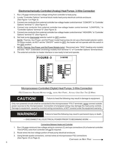
Electromechanically-Controlled (Analog) <strong>Heat</strong> <strong>Pumps</strong>: 3-Wire Connection<br />
1. Run (18-gage minimum) low-voltage wiring from controller <strong>to</strong> heat pump.<br />
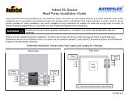
2. Locate “Controller Options” terminal block inside heat pump electrical controls enclosure<br />
(See Figure-1 on Page-3).<br />
3. Connect one conduc<strong>to</strong>r from external controller low-voltage heater control terminal: “COM/OFF,” <strong>to</strong> “Controller<br />
Options” terminal “C” (See Figure-3).<br />
4. Connect one conduc<strong>to</strong>r from external controller low-voltage heater control terminal: “LOW/POOL,” <strong>to</strong><br />
“Controller Options” terminal “D” (See Figure-3).<br />
5. Connect one conduc<strong>to</strong>r from external controller low-voltage heater control terminal: “HIGH/SPA,” <strong>to</strong> “Controller<br />
Options” terminal “E” (See Figure-3).<br />
6. Set heat pump thermostat selec<strong>to</strong>r switch <strong>to</strong> OFF position.<br />
NOTE: Thermie, Sun Power, and Sol Power model heat pumps do not use a thermostat selec<strong>to</strong>r switch.<br />
On these models, do NOT set the “ON/OFF” switch <strong>to</strong> OFF; the heater will not operate with this switch in<br />
the OFF position.<br />
7. NOTE- Thermie, Sun Power, and Sol Power Models (only): Disconnect wire :”W24” (heating only models)<br />
and wire: “W27” (Icebreaker (reversing) models) from terminal “C” of “Controller Options” terminal block.<br />
8. The external controller-<strong>to</strong>-heater interface is now ready <strong>to</strong> test and operate.<br />
FIGURE-3<br />
3-WIRE<br />
---------------------------------------------------------------------------------<br />
Microprocessor-Controlled (Digital) <strong>Heat</strong> <strong>Pumps</strong>: 3-Wire Connection<br />
FS-2 CONNECTION: REQUIRED METHOD FOR ALL DIGITAL HEAT PUMPS... ACTUALLY USES ONLY TWO (2) WIRES<br />
CAUTION!<br />
Failure <strong>to</strong> heed the following may result in damage <strong>to</strong> equipment.<br />
Only non-powered circuits shall be connected <strong>to</strong> the microprocessor “FS-2” terminals; never connect outside<br />
power sources <strong>to</strong> the microprocessor. Connection of energized wiring may damage the heat pump controls.<br />
Damage <strong>to</strong> equipment, caused by incorrect wiring connections, is NOT covered under the equipment warranty.<br />
WARNING!<br />
Failure <strong>to</strong> heed the following may result in permanent injury or death.<br />
— DISCONNECT ALL ELECTRICAL POWER PRIOR TO BEGINNING WORK —<br />
6<br />
Connections Between <strong>Heat</strong>er and Controller<br />
1. Run (18-gage minimum) low-voltage wiring <strong>to</strong> common (C) and spa connections (H) of external controller.<br />
Third (POOL) wire from controller will not be required.<br />
2. Route wires in<strong>to</strong> low-voltage portion of heat pump electrical enclosure.<br />
3. Using female spade connec<strong>to</strong>rs, connect wires at microprocessor FS2 connections<br />
(See Figure-1A on Page-3).<br />
CONTINUED ON NEXT PAGE