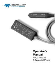
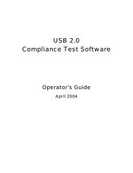
USB2.0 Compliance test Software Operator's ... - Teledyne LeCroy
USB2.0 Compliance test Software Operator's ... - Teledyne LeCroy
USB2.0 Compliance test Software Operator's ... - Teledyne LeCroy

Create successful ePaper yourself
Turn your PDF publications into a flip-book with our unique Google optimized e-Paper software.
USB2<br />
USB 2.0 <strong>Compliance</strong><br />
Test <strong>Software</strong><br />
For <strong>LeCroy</strong> X-Stream<br />
Scopes<br />
Operator’s Manual<br />
July 2003
USB2 Operation<br />
<strong>LeCroy</strong> Corporation<br />
700 Chestnut Ridge Road<br />
Chestnut Ridge, NY 10977-6499<br />
Tel: (845) 578 6020, Fax: (845) 578 5985<br />
Internet: www.lecroy.com<br />
© 2003 by <strong>LeCroy</strong> Corporation. All rights reserved.<br />
<strong>LeCroy</strong>, ActiveDSO, ProBus, SMART Trigger, WavePro, and Waverunner are registered trademarks<br />
of <strong>LeCroy</strong> Corporation. JitterTrack, WaveMaster, and X-Stream are trademarks of <strong>LeCroy</strong><br />
Corporation. Information in this publication supersedes all earlier versions. Specifications subject to<br />
change without notice.<br />
USB2-OM-E Rev A<br />
901692<br />
2 ISSUED: July 2003 USB2-OM-E Rev A
USB2 Operation<br />
USB 2.0 COMPLIANCE TEST PACKAGE...................................................................4<br />
USB2 Capabilities ...................................................................................................................4<br />
Getting Started........................................................................................................................6<br />
USB Test Fixture.....................................................................................................................7<br />
USB-IF Test Scripts.................................................................................................................7<br />
USB-IF High Speed Test Tool ...................................................................................................7<br />
MATLAB.................................................................................................................................8<br />
Performing USB <strong>Compliance</strong> Tests ...........................................................................................8<br />
Signal Quality Tests ................................................................................................................9<br />
Packet Parameters..................................................................................................................9<br />
Chirp Timing............................................................................................................................9<br />
Appendix A: USB-IF Host High-speed Electrical Test Procedure for <strong>LeCroy</strong><br />
Appendix B: USB-IF Device High-speed Electrical Test Procedure for <strong>LeCroy</strong><br />
Appendix C: USB-IF Hub High-speed Electrical Test Procedure for <strong>LeCroy</strong><br />
USB2-OM-E Rev A ISSUED: July 2003 3
USB2 Operation<br />
USB 2.0 COMPLIANCE TEST PACKAGE<br />
USB2 Capabilities<br />
<strong>LeCroy</strong>'s USB2 option is an automated <strong>test</strong> package that performs<br />
all the required <strong>test</strong>s from the USB-IF for physical layer<br />
compliance of USB 2.0 hosts, devices, and hubs. The package<br />
consists of software that runs inside the <strong>LeCroy</strong> WavePro 7300<br />
DSO, as well as the WaveMaster and SDA series of X-Stream<br />
digitizing oscilloscopes, and an optional <strong>test</strong> fixture that allows<br />
you to couple to the electrical USB signals.<br />
The software and fixture combined perform the following<br />
measurements for USB 2.0 hosts, devices, and hubs:<br />
Note:<br />
• USB2 – USB 2.0 physical<br />
layer compliance <strong>test</strong><br />
software<br />
• TF-USB – Test fixture for use<br />
with USB <strong>test</strong> software<br />
Host Tests<br />
• High-speed Signal Quality (far end/near end)<br />
• High-speed Packet Parameters<br />
• High-speed Chirp Timing<br />
• High-speed Suspend/Resume<br />
• High-speed Disconnect<br />
• Full-speed Downstream Signal Quality<br />
• Low-speed Downstream Signal Quality<br />
Device Tests<br />
• High-speed Signal Quality (far end/near end)<br />
• High-speed Packet Parameters<br />
• High-speed Chirp Timing<br />
• High-speed Suspend/Resume<br />
• Full-speed Signal Quality (upstream)<br />
• Low-speed Signal Quality (upstream)<br />
• Inrush current<br />
4 ISSUED: July 2003 USB2-OM-E Rev A
USB2 Operation<br />
Hub Tests<br />
• High-speed Signal Quality (upstream/downstream)<br />
• High-speed Downstream Jitter<br />
• High-speed Packet Parameters<br />
• High-speed Chirp Timing<br />
• High-speed Suspend/Resume<br />
• High-speed Disconnect<br />
• High-speed Repeater (upstream/downstream)<br />
• Full-speed Downstream Signal Quality<br />
• Low-speed Downstream Signal Quality<br />
• Droop<br />
In addition to the above <strong>test</strong>s, the J/K, SE0_NAK <strong>test</strong> can be<br />
performed with the use of a digital voltmeter. This <strong>test</strong> is performed<br />
for Hosts, Devices, and Hubs.<br />
Device receive sensitivity requires the use of a data generator to<br />
produce “IN” packets. This manual describes the use of both the<br />
Agilent 81130A pulse generator and the Tektronix DG2040A data<br />
pattern generator for this <strong>test</strong>, although other instruments can also<br />
be used.<br />
USB2-OM-E Rev A ISSUED: July 2003 5
USB2 Operation<br />
Getting Started<br />
The USB2 option is invoked by selecting “USB2” from the<br />
Analysis menu of the instrument. Once invoked, the USB 2.0 <strong>test</strong><br />
menu appears at the bottom of the instrument display. This menu<br />
serves both to control the various measurement modes and to<br />
guide you through the steps of the <strong>test</strong> procedure. The Reset,<br />
Back, and Next buttons navigate through each measurement.<br />
Specific measurements are selected from the Mode and Test<br />
menus.<br />
As the <strong>test</strong> procedure is followed by the software, setup panels<br />
are recalled automatically for each <strong>test</strong> and mode. These setup<br />
files are provided with the <strong>test</strong> software and are automatically<br />
installed in directory “D:\applications\USB2\setups. The following<br />
figure shows the contents of this directory. In addition to the setup<br />
directory, the files sigqual.tsv, sigqualPlot.png, sigqualEye.png,<br />
and sigqual.html may also be present. These four files are<br />
automatically generated during the signal quality <strong>test</strong>. The<br />
“sigqual.html” file is a report that summarizes the signal quality<br />
<strong>test</strong>. Results files are stored in directory<br />
D:\applications\USB2\results.<br />
6 ISSUED: July 2003 USB2-OM-E Rev A
USB2 Operation<br />
USB Test Fixture<br />
A USB <strong>test</strong> fixture (TF-USB) is required to perform compliance<br />
<strong>test</strong>s. The fixture consists of several sections that are designed to<br />
allow connection to the electrical signal under <strong>test</strong>. Each section<br />
is marked on the fixture and the ports on each section are also<br />
labeled. The section and port(s) to use for a given <strong>test</strong> are called<br />
out in the procedure on the instrument screen. A 5 V power supply<br />
(provided with the fixture) is required in order for the fixture to<br />
operate.<br />
USB-IF Test Scripts<br />
The <strong>test</strong> package uses <strong>test</strong> scripts written by the USB<br />
Implementers Forum (USB-IF) specifically for analyzing <strong>test</strong> data<br />
acquired by the oscilloscope. These scripts are used by the <strong>test</strong><br />
software. The scripts are installed in directory C:\Program<br />
Files\USB-IF Test Suite\USB HS Electrical Test Toolkit\Analysis<br />
Tools\MatlabPcode when the USB-IF <strong>test</strong> suite is installed. The<br />
software USBHSET.exe can be downloaded from the UFB-IF web<br />
site at www.USB-IF.org. These files must be in the above directory<br />
on the oscilloscope. The USB-IF software on both the host<br />
computer and the oscilloscope is the same code that is<br />
downloaded from the USB-IF web site.<br />
USB-IF High Speed Test Tool<br />
A host computer with a USB 2.0 controller card is required to run<br />
the USB compliance <strong>test</strong>s. This computer must be running<br />
Windows 2000 Professional and must have installed on it the<br />
USB-IF <strong>test</strong> suite described above. The instructions in the <strong>LeCroy</strong><br />
<strong>test</strong> package will prompt you to execute specific functions within<br />
the USB High Speed <strong>test</strong> tool on the host computer for various<br />
<strong>test</strong>s.<br />
USB2-OM-E Rev A ISSUED: July 2003 7
USB2 Operation<br />
MATLAB<br />
Performing USB <strong>Compliance</strong> Tests<br />
The <strong>LeCroy</strong> USB 2.0 <strong>test</strong> suite requires MATLAB in order to<br />
operate. A 30-day free trial is shipped with each <strong>LeCroy</strong><br />
oscilloscope. Contact The Math Works to activate a permanent<br />
version at www.mathworks.com. MATLAB scripts are used to<br />
perform signal quality <strong>test</strong>s.<br />
Depending upon the <strong>test</strong> being performed (Host, Device, or Hub),<br />
you will need a host computer with a USB 2.0 controller, a <strong>test</strong><br />
fixture, and a device. The general setup is shown in the figure<br />
below. Connections between the device, host, and fixture are<br />
made with USB cables or captive cables on the fixture, depending<br />
upon the <strong>test</strong>. Step-by-step procedures for each <strong>test</strong> appear on<br />
the oscilloscope display, as well as in an appendix to this manual.<br />
The following sections of this manual will give an overview of each<br />
<strong>test</strong>.<br />
USB <strong>test</strong><br />
fixture<br />
device<br />
host<br />
DSO<br />
8 ISSUED: July 2003 USB2-OM-E Rev A
USB2 Operation<br />
Signal Quality Tests<br />
Signal quality <strong>test</strong>s are required for hosts, devices, and hubs<br />
operating at high, full, and low speeds. The <strong>LeCroy</strong> USB <strong>test</strong><br />
solution uses the USB-IF signal quality <strong>test</strong> scripts to perform<br />
these <strong>test</strong>s. Signal quality <strong>test</strong>s include:<br />
• Eye pattern<br />
• Signal rate<br />
• Consecutive jitter<br />
• EOP width<br />
• Crossover voltage<br />
• Rise time<br />
• Fall time<br />
• Monotonicity (HS only)<br />
• Paired J/K jitter<br />
• Paired K/J jitter<br />
The letters J and K refer to ‘1’ and ‘0’ states on the USB cable<br />
respectively. This terminology is used because the high-speed<br />
driver circuits are current-steering devices that signal bit values<br />
through the direction of current flow through a loop formed by the<br />
USB cable and terminating resistors in the receiver. The voltage<br />
drop is measured across terminating resistors in the <strong>test</strong> fixture.<br />
Packet Parameters<br />
Packet parameters represent the timing measurements of the<br />
communications between host, hub, and device. USB 2.0<br />
transmits data in packets that are transferred over the same pair of<br />
wires. Therefore, the timing of these packets is critical for proper<br />
communications. The width of the EOP (end of packet) and the<br />
inter-packet timing is measured in this step.<br />
Chirp Timing<br />
A high-speed USB port must also be compatible with low- and fullspeed<br />
operation (12 and 1.2 Mb/s). High-speed operation is<br />
detected using the K and J chirp. Low- and full-speed operation<br />
use a higher impedance load. When the high-speed current is<br />
USB2-OM-E Rev A ISSUED: July 2003 9
USB2 Operation<br />
applied to this load, the receiving port must disable its LS/FS load<br />
and apply the specified high-speed loads to the D+ and D- lines.<br />
The resulting voltage shift or “chirp” must occur within a specified<br />
time indicating that the port has correctly detected the switch to<br />
high-speed operation.<br />
§ § §<br />
10 ISSUED: July 2003 USB2-OM-E Rev A
Host HS Tests for <strong>LeCroy</strong><br />
Universal Serial Bus<br />
Implementers Forum<br />
Host High-speed<br />
Electrical Test Procedure For<br />
<strong>LeCroy</strong><br />
Revision 0.9<br />
May 23, 2003<br />
USB2-OM-E Rev A ISSUED: July 2003 1
Host HS Tests for <strong>LeCroy</strong><br />
Revision History<br />
Rev Date Filename Comments<br />
0.9<br />
(Beta)<br />
May-23-2003 Host HS Test for lecroy.DOC Primary version of High Speed Test Procedure adapted to<br />
Agilent <strong>test</strong> equipment based on the <strong>test</strong> procedure created<br />
by USB-IF (version 0.9)<br />
Please send comments via electronic mail to techsup©usb.org<br />
USB-IF High-speed Electrical Test Procedure<br />
© Copyright 2001, USB Implementers Forum, Inc.<br />
All rights reserved.<br />
USB2-OM-E Rev A ISSUED: July 2003 2
Host HS Tests for <strong>LeCroy</strong><br />
DISCLAIMER OF WARRANTIES<br />
THIS SPECIFICATION IS PROVIDED “AS IS” AND WITH NO WARRANTIES OF ANY KIND,<br />
EXPRESS OR IMPLIED, INCLUDING, WITHOUT LIMITATION, NO WARRANTY OF<br />
NONINFRINGEMENT, NO WARRANTY OF MERCHANTABILITY, NO WARRANTY OF<br />
FITNESS FOR A PARTICULAR PURPOSE, NO WARRANTY OF TITLE, AND NO WARRANTY<br />
ARISING OUT OF ANY PROPOSAL, SPECIFICATION, OR SAMPLE, ALL OF WHICH<br />
WARRANTIES ARE EXPRESSLY DISCLAIMED.<br />
WITHOUT LIMITING THE GENERALITY OF THE FOREGOING, USB-IF AND THE AUTHORS<br />
OF THE SPECIFICATION DO NOT WARRANT OR REPRESENT THAT USE OF THE<br />
SPECIFICATION WILL NOT INFRINGE THE INTELLECTUAL PROPERTY RIGHTS OF<br />
OTHERS. USERS OF THE SPECIFICATIONASSUME ALL RISK OF SUCHINFRINGEMENT,<br />
AND AGREE THAT THEY WILL MAKE NO CLAIM AGAINST USB-IF OR THE AUTHORS IN<br />
THE EVENT OF CLAIMS OF INFRINGEMENT.<br />
USB-IF IS NOT LIABLE FOR ANY CONSEQUENTIAL, SPECIAL OR OTHER DAMAGES ARISING OUT OF<br />
THE USE OF THE SPECIFICATION.<br />
LICENSE FOR INTERNAL USE ONLY<br />
USB-IF HEREBY GRANTS A LICENSE TO REPRODUCE AND TO DISTRIBUTE THIS<br />
SPECIFICATION FOR INTERNAL USE ONLY. NO OTHER LICENSE, EXPRESS OR IMPLIED,<br />
BY ESTOPPEL OR OTHERWISE, IS GRANTED HEREWITH, AND NO LICENSE OF<br />
INTELLECTUAL PROPERTY RIGHTS IS GRANTED HEREWITH.<br />
All product names are trademarks, registered trademarks, or servicemarks of their respective owners.<br />
USB2-OM-E Rev A ISSUED: July 2003 3
Host HS Tests for <strong>LeCroy</strong><br />
Table of Contents<br />
Introduction 5<br />
2 Purpose 5<br />
3 Equipment Required 5<br />
3.1 EquipmentSetup 6<br />
3.1.1 <strong>LeCroy</strong> Digital Sampling Oscilloscope 6<br />
3.2 Operating Systems, <strong>Software</strong>, Drivers, and Setup Files 7<br />
3.2.1 Operating Systems 7<br />
3.3 Special Purpose <strong>Software</strong> 7<br />
3.3.1 Test Equipment Setup Files 8<br />
4 Test Procedure 8<br />
4.1 Test Record 8<br />
4.2 Vendor and Product Information 8<br />
4.3 Legacy USB <strong>Compliance</strong> Tests 9<br />
4.4 Host High-speed Signal Quality (EL_2, EL_3, EL_6, EL_7) 9<br />
4.5 Host Controller Packet Parameters (EL_21, EL_22, EL_23, EL_25, EL_55) 15<br />
4.6 Host Disconnect Detect (EL_36, EL_37) 19<br />
4.7 Host CHIRP Timing (EL_33, EL_34, EL_35) 21<br />
4.8 Host Suspend/Resume timing (EL_39, EL_41) 23<br />
4.9 Host Test J/K, SE0_NAK (EL_8, EL_9) 25<br />
A.4 Host High-speed Electrical Test Data 29<br />
A.4.2 Vendor and Product Information 29<br />
A.4.3 Legacy USB <strong>Compliance</strong> Tests 30<br />
A.4.4 Host High-speed Signal Quality (EL_2, EL_3, EL_6, EL_7) 30<br />
A.4.5 Host Controller Packet Parameters (EL_21, EL_22, EL_23, EL_25, EL_55) 32<br />
A.4.6 Host Disconnect Detect (EL_36, EL_37) 33<br />
A.4.7 Host CHIRP Timing (EL_33, EL_34, EL_35) 34<br />
A.4.8 Host Suspend/Resume timing (EL_39, EL_41) 35<br />
A.4.9 Host Test J/K, SE0_NAK (EL_8, EL_9) 35<br />
USB2-OM-E Rev A ISSUED: July 2003 4
Host HS Tests for <strong>LeCroy</strong><br />
I<br />
Introduction<br />
The USB-IF High-speed Electrical Test Procedures are developed by the USB 2.0 <strong>Compliance</strong><br />
Committee under the direction of USB-IF, Inc. There are three High-speed Electrical Test<br />
Procedures. The Host High-speed Electrical Test Procedure is for EHCI host controllers. The Hub<br />
High-speed Electrical Test Procedure is for high-speed capable hubs. The Device High-speed<br />
Electrical Test Procedure is for high-speed capable devices.<br />
The High-speed Electrical <strong>Compliance</strong> Test Procedures verify the electrical requirements of high-speed USB<br />
operation of these devices designed to the USB 2.0 specification. In addition to passing the high-speed <strong>test</strong><br />
requirements, high-speed capable products must also complete and pass the applicable legacy compliance <strong>test</strong>s<br />
identified in these documents in order to be posted on the USB-IF Integrators List and use the USB-IF logo in<br />
conjunction with the said product (if the vendor has signed the USB-IF Trademark License Agreement). These<br />
legacy compliance <strong>test</strong>s are identified in the Legacy USB <strong>Compliance</strong> Test section in this document.<br />
2 Purpose<br />
This USB-IF High-speed Electrical Test Procedure documents a series of <strong>test</strong>s used to evaluate USB peripherals and<br />
systems operating at high-speed. These <strong>test</strong>s are also used to evaluate the high-speed operation of USB silicon that<br />
has been incorporated in ready-to-ship products, reference designs, proofs of concept and one of a kind prototypes of<br />
peripherals, add-in cards, motherboards, or systems.<br />
This <strong>test</strong> procedure makes reference to the <strong>test</strong> assertions in the USB-IF <strong>USB2.0</strong> Electrical Test Specification,<br />
Version 1.00.<br />
This Host USB-IF High-speed Electrical Test Procedure is one of the three USB-IF High-speed<br />
Electrical <strong>Compliance</strong> Test Procedures. The other two are Hub USB-IF High-speed Electrical Test<br />
Procedure and Device USB-IF High-speed Electrical Test Procedure. The adoption of the<br />
individual procedures based on the device class makes it easier to use.<br />
3 Equipment Required<br />
The commercial <strong>test</strong> equipment listed here are based on positive experience by the USB-IF members in executing<br />
the USB high-speed electrical <strong>test</strong>s. This <strong>test</strong> procedure is written with a set of specific models we use to develop<br />
this procedure. In time, there will be other equivalent or better <strong>test</strong> equipment suitable for use. Some minor<br />
adaptation of the procedure will be required in those cases.<br />
• Digital Storage Oscilloscope:<br />
• WaveMaster, SDA, or WavePro7300 Digital oscilloscope from <strong>LeCroy</strong> Corporation<br />
• <strong>LeCroy</strong> AP034 or equivalent differential probe, qty = 1<br />
• <strong>LeCroy</strong> HFP2500 Active probe, qty = 2<br />
• 3 1/2 Digital Multimeter — Agilent 972A or equivalent<br />
• Mini-clip DMM lead - one each of black and red color<br />
USB2-OM-E Rev A ISSUED: July 2003 5
Host HS Tests for <strong>LeCroy</strong><br />
• High-speed USB Electrical Test Fixtures<br />
• <strong>LeCroy</strong> USB 2.0 <strong>test</strong> fixture or equivalent, qty = 1<br />
• Miscellaneous Cables<br />
• 1M USB cable, qty = 1<br />
• 1.5M USB cable, qty = 1<br />
• Modular AC power cord, qty = 2<br />
• High-speed USB Test Bed Computer<br />
This is the computer that hosts a USB 2.0 compliance host controller for high-speed hub or device electrical <strong>test</strong>, or<br />
serves as a <strong>test</strong> bed host for a USB 2.0 host controller under <strong>test</strong>. This OS on this computer is Windows 2000<br />
Professional. Please refer to the High-speed Electrical Test Setup Instruction for steps to configure this computer.<br />
3.1 Equipment Setup<br />
3.1.1 <strong>LeCroy</strong> WaveMaster, SDA or WavePro7300<br />
Before turning on the oscilloscope, attach the AP034 probe to Channel-1. Make sure the 10x attenuator is attached at<br />
the tip of the differential probe. Attach the HFP2500 probes to channels 2 and 3. These probe assignments will be<br />
used through out the entire <strong>test</strong> procedure. Turn on the oscilloscope to allow for 10 minutes of warm up time prior to<br />
use.<br />
Note: In certain <strong>test</strong> situations, there may not be a ground connection between the DSO and the device under <strong>test</strong>.<br />
This may lead to the signal seen by the differential probe to be modulated up and down due to mid frequency<br />
switching power supply. Connecting the DSO ground to the DUT ground will be require to establish a common<br />
ground reference.<br />
3.2 Operating Systems, <strong>Software</strong>, Drivers, and Setup Files<br />
3.2.1 Operating Systems<br />
Microsoft Windows 2000 Professional is required on the High-speed Electrical Test Bed<br />
Computer. Microsoft Windows 2000 Professional is required on the High-speed Signal Quality<br />
Analysis Computer. Please refer to the High-speed Electrical Test Setup Instruction for steps to<br />
configure these computers.<br />
3.3 Special Purpose <strong>Software</strong><br />
The following special purpose software is required. Please refer to the High-speed Electrical Test Setup Instruction<br />
for steps to configure these computers.<br />
• High-speed Electrical Test Tool <strong>Software</strong> — To be used in the High-speed Electrical Test Bed<br />
Computer.<br />
• Proprietary EHCI Driver Stack - The High-speed Electrical Test Tool software requires the use of a<br />
proprietary EHCI driver stack. The use of this proprietary EHCI driver stack facilitates the<br />
electrical <strong>test</strong>ing that requires direct control of the command registers of the USB EHCI host<br />
USB2-OM-E Rev A ISSUED: July 2003 6
Host HS Tests for <strong>LeCroy</strong><br />
controllers. The end result much more robust <strong>test</strong> bed environment. Since the proprietary EHCI<br />
driver stack is designed for debug and <strong>test</strong> validation purposes, this driver stack does not support<br />
the normal functionality as found in the EHCI drivers from Microsoft (or the device vendor). An<br />
automatic driver stack switching function has been implemented into the High-speed Electrical<br />
Test Tool for easy switching between the proprietary EHCI driver stack and that from Microsoft.<br />
Upon invocation of the HS Electrical Test Tool software, the driver stack will automatically switch<br />
to the Intel proprietary EHCI driver stack. Upon exit of the HS Electrical Test Tool software, the<br />
driver stack will automatically switch to the Microsoft EHCI driver stack.<br />
• <strong>LeCroy</strong> <strong>USB2.0</strong> <strong>test</strong> software for the WaveMaster, SDA or WavePro<br />
4 Test Procedure<br />
4.1 Test Record<br />
Appendix A contains the <strong>test</strong> result entry form for this <strong>test</strong> procedure. Please make copies of the Appendix A for use<br />
as <strong>test</strong> record documentation for compliance <strong>test</strong> submission. All fields must be filled in. Fields not applicable for<br />
the device under <strong>test</strong> should be indicated as N/A, with appropriate note explaining the reason. The completed <strong>test</strong><br />
result shall be retained for the compliance <strong>test</strong> submission.<br />
In addition to the hardcopy <strong>test</strong> record, the electronic files from the signal quality, and power delivery (inrush, drop<br />
and droop) shall be retained for compliance <strong>test</strong> submission.<br />
4.2 Vendor and Product Information<br />
Collect the following information and enter into a copy of the <strong>test</strong> record in Appendix A before performing any<br />
<strong>test</strong>s.<br />
1. Test date<br />
2. Vendor name<br />
3. Vendor address and phone, and the contact name<br />
4. Test submission ID number<br />
5. Product name<br />
6. Product model and revision<br />
7. USB silicon vendor name<br />
8. USB silicon model<br />
9. USB silicon part marking<br />
10. USB silicon stepping<br />
11. Test conducted by<br />
USB2-OM-E Rev A ISSUED: July 2003 7
Host HS Tests for <strong>LeCroy</strong><br />
4.3 Legacy USB <strong>Compliance</strong> Tests<br />
In addition to the high-speed electrical <strong>test</strong>s prescribed in this document, the host controller under <strong>test</strong> must also pass<br />
the following compliance <strong>test</strong>s applicable to the EHCI Host Controller:<br />
• Low speed signal quality<br />
• Full speed signal quality<br />
• Drop/Droop<br />
• Interoperability<br />
Perform all these <strong>test</strong>s and record the measurements and summarized Pass/Fail status in Appendix A.<br />
4.4 Host High-speed Signal Quality (EL_2, EL_3, EL_6, EL_7)<br />
1. Turn on the oscilloscope if have not already done so. Allow about 10 minutes for warm up. Attach a AP034 or<br />
equivalent differential probe to channel 1 of the oscilloscope. Attach a 10X attenuator to the end of the<br />
differential probe.<br />
2. Select USB2 from the Analysis menu on the oscilloscope. In the USB Test Wizard, select Host mode and HS<br />
FE Signal Quality for the <strong>test</strong> if there is to be a cable between the <strong>test</strong> fixture and the high speed port under <strong>test</strong><br />
or HS NE Signal Quality if the fixture is connected directly to the port under <strong>test</strong>.<br />
3. Attach the 5V power supply to J2 of the <strong>test</strong> fixture and verify the yellow Power LED (D2) is lit.<br />
4. Attach the differential probe to J30 of the Host Signal Quality section of the <strong>test</strong> fixture. Ensure + on probe lines<br />
up with D+ on fixture.<br />
5. Invoke the High-speed Electrical Test Tool software on the High-speed Electrical Test Bed computer. The main<br />
USB2-OM-E Rev A ISSUED: July 2003 8
Host HS Tests for <strong>LeCroy</strong><br />
menu appears and shows the <strong>USB2.0</strong> host controller.<br />
6. Select Host Controller/System and click the [TEST] button to enter the Host Test menu.<br />
7. Connect the [TEST PORT] of the Host High-speed Signal Quality <strong>test</strong> section of the fixture into the port under<br />
<strong>test</strong> of the Host controller.<br />
8. Select TEST_PACKET from the Port Control drop down menu. Enter the port number of the port being <strong>test</strong>ed<br />
and click [EXECUTE]. This forces the port under <strong>test</strong> to continuously transmit <strong>test</strong> packets.<br />
9. Enter a descriptive file name in the [Result File Name] dialog box. Note that the default directory is<br />
D:\Applications\USB2\Results and the file name has the extension *.tsv which is the intermediate result file for<br />
the MatLab scripts. The same file name (with an .HTM extension) is used for the HTML report file.<br />
10. Press the [Next] key in the <strong>LeCroy</strong> USB 2.0 <strong>test</strong> wizard. The MatLab analysis script will be invoked to measure<br />
the signal quality. The following two plots, which can be viewed by minimizing the oscilloscope application<br />
(File, Minimize) or by pressing Atl/Tab on the keyboard attached to the oscilloscope, will appear on the<br />
Windows desktop:<br />
USB2-OM-E Rev A ISSUED: July 2003 9
Host HS Tests for <strong>LeCroy</strong><br />
14. The results displayed are also recorded to an HTML report located in the directory specified in the “Data Path”<br />
control in the <strong>test</strong> wizard (D:\Applications\USB2\Results by default). Open this file and verify the Signal eye,<br />
EOP Width, and Signaling Rate all pass<br />
18. Record the <strong>test</strong> result in EL_2, EL_3, EL_6, and EL_7.<br />
19. Remove the Host Signal Quality <strong>test</strong> fixture from the port.<br />
20. Repeat steps 7 through 14 for all remaining ports.<br />
21. Save all files created during the <strong>test</strong>s. To ensure that all of the results are saved, change the name in the Result<br />
File Name dialog box in the <strong>test</strong> wizard before each port is <strong>test</strong>ed. Remove the Host Signal Quality <strong>test</strong> fixture<br />
from the host controller.<br />
4.5 Host Controller Packet Parameters (EL_21, EL_22, EL_23, EL_25,<br />
EL_55)<br />
USB2-OM-E Rev A ISSUED: July 2003 10
Host HS Tests for <strong>LeCroy</strong><br />
1. Select Host in the Mode control and HS Packet Parameters in the Test control of the USB Test Wizard.<br />
2. Connect the Device Signal Quality section of the <strong>test</strong> fixture ([TEST PORT]) into B receptacle of a known<br />
good high-speed hub. Apply power to the known good hub (refered to as device herein).<br />
Note: The use of the Device High-speed Signal Quality <strong>test</strong> fixture makes it possible to trigger on packets generated<br />
by the device because the differential probe is located closer to the device transmitter, hence the device packets are<br />
larger in amplitude.<br />
3. Attach the differential probe to J19 on the fixture near the device connector. Ensure + on probe lines up<br />
with D+ on fixture.<br />
4. Connect the Device Signal Quality section of the <strong>test</strong> fixture ([INIT PORT]) into the host controller port<br />
under <strong>test</strong>. Click [Enumerate Bus] and verify that the device enumerates properly.<br />
5. In the Host Test menu of the High-speed Electrical Test Tool software, ensure the device is selected<br />
(highlighted). Select SINGLE STEP GET DEV DESC from the Downstream Device Control menu and<br />
click [EXECUTE] once.<br />
6. The oscilloscope capture should appear as follows.<br />
7. P1 indicates the sync field length in bits which should indicate 31 edges which corresponds to 32 bits.<br />
Record the number (P1 + 1) in EL_21.<br />
USB2-OM-E Rev A ISSUED: July 2003 11
Host HS Tests for <strong>LeCroy</strong><br />
8. Press Next in the <strong>test</strong> wizard to measure the EOP length (number of bits) of the second packet on the<br />
oscilloscope and verify that it is 8 bits per EL_25. This result is shown in P1 and P2. The <strong>test</strong> passes if<br />
either one is 8 bits since the EOP can appear as negative or positive going pulses. Record the result in<br />
EL_25.<br />
9. Press Next in the <strong>test</strong> wizard to measure the inter-packet gap between the first two packets shown on the<br />
oscilloscope by. The requirement is it must be between 88 bits and 192 bits (EL_23). This result is shown<br />
in P1 and P2 for negative and positive going pulses respectively. Record this value in EL_23. The<br />
oscilloscope should appear as shown in the following figure.<br />
10. Measure the inter-packet gap between the second and the third packets by pressing the Next button on the<br />
<strong>test</strong> wizard. This value is reported in P1 and P2. The requirement is it must be between 8 bits and 192 bits.<br />
(EL_22). Record the computed number of bits in EL_22.<br />
USB2-OM-E Rev A ISSUED: July 2003 12
Host HS Tests for <strong>LeCroy</strong><br />
11. On the HS Test Tool, press Step twice and then Enumerate Bus.<br />
12. Press the Next button in the <strong>test</strong> wizard to measure the SOF EOP width. This value is reported in P1 and<br />
P2. The requirement is that either the negative (P1) or positive (P2) must be 40 bits (83.2 ns). Record the<br />
result in EL_55.<br />
13. Repeat step 4 through 12 for the remaining ports.<br />
14. Remove the Device Signal Quality <strong>test</strong> fixture and the known good device from the host controller port<br />
under <strong>test</strong>.<br />
4.6 Host Disconnect Detect (EL_36, EL_37)<br />
This section uses the Disconnect <strong>test</strong> fixture to verify the disconnect thresholds of the port under <strong>test</strong> by simulated<br />
disconnect condition.<br />
When the TEST switch on the <strong>test</strong> fixture is in the Test position, the port under <strong>test</strong> is subjected to a threshold<br />
Host HS Tests for <strong>LeCroy</strong><br />
When the TEST switch is in the Normal position, the port under <strong>test</strong> is subjected to a threshold<br />
>625mV. The port should detect a disconnection.<br />
1. Attach the 5V power supply to <strong>test</strong> fixture (J2).<br />
2. Select Host in the Mode control and HS Disconnect in the Test control of the USB Test Wizard.<br />
3. Attach the differential probe to J5 of the disconnect section of the fixture. Ensure the + tip on probe lines up<br />
with D+ on the fixture.<br />
4. Set the two switches in the disconnect section away from the TEST and LOW positions. This sets the <strong>test</strong><br />
fixture to emulate a must-not-disconnect threshold.<br />
5. Attach the [INIT] dongle of the disconnect section of the <strong>test</strong> fixture to the port under <strong>test</strong>. In the Host Test<br />
menu of the High-speed Electrical Test Tool software select TEST_FORCE_ENABLE from the Port<br />
Control window. Enter the port number and click [EXECUTE] once and ensure the operation is successful<br />
in the Status Window.<br />
6. Click the Disconnect Notify check box to monitor the disconnect status in the Status Window.<br />
7. Using the oscilloscope, verify the SOF packets are being transmitted from the port under <strong>test</strong>. The<br />
differential amplitude should be less than +/- 525mV (1.05V p-p). Verify that the Status Window does not<br />
display Disconnect Event Detected. Record the pass/fail result in EL_37.<br />
USB2-OM-E Rev A ISSUED: July 2003 14
Host HS Tests for <strong>LeCroy</strong><br />
8. Move the TEST switch of the Disconnect section of the <strong>test</strong> fixture from its current position and press the<br />
Next button on the <strong>test</strong> wizard.<br />
9. Use the oscilloscope to monitor the differential amplitude of the SOF. It should be greater than +/- 625mV<br />
(1.25V p-p). Verify that the Status Window now displays the Disconnect Event Detected. Record the<br />
pass/fail result in EL_36<br />
USB2-OM-E Rev A ISSUED: July 2003 15
Host HS Tests for <strong>LeCroy</strong><br />
10. Return the TEST switch on the disconnect section of the fixture back to its original position.<br />
11. Repeat step 4 through 9 for all the remaining ports.<br />
12. Remove the Disconnect <strong>test</strong> fixture from the port under <strong>test</strong> before proceeding.<br />
4.7 Host CHIRP Timing (EL_33, EL_34, EL_35)<br />
1. Select Host in the Mode control and HS Chirp Timing in the Test control of the USB Test Wizard.<br />
2. Connect the HS port under <strong>test</strong> to the [INIT] port of the SQ Device section of the <strong>test</strong> fixture. Attach a<br />
known good device to the Device port of the SQ Device section of the <strong>test</strong> fixture. Apply power to the<br />
known-good device. Make sure the TEST/INIT switch is in the INIT position.<br />
3. Start the HS <strong>test</strong> tool, select Host Controller/System and push Test. Click [Enumerate Bus].<br />
4. Connect the HFP2500 probes from channel 2 to D- of J19 on the <strong>test</strong> fixture and channel 3 to D+ of J19.<br />
Press Next in the <strong>test</strong> wizard.<br />
5. On the HS <strong>test</strong> tool, select Enumerate bus and measure the host’s Chirp response timing. This is the time<br />
between the device’s de-assertion of Chirp-K and the start of alternate Chirp-K and Chirp-J sent by the<br />
host. The value of P1 indicates the chirp timing. Verify this timing is = 100uS. Record the result in EL_33.<br />
USB2-OM-E Rev A ISSUED: July 2003 16
Host HS Tests for <strong>LeCroy</strong><br />
6. Unplug and re-plug the known-good device from the fixture and press Next in the <strong>test</strong> wizard.<br />
7. Press Enumerate Bus on the HS <strong>test</strong> tool and measure the durations of the individual Chirp-K and Chirp-J<br />
states. These values are shown in P1 and P2 respectively and should be between 40 and 60 us (EL_31).<br />
Record the measurement in EL_34.<br />
USB2-OM-E Rev A ISSUED: July 2003 17
Host HS Tests for <strong>LeCroy</strong><br />
8. Unplug and re-plug the known good device from the <strong>test</strong> fixture and press Next in the <strong>test</strong> wizard.<br />
9. Press Enumerate Bus in the HS <strong>test</strong> tool.<br />
10. The chirp J/K to SOF time is indicated by P1. This value should be between 100 and 500us. Record this<br />
value in EL_35.<br />
USB2-OM-E Rev A ISSUED: July 2003 18
Host HS Tests for <strong>LeCroy</strong><br />
11. Repeat step 2 through 10 for the remaining down stream facing ports.<br />
4.8 Host Suspend/Resume timing (EL_39, EL_41)<br />
1. Select Host in the Mode control and HS Suspend Resume in the Test control of the USB Test Wizard.<br />
2. Connect the HS port under <strong>test</strong> to the [INIT] port of the SQ Device section of the <strong>test</strong> fixture. Attach a<br />
known good device to the Device port of the SQ Device section of the <strong>test</strong> fixture. Apply power to the<br />
known-good device. Make sure the TEST/INIT switch is in the INIT position.<br />
3. Start the HS <strong>test</strong> tool, select Host Controller/System and push Test. Click [Enumerate Bus].<br />
4. Connect the HFP2500 probes from channel 2 to D- of J19 on the <strong>test</strong> fixture and channel 3 to D+ of J19.<br />
Press Next in the <strong>test</strong> wizard.<br />
5. On the Host Test menu, select SUSPEND from the Port Control drop down menu and enter the port<br />
number. Click [EXECUTE] once to place the port into suspend. The captured suspend transition should<br />
appear as in the figure below.<br />
USB2-OM-E Rev A ISSUED: July 2003 19
Host HS Tests for <strong>LeCroy</strong><br />
6. The parameter P1 shows the time interval from the end of last SOF packet issued by the host to when the<br />
device attached its full speed pull-up resistor on D+ (transition to full speed J-state). This time should be<br />
between 3.000mS and 3.12Sms. Record the Pass/Fail result in EL_39.<br />
7. Press Next in the <strong>test</strong> wizard.<br />
8. On the Host Test menu, select RESUME from the Port Control drop down menu and enter the port number.<br />
Click [EXECUTE] once to resume the port. The captured suspend transition should appear as in the figure<br />
below.<br />
USB2-OM-E Rev A ISSUED: July 2003 20
Host HS Tests for <strong>LeCroy</strong><br />
9. The parameter P1 measures the time from the falling edge of D+ to the first SOF issued by the host<br />
(EL_41) as shown in the figure above. The value should be less that 3ms. Record the result in EL_41.<br />
Note: Repeat the suspend and resume a number of times and verify the time from the falling edge of D+ to the<br />
first SOF issued by the host never exceeds 3ms.<br />
10. Repeat step 4 through 9 for all the remaining ports.<br />
11. Unplug the know-good device from the <strong>test</strong> fixture. Click [Enumerate Bus] once before proceeding.<br />
Remove the FET probes from the <strong>test</strong> fixture.<br />
USB2-OM-E Rev A ISSUED: July 2003 21
Host HS Tests for <strong>LeCroy</strong><br />
4.9 Host Test J/K, SE0_NAK (EL_8, EL_9)<br />
1. Attach the dongle of the SQ Host section of the <strong>test</strong> fixture to the port under <strong>test</strong>.<br />
2. Select TESTJ from the Port Control drop down menu. Enter the port number and click [EXECUTE] once<br />
to place the port under <strong>test</strong> into TESTJ <strong>test</strong> mode.<br />
3. Using a DVM measure the DC voltage on the D+ line at J30 with respect to ground (the outside pins of J30<br />
are ground pins). Record in section EL_8.<br />
4. Using a DVM measure the DC voltage on the D- line at J7 with respect to ground. Record in section EL_8.<br />
5. On the Host Test menu, select TEST_K from the Port Control drop down menu. Enter the port number and<br />
click [EXECUTE] once to place the port under <strong>test</strong> into TEST_K <strong>test</strong> mode.<br />
6. Using a DVM measure the DC voltage on the D- line at J30 with respect to ground (the outside pins of J30<br />
are ground pins). Record in section EL_8.<br />
7. Using a DVM measure the DC voltage on the D+ line at J30 with respect to ground. Record in section<br />
EL_8.<br />
8. On the Host Test menu, select TEST_SE0_NAK from the Port Control drop down menu. Enter the port<br />
number and click [EXECUTE] once to place the port under <strong>test</strong> into TEST_SE0_NAK <strong>test</strong> mode.<br />
USB2-OM-E Rev A ISSUED: July 2003 22
Host HS Tests for <strong>LeCroy</strong><br />
9. Using a DVM measure the DC voltage on the D+ line at J30 with respect to ground (the outside pins of J30<br />
are ground pins). Record in section EL_9.<br />
10. Using a DVM measure the DC voltage on the D- line at J30 with respect to ground (the outside pins of J30<br />
are ground pins). Record in section EL_9.<br />
11. Repeat step 1 through 10 for the remaining ports.<br />
USB2-OM-E Rev A ISSUED: July 2003 23
Host HS Tests for <strong>LeCroy</strong><br />
Appendix A<br />
A.4 Host High-speed Electrical Test Data<br />
This section is for recording the actual <strong>test</strong> result. Please use a copy for each device to be <strong>test</strong>ed.<br />
A.4.2Vendor and Product Information<br />
Test Date<br />
Vendor Name<br />
Vendor Complete<br />
Address<br />
Vendor Phone Number<br />
Vendor Contact, Title<br />
Test ID Number<br />
Product Name<br />
Product Model and<br />
Revision<br />
USB Silicon Vendor<br />
Name<br />
USB Silicon Model<br />
USB Silicon Part Marking<br />
USB Silicon Stepping<br />
Tested By<br />
Please fill in all fields. Please contact your silicon supplier if you<br />
are unsure of the silicon information.<br />
29<br />
For Review and Discussion Only<br />
Draft Document Subject to Revision or Rejection<br />
Not For Publication or General Distribution<br />
Host High Speed Electrical Test Procedure for Agilent Infiniium Revision 1.0<br />
USB2-OM-E Rev A ISSUED: July 2003 24
Host HS Tests for <strong>LeCroy</strong><br />
A.4.3 Legacy USB <strong>Compliance</strong> Tests<br />
Legacy USB <strong>Compliance</strong> Checklist<br />
Legacy Test<br />
LS SQ<br />
FS SQ<br />
Drop/<br />
Droop<br />
Interop<br />
P = PASS<br />
F = FAIL<br />
Downstream Ports<br />
P1 P2 P3 P4 P5<br />
Comments<br />
N/A = Not applicable<br />
A.4.4 Host High-speed Signal Quality (EL_2, EL_3, EL_6, EL_7)<br />
EL_2 A USB 2.0 high-speed transmitter data rate must be 480 Mb/s ±0.05%.<br />
Reference documents: USB 2.0 Specification, Section 7.1.2.2.<br />
Port P1 P2 P3 P4 P5<br />
PASS<br />
FAIL<br />
NA<br />
Overall Result:<br />
Pass<br />
Fail<br />
N/A<br />
Comments:<br />
EL_3 A USB 2.0 downstream facing port must meet Template 1 transform waveform requirements measured at<br />
TP2 (each host downstream port).<br />
30<br />
Host High Speed Electrical Test Procedure for Agilent Infiniium Revision 1.0<br />
USB2-OM-E Rev A ISSUED: July 2003 25
Host HS Tests for <strong>LeCroy</strong><br />
Reference documents: USB 2.0 Specification, Section 7.1.2.2.<br />
Port P1 P2 P3 P4 P5<br />
PASS<br />
FAIL<br />
NA<br />
Overall Result:<br />
Pass<br />
Fail<br />
N/A<br />
Comments:<br />
EL_6 A USB 2.0 HS driver must have 10% to 90% differential rise and fall times of greater than 500 ps.<br />
Reference documents: USB 2.0 Specification, Section 7.1.2.2.<br />
Port P1 P2 P3 P4 P5<br />
PASS<br />
FAIL<br />
NA<br />
Pass<br />
Fail<br />
N/A<br />
Comments:<br />
EL_7 A USB 2.0 HS driver must have monotonic data transitions over the vertical openings specified in the<br />
appropriate eye pattern template.<br />
Reference documents: USB 2.0 Specification, Section 7.1.2.2.<br />
Port P1 P2 P3 P4 P5<br />
PASS<br />
FAIL<br />
NA<br />
31<br />
For Review and Discussion Only<br />
Draft Document Subject to Revision or Rejection<br />
Not For Publication or General Distribution<br />
USB2-OM-E Rev A ISSUED: July 2003 26
Host HS Tests for <strong>LeCroy</strong><br />
Host High Speed Electrical Test Procedure for Agilent Infiniium Revision 1.0<br />
N/A<br />
Comments:<br />
A.4.5 Host Controller Packet Parameters (EL_21, EL_22, EL_23, EL_25, EL_55)<br />
EL_21 The SYNC field for all transmitted packets (not repeated packets) must begin with a 32-bit SYNC field.<br />
Reference documents: USB 2.0 Specification, Section 8.2.<br />
SOF SYNC field<br />
Pass<br />
Fail<br />
N/A<br />
Comment:<br />
Data Packet SYNC field<br />
Pass<br />
Fail<br />
N/A<br />
Comment:<br />
EL_25 The EOP for all transmitted packets (except SOFs) must be an 8-bit NRZ byte of 01111111 without bit<br />
stuffing. (Note, that a longer EOP is waiverable)<br />
Reference documents: USB 2.0 Specification, Section 7.1.13.2<br />
Pass<br />
Fail<br />
N/A<br />
Comment:<br />
EL_23 Hosts transmitting two packets in a row must have an inter-packet gap of at least 88 bit times and not more<br />
than 192 bit times.<br />
Reference documents: USB 2.0 Specification, Section 7.1.18.2.<br />
Pass<br />
Fail<br />
N/A<br />
Comment:<br />
USB2-OM-E Rev A ISSUED: July 2003 27
Host HS Tests for <strong>LeCroy</strong><br />
32<br />
Host High Speed Electrical Test Procedure for Agilent Infiniium Revision 1.0<br />
EL_22 When transmitting after receiving a packet, hosts and devices must provide an inter-packet gap of at least 8<br />
bit times and not more than 192 bit times.<br />
Reference documents: USB 2.0 Specification, Section 7.1.18.2.<br />
Pass<br />
Fail<br />
N/A<br />
Comment:<br />
EL_55 Hosts transmitting SOF packets must provide a 40-bit EOP without bit stuffing where the first symbol of the<br />
EOP is a transition from the last data symbol.<br />
Reference documents: USB 2.0 Specification, Section 7.1.13.2<br />
Pass<br />
Fail<br />
N/A<br />
Comment:<br />
A.4.6Host Disconnect Detect (EL_36, EL_37)<br />
EL_37 A USB 2.0 downstream facing port must not detect the high-speed disconnect state when the amplitude of<br />
the differential signal at the downstream facing driver’s connector is < =525 mV.<br />
Reference documents: USB 2.0 Specification, Section 7.1.7.3.<br />
Port P1 P2 P3 P4 P5<br />
PASS<br />
FAIL<br />
NA<br />
Overall:<br />
Pass<br />
Fail<br />
N/A<br />
Comment:<br />
33<br />
For Review and Discussion Only<br />
USB2-OM-E Rev A ISSUED: July 2003 28
Host HS Tests for <strong>LeCroy</strong><br />
Draft Document Subject to Revision or Rejection<br />
Not For Publication or General Distribution<br />
Host High Speed Electrical Test Procedure for Agilent Infiniium Revision 1.0<br />
EL_36 A USB 2.0 downstream facing port must detect the high-speed disconnect state when the amplitude of the<br />
differential signal at the downstream facing driver’s connector is = 625 mV.<br />
Reference documents: USB 2.0 Specification, Section 7.1.7.3.<br />
Port P1 P2 P3 P4 P5<br />
PASS<br />
FAIL<br />
NA<br />
Overall:<br />
Pass<br />
Fail<br />
N/A<br />
Comment:<br />
A.4.7 Host CHIRP Timing (EL_33, EL_34, EL_35)<br />
EL_33 Downstream ports start sending and alternating sequence of Chirp K’s and Chirp J’s within 100us after the<br />
device Chirp K stops.<br />
Reference documents: USB 2.0 Specification, Section 7.1.7.5.<br />
Pass<br />
Fail<br />
N/A<br />
Comment:<br />
EL_34 Downstream port Chirp K and Chirp J durations must be between 40us and 60us duration.<br />
Reference documents: USB 2.0 Specification, Section 7.1.7.5.<br />
Pass<br />
Fail<br />
N/A<br />
Comment:<br />
USB2-OM-E Rev A ISSUED: July 2003 29
Host HS Tests for <strong>LeCroy</strong><br />
34<br />
Host High Speed Electrical Test Procedure for Agilent Infiniium Revision 1.0<br />
EL_35 Downstream ports begin sending SOFs within 500us and not sooner than l00us from transmission of the last<br />
Chirp (J or K).<br />
Reference documents: USB 2.0 Specification, Section 7.1.7.5.<br />
Pass<br />
Fail<br />
N/A<br />
Comment:<br />
A.4.8 Host Suspend/Resume timing (EL_39, EL_41)<br />
EL_39 A device must support the Suspend state.<br />
Reference documents: USB 2.0 Specification, Section 7.1.7.6.<br />
Pass<br />
Fail<br />
N/A<br />
Comment:<br />
EL_41 After resuming a port, the host must begin sending SOFs within 3ms of the start of the idle state.<br />
Reference documents: USB 2.0 Specification, Section 7.1.7.7.<br />
Pass<br />
Fail<br />
N/A<br />
Comment:<br />
A.4.9 Host Test J/K, SE0_NAK (EL_8, EL_9)<br />
EL_8 When either D+ or D- are driven high, the output voltage must be 400 mV ±10% when terminated with precision 45 Ω<br />
resistors to ground.<br />
Reference documents: USB 2.0 Specification, Section 7.1.1.3.<br />
USB2-OM-E Rev A ISSUED: July 2003 30
Host HS Tests for <strong>LeCroy</strong><br />
35<br />
For Review and Discussion Only<br />
Draft Document Subject to Revision or Rejection<br />
Not For Publication or General Distribution<br />
Host High Speed Electrical Test Procedure for Agilent Infiniium Revision 1.0<br />
Port 1 2 3 4 5<br />
Test D+ D- D+ D- D+ D- D+ D- D+ D-<br />
TEST_J<br />
TEST_K<br />
Pass<br />
Fail<br />
N/A<br />
Comment:<br />
EL_9 When either D+ and D- are not being driven, the output voltage must be OV ±10 mV when terminated with precision<br />
45 Ω resistors to ground.<br />
Reference documents: USB 2.0 Specification, Section 7.1.1.3.<br />
Port 1 2 3 4 5<br />
Signal D+ D- D+ D- D+ D- D+ D- D+ D-<br />
Measure<br />
WRT<br />
Ground<br />
(mV)<br />
Pass<br />
Fail<br />
N/A<br />
Comment:<br />
USB2-OM-E Rev A ISSUED: July 2003 31
Host HS Tests for <strong>LeCroy</strong><br />
36<br />
USB2-OM-E Rev A ISSUED: July 2003 32
Device HS Test Procedure for <strong>LeCroy</strong> Revision 0.9<br />
Universal Serial Bus<br />
Implementers Forum<br />
Device High-speed<br />
Electrical Test Procedure<br />
For <strong>LeCroy</strong><br />
Revision 0.9<br />
May 23, 2003<br />
USB2-OM-E Rev A ISSUED: July 2003 1
Device HS Test Procedure for <strong>LeCroy</strong> Revision 0.9<br />
Revision History<br />
Rev Date Filename Comments<br />
0.9<br />
(Beta)<br />
May-23-2003 Device HS Test for lecroy.DOC Primary version of High Speed Test Procedure adapted to<br />
lecroy <strong>test</strong> equipment based on the <strong>test</strong> procedure created<br />
by USB-IF (version 0.9)<br />
Please send comments via electronic mail to techsup©usb.org<br />
USB-IF High-speed Electrical Test Procedure<br />
© Copyright 2001, USB Implementers Forum, Inc.<br />
All rights reserved.<br />
USB2-OM-E Rev A ISSUED: July 2003 2
Device HS Test Procedure for <strong>LeCroy</strong> Revision 0.9<br />
DISCLAIMER OF WARRANTIES<br />
THIS SPECIFICATION IS PROVIDED “AS IS” AND WITH NO WARRANTIES OF ANY KIND,<br />
EXPRESS OR IMPLIED, INCLUDING, WITHOUT LIMITATION, NO WARRANTY OF<br />
NONINFRINGEMENT, NO WARRANTY OF MERCHANTABILITY, NO WARRANTY OF FITNESS<br />
FOR A PARTICULAR PURPOSE, NO WARRANTY OF TITLE, AND NO WARRANTY ARISING OUT<br />
OF ANY PROPOSAL, SPECIFICATION, OR SAMPLE, ALL OF WHICH WARRANTIES ARE<br />
EXPRESSLY DISCLAIMED.<br />
WITHOUT LIMITING THE GENERALITY OF THE FOREGOING, USB-IF AND THE AUTHORS OF<br />
THE SPECIFICATION DO NOT WARRANT OR REPRESENT THAT USE OF THE SPECIFICATION<br />
WILL NOT INFRINGE THE INTELLECTUAL PROPERTY RIGHTS OF OTHERS. USERS OF THE<br />
SPECIFICATIONASSUME ALL RISK OF SUCHINFRINGEMENT, AND AGREE THAT THEY WILL<br />
MAKE NO CLAIM AGAINST USB-IF OR THE AUTHORS IN THE EVENT OF CLAIMS OF<br />
INFRINGEMENT.<br />
USB-IF IS NOT LIABLE FOR ANY CONSEQUENTIAL, SPECIAL OR OTHER DAMAGES ARISING OUT OF<br />
THE USE OF THE SPECIFICATION.<br />
LICENSE FOR INTERNAL USE ONLY<br />
USB-IF HEREBY GRANTS A LICENSE TO REPRODUCE AND TO DISTRIBUTE THIS SPECIFICATION<br />
FOR INTERNAL USE ONLY. NO OTHER LICENSE, EXPRESS OR IMPLIED, BY ESTOPPEL OR<br />
OTHERWISE, IS GRANTED HEREWITH, AND NO LICENSE OF INTELLECTUAL PROPERTY RIGHTS<br />
IS GRANTED HEREWITH.<br />
All product names are trademarks, registered trademarks, or servicemarks of their respective owners.<br />
USB2-OM-E Rev A ISSUED: July 2003 3
Device HS Test Procedure for <strong>LeCroy</strong> Revision 0.9<br />
Table of Contents<br />
1 Introduction 5<br />
2 Purpose 5<br />
3 Equipment Required 5<br />
3.1 Equipment Setup 7<br />
3.1.1 <strong>LeCroy</strong> Digital Sampling Oscilloscope 7<br />
3.1.2 81130A and DG2040 Pulse/Pattern Generators 7<br />
3.2 Operating Systems, <strong>Software</strong>, Drivers, and Setup Files 7<br />
3.2.1 Operating Systems 7<br />
3.3 Special Purpose <strong>Software</strong> 7<br />
3.4 Test Equipment Setup Files 8<br />
4 Test Procedure 8<br />
4.1 Test Record 8<br />
4.2 Vendor and Product Information 8<br />
4.3 Legacy USB <strong>Compliance</strong> Tests 9<br />
4.4 Device High-speed Signal Quality (EL_2, EL_4, EL_5, EL_6, EL_7) 9<br />
4.5 Device Packet Parameters (EL_21, EL_22, EL_25) 15<br />
4.6 Device CHIRP Timing (EL_28, EL_29, EL_31) 19<br />
4.7 Device Suspend/Resume/Reset timing (EL_27, EL_28, EL_38, EL_39, EL_40) 21<br />
4.8 Device Test J/K, SEO_NAK (EL_8, EL_9) 26<br />
4.9 Device Receiver Sensitivity (EL_16, EL_17, EL_18) 28<br />
A.4 Device High-speed Electrical Test Data 32<br />
A.4.2 Vendor and Product Information 32<br />
A.4.3 Legacy USB <strong>Compliance</strong> Tests 33<br />
A.4.4 Device High-speed Signal Quality (EL_2, EL_4, EL_5, EL_6, EL_7) 33<br />
A.4.5 Device Packet Parameters (EL_21, EL_22, EL_25) 34<br />
A.4.6 Device CHIRP Timing (EL_28, EL_29, EL_31) 35<br />
A.4.7 Device Suspend/Resume/Reset timing (EL_27, EL_28, EL_38, EL_39, EL_40) 36<br />
A.4.8 Device Test J/K, SEO_NAK (EL_8, EL_9) 37<br />
A.4.9 Device Receiver Sensitivity (EL_16, EL_17, EL_18) 38<br />
B.1 Procedure to create setup files for Agilent 81130A DSG 40<br />
B.1.1 “IN_ADD1.STO” setup file 40<br />
B.1 .2 “MIN_ADD1 .5T0” setup file 41<br />
I<br />
Introduction<br />
The USB-IF High-speed Electrical Test Procedures are developed by the USB 2.0 <strong>Compliance</strong> Committee under the<br />
direction of USB-IF, Inc. There are three High-speed Electrical Test Procedures. The Host High-speed Electrical<br />
Test Procedure is for EHCI host controllers. The Hub High-speed Electrical Test Procedure is for high-speed<br />
capable hubs. The Device High-speed Electrical Test Procedure is for high-speed capable devices.<br />
The High-speed Electrical <strong>Compliance</strong> Test Procedures verify the electrical requirements of high-speed USB<br />
operation of these devices designed to the USB 2.0 specification. In addition to passing the high-speed <strong>test</strong><br />
requirements, high-speed capable products must also complete and pass the applicable legacy compliance <strong>test</strong>s<br />
identified in these documents in order to be posted on the USB-IF Integrators List and use the USB-IF logo in<br />
conjunction with the said product (if the vendor has signed the USB-IF Trademark License Agreement). These<br />
legacy compliance <strong>test</strong>s are identified in the Legacy USB <strong>Compliance</strong> Test section in this document.<br />
USB2-OM-E Rev A ISSUED: July 2003 4
Device HS Test Procedure for <strong>LeCroy</strong> Revision 0.9<br />
2 Purpose<br />
This USB-IF High-speed Electrical Test Procedure documents a series of <strong>test</strong>s used to evaluate USB peripherals and<br />
systems operating at high-speed. These <strong>test</strong>s are also used to evaluate the high-speed operation of USB silicon that<br />
has been incorporated in ready-to-ship products, reference designs, proofs of concept and one of a kind prototypes of<br />
peripherals, add-in cards, motherboards, or systems.<br />
This <strong>test</strong> procedure makes reference to the <strong>test</strong> assertions in the USB-IF <strong>USB2.0</strong> Electrical Test Specification,<br />
Version 1.00.<br />
This Device High-speed Electrical Test Procedure is one of the three USB-IF High-speed Electrical<br />
<strong>Compliance</strong> Test Procedures. The other two are Host High-speed Electrical Test Procedure and Hub<br />
High-speed Electrical Test Procedure. The adoption of the individual procedures based on the device<br />
class makes it easier to use.<br />
3 Equipment Required<br />
The commercial <strong>test</strong> equipment listed here are base on positive experience by the USB-IF members in executing the<br />
USB high-speed electrical <strong>test</strong>s. This <strong>test</strong> procedure is written with a set of specific models we use to develop this<br />
procedure. In time, there will be other equivalent or better <strong>test</strong> equipment suitable for use. Some minor adaptation of<br />
the procedure will be required in those cases.<br />
• Digital Storage Oscilloscope:<br />
• <strong>LeCroy</strong> Wavemaster 8300, 8500, 8600, SDA3000, 50000, 6000 or WavePro7300<br />
• <strong>LeCroy</strong> AP034 or equivalent differential probe, qty = 1<br />
• <strong>LeCroy</strong> active probe HFP2500, qty = 2<br />
• 3 1/2 Digital Multimeter — Agilent 972A or equivalent<br />
• Mini-clip DMM lead - one each of black and red color<br />
• Digital Signal Generator (either instrument can be used)<br />
• 81130A Pulse/Pattern Generator (Agilent)<br />
o The DSG consists of an Agilent 81130A Pulse/Pattern Generator with 2 channels of<br />
Agilent 81132A (660MHz) option.<br />
o 6dB attenuator (Agilent 8493C opt 006) — for scaling the DSG output voltages needed for<br />
receiver sensitivity <strong>test</strong>, qty = 2<br />
o 50-ohm coaxial cable with male SMA connectors at both ends, qty = 2<br />
• DG2040 (Tektronix)<br />
o<br />
qty = 2<br />
5X attenuator - for scaling the DSG output voltages needed for receiver sensitivity <strong>test</strong>,<br />
o 50-ohm coaxial cable with male SMA connectors at both ends, qty = 2<br />
USB2-OM-E Rev A ISSUED: July 2003 5
Device HS Test Procedure for <strong>LeCroy</strong> Revision 0.9<br />
• High-speed USB Electrical Test Fixtures<br />
o Device high-speed signal quality <strong>test</strong> fixture <strong>LeCroy</strong> TF-USB, qty = 1<br />
• Miscellaneous Cables<br />
o 1M USB cable, qty = 1<br />
o 1.5M USB cable, qty = 1<br />
o Modular AC power cord, qty = 1<br />
• High-speed USB Test Bed Computer<br />
This is the computer that hosts a USB 2.0 compliance host controller for high-speed hub or device electrical<br />
<strong>test</strong>, or serves as a <strong>test</strong> bed host for a USB 2.0 host controller under <strong>test</strong>. The OS on this computer is Windows<br />
2000 Professional. Please refer to the High-speed Electrical Test Setup<br />
Instruction for steps to configure this computer.<br />
3.1 Equipment Setup<br />
3.1.1 Digital Sampling Oscilloscope<br />
Before turning on the oscilloscope, attach the AP034 probe to Channel-1. Make sure the 10x attenuator is attached at<br />
the tip of the differential probe. Attach the HFP2500 probes to channels 2 and 3. These probe assignments will be<br />
used through out the entire <strong>test</strong> procedure. Turn on the oscilloscope to allow for 10 minutes of warm up time prior to<br />
use.<br />
Note: In certain <strong>test</strong> situation, there may not be a ground connection between the DSO and the device under <strong>test</strong>.<br />
This may lead to the signal seen by the differential probe to be modulated up and down due to mid frequency<br />
switching power supply. Connecting the DSO ground to the DUT ground will be required to establish a common<br />
ground reference.<br />
3.1.2 Pulse/Pattern Generator<br />
The pulse/pattern generator is needed to perform the receiver sensitivity <strong>test</strong> that is structured toward the end of this<br />
<strong>test</strong> procedure. For energy conservation consideration, one may choose to turn on the generator about 15 minutes<br />
prior to performing the measurement.<br />
3.2 Operating Systems, <strong>Software</strong>, Drivers, and Setup Files<br />
3.2.1 Operating Systems<br />
Microsoft Windows 2000 Professional is required on the High-speed Electrical Test Bed Computer. Please refer to<br />
the High-speed Electrical Test Setup Instruction for steps to configure these computers.<br />
3.3 Special Purpose <strong>Software</strong><br />
USB2-OM-E Rev A ISSUED: July 2003 6
Device HS Test Procedure for <strong>LeCroy</strong> Revision 0.9<br />
• The following special purpose software is required. Please refer to the High-speed Electrical Test<br />
Setup Instruction for steps to configure these computers.<br />
• High-speed Electrical Test Tool <strong>Software</strong> — To be used in the High-speed Electrical Test Bed<br />
Computer.<br />
• Proprietary EHCI Driver Stack - The High-speed Electrical Test Tool software requires the use of a<br />
proprietary EHCI driver stack. The use of this proprietary EHCI driver stack facilitates the<br />
electrical <strong>test</strong>ing that requires direct control of the command registers of the USB EHCI host<br />
controllers. The end result much more robust <strong>test</strong> bed environment. Since the proprietary EHCI<br />
driver stack is designed for debug and <strong>test</strong> validation purposes, this driver stack does not support<br />
the normal functionality as found in the EHCI drivers from Microsoft (or the device vendor). An<br />
automatic driver stack switching function has been implemented into the High-speed Electrical<br />
Test Tool for easy switching between the proprietary EHCI driver stack and that from Microsoft.<br />
Upon invocation of the HS Electrical Test Tool software, the driver stack will automatically switch<br />
to the Intel proprietary EHCI driver stack. Upon exit of the HS Electrical Test Tool software, the<br />
driver stack will automatically switch to the Microsoft EHCI driver stack.<br />
• <strong>LeCroy</strong> <strong>USB2.0</strong> <strong>test</strong> software for the WaveMaster, SDA or WavePro<br />
3.4 Test Equipment Setup Files<br />
This is a 3½ inch floppy diskette that contains the setup files for the <strong>test</strong> equipment. Please refer to the High-speed<br />
Electrical Test Setup Instruction for steps to configure the setup disk.<br />
DPG Setup – setup files for Agilent and Tektronix pattern generators.<br />
Please refer to Appendix B (Digital Pattern Generator) for Agilent setup information<br />
4 Test Procedure<br />
4.1 Test Record<br />
Appendix A contains the <strong>test</strong> result entry form for this <strong>test</strong> procedure. Please make copies of the Appendix<br />
A for use as <strong>test</strong> record documentation for compliance <strong>test</strong> submission. All fields must be filled in. Fields<br />
not applicable for the device under <strong>test</strong> should be indicated as N/A, with appropriate note explaining the<br />
reason. The completed <strong>test</strong> result shall be retained for the compliance <strong>test</strong> submission.<br />
In addition to the hardcopy <strong>test</strong> record, the electronic files from the signal quality, and power delivery<br />
(inrush, drop and droop) shall be retained for compliance <strong>test</strong> submission.<br />
4.2 Vendor and Product Information<br />
Collect the following information and enter into a copy of the <strong>test</strong> record in Appendix A before performing<br />
any <strong>test</strong>s.<br />
1. Test date<br />
2. Vendor name<br />
3. Vendor address and phone, and the contact name<br />
USB2-OM-E Rev A ISSUED: July 2003 7
Device HS Test Procedure for <strong>LeCroy</strong> Revision 0.9<br />
4. Test s ubmission ID number<br />
5. Product name<br />
6. Product model and revision<br />
7. USB silicon vendor name<br />
8. USB silicon model<br />
9. USB silicon part marking<br />
10. USB silicon stepping<br />
11. Test conducted by<br />
4.3 Legacy USB <strong>Compliance</strong> Tests<br />
In addition to the high-speed electrical <strong>test</strong>s prescribed in this document, the device under <strong>test</strong> must also<br />
pass the following compliance <strong>test</strong>s applicable to high-speed capable Device:<br />
• Full speed signal quality<br />
• Inrush current<br />
• Interoperability<br />
Perform all these <strong>test</strong>s and record the measurements and summarized Pass/Fail status in Appendix A.<br />
4.4 Device High-speed Signal Quality (EL_2, EL_4, EL_5, EL_6, EL_7)<br />
Note: Please take care in determining if the device under <strong>test</strong> incorporates a captive cable, or it has a normal<br />
series B or mini-B receptacle. The former requires the signal quality measurement to be made at the far end.<br />
The latter requires the measurement to be made at the near end.<br />
1. Select “USB2” from the analysis menu of the oscilloscope. In the USB <strong>test</strong> wizard, select “device” for the<br />
mode and select “HS NE Signal Quality” if the device has a series B or mini-B receptacle or “HS FE Signal<br />
Quality” if the device has a captive cable in the “Test” dialog box. Enter the path and file name for the<br />
intermediate result file in the “Result File Name” dialog box.<br />
2. Attach the 5V power supply to the USB <strong>test</strong> fixture and verify that the “power” LED is lit.<br />
4. Verify the green Power LED is lit, and the yellow Test LED is not lit.<br />
5. Connect the [TEST PORT] of the Device High-speed Signal Quality <strong>test</strong> fixture into the upstream facing<br />
port of the device under <strong>test</strong>. Connect the INIT PORT of the <strong>test</strong> fixture to a high-speed capable port of the<br />
Test Bed Computer. Apply power to the device.<br />
6. Attach the differential probe to J7 of the <strong>test</strong> fixture. Ensure the + polarity on the probe lines up with D+ on<br />
the fixture.<br />
7. Invoke the High-speed Electrical Test Tool software on the High-speed Electrical Test Bed computer. The<br />
main menu appears and shows the <strong>USB2.0</strong> host controller.<br />
USB2-OM-E Rev A ISSUED: July 2003 8
Device HS Test Procedure for <strong>LeCroy</strong> Revision 0.9<br />
8. Select Device and click the [TEST] button to enter the HS Electrical Test Tool - Device Test menu. The<br />
device under <strong>test</strong> should be enumerated with the device’s VID shown together with the root port in which it<br />
is connected.<br />
9. Select TEST_PACKET from the Device Command drop down menu and click [EXECUTE]. This forces<br />
the device under <strong>test</strong> to continuously transmit <strong>test</strong> packets.<br />
10. Place the INIT/Test Switch on the fixture in the TEST position. Verify the yellow TEST LED is lit.<br />
11. Using the oscilloscope, verify <strong>test</strong> packets are being transmitted from the port under <strong>test</strong><br />
USB2-OM-E Rev A ISSUED: July 2003 9
Device HS Test Procedure for <strong>LeCroy</strong> Revision 0.9<br />
Test Packet From Device<br />
12. Enter a descriptive file name in the [Result File Name] dialog box. Note that the default directory is<br />
D:\Applications\USB2\Results and the file name has the extension *.tsv which is the intermediate result file<br />
for the MatLab scrips. The same file name (with a .HTM extension) is used for the HTML report file.<br />
13. press the [Next] key in the <strong>LeCroy</strong> USB 2.0 <strong>test</strong> wizard. The MatLab analysis script will be invoked to<br />
measure the signal quality. The following two plots will appear on the Windows desktop:<br />
USB2-OM-E Rev A ISSUED: July 2003 10
Device HS Test Procedure for <strong>LeCroy</strong> Revision 0.9<br />
USB2-OM-E Rev A ISSUED: July 2003 11
Device HS Test Procedure for <strong>LeCroy</strong> Revision 0.9<br />
14. The results displayed are also recorded to an HTML report located in the directory specified in the “Data<br />
Path” control in the <strong>test</strong> wizard (D:\Applications\USB2\Results by default). Open this file and verify the<br />
Signal eye, EOP Width, and Signaling Rate all pass.<br />
20. Record the <strong>test</strong> result in EL_2, EL_4 or EL_5, and EL_6 and EL_7. Save all files created during the <strong>test</strong>s<br />
Note: EL_4 and EL_5 requirements are mutually exclusive. If EL_4 is <strong>test</strong>ed then EL_5 is not applicable, and<br />
vice versa.<br />
21. Return the INIT/Test switch of the <strong>test</strong> fixture back to the Normal position and verify the yellow TEST<br />
LED is not lit. Cycle power on the device in preparation for subsequent <strong>test</strong>s.<br />
4.5 Device Packet Parameters (EL_21, EL_22, EL_25)<br />
1. Connect the [INIT PORT] of the Device Signal Quality <strong>test</strong> fixture into a high-speed capable port of the<br />
<strong>test</strong> bed computer.<br />
2. Connect the Device Signal Quality <strong>test</strong> fixture [TEST PORT] into the B receptacle of the upstream facing<br />
port under <strong>test</strong> of the device. Make sure that the INIT/Test switch on the fixture is in the INIT position.<br />
Verify that the device enumerates properly by selecting “enumerate bus” on the USB-IF HS <strong>test</strong> tool.<br />
Note: The use of the Device High-speed Signal Quality <strong>test</strong> fixture makes it possible to trigger on packets<br />
USB2-OM-E Rev A ISSUED: July 2003 12
Device HS Test Procedure for <strong>LeCroy</strong> Revision 0.9<br />
generated by the device because the differential probe is located closer to the device transmitter, hence the<br />
device packets are larger in amplitude.<br />
3. Attach the differential probe to J19 on the fixture. Ensure the + polarity on the probe lines up with the D+<br />
on the fixture.<br />
4. wait for calibration to complete in the oscilloscope and press the “Next” button on the <strong>LeCroy</strong> USB 2.0 <strong>test</strong><br />
wizard.<br />
5. On the HS <strong>test</strong> tool, select SINGLE STEP SET FEATURE and press EXEXCUTE. The oscilloscope<br />
display will show 3 packets in the upper display and the sync field in the lower window. There should be<br />
32 pulses in the sync field (31 edges).<br />
USB2-OM-E Rev A ISSUED: July 2003 13
Device HS Test Procedure for <strong>LeCroy</strong> Revision 0.9<br />
10. Press the “Next” button on the <strong>LeCroy</strong> USB 2.0 <strong>test</strong> wizard to measure the EOP (End of Packet) width<br />
(number of bits) of the third packet on the oscilloscope and verify that it is 8 bits per EL_25.<br />
Note: EOP could appear as a negative going pulse, or a positive going pulse on differential measurement. The<br />
<strong>test</strong> passes if either one of these is 8 bits. The oscilloscope display shows both measurements and the pass/fail<br />
determination is made on either one being 8 bits.<br />
USB2-OM-E Rev A ISSUED: July 2003 14
Device HS Test Procedure for <strong>LeCroy</strong> Revision 0.9<br />
11. Press the “Next” button on the <strong>LeCroy</strong> USB 2.0 <strong>test</strong> wizard to measure to measure the inter-packet gap<br />
between the second (from host) and the third (from device in respond to the host’s) packets shown on the<br />
oscilloscope. The requirement is it must be between 8 bits and 192 bits. (EL_22). Record the computed<br />
number of bits in EL_22.<br />
12. Press the “Next” button on the <strong>LeCroy</strong> USB 2.0 <strong>test</strong> wizard to measure to measure the second inter packet<br />
gap. This value should also be in the range of 8 to 192 bits. Record this value in EL_22.<br />
USB2-OM-E Rev A ISSUED: July 2003 15
Device HS Test Procedure for <strong>LeCroy</strong> Revision 0.9<br />
15. Detach the differential probe from the Device High-Speed Signal Quality <strong>test</strong> fixture.<br />
4.6 Device CHIRP Timing (EL_28, EL_29, EL_31)<br />
1. Attach the [INIT PORT] of the Device High-speed Signal Quality section of the <strong>test</strong> fixture into a highspeed<br />
capable port of the HS host controller.<br />
2. Connect one HFP2500 active probe to Channel-2 and another to Channel-3. Connect probes to the <strong>test</strong><br />
fixture at J19 with Ch2 to D- and Ch3 to D+. Connect the probe grounds to the ground pins on either side<br />
of J19.<br />
3. Select the Device mode and HS Chirp Timing for the <strong>test</strong> in the <strong>LeCroy</strong> USB 2.0 <strong>test</strong> wizard.<br />
4. Connect the upstream facing port of the device under <strong>test</strong> into the [TEST PORT] of the <strong>test</strong> fixture.<br />
5. Click [Enumerate Bus] and then select “Next” in the <strong>LeCroy</strong> USB 2.0 <strong>test</strong> wizard.<br />
6. After the oscilloscope performs an automatic calibration, press the “Next” button on the <strong>test</strong> wizard.<br />
7. Click [Enumerate Bus] in the HS Test Tool to capture the chirp handshake as shown in the figure below.<br />
USB2-OM-E Rev A ISSUED: July 2003 16
Device HS Test Procedure for <strong>LeCroy</strong> Revision 0.9<br />
7. The chirp K latency is shown as P1 and should be between 2.5us and 3ms. Record this value in EL_28. The<br />
Chirp K duration is shown in P2 and should be between 1ms and 7ms. Record this value in EL_29. The<br />
device termination turn on time is shown in P3 and should be less than 500us. Record this value in EL_31.<br />
4.7 Device Suspend/Resume/Reset timing (EL_27, EL_28, EL_38, EL_39,<br />
EL_40)<br />
1. Connect the [INIT PORT] of the Device High-speed Signal Quality section of the <strong>test</strong> fixture into a highspeed<br />
capable port of the <strong>test</strong> bed computer.<br />
2. Connect the device under <strong>test</strong> into the [TEST PORT] of the <strong>test</strong> fixture. Click the [Enumerate Bus] button<br />
once to enumerate the newly connected device. The device under <strong>test</strong> should be enumerated with the<br />
device’s VID shown together with the root port in which it is connected.<br />
3. Connect one HFP2500 active probe to Channel-2 and another to Channel-3. Connect probes to the <strong>test</strong><br />
fixture at J19 with Ch2 to D- and Ch3 to D+. Connect the probe grounds to the ground pins on either side<br />
of J19.<br />
4. On the HS Electrical Test Tool -- Device Test menu, select SUSPEND from the Device Command drop<br />
down menu. Click [EXECUTE] once to place the device into suspend. The captured suspend transition<br />
should appear as in the figure below.<br />
USB2-OM-E Rev A ISSUED: July 2003 17
Device HS Test Procedure for <strong>LeCroy</strong> Revision 0.9<br />
6. The time interval from the end of last SOF packet issued by the host to when the device attached its full<br />
speed pull-up resistor on D+ is shown in P1. This is the time between the END of the last SOF packet and<br />
the rising edge transition to full speed J-state. Verify this time is between 3.000ms and 3.125ms. Record the<br />
result in EL_38.<br />
7. Press “Next” in the <strong>test</strong> wizard to measure the suspend D voltage. The D+ should be at 3.3V nominal. The<br />
D- should be less than 0.7V. These values are in P1 and P2. Record the Pass/Fail result in EL_39.<br />
8. Press the “Next” button on the <strong>test</strong> wizard to move to the RESUME <strong>test</strong>. On the HS Electrical Test<br />
USB2-OM-E Rev A ISSUED: July 2003 18
Device HS Test Procedure for <strong>LeCroy</strong> Revision 0.9<br />
Tool - Device Test menu, select RESUME from the Device Command drop down menu. Click [EXECUTE]<br />
once to resume the device from suspend. The captured resume transition should appear as in the figure<br />
below.<br />
10. The device should resume the HS operation, which is indicated by the presence of HS SOF packets (with<br />
400mV nominal amplitudes) following the K State driven by the host controller. P1 indicates the resume<br />
voltage. Record the Pass/Fail result in EL_40.<br />
11. On the HS <strong>test</strong> tool, press enumerate bus and then select “Next” in the <strong>test</strong> wizard.<br />
USB2-OM-E Rev A ISSUED: July 2003 19
Device HS Test Procedure for <strong>LeCroy</strong> Revision 0.9<br />
11. On the HS Electrical Test Tool - Device Test menu, select RESET from the Device Command drop down<br />
menu. Click [EXECUTE] once to reset the device operating in high-speed. The captured reset response<br />
should appear as in the figure below.<br />
14. The device should transmit a chirp handshake following the reset. The time between the beginning of the<br />
last SOF before the reset and the start of the device chirp-K is indicated by P1. Verify this is between 3.1ms<br />
and 6ms. Record the Pass/Fail result in EL_27.<br />
15. Select “Next” on the <strong>test</strong> wizard to return to suspend.<br />
USB2-OM-E Rev A ISSUED: July 2003 20
Device HS Test Procedure for <strong>LeCroy</strong> Revision 0.9<br />
16. On the HS Electrical Test Tool - Device Test menu, select SUSPEND from the Device Command drop<br />
down menu. Click [EXECUTE] once to place the device into suspend.<br />
18. Select “Next” in the <strong>test</strong> wizard. On the HS Electrical Test Tool - Device Test menu, select RESET from the<br />
Device Command drop down menu. Click [EXECUTE] once to reset the device in suspend. The captured<br />
reset from suspend transition should appear as in the figure below.<br />
USB2-OM-E Rev A ISSUED: July 2003 21
Device HS Test Procedure for <strong>LeCroy</strong> Revision 0.9<br />
19. The device responses to the reset with the Chirp-K. The time between the falling edge of the D+ and the<br />
start of the device chirp-K is displayed in P1. Verify this is between 2.5us and 3ms. Record the Pass/Fail<br />
result in EL_28.<br />
20. Disconnect the active probe from Ch2 of oscilloscope.<br />
4.8 Device Test J/K, SE0_NAK (EL_8, EL_9)<br />
1. Attach the 5V power supply to J2 of the Device High-speed Signal Quality <strong>test</strong> fixture.<br />
2. Verify the yellow Power LED (D2) is lit, and the yellow Test LED (D8) is off.<br />
3. Connect the [TEST PORT] of the Device High-speed Signal Quality section of the <strong>test</strong><br />
fixture into the upstream facing port of the device under <strong>test</strong>. Connect the [INIT PORT]<br />
of the <strong>test</strong> fixture to a high-speed capable port of the Test Bed Computer. Click the<br />
[Enumerate Bus] button once to force enumeration of the newly connected device. The<br />
device under <strong>test</strong> should be enumerated with the device’s VID shown together with the<br />
root port in which it is connected.<br />
4. On the HS Electrical Test Tool - Device Test menu, select TESTJ from the Device Command drop down<br />
menu. Click [EXECUTE] once to place the device into TESTJ <strong>test</strong> mode.<br />
S. Switch the <strong>test</strong> fixture into the TEST position. Using a DVM measure the DC voltage on the D+ line at J19<br />
with respect to ground. Record in section EL_8.<br />
6. Using a DVM measure the DC voltage on the D- line at J19 with respect to ground. Record in section<br />
EL_8.<br />
7. Return the Test switch to the INIT position. Cycle the device power. Click [Enumerate Bus] once to force<br />
enumerate the device. This restores the device to normal operation.<br />
8. On the HS Electrical Test Tool - Device Test menu, select TEST_K from the Device Command drop down<br />
menu. Click [EXECUTE] once to place the device into TEST_K <strong>test</strong> mode.<br />
USB2-OM-E Rev A ISSUED: July 2003 22
Device HS Test Procedure for <strong>LeCroy</strong> Revision 0.9<br />
9. Switch the <strong>test</strong> fixture into the TEST position. Using a DVM measure the DC voltage on the D+ line at J19<br />
with respect to ground. Record in section EL_8.<br />
10. Using a DVM measure the DC voltage on the D- line at J19 with respect to ground. Record in section<br />
EL_8.<br />
11. Return the Test switch to the INIT position. Cycle the device power. Click [Enumerate Bus] once to force<br />
enumerate the device. This restores the device to normal operation.<br />
12. On the HS Electrical Test Tool - Device Test menu, select TEST_SEO_NAK from the Device Command<br />
drop down menu. Click [EXECUTE] once to place the device into TEST_SEO_NAK <strong>test</strong> mode.<br />
13. Switch the <strong>test</strong> fixture into the TEST position. Using a DVM measure the DC voltage on the D+ line at J19<br />
with respect to ground. Record in section EL_9.<br />
14. Using a DVM measure the DC voltage on the D- line at J7 with respect to ground. Record in section EL_9.<br />
Return the Test switch to the INIT position.<br />
13. Remove the Device High Speed Signal Quality <strong>test</strong> fixture. Cycle the device power to prepare it for<br />
subsequent <strong>test</strong>s.<br />
4.9 Device Receiver Sensitivity (EL_16, EL_17, EL_18)<br />
This section <strong>test</strong>s the sensitivity of the receivers on a device under <strong>test</strong>. An Agilent 81130A Pulse/Pattern<br />
Generator emulates the “IN” command from the hub port to device address 1.<br />
USB2-OM-E Rev A ISSUED: July 2003 23
Device HS Test Procedure for <strong>LeCroy</strong> Revision 0.9<br />
1. Attach the 5V power supply to the <strong>test</strong> fixture (J2) and verify the yellow Power LED (D2) is lit. Leave the<br />
TEST switch at the INIT position. The yellow TEST LED (D8) should be off.<br />
2. Connect the [INIT PORT] of the receiver sensitivity section of the fixture to a high-speed port on the Test<br />
Bed Computer. Connect the [TEST PORT] of the receiver sensitivity section of the fixture to the device<br />
under <strong>test</strong>. Click the [Enumerate Bus] button once to force enumeration of the newly connected device. The<br />
device under <strong>test</strong> should be enumerated with the device’s VID shown together with the root port in which it<br />
is connected.<br />
3. Two sets of SMA cables are required, each with a 6dB attenuators inserted. Connect the 6dB attenuators to<br />
OUTPUT1 and OUTPUT2 of Agilent 81130A Pulse/Pattern Generator. Connect OUTPUT 1 to SMA2, and<br />
OUTPUT 2 to SMA1 of the Device Receiver Sensitivity <strong>test</strong> fixture using the SMA cables.<br />
4. On the 81130A, select the [MEMCARD] softkey. If [MEMCARD] is not in the menu, press [MORE] key<br />
until [MEMCARD] comes up. The content of the memory will appear on the screen (For creating the setup<br />
files used in this section, please refer to Appendix B). Use the cursor and the rotary knob to select the<br />
[MIN_ADD1.STO] setup file. Move the cursor to [Perform Operation] and turn the knob to select [Recall].<br />
Then press [ENTER] key to load it. This generates “IN” packets (of compliant amplitude) with a 12-bit<br />
SYNC field.<br />
3a (alternate setup for Tektronix DG2040) Two sets of SMA cables are required, each with a 6dB attenuators<br />
inserted. Connect the 6dB attenuators to CH1 and CH0 of DG2040 Data Generator. Connect CH1 to<br />
SMA1, and CH2 to SMA2 of the Device Receiver Sensitivity <strong>test</strong> fixture using the SMA cables.<br />
4a<br />
(alternate setup for Tektronix DG2040) On the DG2040, select the EDIT menu. Then press Load Data &<br />
Setup from the File function. The content of the floppy disk will appear on the screen. Use the jog dial to<br />
select the MIN-ADD1.PDA setup file. Press OK to load it. This generates IN packets (of compliant<br />
amplitude) with a 12-bit sync field. Start the data generator with the Start/Stop button.<br />
5. Connect the differential probe from channel 1 of the oscilloscope to J12 of the signal quality section of the<br />
<strong>test</strong> fixture. Recall the HSRcvrSensitivity.lss panel file on the oscilloscope using the File-Recall Setup<br />
menu. Use the Browse button in the Recall Panel File dialog box to select the file from the<br />
D:\Applications\USB2\Setups directory. Press the Recall Now button to select this setup file.<br />
6. On the HS Electrical Test Tool - Device Test menu, select [TEST_SEO_NAK] from the Device Command<br />
drop down menu. Click [EXECUTE] once to place the device into TEST_SEO_NAK <strong>test</strong> mode.<br />
7. Place the <strong>test</strong> fixture Test Switch (S1) into the TEST position. This switches in the data generator in place<br />
of the host controller. The data generator emulates the “IN” packets from the host controller.<br />
USB2-OM-E Rev A ISSUED: July 2003 24
Device HS Test Procedure for <strong>LeCroy</strong> Revision 0.9<br />
8. Verify that all packets from the data generator are NAK’d by the port under <strong>test</strong> as in the following figure.<br />
Record the Pass/Fail in EL_18.<br />
9. On the data generator select [MEMCARD] softkey. If [MEMCARD] is not in the menu, press [MORE] key<br />
until [MEMCARD] comes up. The content of the memory will appear on the screen (For creating the setup<br />
files used in this section, please refer to Appendix B.). Use the cursor and the rotary knob to select the<br />
IN_ADD1.STO setup file. Move the cursor to [Perform Operation] and turn the knob to select [Recall].<br />
Then press [ENTER] key to load it.<br />
9a<br />
(for Tektronix DG2040) On the data generator, select the Edit menu, then press Load Data & Setup from<br />
the File function. The content of the floppy disk will appear on the screen. Use the jog dial to select the<br />
ADD1.PDA setup file. Press OK to load it.<br />
10. Verify that all packets are NAK’d while signaling is at this amplitude.<br />
11. Adjust the output level of each channel as follows:<br />
12. Select the [LEVELS] softkey. If [LEVELS] is not in the menu, press [MORE] key until [LEVELS] comes<br />
up. Then move the cursor to the numeric value for [High] voltage value. Adjust the output level with the<br />
rotary knob or using the number keys while monitoring the actual level on the oscilloscope. Use the cursor<br />
arrow buttons to select the channel to change.<br />
13. Reduce the amplitude of the data generator packets in 20mV steps (on the generator before the attenuator)<br />
while monitoring the NAK response from the device on the oscilloscope. The adjustment should be made<br />
to both channels such that OUTPUT1 and OUTPUT2 are matched, as indicated by the data generator<br />
readout. Reduce the amplitude until the NAK packets begins to become intermittent. At this point, increase<br />
the amplitude such that the NAK packet is not intermittent. This is just above the minimum receiver<br />
sensitivity levels before squelch.<br />
12a (Tektronix DG2040) select the Setup menu. Then press High from the Level Condition function.<br />
Adjustment of the output level is best done with the keypad in 50mV while monitoring the actual level on<br />
the oscilloscope. Use the Up and Down arrow buttons to select the channel to change.<br />
13a(Tektronix DG2040) Reduct the signal amplitude in 50mV steps (before the attenuator) while monitoring<br />
the NAK response on the oscilloscope. The adjustment should be made on both channels such that CH0<br />
and CH1 are matched, as indicated by the data generator readout. Reduce the amplitude until the NAK<br />
packets begin to become intermittent. At this point, increase the amplitude such that the NAK packet is not<br />
intermittent. This is just above the minimum receiver sensitivity level before squelch.<br />
14. Measure the zero to positive peak of the packet from the data generator using the cursors in the lower<br />
(zoom) window of the oscilloscope display as shown in the figure below. Use the upper cursor position<br />
knob to position cursor 1 on the zero level of the waveform and the lower cursor control knob to position<br />
cursor 2 on the positive peak of the waveform. The cursor should be positioned on the plateaus of the wider<br />
pulses to avoid inflating the reading due to overshoots. The difference voltage is indicated in the<br />
“zoom(C1)” waveform box at the lower left corner of the oscilloscope screen. Record this value in EL_17.<br />
15. Move cursor 2 to the negative peak of the waveform in the lower window of the oscilloscope screen using<br />
the lower cursor control knob again, positioning the cursor on the wider plateaus to avoid overshoots. Read<br />
the difference voltage in the wavefrom information box at the bottom left of the oscilloscope display.<br />
Record this value in EL_17. The receiver must continue to NAK packets above +/- 150mV to pass the <strong>test</strong>.<br />
Record Pass/Fail in EL_17.<br />
16. Now further reduce the amplitude of the packet from the data generator in small steps. Still maintaining<br />
USB2-OM-E Rev A ISSUED: July 2003 25
Device HS Test Procedure for <strong>LeCroy</strong> Revision 0.9<br />
balance between the outputs until the receiver just ceases to respond with NAK. This is the squelch level of<br />
the receiver.<br />
17. Measure the Zero to Positive Peak and Negative Peak of the packet from the data generator using the<br />
method described in step 14 and 15. Record the measurement in EL_16. As long as the receiver ceases to<br />
NAK the data generator packet below +/- 100mV, it is considered to pass the <strong>test</strong>. Record PASS/FAIL in<br />
EL_16.<br />
Note: With certain devices making an accurate zero-to-peak measurement of the In packet from the data<br />
generator may be difficult due to excessive reflection artifacts. Also, on devices with captive cable, the<br />
measured zero-to-peak amplitudes of the IN packet at the <strong>test</strong> fixture could be considerably higher than that<br />
seen by the device receiver. In these situations, it is advisable to make the measurement near the device receiver<br />
pins on the PCB.<br />
USB2-OM-E Rev A ISSUED: July 2003 26
Device HS Test Procedure for <strong>LeCroy</strong> Revision 0.9<br />
Appendix A<br />
A.4 Device High-speed Electrical Test Data<br />
This section is for recording the actual <strong>test</strong> result. Please use a copy for each device to be <strong>test</strong>ed.<br />
A.4.2 Vendor and Product Information<br />
Please fill in all fields. Please contact your silicon supplier if you<br />
are unsure of the silicon information.<br />
Test Date<br />
Vendor Name<br />
Vendor Complete<br />
Address<br />
Vendor Phone Number<br />
Vendor Contact, Title<br />
Test ID Number<br />
Product Name<br />
Product Model and<br />
Revision<br />
USB Silicon Vendor<br />
Name<br />
USB Silicon Model<br />
USB Silicon Part Marking<br />
USB Silicon Stepping<br />
Tested By<br />
USB2-OM-E Rev A ISSUED: July 2003 27
Device HS Test Procedure for <strong>LeCroy</strong> Revision 0.9<br />
A.4.3 Legacy USB <strong>Compliance</strong> Tests<br />
Legacy USB <strong>Compliance</strong> Checklist<br />
Legacy<br />
Test<br />
FS SQ<br />
Inrush<br />
Interop<br />
Pass/Fail<br />
Comments<br />
P = PASS<br />
F = FAIL<br />
N/A = Not applicable<br />
A.4.4 Device High-speed Signal Quality (EL_2, EL_4, EL_5, EL_6, EL_7)<br />
EL_2 A USB 2.0 high-speed transmitter data rate must be 480 Mb/s ±0.05%.<br />
Reference documents: USB 2.0 Specification, Section 7.1.11.<br />
Pass<br />
Fail<br />
N/A<br />
Comments:<br />
EL_4 A USB 2.0 upstream facing port on a device without a captive cable must meet Template 1 transform<br />
waveform requirements measured at TP3.<br />
Reference documents: USB 2.0 Specification, Section 7.1.2.2.<br />
Pass<br />
Fail<br />
N/A<br />
Comments:<br />
EL_5 A USB 2.0 upstream facing port on a device with a captive cable must meet Template 2 transform waveform<br />
requirements measured at TP2.<br />
Reference documents: USB 2.0 Specification, Section 7.1.2.2.<br />
USB2-OM-E Rev A ISSUED: July 2003 28
Device HS Test Procedure for <strong>LeCroy</strong> Revision 0.9<br />
Pass<br />
Fail<br />
N/A<br />
Comments:<br />
EL_6 A USB 2.0 HS driver must have 10% to 90% differential rise and fall times of greater than 500 ps.<br />
Reference documents: USB 2.0 Specification, Section 7.1.2.2.<br />
Pass<br />
Fail<br />
N/A<br />
Comments:<br />
EL_7 A USB 2.0 HS driver must have monotonic data transitions over the vertical openings specified in the<br />
appropriate eye pattern template.<br />
Reference documents: USB 2.0 Spec~fication, Section 7.1.2.2.<br />
Pass<br />
Fail<br />
N/A<br />
Comments:<br />
A.4.5 Device Packet Parameters (EL_21, EL_22, EL_25)<br />
EL_21 The SYNC field for all transmitted packets (not repeated packets) must begin with a 32-bit SYNC field.<br />
Reference documents: USB 2.0 Specification, Section 8.2.<br />
Data Packet SYNC field<br />
Pass<br />
Fail<br />
N/A<br />
Comments:<br />
EL_22 When transmitting after receiving a packet, hosts and devices must provide an inter-packet gap of at least 8<br />
bit times and not more than i92 bit times.<br />
Reference documents: USB 2.0 Spec~Ication, Section 7.1.18.2.<br />
USB2-OM-E Rev A ISSUED: July 2003 29
Device HS Test Procedure for <strong>LeCroy</strong> Revision 0.9<br />
Pass<br />
Fail<br />
N/A<br />
Comments:<br />
EL_25 The EOP for all transmitted packets (except SOFs) must be an 8-bit NRZ byte of 01111111 without bit<br />
stuffing.<br />
Reference documents: USB 2.0 Spec~Ication, Section 7.1.13.2<br />
Pass<br />
Fail<br />
N/A<br />
Comments:<br />
A.4.6 Device CHIRP Timing (EL_28, EL_29, EL_31)<br />
EL_28 Devices must transmit a chirp handshake no sooner than 2.Sus and no later than 3ms when being reset from<br />
suspend or a full-speed state.<br />
Reference documents: USB 2.0 Specification, Section 7.1.7.5.<br />
Pass<br />
Fail<br />
N/A<br />
Comments:<br />
EL_29 The chirp handshake generated by a device must be at least ims and not more than 7ms in duration.<br />
Reference documents: USB 2.0 Specification, Section 7.1.7.5.<br />
Pass<br />
Fail<br />
N/A<br />
Comments:<br />
EL_31 During device speed detection, when a device detects a valid Chirp K-J-K-J-K-J sequence, the device must<br />
USB2-OM-E Rev A ISSUED: July 2003 30
Device HS Test Procedure for <strong>LeCroy</strong> Revision 0.9<br />
disconnect its 1.5K pull-up resistor and enable its high-speed terminations within 500us.<br />
Reference documents: USB 2.0 Specification, Section 7.1.7.5.<br />
Pass<br />
Fail<br />
N/A<br />
Comments:<br />
A.4.7 Device Suspend/Resume/Reset timing (EL_27, EL_28, EL_38, EL_39,<br />
EL_40)<br />
EL_38 A device must revert to full-speed termination no later than 125us after there is a 3ms idle period on the bus.<br />
Reference documents: USB 2.0 Specification, Section 7.1.7.6.<br />
Pass<br />
Fail<br />
N/A<br />
Comments:<br />
EL_39 A device must support the Suspend state.<br />
Reference documents: USB 2.0 Specification, Section 7.1.7.6.<br />
Pass<br />
Fail<br />
N/A<br />
Comments:<br />
EL_40 If a device is in the suspend state, and was operating in high-speed before being suspended, then device must<br />
transition back to high-speed operation within two bit times from the end of resume signaling.<br />
Note: It is not feasible to measure the device transition back to high-speed operation within two bit time from the<br />
end of the resume signaling. The presence of SOF at nominal 400mV amplitude following the resume signaling is<br />
sufficient for this <strong>test</strong>.<br />
Reference documents: USB 2.0 Specification, Section 7.1.7.7.<br />
Pass<br />
Fail<br />
USB2-OM-E Rev A ISSUED: July 2003 31
Device HS Test Procedure for <strong>LeCroy</strong> Revision 0.9<br />
N/A<br />
Comments:<br />
EL_27 Devices must transmit a chirp handshake no sooner than 3.ims and no later than 6ms when being reset from a<br />
non-suspended high-speed mode. The timing is measured from the beginning of the last SOF transmitted before the<br />
reset begins.<br />
Reference documents: USB 2.0 Specification, Section 7.1.7.5.<br />
Pass<br />
Fail<br />
N/A<br />
Comments:<br />
EL_28 Devices must transmit a chirp handshake no sooner than 2.Sus and no later than 3ms when being reset from<br />
suspend or a full-speed state.<br />
Reference documents: USB 2.0 Specification, Section 7.1.7.5.<br />
Pass<br />
Fail<br />
N/A<br />
Comments:<br />
A.4.8 Device Test J/K, SEO_NAK (EL_8, EL_9)<br />
EL_8 When either D+ or D- are driven high, the output voltage must be 400 mV ±iO% when terminated with<br />
precision 45 Q resistors to ground.<br />
Reference documents: USB 2.0 Spec~Ication, Section 7.1.1.3.<br />
Test D+ Voltage (mV) D- Voltage (mV)<br />
J<br />
K<br />
Pass<br />
Fail<br />
N/A<br />
Comments:<br />
EL_9 When either D+ and D- are not being driven, the output voltage must be OV ±10 mV when terminated with<br />
precision 45 Ω resistors to ground.<br />
Reference documents: USB 2.0 Specification, Section 7.1.1.3.<br />
USB2-OM-E Rev A ISSUED: July 2003 32
Device HS Test Procedure for <strong>LeCroy</strong> Revision 0.9<br />
Voltage (mV)<br />
D+<br />
D<br />
Pass<br />
Fail<br />
N/A<br />
Comments:<br />
A.4.9 Device Receiver Sensitivity (EL_I6, EL_I 7, EL_I 8)<br />
EL_i8 A high-speed capable device’s Transmission Envelope Detector must be fast enough to allow the HS receiver<br />
to detect data transmission, achieve DLL lock, and detect the end of the SYNC field within 12 bit times.<br />
Reference documents: USB 2.0 Specification, Section 7.1.<br />
Pass<br />
Fail<br />
N/A<br />
Comments:<br />
EL_17 A high-speed capable device must implement a transmission envelope detector that does not indicate squelch<br />
(i.e. reliably receives packets) when a receiver exceeds 150 mV differential amplitude.<br />
Note: A waiver may be granted if the receiver does not indicate Squelch at +/-50mV of 150mV differential<br />
amplitude. This is to compensate for the oscilloscope probe point away from the receiver pins.<br />
Reference documents: USB 2.0 Specification, Section 7.1.<br />
Pass<br />
Fail<br />
N/A<br />
Comments:<br />
EL_16 A high-speed capable device must implement a transmission envelope detector that indicates squelch (i.e.<br />
never receives packets) when a receiver’s input falls below 100 mV differential amplitude.<br />
USB2-OM-E Rev A ISSUED: July 2003 33
Device HS Test Procedure for <strong>LeCroy</strong> Revision 0.9<br />
Note: A waiver may be granted if the receiver indicate Squelch at +/-50mV of 100mV differential amplitude. This is<br />
to compensate for the oscilloscope probe point away from the receiver pins.<br />
Reference documents: USB 2.0 Specification, Section 7.1.<br />
Pass<br />
Fail<br />
N/A<br />
Comments:<br />
USB2-OM-E Rev A ISSUED: July 2003 34
Device HS Test Procedure for <strong>LeCroy</strong> Revision 0.9<br />
Appendix B<br />
B.I Procedure to create setup files for Agilent 81130A DSG<br />
This section is for creating setup files “IN_ADD1.ST0” and “MIN_ADD1.ST0” for Agilent 81130A DSG.<br />
B.1 .1 “IN_ADD1.ST0” setup file<br />
“IN_ADD1.ST0” setup file is for IN TOKEN with 32-bit sync field packet pattern<br />
1.. Pressing [SHIFT] key + [STORE (RECALL)] key and selecting 0 resets 81130A to the default setting.<br />
2. Select [MODE/TRG] softkey and use cursor and knob to set as following.<br />
CONTINUOUS PATTERN of<br />
Pulses Out 1:NRZ<br />
PRBS Polynom: 2^7-1<br />
Trigger Output at Segm1 Start<br />
Out2: NRZ<br />
3. Select [TIMING] softkey. Move Cursor to Per and use rotary knob to change to Freq.<br />
Set frequency to 480MHz.<br />
4. Select [LEVELS] softkey and use cursor and knob to set as following.<br />
Ch1<br />
Ch2<br />
Separate Outputs<br />
High +800mV High +800mV<br />
Low +0mV Low +0mV<br />
5. Select [PATTERN] softkey and set as following.<br />
Segment Length Loopcnt Update<br />
1 32 1<br />
2 32<br />
3 896<br />
4 0<br />
6. Define eachsegment as following.<br />
Segment 1:<br />
1 2 3 4 5 6 7 8 9 10<br />
CH1 0 1 0 1 0 1 0 1 0 1<br />
CH2 1 0 1 0 1 0 1 0 1 0<br />
11 12 13 14 15 16 17 18 19 20<br />
CH1 0 1 0 1 0 1 0 1 0 1<br />
CH2 1 0 1 0 1 0 1 0 1 0<br />
21 22 23 24 25 26 27 28 29 30 31 32<br />
CH1 0 1 0 1 0 1 0 1 0 1 0 0<br />
CH2 1 0 1 0 1 0 1 0 1 0 1 1<br />
USB2-OM-E Rev A ISSUED: July 2003 35
Device HS Test Procedure for <strong>LeCroy</strong> Revision 0.9<br />
Segment 2:<br />
1 2 3 4 5 6 7 8 9 10<br />
CH1 0 1 0 0 1 1 1 0 0 1<br />
CH2 1 0 1 1 0 0 0 1 1 0<br />
11 12 13 14 15 16 17 18 19 20<br />
CH1 0 1 0 1 0 1 0 1 0 0<br />
CH2 1 0 1 0 1 0 1 0 1 1<br />
21 22 23 24 25 26 27 28 29 30 31 32<br />
CH1 1 1 1 1 0 0 0 0 0 0 0 0<br />
CH2 0 0 0 0 1 1 1 1 1 1 1 1<br />
Segment 3: set all to 0<br />
7. Start the data generator output by pressing [SHIFT] key, then [0] key for OUTPUT 1 and [SHIFT] key<br />
then [+/-] key for OUTPUT 2.<br />
8. Insert memory card to 81130A. Select the [MEMCARD] softkey. If [MEMCARD] is not in the menu,<br />
press [MORE] key until [MEMCARD] comes up. The content of the memory will appear on the<br />
screen. Move the cursor to [Perform Operation] and turn the knob to select “Store”. Then press<br />
[ENTER] key. Turn the knob to input file name as IN_ADD1, then press [ENTER] to save to memory<br />
card.<br />
B.1.2 “MIN_ADDI.ST0” setup file<br />
“MIN_ADD1.ST0” setup file is for IN TOKEN with 12-bit sync field packet pattern<br />
1. Select the [MEMCARD] softkey. If [MEMCARD] is not in the menu, press [MORE] key until<br />
[MEMCARD] comes up. The content of the memory will appear on the screen. Use the cursor and the<br />
rotary knob to select the IN_ADD1.ST0 setup file. Move the cursor to [Perform Operation] and turn<br />
the knob to select “Recall”. Then press [ENTER] key to load it.<br />
2. Select [PATTERN] softkey and modify the first segment as following.<br />
Segment 1:<br />
1 2 3 4 5 6 7 8 9 10<br />
CH1 0 0 0 0 0 0 0 0 0 0<br />
CH2 0 0 0 0 0 0 0 0 0 0<br />
11 12 13 14 15 16 17 18 19 20<br />
CH1 0 0 0 0 0 0 0 0 0 0<br />
CH2 0 0 0 0 0 0 0 0 0 0<br />
21 22 23 24 25 26 27 28 29 30 31 32<br />
CH1 0 1 0 1 0 1 0 1 0 1 0 0<br />
CH2 1 0 1 0 1 0 1 0 1 0 1 1<br />
USB2-OM-E Rev A ISSUED: July 2003 36
Device HS Test Procedure for <strong>LeCroy</strong> Revision 0.9<br />
3 Insert memory card to 81130A. Select the [MEMCARD] softkey. If [MEMCARD] is not in the menu,<br />
press [MORE] key until [MEMCARD] comes up. The content of the memory will appear on the<br />
screen. Move the cursor to [Perform Operation] and turn the knob to select “Store”. Then press<br />
[ENTER] key. Turn the knob to input file name as “MIN_ADD1”, then press [ENTER] to save to<br />
memory card.<br />
USB2-OM-E Rev A ISSUED: July 2003 37
Hub HS Test For <strong>LeCroy</strong> Revision .9<br />
Universal Serial Bus<br />
Implementers Forum<br />
Hub High-speed<br />
Electrical Test Procedure<br />
Revision 0.9<br />
May 23, 2003<br />
USB2-OM-E Rev A ISSUED: July 2003 1
Hub HS Test For <strong>LeCroy</strong> Revision .9<br />
Revision History<br />
Rev Date Filename Comments<br />
0.9 June-29-2001 Hub HS Tes for lecroyt.DOC Initial draft revision<br />
Please send comments via electronic mail to techsupp©usb.org<br />
USB-IF High-speed Electrical Test Procedure<br />
© Copyright 2001, USB Implementers Forum, Inc.<br />
All rights reserved.<br />
USB2-OM-E Rev A ISSUED: July 2003 2
Hub HS Test For <strong>LeCroy</strong> Revision .9<br />
DISCLAIMER OF WARRANTIES<br />
THIS SPECIFICATION IS PROVIDED “AS IS” AND WITH NO WARRANTIES OF ANY KIND,<br />
EXPRESS OR IMPLIED, INCLUDING, WITHOUT LIMITATION, NO WARRANTY OF<br />
NONINFRINGEMENT, NO WARRANTY OF MERCHANTABILITY, NO WARRANTY OF<br />
FITNESS FOR A PARTICULAR PURPOSE, NO WARRANTY OF TITLE, AND NO WARRANTY<br />
ARISING OUT OF ANY PROPOSAL, SPECIFICATION, OR SAMPLE, ALL OF WHICH<br />
WARRANTIES ARE EXPRESSLY DISCLAIMED.<br />
WITHOUT LIMITING THE GENERALITY OF THE FOREGOING, USB-IF AND THE AUTHORS<br />
OF THE SPECIFICATION DO NOT WARRANT OR REPRESENT THAT USE OF THE<br />
SPECIFICATION WILL NOT INFRINGE THE INTELLECTUAL PROPERTY RIGHTS OF<br />
OTHERS. USERS OF THE SPECIFICATIONASSUME ALL RISK OF SUCHINFRINGEMENT,<br />
AND AGREE THAT THEY WILL MAKE NO CLAIM AGAINST USB-IF OR THE AUTHORS IN<br />
THE EVENT OF CLAIMS OF INFRINGEMENT.<br />
USB-IF IS NOT LIABLE FOR ANY CONSEQUENTIAL, SPECIAL OR OTHER DAMAGES ARISING OUT OF<br />
THE USE OF THE SPECIFICATION.<br />
LICENSE FOR INTERNAL USE ONLY<br />
USB-IF HEREBY GRANTS A LICENSE TO REPRODUCE AND TO DISTRIBUTE THIS<br />
SPECIFICATION FOR INTERNAL USE ONLY. NO OTHER LICENSE, EXPRESS OR IMPLIED,<br />
BY ESTOPPEL OR OTHERWISE, IS GRANTED HEREWITH, AND NO LICENSE OF<br />
INTELLECTUAL PROPERTY RIGHTS IS GRANTED HEREWITH.<br />
All product names are trademarks, registered trademarks, or servicemarks of their respective owners.<br />
USB2-OM-E Rev A ISSUED: July 2003 3
Hub HS Test For <strong>LeCroy</strong> Revision .9<br />
Table of Contents<br />
Introduction 6<br />
2 Purpose 6<br />
3 Equipment Required 6<br />
3.1 EquipmentSetup 7<br />
3.1.1 TDS694C Digital Sampling Oscilloscope 7<br />
3.1.2 DG2040 Digital Signal Generator 8<br />
3.2 Operating Systems, <strong>Software</strong>, Drivers, and Setup Files 8<br />
3.2.1 Operation Systems 8<br />
3.3 Special Purpose <strong>Software</strong> 8<br />
3.3.1 Test Equipment Setup Files 9<br />
4 Test Procedure 9<br />
4.1 Test Record 9<br />
4.2 Vendor and Product Information 9<br />
4.3 Legacy USB <strong>Compliance</strong> Tests 10<br />
4.4 Hub High-speed Signal Quality— Upstream Facing Port (EL_2, EL_46, EL_6, EL_7)10<br />
4.5 Hub High-speed Signal Quality — Downstream Facing Ports (EL_2, EL_3, EL_6, EL_7)<br />
15<br />
4.6 Hub Jitter— Downstream Facing Ports (EL_47) 17<br />
4.7 Hub Disconnect Detect (EL_36, EL_37) 19<br />
4.8 Hub Packet Parameters — Upstream Facing Port (EL_21, EL_22, EL_25) 21<br />
4.9 Hub Receiver Sensitivity— Upstream Facing Port (EL_16, EL_17, EL_18) 26<br />
4.10 Hub Repeater Test— Downstream Facing Ports (EL_42, EL_43, EL_44, EL_45,EL_48)<br />
30<br />
4.11 Hub Repeater Test — Upstream Facing Port (EL_42, EL_43, EL_44, EL_45) 33<br />
4.12 HubCHIRPTiming—Upstream Facing Port(EL_28, EL_29, EL_31) 36<br />
4.13 Hub Suspend/Resume/Reset Timing — Upstream Facing Port (EL_27, EL_28, EL_38,<br />
EL_39, EL_40) 37<br />
4.14 Hub Test J/K, SEO_NAK — Upstream Facing Port (EL_8, EL_9) 42<br />
4.15 Hub Test J/K, SEO_NAK — Downstream Facing Ports (EL_8, EL_9) 44<br />
A.4 Hub High-speed Electrical Test Data 46<br />
A.4.2 Vendor and Product Information 46<br />
A.4.3 Legacy USB <strong>Compliance</strong> Tests 47<br />
A.4.4 Hub High-speed Signal Quality — Upstream Facing Port (EL_2, EL_46, EL_6, EL_7)47<br />
A.4.5 Hub High-speed Signal Quality — Downstream Facing Ports (EL_2, EL_3, EL_6, EL_7)<br />
48<br />
A.4.6 Hub Jitter— Downstream Facing Ports (EL_47) 50<br />
A.4.7 Hub Disconnect Detect (EL_36, EL37) 50<br />
A.4.8 Hub Packet Parameters — Upstream Facing Port (EL_21, EL_22, EL_25) 51<br />
A.4.9 Hub Receiver Sensitivity— Upstream Facing Port (EL_16, EL_17, EL_18) 52<br />
A.4.10 Hub Repeater Test — Downstream Facing Ports (EL_42, EL_43, EL_44, EL_45, EL_48)<br />
53<br />
A.4.1 1 Hub Repeater Test — Upstream Facing Port (EL_42, EL_43, EL_44, EL_45) 54<br />
USB2-OM-E Rev A ISSUED: July 2003 4
Hub HS Test For <strong>LeCroy</strong> Revision .9<br />
A.4.12 HubCHIRPTiming—Upstream Facing Port(EL_28, EL_29, EL_31) 55<br />
A.4.13 Hub Suspend/Resume/Reset Timing — Upstream Facing Port (EL_27, EL_28, EL_38,<br />
EL_39, EL_40) 56<br />
A.4.14 Hub Test J/K, SEO_NAK - Upstream Facing Port (EL_8, EL_9) 57<br />
A.4.15 Hub Test J/K, SEO_NAK — Downstream Facing Ports (EL_8, EL_9) 58<br />
USB2-OM-E Rev A ISSUED: July 2003 5
Hub HS Test For <strong>LeCroy</strong> Revision .9<br />
1 Introduction<br />
The USB-IF High-speed Electrical Test Procedures are developed by the USB 2.0 <strong>Compliance</strong><br />
Committee under the direction of USB-IF, Inc. There are three High-speed Electrical Test<br />
Procedures. The Host High-speed Electrical Test Procedure is for EHCI host controllers. The Hub<br />
High-speed Electrical Test Procedure is for high-speed capable hubs. The Device High-speed<br />
Electrical Test Procedure is for high-speed capable devices.<br />
The High-speed Electrical <strong>Compliance</strong> Test Procedures verify the electrical requirements of high-speed USB<br />
operation of these devices designed to the USB 2.0 specification. In addition to passing the high-speed <strong>test</strong><br />
requirements, high-speed capable products must also complete and pass the applicable legacy compliance <strong>test</strong>s<br />
identified in these documents in order to be posted on the USB-IF Integrators List and use the USB-IF logo in<br />
conjunction with the said product (if the vendor has signed the USB-IF Trademark License Agreement). These<br />
legacy compliance <strong>test</strong>s are identified in the Legacy USB <strong>Compliance</strong> Test section in this document.<br />
2 Purpose<br />
This USB-IF High-speed Electrical Test Procedure documents a series of <strong>test</strong>s used to evaluate USB peripherals and<br />
systems operating at high-speed. These <strong>test</strong>s are also used to evaluate the high-speed operation of USB silicon that<br />
has been incorporated in ready-to-ship products, reference designs, proofs of concept and one of a kind prototypes of<br />
peripherals, add-in cards, motherboards, or systems.<br />
This <strong>test</strong> procedure makes reference to the <strong>test</strong> assertions in the USB-IF <strong>USB2.0</strong> Electrical Test Specification,<br />
Version 1.00.<br />
This Hub High-speed Electrical Test Procedure is one of the three USB-IF High-speed Electrical<br />
<strong>Compliance</strong> Test Procedures. The other two are Host High-speed Electrical Test Procedure and<br />
Device High-speed Electrical Test Procedure. The adoption of the individual procedures based on<br />
the device class makes it easier to use.<br />
3 Equipment Required<br />
The commercial <strong>test</strong> equipment listed here are base on positive experience by the USB-IF members in executing the<br />
USB high-speed electrical <strong>test</strong>s. This <strong>test</strong> procedure is written with a set of specific models we use to develop this<br />
procedure. In time, there will be other equivalent or better <strong>test</strong> equipment suitable for use. Some minor adaptation of<br />
the procedure will be required in those cases.<br />
• Digital Sampling Oscilloscope:<br />
• <strong>LeCroy</strong> Wavemaster 8300, 8500, 8600, SDA3000, 50000, 6000 or WavePro7300<br />
• <strong>LeCroy</strong> AP034 or equivalent differential probe, qty = 1<br />
• <strong>LeCroy</strong> active probe HFP2500, qty = 2<br />
• 3 1/2 Digital Multimeter — Fluke Model 77 or equivalent<br />
• Mini-clip DMM lead - one each of black and red color<br />
USB2-OM-E Rev A ISSUED: July 2003 6
Hub HS Test For <strong>LeCroy</strong> Revision .9<br />
• Digital Signal Generator (either instrument can be used)<br />
• Tektronix DG2040 Digital Signal Generator<br />
• 5x attenuator — for scaling the DSG output voltages needed for receiver sensitivity <strong>test</strong>, qty = 2<br />
• 50-ohm coaxial cable with female SMA connectors at both ends, qty = 4<br />
• 81130A Pulse/Pattern Generator (Agilent)<br />
• The DSG consists of an Agilent 81130A Pulse/Pattern Generator with 2 channels of Agilent<br />
81132A (660MHz) option.<br />
• 6dB attenuator (Agilent 8493C opt 006) — for scaling the DSG output voltages needed for<br />
receiver sensitivity <strong>test</strong>, qty = 2<br />
• 50-ohm coaxial cable with male SMA connectors at both ends, qty = 2<br />
• High-speed USB Electrical Test Fixtures<br />
• Host high-speed signal quality <strong>test</strong> fixture, qty = 1<br />
• Device high-speed signal quality <strong>test</strong> fixture, qty = 1<br />
• Disconnect <strong>test</strong> fixture, qty = 1<br />
• 5V <strong>test</strong> fixture power supply, qty = 1<br />
• Female Serial B to female Serial A adaptor, qty = 1<br />
• Miscellaneous Cables<br />
• 1M USB cable, qty = 1<br />
• 1.5M USB cable, qty = 1<br />
• 4-inch USB cable, qty = 1<br />
• Modular AC power cord, qty = 2<br />
• High-speed USB Test Bed Computer<br />
This is the computer that hosts a USB 2.0 compliance host controller for high-speed hub or device electrical <strong>test</strong>, or<br />
serves as a <strong>test</strong> bed host for a USB 2.0 host controller under <strong>test</strong>. This OS on this computer is Windows 2000<br />
Professional. Please refer to the High-speed Electrical Test Setup Instruction for steps to configure this computer.<br />
3.1 Equipment Setup<br />
3.1.1 Digital Sampling Oscilloscope<br />
Before turning on the oscilloscope, attach the AP034 probe to Channel-1. Make sure the 10x attenuator is attached at<br />
the tip of the differential probe. Attach the HFP2500 probes to channels 2 and 3. These probe assignments will be<br />
used through out the entire <strong>test</strong> procedure. Turn on the oscilloscope to allow for 10 minutes of warm up time prior to<br />
use.<br />
The two single-end FET probes must be calibrated to minimize gain and offset errors. The offset errors of the diff<br />
probes will be cancelled later as a part of the <strong>test</strong> procedure process. The offset of the differential probe will be<br />
adjusted by the step identified in the <strong>test</strong> procedure.<br />
USB2-OM-E Rev A ISSUED: July 2003 7
Hub HS Test For <strong>LeCroy</strong> Revision .9<br />
Note: In certain <strong>test</strong> situation, there may not be a ground connection between the DSO and the device under <strong>test</strong>.<br />
This may lead to the signal seen by the differential probe to be modulated up and down due to mid frequency<br />
switching power supply. Connecting the DSO ground to the DUT ground will be require to establish a common<br />
ground reference.<br />
3.1.2 Digital Signal Generator<br />
The DSG is needed to perform the receiver sensitivity <strong>test</strong> that is structured toward the end of this <strong>test</strong> procedure.<br />
For energy conservation consideration, one may choose to turn on the DSG about 15 minutes prior to performing the<br />
measurement.<br />
3.2 Operating Systems, <strong>Software</strong>, Drivers, and Setup Files<br />
3.2.1 Operation Systems<br />
Microsoft Windows 2000 Professional is required on the High-speed Electrical Test Bed<br />
Computer. Microsoft Windows 2000 Professional is required on the High-speed Signal Quality<br />
Analysis Computer. Please refer to the High-speed Electrical Test Setup Instruction for steps to<br />
configure these computers.<br />
3.3 Special Purpose <strong>Software</strong><br />
The following special purpose software is required. Please refer to the High-speed Electrical Test Setup Instruction<br />
for steps to configure these computers.<br />
• High-speed Electrical Test Tool <strong>Software</strong> — To be used in the High-speed Electrical Test Bed<br />
Computer.<br />
• Proprietary EHCI Driver Stack - The High-speed Electrical Test Tool software requires the use of a<br />
proprietary EHCI driver stack. The use of this proprietary EHCI driver stack facilitates the electrical<br />
<strong>test</strong>ing that requires direct control of the command registers of the USB EHCI host controllers. The<br />
end result much more robust <strong>test</strong> bed environment. Since the proprietary EHCI driver stack is<br />
designedfor debug and <strong>test</strong> validation purposes, this driver stack does not support the normal<br />
functionality as found in the EHCI drivers from Microsoft (or the device vendor). An automatic<br />
driver stack switching function has been implemented into the High-speed Electrical Test Tool for<br />
easy switching between the proprietary EHCI driver stack and that from Microsoft. Upon<br />
invocation of the HS Electrical Test Tool software, the driver stack will automatically switch to the<br />
Intel proprietary EHCI driver stack. Upon exit of the HS Electrical Test Tool software, the driver<br />
stack will automatically switch to the Microsoft EHCI driver stack.<br />
3.3.1 Test Equipment Setup Files<br />
This is a 3½ inch floppy diskette that contains the setup files for the <strong>test</strong> equipment. Please refer to the High-speed<br />
Electrical Test Setup Instruction for steps to configure the setup disk.<br />
DPG Setup – setup files for Agilent and Tektronix pattern generators.<br />
USB2-OM-E Rev A ISSUED: July 2003 8
Hub HS Test For <strong>LeCroy</strong> Revision .9<br />
4 Test Procedure<br />
4.1 Test Record<br />
Appendix A contains the <strong>test</strong> result entry form for this <strong>test</strong> procedure. Please make copies of the Appendix A for use<br />
as <strong>test</strong> record documentation for compliance <strong>test</strong> submission. All fields must be filled in. Fields not applicable for<br />
the device under <strong>test</strong> should be indicated as N/A, with appropriate note explaining the reason. The completed <strong>test</strong><br />
result shall be retained for the compliance <strong>test</strong> submission.<br />
In addition to the hardcopy <strong>test</strong> record, the electronic files from the signal quality, power delivery (inrush, drop and<br />
droop), and TDR shall be retained for compliance <strong>test</strong> submission.<br />
4.2 Vendor and Product Information<br />
Collect the following information and enter into a copy of the <strong>test</strong> record in Appendix A before performing any<br />
<strong>test</strong>s.<br />
1. Test date<br />
2. Vendor name<br />
3. Vendor address and phone, and the contact name<br />
4. Test submission ID number<br />
5. Product name<br />
6. Product model and revision<br />
7. USB silicon vendor name<br />
8. USB silicon model<br />
9. USB silicon part marking<br />
10. USB silicon stepping<br />
11. Test conducted by<br />
4.3 Legacy USB <strong>Compliance</strong> Tests<br />
In addition to the high-speed electrical <strong>test</strong>s prescribed in this document, the hub under <strong>test</strong> must also pass the<br />
following legacy compliance <strong>test</strong>s applicable to the high-speed hub:<br />
• Low speed signal quality - Downstream facing ports only<br />
• Full speed signal quality — Upstream and downstream facing ports<br />
• Inrush current — Upstream facing port only<br />
USB2-OM-E Rev A ISSUED: July 2003 9
Hub HS Test For <strong>LeCroy</strong> Revision .9<br />
• Drop/Droop — Downstream facing ports<br />
• Interoperability<br />
Perform all these <strong>test</strong>s and record the measurements and summarized Pass/Fail status in Appendix A.<br />
4.4 Hub High-speed Signal Quality— Upstream Facing Port (EL_2, EL_46, EL_6,<br />
EL_7)<br />
This <strong>test</strong> is applicable only for the upstream facing port of the hub.<br />
1. Turn on the oscilloscope if not already have done so. Allow about 10 minutes for warm up.<br />
2. Select “USB2” from the analysis menu of the oscilloscope. In the USB <strong>test</strong> wizard, select “Hub” for the<br />
mode and select “HS Upstream Signal Quality in the “Test” dialog box. Enter the path and file name for the<br />
intermediate result file in the “Result File Name” dialog box.<br />
.<br />
3. Attach the 5V power supply to J2 of the Device High-speed Signal Quality <strong>test</strong> fixture.<br />
4. Verify yellow Power LED (D2) is lit, and the yellow Test LED (D8) is off.<br />
5. Connect the Device port of the SQ Device section of the <strong>test</strong> fixture into the upstream facing port of the<br />
hub under <strong>test</strong>. Connect the Init port of the <strong>test</strong> fixture to a port of the Test Bed Computer. Apply power to<br />
the hub. Make sure that the INIT/TEST switch in the SQ Device section is in the INIT position.<br />
6. Attach the differential probe to J7 of the <strong>test</strong> fixture. Ensure the + polarity on the probe lines up with D± on<br />
the fixture.<br />
7. Invoke the High-speed Electrical Test Tool software on the High-speed Electrical Test Bed computer. The<br />
main menu appears and shows the <strong>USB2.0</strong> host controller.<br />
8. Select Hub and click the TEST button to enter the HS Electrical Test Tool - Hub Test menu. The hub under<br />
<strong>test</strong> should be enumerated with the hub’s VID shown together with the USB address.<br />
USB2-OM-E Rev A ISSUED: July 2003 10
Hub HS Test For <strong>LeCroy</strong> Revision .9<br />
9. Select TEST_PACKET from the Hub Command drop down menu and click EXECUTE. This forces the<br />
hub under <strong>test</strong> to continuously transmit <strong>test</strong> packets.<br />
10. Place the INIT/TEST Switch (S7) in the TEST position and verify the yellow TEST LED is lit.<br />
11. Using the oscilloscope, verify <strong>test</strong> packets are being transmitted from the port under <strong>test</strong>. Adjust the trigger<br />
level as necessary. If a steady trigger cannot be obtained by adjusting the trigger level, try slight change to<br />
the trigger holdoff. The “off” state of the waveform should appear exactly at the center line of the<br />
oscilloscope display (0 graticule line). If the line is offset from this level, calibrate the differential probe<br />
offset using the “Vertical”, “Channel 1 Setup…” menu and selecting the AP034 tab.<br />
12. Press the Next button in the <strong>test</strong> wizard to measure the signal quality. The following two images generated<br />
by the MatLab script will appear on the windows desktop on the oscilloscope. They can be viewed either<br />
USB2-OM-E Rev A ISSUED: July 2003 11
Hub HS Test For <strong>LeCroy</strong> Revision .9<br />
by minimizing the oscilloscope window or using Alt-Tab is a keyboard is connected to the oscilloscope.<br />
13. Verify the Signal Eye, EOP Width, and Signaling Rate all pass. In addition to the results displayed on the<br />
Windows desktop, an HTML report located in the same directory as the *tsv file is created. This directory<br />
is set in the “Result File Name” control in the USB <strong>test</strong> wizard.<br />
14. Save all files created during the <strong>test</strong>s by using unique names in the “Result File Name” control. Record the<br />
<strong>test</strong> result in EL_2, EL_46, EL_6, and EL_7.<br />
15. Return the Test switch (S1) of the <strong>test</strong> fixture back to the Normal position and verify the yellow TEST LED<br />
is not lit. Cycle power on the hub in preparation for subsequent <strong>test</strong>s.<br />
4.5 Hub High-speed Signal Quality — Downstream Facing Ports (EL_2, EL_3,<br />
USB2-OM-E Rev A ISSUED: July 2003 12
Hub HS Test For <strong>LeCroy</strong> Revision .9<br />
EL_6, EL_7)<br />
This section applies only to the downstream facing ports of the hub under <strong>test</strong>.<br />
1. In the USB <strong>test</strong> wizard, select “Hub” for the mode and select “HS Upstream Signal Quality in the “Test”<br />
dialog box. Enter the path and file name for the intermediate result file in the “Result File Name” dialog<br />
box Attach the 5V power supply to J8 of the Host High-speed Signal Quality <strong>test</strong> fixture. Enter a<br />
descriptive file name in the Result File Name control in the <strong>test</strong> wizard<br />
2. Attach the host computer port to the upstream facing port of the hub under <strong>test</strong>. Attach the INIT port of the<br />
SQ Host section of the <strong>test</strong> fixture to a downstream port of the hub under <strong>test</strong>.<br />
SQ Host <strong>test</strong> port<br />
3. Start the HS <strong>test</strong> tool, select hub, push Test and then Enumerate bus. The host VID should appear.<br />
4. Connect the differential probe to D+ and D- of J30 of the <strong>test</strong> fixture. Be sure to match the polarity.<br />
5. Select TEST_PACKET from the Port Control drop down menu. Enter the port number of the hub port<br />
being <strong>test</strong>ed and click EXECUTE. This forces the hub port under <strong>test</strong> to continuously transmit <strong>test</strong> packets.<br />
6. Using the oscilloscope, verify <strong>test</strong> packets are being transmitted from the port under <strong>test</strong>. Adjust the trigger<br />
USB2-OM-E Rev A ISSUED: July 2003 13
Hub HS Test For <strong>LeCroy</strong> Revision .9<br />
level as necessary. If a steady trigger cannot be obtained by adjusting the trigger level, try slight change on<br />
the trigger holdoff.<br />
7. Press the Next button in the <strong>test</strong> wizard to measure the signal quality. The following plots:<br />
USB2-OM-E Rev A ISSUED: July 2003 14
Hub HS Test For <strong>LeCroy</strong> Revision .9<br />
8. Verify the Signal eye, EOP Width, and Signaling Rate all pass. In addition to the plots on the Windows<br />
desktop, the results recorded in an HTML report located in the same directory as the *tsv file set in the<br />
Result File Name control. Record the <strong>test</strong> result in EL_2, EL_3, EL_6, and EL_7.<br />
9. Disconnect the <strong>test</strong> fixture from downstream facing port just <strong>test</strong>ed. Reconnect it to the next downstream<br />
facing port to be <strong>test</strong>ed.<br />
10. Repeat steps 5 through 9 for all remaining ports.<br />
11. Save all files created during the <strong>test</strong>s by changing the file name in the Results File Name control on each<br />
iteration. Cycle power on the hub under in preparation for subsequent <strong>test</strong>s.<br />
Note: A specific port fails to enter TEST_PACKET mode after TEST_PACKET command has been issued to the<br />
hub a number of times. Cycle power on the hub and click Enumerate Bus will alleviate this problem.<br />
4.6 Hub Jitter- Downstream Facing Ports (EL_47)<br />
This section applies only to the downstream facing ports of the hub under <strong>test</strong>.<br />
1. Attach the 5V power supply to J8 of the Host High-speed Signal Quality <strong>test</strong> fixture. Set the Test switch of the<br />
<strong>test</strong> fixture to the TEST position. Verify green POWER LED (D1) and the yellow TEST LED (D2) are both lit.<br />
2. Attach the differential probe to J7 of the <strong>test</strong> fixture. Ensure the + polarity on the probe lines up with D+ on the<br />
fixture. Recall the HS_SQ_1.SET oscilloscope setup.<br />
3. Connect the upstream port to a known good high-speed root port of the <strong>test</strong> bed computer using a 4-inch USB<br />
cable. Click the Enumerate Bus button once. The hub under <strong>test</strong> should be enumerated with the hub’s VID<br />
shown together with the USB address.<br />
4. Connect the Test port of the Host High-speed Signal Quality <strong>test</strong> fixture into the down stream facing port under<br />
USB2-OM-E Rev A ISSUED: July 2003 15
Hub HS Test For <strong>LeCroy</strong> Revision .9<br />
<strong>test</strong> of the hub.<br />
Note: The known good high-speed root port should have excellent signal quality eye and minimum clock jitter. A<br />
host controller with poor eye quality or clock jitter will tend to negatively affect the result of the hub under <strong>test</strong>.<br />
5. Select TEST_FORCE_ENABLE from the Port Control drop down menu. Enter the port number of the hub port<br />
being <strong>test</strong>ed and click EXECUTE once to force-enable the hub port under <strong>test</strong>.<br />
6. Select PARENT PORT TEST_PACKET from the Hub Command drop down menu and click EXECUTE. This<br />
forces the parent port in which the hub is connected to continuously put out <strong>test</strong> packets. The hub port under <strong>test</strong><br />
repeats these <strong>test</strong> packets and is ready for signal quality and jitter <strong>test</strong>s.<br />
7. Using the oscilloscope, verify <strong>test</strong> packets are being transmitted from the hub port under <strong>test</strong>. Adjust the trigger<br />
level as necessary.<br />
8. Pause the oscilloscope acquisitions using the Run/Stop button.<br />
9. On the oscilloscope place the two vertical cursors around one <strong>test</strong> packet, one just before the sync field and the<br />
other just after the EOP. Refer to the following figure for reference.<br />
10. Using the GPIB DAQ graphical user interface select: Auto -> USB HS near end signal -> tier 6.<br />
11. Enter a descriptive file name (e.g. TlDxxxxxxxxDSNE hub jitter.tsv) and save the *.tsv to the desired directory.<br />
12. Switch to the Matlab command window. Verify that the directory path, file name and <strong>test</strong> selected are correct.<br />
Press the Enter key to initiate the analysis.<br />
13. Verify the Signal eye, EOP Width, and Signaling Rate all pass. The EOP width result should be ignored. The<br />
results displayed in the Matlab command window are also recorded to an HTML report located in the same<br />
directory as the *.tsv file. Record the <strong>test</strong> result in EL_47.<br />
14. Repeat step 4 through step i3 for all remaining ports.<br />
15. Save all files created during the <strong>test</strong>s. Cycle power on the hub under <strong>test</strong> in preparation for<br />
the subsequent <strong>test</strong>.<br />
4.7 Hub Disconnect Detect (EL_36, EL_37)<br />
Please note that the Disconnect Detect <strong>test</strong>s in this section apply only to downstream facing ports of the hub.<br />
This section uses the Disconnect section of the <strong>test</strong> fixture to verify the disconnect thresholds of the port under <strong>test</strong><br />
by simulating the disconnect condition.<br />
USB2-OM-E Rev A ISSUED: July 2003 16
Hub HS Test For <strong>LeCroy</strong> Revision .9<br />
Test position<br />
When the TEST switch on the <strong>test</strong> fixture is in the Test position, the port under <strong>test</strong> is subjected to a threshold<br />
625mV. The port should detect a disconnection.<br />
1. Attach the differential probe to J5 of the Disconnect section of the <strong>test</strong> fixture. Ensure the + tip on probe<br />
lines up with D+ on the fixture.<br />
2. Select “USB2” from the analysis menu of the oscilloscope. In the USB <strong>test</strong> wizard, select “Hub” for the<br />
mode and select “HS Disconnect” in the “Test” control.<br />
3. Set the TEST switch away from the Test position. This sets the <strong>test</strong> fixture to emulate a must-notdisconnect<br />
threshold.<br />
4. Cycle power on the hub under <strong>test</strong>. Click Enumerate Bus once and verify the hub successfully enumerates.<br />
Attach the Test port of the <strong>test</strong> fixture to the port under <strong>test</strong>. In the HS Electrical Test Tool - Hub Test menu<br />
select TEST_FORCE_ENABLE from the Port Control window. Enter the port number and click Execute<br />
once and ensure the operation is successful in the Status Window.<br />
USB2-OM-E Rev A ISSUED: July 2003 17
Hub HS Test For <strong>LeCroy</strong> Revision .9<br />
5. Click the Disconnect Notify check box to monitor the disconnect status in the Status Window.<br />
6. Using the oscilloscope, verify the SOF packets are being transmitted from the port under <strong>test</strong>. The<br />
differential amplitude should be less than +/- 525mV. Verify that the Status Window does not display<br />
Disconnect Event Detected. Record the pass/fail result in EL_37.<br />
USB2-OM-E Rev A ISSUED: July 2003 18
Hub HS Test For <strong>LeCroy</strong> Revision .9<br />
7. Set the TEST switch of the Disconnect <strong>test</strong> fixture to the Test position.<br />
8. Using the oscilloscope monitor the differential amplitude of the SOF. It should be greater than +/- 625mV.<br />
Verify that the Status Window now displays the Disconnect Event Detected. Record the pass/fail result in<br />
EL_36.<br />
USB2-OM-E Rev A ISSUED: July 2003 19
Hub HS Test For <strong>LeCroy</strong> Revision .9<br />
9. Return the TEST switch on the fixture away from the TEST.<br />
10. Repeat step 4 through 9 for all the remaining ports.<br />
11. Remove the Disconnect <strong>test</strong> fixture from the port under <strong>test</strong> before proceeding.<br />
4.8 Hub Packet Parameters — Upstream Facing Port (EL_21, EL_22, EL_25)<br />
1. Connect the INIT port of the SQ Device section of the <strong>test</strong> fixture into a high-speed capable port of the <strong>test</strong><br />
bed computer.<br />
2. Connect the SQ Device section <strong>test</strong> fixture (Device port) into B receptacle of the upstream facing port<br />
under <strong>test</strong> of the hub. Apply power to the hub.<br />
USB2-OM-E Rev A ISSUED: July 2003 20
Hub HS Test For <strong>LeCroy</strong> Revision .9<br />
Note: The use of the Device High-speed Signal Quality <strong>test</strong> fixture makes it possible to trigger on packets<br />
generated by the device because the differential probe is located closer to the device transmitter, hence the<br />
device packets are larger in amplitude.<br />
3. Attach the channel 1 differential probe to J19 on the fixture near the device connector. Ensure the + polarity<br />
on the probe lines up with D+ on the fixture.<br />
4. In the USB <strong>test</strong> wizard, select “Hub” for the mode and select “HS Packet Param” in the “Test” control.<br />
5. Exit the HS Electrical Test Tool - Hub Test menu by clicking the Return to Main button.<br />
6. From the HS Electrical Test Tool main menu select Device and click TEST to enter the Device Test menu.<br />
7. The HS Electrical Test Tool — Device Test menu should appear as in the figure:<br />
8. In the HS Electrical Test Tool — Device Test ensure the hub under <strong>test</strong> is selected (highlighted). Select<br />
SINGLE STEP SET FEATURE from the Device Command window.<br />
USB2-OM-E Rev A ISSUED: July 2003 21
Hub HS Test For <strong>LeCroy</strong> Revision .9<br />
9. Click Next in the USB <strong>test</strong> wizard. The oscilloscope capture should appear as follows.<br />
10. Parameter P1 is the sync field length (number of transitions) of the third (from the hub) packet on the<br />
oscilloscope and verify that it is 31 edges (32 bits per EL_21). Record the number in EL_21.<br />
11. Press Next in the <strong>test</strong> wizard to measure the EOP length (number of bits) of the third packet on the<br />
oscilloscope This value is <strong>test</strong>ed in P1 and P2 for the positive and negative going EOP. Record the result in<br />
EL_25.<br />
USB2-OM-E Rev A ISSUED: July 2003 22
Hub HS Test For <strong>LeCroy</strong> Revision .9<br />
Note: EOP could appear as a negative going pulse, or a positive going pulse on differential measurement. The<br />
figure below illustrates the negative going pulse.<br />
12. Push Next in the <strong>test</strong> wizard to measure the inter-packet gap between the second (from host) and the third<br />
(from the hub in respond to the host’s) packets shown on the oscilloscope. This value is indicated in P1 for<br />
the positive going pulse and P2 for the negative going pulse. The requirement is it must be between 8 bits<br />
and 192 bits. (EL_22). Record this value in EL_22.<br />
USB2-OM-E Rev A ISSUED: July 2003 23
Hub HS Test For <strong>LeCroy</strong> Revision .9<br />
13. Push Next in the <strong>test</strong> wizard to measure the inter-packet gap between the first (from host) and the second<br />
(from the hub in respond to the host’s) packets shown on the oscilloscope. This value is indicated in P1 for<br />
the positive going pulse and P2 for the negative going pulse. The requirement is it must be between 8 bits<br />
and 192 bits. (EL_22). Record the computed number of bits in EL_22.<br />
USB2-OM-E Rev A ISSUED: July 2003 24
Hub HS Test For <strong>LeCroy</strong> Revision .9<br />
14. On the HS <strong>test</strong> tool, press STEP twice and then Enumerate Bus. Press Next in the <strong>test</strong> wizard to measure<br />
the SOF EOP width.<br />
15. The value of P1 is the positive pulse and P2 is the negative pulse. The requirement is that one of these is<br />
83.2ns.<br />
USB2-OM-E Rev A ISSUED: July 2003 25
Hub HS Test For <strong>LeCroy</strong> Revision .9<br />
16. Exit the HS Electrical Test Tool — Device Test menu by clicking the Return to Main button.<br />
17. From the HS Electrical Test Tool main menu select Hub and click TEST to enter the Hub Test menu.<br />
4.9 Hub Receiver Sensitivity — Upstream Facing Port (EL_16, EL_I 7, EL_18)<br />
This section <strong>test</strong>s the sensitivity of the receivers on a device under <strong>test</strong>. An Agilent 81130A Pulse/Pattern<br />
Generator or Tektronix DG2040 emulates the “IN” command from the hub port to device address 1.<br />
1. Attach the 5V power supply to the <strong>test</strong> fixture (J2) and verify the yellow Power LED (D2) is lit. Leave the<br />
TEST switch at the INIT position. The yellow TEST LED (D8) should be off.<br />
2. Connect the [INIT PORT] of the receiver sensitivity section of the fixture to a high-speed port on the Test<br />
Bed Computer. Connect the [TEST PORT] of the receiver sensitivity section of the fixture to the hub under<br />
<strong>test</strong>. Click the [Enumerate Bus] button once to force enumeration of the newly connected hub. The hub<br />
under <strong>test</strong> should be enumerated with the hub’s VID shown together with the root port in which it is<br />
connected.<br />
3. Two sets of SMA cables are required, each with a 6dB attenuators inserted. Connect the 6dB attenuators to<br />
OUTPUT1 and OUTPUT2 of Agilent 81130A Pulse/Pattern Generator. Connect OUTPUT 1 to SMA2, and<br />
OUTPUT 2 to SMA1 of the Device Receiver Sensitivity <strong>test</strong> fixture using the SMA cables.<br />
USB2-OM-E Rev A ISSUED: July 2003 26
Hub HS Test For <strong>LeCroy</strong> Revision .9<br />
4. On the 81130A, select the [MEMCARD] softkey. If [MEMCARD] is not in the menu, press [MORE] key<br />
until [MEMCARD] comes up. The content of the memory will appear on the screen (For creating the setup<br />
files used in this section, please refer to Appendix B). Use the cursor and the rotary knob to select the<br />
[MIN_ADD1.STO] setup file. Move the cursor to [Perform Operation] and turn the knob to select [Recall].<br />
Then press [ENTER] key to load it. This generates “IN” packets (of compliant amplitude) with a 12-bit<br />
SYNC field.<br />
3a (alternate setup for Tektronix DG2040) Two sets of SMA cables are required, each with a 6dB attenuators<br />
inserted. Connect the 6dB attenuators to CH1 and CH0 of DG2040 Data Generator. Connect CH1 to<br />
SMA1, and CH2 to SMA2 of the Device Receiver Sensitivity <strong>test</strong> fixture using the SMA cables.<br />
4a<br />
(alternate setup for Tektronix DG2040) On the DG2040, select the EDIT menu. Then press Load Data &<br />
Setup from the File function. The content of the floppy disk will appear on the screen. Use the jog dial to<br />
select the MIN-ADD1.PDA setup file. Press OK to load it. This generates IN packets (of compliant<br />
amplitude) with a 12-bit sync field. Start the data generator with the Start/Stop button.<br />
5. Connect the differential probe from channel 1 of the oscilloscope to J12 of the signal quality section of the<br />
<strong>test</strong> fixture. Recall the HSRcvrSensitivity.lss panel file on the oscilloscope using the File-Recall Setup<br />
menu. Use the Browse button in the Recall Panel File dialog box to select the file from the<br />
D:\Applications\USB2\Setups directory. Press the Recall Now button to select this setup file.<br />
6. On the HS Electrical Test Tool - Hub Test menu, select [TEST_SEO_NAK] from the Hub Command drop<br />
down menu. Click [EXECUTE] once to place the hub into TEST_SEO_NAK <strong>test</strong> mode.<br />
7. Place the <strong>test</strong> fixture Test Switch (S1) into the TEST position. This switches in the data generator in place<br />
of the host controller. The data generator emulates the “IN” packets from the host controller.<br />
8. Verify that all packets from the data generator are NAK’d by the port under <strong>test</strong> as in the following figure.<br />
Record the Pass/Fail in EL_18.<br />
6. On the data generator select [MEMCARD] softkey. If [MEMCARD] is not in the menu, press [MORE] key<br />
until [MEMCARD] comes up. The content of the memory will appear on the screen (For creating the setup<br />
files used in this section, please refer to Appendix B.). Use the cursor and the rotary knob to select the<br />
IN_ADD1.STO setup file. Move the cursor to [Perform Operation] and turn the knob to select [Recall].<br />
Then press [ENTER] key to load it.<br />
9a<br />
(for Tektronix DG2040) On the data generator, select the Edit menu, then press Load Data & Setup from<br />
the File function. The content of the floppy disk will appear on the screen. Use the jog dial to select the<br />
ADD1.PDA setup file. Press OK to load it.<br />
USB2-OM-E Rev A ISSUED: July 2003 27
Hub HS Test For <strong>LeCroy</strong> Revision .9<br />
10. Verify that all packets are NAK’d while signaling is at this amplitude.<br />
11. Adjust the output level of each channel as follows:<br />
12. Select the [LEVELS] softkey. If [LEVELS] is not in the menu, press [MORE] key until [LEVELS] comes<br />
up. Then move the cursor to the numeric value for [High] voltage value. Adjust the output level with the<br />
rotary knob or using the number keys while monitoring the actual level on the oscilloscope. Use the cursor<br />
arrow buttons to select the channel to change.<br />
13. Reduce the amplitude of the data generator packets in 20mV steps (on the generator before the attenuator)<br />
while monitoring the NAK response from the hub on the oscilloscope. The adjustment should be made to<br />
both channels such that OUTPUT1 and OUTPUT2 are matched, as indicated by the data generator readout.<br />
Reduce the amplitude until the NAK packets begins to become intermittent. At this point, increase the<br />
amplitude such that the NAK packet is not intermittent. This is just above the minimum receiver sensitivity<br />
levels before squelch.<br />
12a (Tektronix DG2040) select the Setup menu. Then press High from the Level Condition function.<br />
Adjustment of the output level is best done with the keypad in 50mV while monitoring the actual level on<br />
the oscilloscope. Use the Up and Down arrow buttons to select the channel to change.<br />
13a(Tektronix DG2040) Reduct the signal amplitude in 50mV steps (before the attenuator) while monitoring<br />
the NAK response on the oscilloscope. The adjustment should be made on both channels such that CH0<br />
and CH1 are matched, as indicated by the data generator readout. Reduce the amplitude until the NAK<br />
packets begin to become intermittent. At this point, increase the amplitude such that the NAK packet is not<br />
intermittent. This is just above the minimum receiver sensitivity level before squelch.<br />
14. Measure the zero to positive peak of the packet from the data generator using the cursors in the lower<br />
(zoom) window of the oscilloscope display as shown in the figure below. Use the upper cursor position<br />
knob to position cursor 1 on the zero level of the waveform and the lower cursor control knob to position<br />
cursor 2 on the positive peak of the waveform. The cursor should be positioned on the plateaus of the wider<br />
pulses to avoid inflating the reading due to overshoots. The difference voltage is indicated in the<br />
“zoom(C1)” waveform box at the lower left corner of the oscilloscope screen. Record this value in EL_17.<br />
15. Move cursor 2 to the negative peak of the waveform in the lower window of the oscilloscope screen using<br />
the lower cursor control knob again, positioning the cursor on the wider plateaus to avoid overshoots. Read<br />
the difference voltage in the wavefrom information box at the bottom left of the oscilloscope display.<br />
Record this value in EL_17. The receiver must continue to NAK packets above +/- 150mV to pass the <strong>test</strong>.<br />
Record Pass/Fail in EL_17.<br />
16. Now further reduce the amplitude of the packet from the data generator in small steps. Still maintaining<br />
balance between the outputs until the receiver just ceases to respond with NAK. This is the squelch level of<br />
the receiver.<br />
17. Measure the Zero to Positive Peak and Negative Peak of the packet from the data generator using the<br />
method described in step 14 and 15. Record the measurement in EL_16. As long as the receiver ceases to<br />
NAK the data generator packet below +/- 100mV, it is considered to pass the <strong>test</strong>. Record PASS/FAIL in<br />
EL_16.<br />
Note: With certain hubs making an accurate zero-to-peak measurement of the In packet from the data generator<br />
may be difficult due to excessive reflection artifacts. Also, on hubs with captive cable, the measured zero-topeak<br />
amplitudes of the IN packet at the <strong>test</strong> fixture could be considerably higher than that seen by the hub<br />
receiver. In these situations, it is advisable to make the measurement near the hub receiver pins on the PCB.<br />
USB2-OM-E Rev A ISSUED: July 2003 28
Hub HS Test For <strong>LeCroy</strong> Revision .9<br />
4.10 Hub Repeater Test — Downstream Facing Ports (EL_42, EL_43, EL_44,<br />
EL_45, EL_48)<br />
This section requires two sets of differential probes, one for monitoring packets at the upstream facing port while the<br />
other one for monitoring packets at a downstream facing port. One differential probe is needed at Channel 1 of the<br />
oscilloscope. A second differential probe is needed at Channel 4. A Host Signal Quality fixture and a Device Signal<br />
Quality fixture are needed.<br />
Note: Although most hubs have multiple downstream ports, it is acceptable to only <strong>test</strong> one port for the economy of<br />
<strong>test</strong> time.<br />
1. Connect the SQ Device section of the <strong>test</strong> fixture between the upstream facing port of the hub and the host<br />
controller port. Attach the Channel 1 diff probe to J19 of the fixture. Ensure the + polarity on the probe lines<br />
up with D+ on the fixture. Ensure that the INIT/TEST switch is in the TEST position.<br />
2. Connect the trigger section of the <strong>test</strong> fixture between the downstream port under <strong>test</strong> of the hub and a<br />
known-good high-speed device. Attach the Channel 4 diff probe to J26 of the fixture. Ensure the + polarity<br />
on the probe lines up with D+ on the fixture.<br />
SQ Device section<br />
Trigger section<br />
3. Start the HS <strong>test</strong> tool, select HUB, and press start.<br />
4. Click the Enumerate Bus button once. The hub under <strong>test</strong> should be enumerated with the hub’s VID shown<br />
together with the USB address. Likewise the known good device should be enumerated with it’s VID<br />
shown together with the hub port in which it is connected.<br />
5. Click Next in the <strong>test</strong> wizard to recall the setup file and measurement. The image shown below will appear<br />
USB2-OM-E Rev A ISSUED: July 2003 29
Hub HS Test For <strong>LeCroy</strong> Revision .9<br />
on the oscilloscope screen.<br />
6. The delay between the start of packet between the hub’s upstream facing port (Channel 1) and the hub’s<br />
down stream facing port under <strong>test</strong> (Channel 4) is measured in P2 while P1 shows the equivalent number of<br />
bits corresponding to this time (P2) minus 4ps. This value should be no more than 36 bits. Record the result<br />
in EL_48.<br />
7. Click ‘Next’ in the <strong>test</strong> wizard to display the number of bits in the sync fields on Channels 1 and 4. Each<br />
falling or rising edge counts as one bit (consecutive zeros in NRZI format), up to and including the first no<br />
transition (due to the first one that follows the consecutive zeros in NRZI format). The figure below shows<br />
the oscilloscope display for the sync field corruption <strong>test</strong>. The input to the hub is shown in the yellow trace<br />
(F1) while the output from the hub is shown in purple (F2). Adjust the position of F1 by clicking or<br />
touching the waveform information box corresponding to F1 at the bottom left of the display. Use the<br />
horizontal position control in the Wavepilot control to move F1 so that the last sync field bit is positioned<br />
at the right of the screen. Repeat this procedure for F2.<br />
USB2-OM-E Rev A ISSUED: July 2003 30
Hub HS Test For <strong>LeCroy</strong> Revision .9<br />
Wavepilot position<br />
control<br />
8. P1 displays the number of sync field bits from the hub output port and P2 displays the number of sync field<br />
bits in the hub input. Determine the number of sync bits truncated by the hub. Record the result into<br />
EL_42.<br />
9. Verify also that the sync field in Channel 4 is not corrupted, when compared to that in Channel 1 except the<br />
truncation of sync field bits. This can be done by comparing traces F1 and F2 on the oscilloscope screen.<br />
Record the result in EL_43.<br />
10. Press Next in the <strong>test</strong> wizard to measure the time of the EOP width of the packet in Channels 1 and 4. The<br />
number of bits of each is indicated in P2 and P3 respectively. P1 shows the difference in bits between<br />
channels 1 and 4. Channel 4 should have no more than 4 bits (EOP dribble) than that in Channel 1 (which<br />
USB2-OM-E Rev A ISSUED: July 2003 31
Hub HS Test For <strong>LeCroy</strong> Revision .9<br />
should be 40 bits). Record the result shown in P1 in EL_44.<br />
11. Verify also that the EOP in Channel 4 is not corrupted. Record the result in EL_45.<br />
4.11 Hub Repeater Test — Upstream Facing Port (EL_42, EL_43, EL_44,<br />
EL_45)<br />
This section also requires two sets of differential probes, one for monitor packets at the upstream facing port while<br />
the other one for monitor packets at a downstream facing port. In order to be able to trigger on a packet from the<br />
device, the diff probe on Channel 4 now needs to be placed nearer to the device than the hub port. This is<br />
accomplished by using a fixture that allows probing near the device. Please note that the two <strong>test</strong> fixtures in this<br />
section are interchanged with respect to the connections in section 4.10.<br />
1. Connect the SQ Device section of the <strong>test</strong> fixture between the upstream facing port of the hub and the host<br />
controller port. Attach the Channel 1 diff probe to J19 of the fixture. Ensure the + polarity on the probe lines<br />
up with D+ on the fixture. Ensure that the INIT/TEST switch is in the INIT position.<br />
2. Connect the Receiver Sensitivity section of the <strong>test</strong> fixture between the downstream port under <strong>test</strong> of the<br />
hub and a known-good high-speed device. Attach the Channel 4 diff probe to J12 of the fixture. Ensure the<br />
+ polarity on the probe lines up with D+ on the fixture. Apply power to the hub and the known good device.<br />
3. Click the Enumerate Bus button once. The hub under <strong>test</strong> should be enumerated with the hub’s VID shown<br />
together with the USB address. Likewise the known good device should be enumerated with the it’s VID<br />
shown together with the hub port in which it is connected.<br />
4. In the USB <strong>test</strong> wizard, select “Hub” for the mode and select “HS Upstream Repeater” in the “Test”<br />
control.<br />
5. Using the oscilloscope, verify SOFs (Start Of Frame) packets are being transmitted on the downstream<br />
facing port (on Channel 4). You may need to lower the trigger level to somewhat below 400mV.<br />
USB2-OM-E Rev A ISSUED: July 2003 32
Hub HS Test For <strong>LeCroy</strong> Revision .9<br />
6. Now raise the oscilloscope trigger level slowly until it just stop being triggered on the SOFs (or any host<br />
traffic). Typically this is around or slightly below 400mV, depending on the hub and the length of cable<br />
used on the fixture. Ensure the RUN/STOP of the oscilloscope is set to RUN.<br />
7. In the HS Electrical Test Tool - Hub Test menu select SINGLE STEP SET FEATURE from the<br />
Downstream Device Control drop down menu and click EXECUTE once.<br />
8. The captured oscilloscope sample should appear as the figure below. If the oscilloscope doesn’t trigger on<br />
the hub traffic the trigger level is set too high. Lower the trigger level slightly (but not so low that it triggers<br />
on host SOFs) and repeat from step 7. Press Next in the <strong>test</strong> wizard when the trigger is successful.<br />
USB2-OM-E Rev A ISSUED: July 2003 33
Hub HS Test For <strong>LeCroy</strong> Revision .9<br />
9. The oscilloscope display (below)will show the number of bits in the sync fields on Channels 1 and 4. Each<br />
falling or rising edge counts as one bit (consecutive zeros in NRZI format), up to and including the first no<br />
transition (due to the first one that follows the consecutive zeros in NRZI format). The figure below shows<br />
the oscilloscope display for the sync field corruption <strong>test</strong>. The input to the hub is shown in the yellow trace<br />
(F1) while the output from the hub is shown in purple (F2). Adjust the position of F1 by clicking or<br />
touching the waveform information box corresponding to F1 at the bottom left of the display. Use the<br />
horizontal position control in the Wavepilot control to move F1 so that the last sync field bit is positioned at<br />
the right of the screen. Repeat this procedure for F2.<br />
USB2-OM-E Rev A ISSUED: July 2003 34
Hub HS Test For <strong>LeCroy</strong> Revision .9<br />
10. P1 displays the number of sync field bits from the hub output port and P2 displays the number of sync field<br />
bits in the hub input. Determine the number of sync bits truncated by the hub. Verify the truncation of the<br />
sync field is no more than 4 bits (the number of sync bits in channel 1 should not be more than 4 bit less<br />
than that in channel 4. Record the result in EL_42.<br />
11. Verify also that the sync field in Channel 1 is not corrupted, when compared to that in Channel 4 except the<br />
truncation of consecutive zeros. Record the result in EL_43.<br />
12. Press Next in the <strong>test</strong> wizard to measure the time of the EOP width of the packet in Channels 1 and 4. The<br />
number of bits of each is indicated in P2 and P3 respectively. P1 shows the difference in bits between<br />
channels 1 and 4. Channel 4 should have no more than 4 bits (EOP dribble) than that in Channel 1 (which<br />
should be 80 bits). Record the result in EL_44.<br />
USB2-OM-E Rev A ISSUED: July 2003 35
Hub HS Test For <strong>LeCroy</strong> Revision .9<br />
13. Verify also that the EOP in Channel 4 is not corrupted. Record the result in EL_45.<br />
14. Disconnect both differential probes. Disconnect the connection on the hub’s downstream facing port.<br />
4.12 Hub CHIRP Timing — Upstream Facing Port (EL_28, EL_29, EL_31)<br />
This <strong>test</strong> applies only to the upstream facing port of the hub under <strong>test</strong>.<br />
1. Attach the Init port of the SQ Device section of the <strong>test</strong> fixture into a USB 2.0 compliant port of the HS<br />
host controller.<br />
2. Connect Channel 2 and Channel 3 FET probes to the <strong>test</strong> fixture at J19. Connect Ch2 to D- and Ch3 to D+.<br />
Connect the probe grounds to the outside pins of J19.<br />
3. In the USB <strong>test</strong> wizard, select “Hub” for the mode and select “HS Chirp Timing” in the “Test” control.<br />
4. Attach the Device dongle of the fixture to the upstream port of the hub. Apply power to the hub. Click<br />
Enumerate Bus and capture the CHIRP handshake as in the figure below.<br />
USB2-OM-E Rev A ISSUED: July 2003 36
Hub HS Test For <strong>LeCroy</strong> Revision .9<br />
5. The hub’s CHIRP-K latency in response to the reset from the upstream host port is shown in P1. Verify this<br />
timing is 2.5uS _ TWTRSTFS _ 3.0ms. Record the result in EL28.<br />
6. The hub’s CHIRP-K duration is shown in P2. Verify this assertion time is 1.0ms (TUCH) _ CHIRP-K<br />
duration _ 7.0ms (TUCHEND). Record the result in EL_29.<br />
7. Following the host assertion of alternate sequence of Chirp-K and Chirp-J, the hub must respond by turning<br />
on its high-speed terminations. This is evident by a drop of amplitude of the alternate Chirp-K and Chirp-J<br />
sequence from the 800mV nominal to the 400mV nominal. The time from the beginning of the last J in the<br />
Chirp K-J-K-J-K-J (3 pairs of Chirp-KJ’s) to the time when the hub turns on the high-speed terminations is<br />
shown in P3. Verify this is less than or equal to 500us. Record the measurement in EL_31.<br />
8. In addition to turning on its high-speed terminations, the hub must also disconnect the D+ pull-up resistor<br />
in response to the host’s assertion of alternate sequence of Chirp-K and ChirpJ. The evidence is a slight<br />
drop of the D+ level during the Chirp-K from the host. Measure the time from the beginning of the last J in<br />
the Chirp K-J-K-J-K-J (3 pairs of Chirp-K-J’s) to the time when the D+ pull-up resistor is disconnected.<br />
Verify this is less than or equal to 500us. Record the measurement in EL_31.<br />
4.13 Hub Suspend/Resume/Reset Timing — Upstream Facing Port (EL_27,<br />
EL_28, EL_38, EL_39, EL_40)<br />
1. Plug the Init port of the SQ Device section of the fixture into a high-speed capable port of the <strong>test</strong> bed<br />
computer.<br />
USB2-OM-E Rev A ISSUED: July 2003 37
Hub HS Test For <strong>LeCroy</strong> Revision .9<br />
2. Connect Channel 2 and Channel 3 FET probes to the <strong>test</strong> fixture at J19. Connect Ch2 to D- and Ch3 to D+.<br />
Connect the probe grounds to J10 and J11.<br />
3. Attach the DEVICE port of the fixture to the upstream port of the hub. Apply power to the hub. Click the<br />
Enumerate Bus button once. The hub under <strong>test</strong> should be enumerated with the hub’s VID shown together with<br />
the USB address.<br />
4. In the USB <strong>test</strong> wizard, select “Hub” for the mode and select “HS Suspend Resume” in the “Test” control.<br />
5. On the HS Electrical Test Tool - Hub Test menu, select SUSPEND from the Hub Command drop down<br />
menu. Click EXECUTE once to place the hub into suspend. The captured suspend transition should appear<br />
as in the figure below.<br />
6. The time interval from the end of last SOF packet issued by the hub to when the hub attached its full speed pullup<br />
resistor on D+ is shown in P1. This is the time between the END of the last SOF packet and the rising edge<br />
transition to full speed J-state. Verify this time is between 3.000mS and 3.125mS (TTWTHS). Record the result in<br />
EL_38.<br />
7. Press Next in the <strong>test</strong> wizard. The D+ should be at 3.3V nominal. The D- should be less than 0.7V. Record the<br />
Pass/Fail result in EL_39.<br />
USB2-OM-E Rev A ISSUED: July 2003 38
Hub HS Test For <strong>LeCroy</strong> Revision .9<br />
The following steps verify the Resume response of the hub under <strong>test</strong>.<br />
8. Press Next in the <strong>test</strong> wizard.<br />
9. On the HS Electrical Test Tool - Hub Test menu, select RESUME from the Hub Command drop down menu.<br />
Click EXECUTE once to resume the hub from suspend. The captured resume transition should appear as in the<br />
figure below.<br />
USB2-OM-E Rev A ISSUED: July 2003 39
Hub HS Test For <strong>LeCroy</strong> Revision .9<br />
10. The hub should resume the high-speed operation, which is indicated by the presence of high-speed SOF packets<br />
(with 400mV nominal amplitudes) following the K State driven by the host controller. The presence of SOF at<br />
400mV nominal amplitude indicates the hub resumes back to high-speed operation. Record the Pass/Fail result<br />
in EL_40.<br />
The following steps verify the hub resumes back to high-speed operation after being reset from operating in highspeed.<br />
11. Click Enumerate bus in the HS <strong>test</strong> tool and push Next in the <strong>test</strong> wizard.<br />
12. On the HS Electrical Test Tool - Hub Test menu, select RESET from the Hub Command drop down menu.<br />
Click EXECUTE once to reset the hub operating in high-speed. The captured resume transition should appear<br />
as in the figure below.<br />
USB2-OM-E Rev A ISSUED: July 2003 40
Hub HS Test For <strong>LeCroy</strong> Revision .9<br />
13. The device should transmit a chirp handshake following the reset. P1 is the time between the beginning of the<br />
last SOF before the rest and the start of the device Chirp-K. Verify this is between 3.1mS and 6mS. Record the<br />
Pass/Fail result in EL_27.<br />
The following steps verify the hub’s chirp response after being reset from suspend.<br />
14. Press Next in the <strong>test</strong> wizard.<br />
15. On the HS Electrical Test Tool - Hub Test menu, select SUSPEND from the Hub Command drop down menu.<br />
Click EXECUTE once to place the device into suspend.<br />
16. The D+ should be at 3.3V nominal. The D- should be less than 0.7V.<br />
17. On the HS Electrical Test Tool — Hub Test menu, select RESET from the Hub Command drop down menu.<br />
Click EXECUTE once to reset the device in suspend. The captured reset from suspend transition should appear<br />
as in the figure below.<br />
USB2-OM-E Rev A ISSUED: July 2003 41
Hub HS Test For <strong>LeCroy</strong> Revision .9<br />
18. The hub responds to the reset with the Chirp-K. P1 shows the time between the falling edge of the D+ and the<br />
start of the device chirp-K. Verify this is between 2.5us and 3ms. Record the Pass/Fail result in EL_28.<br />
4.14 Hub Test J/K, SEO_NAK — Upstream Facing Port (EL_8, EL_9)<br />
1. Attach the SV power supply to J8 of the Device High-speed Signal Quality <strong>test</strong> fixture.<br />
2. Verify the green Power LED (D1) is lit, and the yellow Test LED (D2) is off.<br />
3. Connect the Test port of the Device High-speed Signal Quality <strong>test</strong> fixture into the upstream facing port of the<br />
hub under <strong>test</strong>. Connect the Init port of the <strong>test</strong> fixture to a port of the Test Bed Computer. Apply power to the<br />
hub. Click Enumerate Bus button once. Verify that it is enumerated in the HS Electrical Test Tool — Hub Test<br />
menu.<br />
4. On the HS Electrical Test Tool - Hub Test menu select TESTJ from the Hub Command drop down menu. Click<br />
EXECUTE once to place the hub into TESTJ <strong>test</strong> mode.<br />
5. Switch the <strong>test</strong> fixture into the TEST position. Using a DVM measure the DC voltage on the D+ line at J7 with<br />
respect to ground (pin J10 and J1l are ground pins). Record in section EL_8.<br />
6. Using a DVM measure the DC voltage on the D- line at J7 with respect to ground. Record in section EL_8.<br />
Return the Test switch to the NORMAL position.<br />
7. Cycle the hub power. This restores the hub to normal operation.<br />
USB2-OM-E Rev A ISSUED: July 2003 42
Hub HS Test For <strong>LeCroy</strong> Revision .9<br />
8. On the HS Electrical Test Tool - Hub Test menu click Enumerate Bus, select TEST_K from the Hub Command<br />
drop down menu. Click EXECUTE once to place the hub into TEST_K <strong>test</strong> mode.<br />
9. Switch the <strong>test</strong> fixture into the TEST position. Using a DVM measure the DC voltage on the D+ line at J7 with<br />
respect to ground (pin J10 and J1l are ground pins). Record in section EL_8.<br />
10. Using a DVM measure the DC voltage on the D- line at J7 with respect to ground. Record in section EL_8.<br />
Return the Test switch to the NORMAL position.<br />
11. Cycle the hub power. This restores the hub to normal operation.<br />
12. On the HS Electrical Test Tool — Hub Test menu click Enumerate Bus once. Select TEST_SE0_NAK from the<br />
Hub Command drop down menu. Click EXECUTE once to place the hub into TEST_SE0_NAK <strong>test</strong> mode.<br />
13. Switch the <strong>test</strong> fixture into the TEST position. Using a DVM measure the DC voltage on the D+ line at J7 with<br />
respect to ground (pin J10 and J1l are ground pins). Record in section EL_9.<br />
14. Using a DVM measure the DC voltage on the D- line at J7 with respect to ground (pin J10 and J1l are ground<br />
pins). Record in section EL_9. Return the Test switch to the NORMAL position.<br />
15. Cycle the hub power to prepare the hub for the subsequent <strong>test</strong>s.<br />
4.15 Hub Test J/K, SE0_NAK — Downstream Facing Ports (EL_8, EL_9)<br />
1. Attach the SV power supply to Host Signal Quality <strong>test</strong> fixture (J8) and verify the green Power LED (D1) is lit.<br />
Place the TEST Switch (S1) in the Test position. Verify the yellow TEST LED is lit.<br />
2. Attach the <strong>test</strong> fixture into the downstream facing port under <strong>test</strong>. Apply power to the hub.<br />
3. On the HS Electrical Test Tool - Hub Test menu click Enumerate Bus once. Select TESTJ from the Port Control<br />
drop down menu. Enter the port number and click EXECUTE once to place the port under <strong>test</strong> into TESTJ <strong>test</strong><br />
mode.<br />
4. Using a DVM measure the DC voltage on the D+ line at J7 with respect to ground (pin J10 and J11 are ground<br />
pins). Record in section EL_8.<br />
S. Using a DVM measure the DC voltage on the D- line at J7 with respect to ground. Record in section EL_8.<br />
6. On the HS Electrical Test Tool - Hub Test menu click Enumerate Bus once. Select TEST_K from the Port<br />
Control drop down menu. Enter the port number and click EXECUTE once to place the port under <strong>test</strong> into<br />
TEST_K <strong>test</strong> mode.<br />
7. Using a DVM measure the DC voltage on the D+ line at J7 with respect to ground (pin J10 and J11 are ground<br />
pins). Record in section EL_8.<br />
8. Using a DVM measure the DC voltage on the D- line at J7 with respect to ground. Record in section EL_8.<br />
9. On the HS Electrical Test Tool — Hub Test menu click Enumerate Bus once. Select TEST_SE0_NAK from the<br />
Port Control drop down menu. Enter the port number and click EXECUTE once to place the port under <strong>test</strong> into<br />
TEST_SEO_NAK <strong>test</strong> mode.<br />
10. Using a DVM measure the DC voltage on the D+ line at J7 with respect to ground (pin J10 and J11 are ground<br />
pins). Record in section EL_9.<br />
USB2-OM-E Rev A ISSUED: July 2003 43
Hub HS Test For <strong>LeCroy</strong> Revision .9<br />
11. Using a DVM measure the DC voltage on the D- line at J7 with respect to ground (pin J10 and J11 are ground<br />
pins). Record in section EL_9.<br />
12. Repeat step 2 through ii for the remaining ports.<br />
Note: A specific port fails to enter the specific <strong>test</strong> mode after <strong>test</strong> mode commands have been issued to the hub a<br />
number of times. Cycle power on the hub will alleviate this problem.<br />
USB2-OM-E Rev A ISSUED: July 2003 44
Hub HS Test For <strong>LeCroy</strong> Revision .9<br />
Appendix A<br />
A.4 Hub High-speed Electrical Test Data<br />
This section is for recording the actual <strong>test</strong> result. Please use a copy for each device to be <strong>test</strong>ed.<br />
A.4.2 Vendor and Product Information<br />
Test Date<br />
Vendor Name<br />
Vendor Complete<br />
Address<br />
Vendor Phone Number<br />
Vendor Contact, Title<br />
Test ID Number<br />
Product Name<br />
Product Model and<br />
Revision<br />
USB Silicon Vendor<br />
Name<br />
USB Silicon Model<br />
USB Silicon Part Marking<br />
USB Silicon Stepping<br />
Tested By<br />
Please fill in all fields. Please contact your silicon supplier if you<br />
are unsure of the silicon information.<br />
USB2-OM-E Rev A ISSUED: July 2003 45
Hub HS Test For <strong>LeCroy</strong> Revision .9<br />
A.4.3 Legacy USB <strong>Compliance</strong> Tests<br />
Legacy Test Pass/Fail Comments<br />
LS SQ<br />
(Downstream)<br />
FS SQ<br />
(Upstream and<br />
Downstream)<br />
Inrush<br />
(Upstream)<br />
Drop/Droop<br />
(Downstream)<br />
Interop<br />
P = PASS<br />
F = FAIL<br />
N/A = Not applicable<br />
Legacy USB <strong>Compliance</strong> Checklist<br />
A.4.4 Hub High-speed Signal Quality— Upstream Facing Port (EL_2,<br />
EL_46, EL_6, EL_7)<br />
EL_2 A USB 2.0 high-speed transmitter data rate must be 480 Mb/s ±0.05%.<br />
Reference documents: USB 2.0 Specification, Section 7.1.11.<br />
Pass<br />
Fail<br />
N/A<br />
Comments:<br />
EL_46 A hub upstream repeater must meet Template 1 transform waveform requirements measured at TP3.<br />
Reference documents: USB 2.0 Specification, Section 7.1.2.2.<br />
Pass<br />
Fail<br />
N/A<br />
Comments:<br />
USB2-OM-E Rev A ISSUED: July 2003 46
Hub HS Test For <strong>LeCroy</strong> Revision .9<br />
EL6 A USB 2.0 HS driver must have 10% to 90% differential rise and fall times of greater than 500 p5.<br />
Reference documents: USB 2.0 Specification, Section 7.1.2.2.<br />
Pass<br />
Fail<br />
N/A<br />
Comments:<br />
EL7 A USB 2.0 HS driver must have monotonic data transitions over the vertical openings<br />
specified in the appropriate eye pattern template.<br />
Reference documents: USB 2.0 Specification, Section 7.1.2.2.<br />
Pass<br />
Fail<br />
N/A<br />
Comments:<br />
A.4.5 Hub High-speed Signal Quality — Downstream Facing Ports (EL_2,<br />
EL_3, EL_6, EL_7)<br />
EL2 A USB 2.0 high-speed transmitter data rate must be 480 Mb/s ±0.05%.<br />
Reference documents: USB 2.0 Specification, Section 7.1.2.2.<br />
Port P1 P2 P3 P4 P5<br />
PASS<br />
FAIL<br />
NA<br />
Overall Results<br />
Pass<br />
Fail<br />
N/A<br />
Comments:<br />
EL_3 A USB 2.0 downstream facing port must meet Template 1 transform waveform requirements measured at TP2<br />
(each hub downstream port).<br />
Reference documents: USB 2.0 Specification, Section 7.1.2.2.<br />
Port P1 P2 P3 P4 P5<br />
PASS<br />
FAIL<br />
NA<br />
USB2-OM-E Rev A ISSUED: July 2003 47
Hub HS Test For <strong>LeCroy</strong> Revision .9<br />
Overall Result:<br />
Pass<br />
Fail<br />
N/A<br />
Comments:<br />
EL_6 A USB 2.0 HS driver must have 10% to 90% differential rise and fall times of greater than 500 ps.<br />
Reference documents: USB 2.0 Specification, Section 7.1.2.2.<br />
Port P1 P2 P3 P4 P5<br />
PASS<br />
FAIL<br />
NA<br />
Overall Result:<br />
Pass<br />
Fail<br />
N/A<br />
Comments:<br />
EL_7 A USB 2.0 HS driver must have monotonic data transitions over the vertical openings specified in the<br />
appropriate eye pattern template.<br />
Reference documents: USB 2.0 Specification, Section 7.1.2.2.<br />
Port P1 P2 P3 P4 P5<br />
PASS<br />
FAIL<br />
NA<br />
A.4.6 Hub Jitter – Downstream Facing Ports (EL_47)<br />
EL_47 A hub downstream facing repeater must meet Template 1 transform waveform requirements measured at<br />
TP2 (each hub downstream port).<br />
Reference documents: USB 2.0 Specification, Section 7.1.14.2.<br />
Port P1 P2 P3 P4 P5<br />
PASS<br />
FAIL<br />
USB2-OM-E Rev A ISSUED: July 2003 48
Hub HS Test For <strong>LeCroy</strong> Revision .9<br />
NA<br />
Overall Result:<br />
Pass<br />
Fail<br />
N/A<br />
Comments:<br />
A.4.7 Hub Disconnect Detect (EL_36, EL37)<br />
EL_37 A USB 2.0 downstream facing port must not detect the high-speed disconnect state when the amplitude of<br />
the differential signal at the downstream facing driver’s connector is < =525 mV.<br />
Reference documents: USB 2.0 Specification, Section 7.1.7.3.<br />
Port P1 P2 P3 P4 P5<br />
PASS<br />
FAIL<br />
NA<br />
Overall:<br />
Pass<br />
Fail<br />
N/A<br />
Comments:<br />
EL_36 A USB 2.0 downstream facing port must detect the high-speed disconnect state when the<br />
amplitude of the differential signal at the downstream facing driver’s connector is =625 mV.<br />
Reference documents: USB 2.0 Specification, Section 7.1.7.3.<br />
Port P1 P2 P3 P4 P5<br />
PASS<br />
FAIL<br />
NA<br />
Overall Result:<br />
Pass<br />
Fail<br />
N/A<br />
Comments:<br />
A.4.8 Hub Packet Parameters — Upstream Facing Port (EL_21, EL_22,<br />
EL_25)<br />
EL_21 The SYNC field for all transmitted packets (not repeated packets) must begin with a 32 bit SYNC field.<br />
Reference documents: USB 2.0 Specification, Section 8.2.<br />
USB2-OM-E Rev A ISSUED: July 2003 49
Hub HS Test For <strong>LeCroy</strong> Revision .9<br />
Data Packet SYNC field<br />
Pass<br />
Fail<br />
N/A<br />
Comments:<br />
EL_25 The EOP for all transmitted packets (except SOFs) must be an 8-bit NRZ byte of 01111111 without bit<br />
stuffing. (Note, that a longer EOP is waiverable)<br />
Reference documents: USB 2.0 Specification, Section 7.1.13.2<br />
Pass<br />
Fail<br />
N/A<br />
Comments:<br />
EL_22 When transmitting after receiving a packet, hosts and devices must provide an inter-packet gap of at least 8<br />
bit times and not more than 192 bit times.<br />
Reference documents: USB 2.0 Specification, Section 7.1.18.2.<br />
Pass<br />
Fail<br />
N/A<br />
Comments:<br />
A.4.9 Hub Receiver Sensitivity — Upstream Facing Port (EL_16, EL_17,<br />
EL_18)<br />
EL_18 A high-speed capable device’s Transmission Envelope Detector must be fast enough to allow the HS<br />
receiver to detect data transmission, achieve DLL lock, and detect the end of the SYNC field within 12 bit times.<br />
Reference documents: USB 2.0 Specification, Section 7.1.<br />
Pass<br />
Fail<br />
N/A<br />
Comments:<br />
EL_17 A high-speed capable device must implement a transmission envelope detector that does not indicate squelch<br />
(i.e. reliably receives packets) when a receiver exceeds 150 mV differential amplitude.<br />
Note: A waiver may be granted if the receiver does not indicate Squelch at +/-5OmV of 150mV differential<br />
amplitude. This is to compensate for the oscilloscope probe point away from the receiver pins.<br />
Reference documents: USB 2.0 Specification, Section 7.1.<br />
Pass<br />
Fail<br />
N/A<br />
Comments:<br />
USB2-OM-E Rev A ISSUED: July 2003 50
Hub HS Test For <strong>LeCroy</strong> Revision .9<br />
EL_16 A high-speed capable device must implement a transmission envelope detector that indicates squelch (i.e.<br />
never receives packets) when a receiver’s input falls below 100 mV differential amplitude.<br />
Note: A waiver may be granted if the receiver indicate Squelch at +/-50mV of 100mV differential amplitude. This is<br />
to compensate for the oscilloscope probe point away from the receiver pins.<br />
Reference documents: USB 2.0 Specification, Section 7.1.<br />
Pass<br />
Fail<br />
N/A<br />
Comments:<br />
A.4.10 Hub Repeater Test — Downstream Facing Ports (EL_42, EL_43, EL_44,<br />
EL_45, EL_48)<br />
EL_48 A hub repeater may not delay packets for more than 36 bit times plus 4ns.<br />
Reference documents: USB 2.0 Specification, Section 7.1.14.2<br />
Pass<br />
Fail<br />
N/A<br />
Comments:<br />
EL_42 Hub repeaters must not truncate more than 4 bits from a repeated SYNC pattern.<br />
Reference documents: USB 2.0 Specification, Section 7.1.10.<br />
Pass<br />
Fail<br />
N/A<br />
Comments:<br />
EL_43 Hubs must not corrupt any repeated bits of the SYNC field.<br />
Reference documents: USB 2.0 Specification, Section 7.1.10.<br />
Pass<br />
Fail<br />
N/A<br />
Comments:<br />
USB2-OM-E Rev A ISSUED: July 2003 51
Hub HS Test For <strong>LeCroy</strong> Revision .9<br />
EL_44 A hub may add at most 4 random bits to the end of the EOP field when repeating a packet.<br />
Reference documents: USB 2.0 Specification, Section 7.1.13.2<br />
Pass<br />
Fail<br />
N/A<br />
Comments:<br />
EL45 A hub must not corrupt any of the valid EOP bits when repeating a packet.<br />
Reference documents: USB 2.0 Specification, Section 7.1.13.2<br />
Pass<br />
Fail<br />
N/A<br />
Comments:<br />
A.4.11 Hub Repeater Test — Upstream Facing Port (EL_42, EL_43, EL_44,<br />
EL_45)<br />
EL_42 Hub repeaters must not truncate more than 4 bits from a repeated SYNC pattern.<br />
Reference documents: USB 2.0 Specification, Section 7.1.10.<br />
Pass<br />
Fail<br />
N/A<br />
Comments:<br />
EL_43 Hubs must not corrupt any repeated bits of the SYNC field.<br />
Reference documents: USB 2.0 Specification, Section 7.1.10.<br />
Pass<br />
54<br />
Hub High Speed Electrical Test Procedure Revision 1.0<br />
EL_44 A hub may add at most 4 random bits to the end of the EOP field when repeating a packet.<br />
USB2-OM-E Rev A ISSUED: July 2003 52
Hub HS Test For <strong>LeCroy</strong> Revision .9<br />
Reference documents: USB 2.0 Specification, Section 7.1.13.2<br />
Pass<br />
Fail<br />
N/A<br />
Comments:<br />
EL45 A hub must not corrupt any of the valid EOP bits when repeating a packet.<br />
Reference documents: USB 2.0 Specification, Section 7.1.13.2<br />
Pass<br />
Fail<br />
N/A<br />
Comments:<br />
A.4.12 Hub CHIRP Timing — Upstream Facing Port (EL_28, EL_29, EL_31)<br />
EL_28 Devices must transmit a chirp handshake no sooner than 2.Sus and no later than 3ms when being reset from<br />
suspend or a full-speed state.<br />
Reference documents: USB 2.0 Specification, Section 7.1.7.5.<br />
Pass<br />
Fail<br />
N/A<br />
Comments:<br />
EL_29 The chirp handshake generated by a device must be at least 1ms and not more than 7ms in duration.<br />
Reference documents: USB 2.0 Specification, Section 7.1.7.5.<br />
Pass<br />
Fail<br />
N/A<br />
Comments:<br />
EL_31 During device speed detection, when a device detects a valid Chirp K-J-K-J-K-J sequence, the device must<br />
disconnect its 1.5K pull-up resistor and enable its high-speed terminations within 500us.<br />
Reference documents: USB 2.0 Specification, Section 7.1.7.5.<br />
Pass<br />
Fail<br />
N/A<br />
Comments:<br />
USB2-OM-E Rev A ISSUED: July 2003 53
Hub HS Test For <strong>LeCroy</strong> Revision .9<br />
A.4.13 Hub Suspend/Resume/Reset Timing — Upstream Facing Port (EL_27,<br />
EL_28, EL_38, EL_39, EL_40)<br />
EL_38 A device must revert to full-speed termination no later than 125us after there is a 3ms idle period on the bus.<br />
Reference documents: USB 2.0 Specification, Section 7.1.7.6.<br />
Pass<br />
Fail<br />
N/A<br />
Comments:<br />
EL_39 A device must support the Suspend state.<br />
Reference documents: USB 2.0 Specification, Section 7.1.7.6.<br />
Pass<br />
Fail<br />
N/A<br />
Comments:<br />
EL_40 If a device is in the suspend state, and was operating in high-speed before being suspended, then device must<br />
transition back to high-speed operation within two bit times from the end of resume signaling.<br />
Note: It is not feasible to measure the hub transition back to high-speed operation within two bit time from the end<br />
of the resume signaling. The presence of SOF at nominal 400mV amplitude following the resume signaling is<br />
sufficient for this <strong>test</strong>.<br />
Reference documents: USB 2.0 Specification, Section 7.1.7.7.<br />
Pass<br />
Fail<br />
N/A<br />
Comments:<br />
EL_27 Devices must transmit a chirp handshake no sooner than 3.lms and no later than 6ms when being reset from<br />
a non-suspended high-speed mode. The timing is measured from the beginning of the last uSOF transmitted before<br />
the reset begins.<br />
Reference documents: USB 2.0 Specification, Section 7.1.7.5.<br />
Pass<br />
Fail<br />
N/A<br />
USB2-OM-E Rev A ISSUED: July 2003 54
Hub HS Test For <strong>LeCroy</strong> Revision .9<br />
Comments:<br />
EL_28 Devices must transmit a chirp handshake no sooner than 2.Sus and no later than 3ms when being reset from<br />
suspend or a full-speed state.<br />
Reference documents: USB 2.0 Specification, Section 7.1.7.5.<br />
Pass<br />
Fail<br />
N/A<br />
Comments:<br />
A.4.14<br />
Hub Test J/K, SE0_NAK - Upstream Facing Port (EL_8, EL_9)<br />
EL_8 When either D+ or D- are driven high, the output voltage must be 400 mV ±10% when terminated with<br />
precision 45 Q resistors to ground.<br />
Reference documents: USB 2.0 Specification, Section 7.1.1.3.<br />
Test D+ Voltage (mV) D- Voltage (mV)<br />
J<br />
K<br />
Pass<br />
Fail<br />
N/A<br />
Comments:<br />
EL_9 When either D+ and D- are not being driven, the output voltage must be 0V ±10 mV when terminated with<br />
precision 45Ω resistors to ground.<br />
Reference documents: USB 2.0 Specification, Section 7.1.1.3<br />
D+<br />
D-<br />
Voltage (mV)<br />
Pass<br />
Fail<br />
N/A<br />
Comments:<br />
A.4.15 Hub Test J/K, SEO_NAK — Downstream Facing Ports (EL_8, EL_9)<br />
EL_8 When either D+ or D- are driven high, the output voltage must be 400 mV ±10% when terminated with<br />
USB2-OM-E Rev A ISSUED: July 2003 55
Hub HS Test For <strong>LeCroy</strong> Revision .9<br />
precision 45Ω resistors to ground.<br />
Reference documents: USB 2.0 Specification, Section 7.1.1.3.<br />
Port 1 2 3 4 5<br />
Test D+ D- D+ D- D+ D- D+ D- D+ D-<br />
TEST_J<br />
TEST_K<br />
Pass<br />
Fail<br />
N/A<br />
Comments:<br />
EL_9 When either D+ and D- are not being driven, the output voltage must be 0V ±10 mV when terminated with<br />
precision 45Ω resistors to ground.<br />
Reference documents: USB 2.0 Specification, Section 7.1.1.3.<br />
Port 1 2 3 4 5<br />
Signal D+ D- D+ D- D+ D- D+ D- D+ D-<br />
Measure<br />
WRT<br />
Ground<br />
(mV)<br />
Pass<br />
Fail<br />
N/A<br />
Comments:<br />
USB2-OM-E Rev A ISSUED: July 2003 56