251560 manual eng. - Frederiksen
251560 manual eng. - Frederiksen
251560 manual eng. - Frederiksen

You also want an ePaper? Increase the reach of your titles
YUMPU automatically turns print PDFs into web optimized ePapers that Google loves.
Power Supply no. 2515.60<br />
07.05.12 Ae 2515.60<br />
The power supply is used with microphones and<br />
other sensors which require a 5 VDC operating voltage<br />
and where the signal is to be output to an external<br />
measuring device, e.g. an oscilloscope, multimeter<br />
or counter. The power supply is provided with an<br />
internal 9 V block battery and with a 3.5 mm jack<br />
connector for using an adapter.<br />
Required accessories:<br />
9 V battery (6 LR61) – included. A mains adaptor can<br />
be used instead. (9V, 3,5 mm jack, tip positive).<br />
Important!<br />
This apparatus is battery operated. The bat -<br />
tery supplied with it is wrapped in insulating<br />
cellophane and placed in the battery holder.<br />
Unwrap the battery and place it in the holder<br />
before operation.<br />
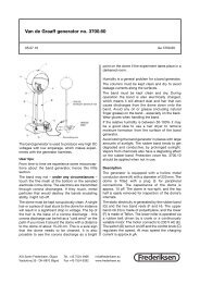
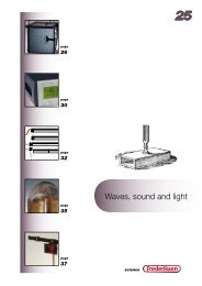
To SF counter<br />
earlier versions via<br />
cable no. 1122.20<br />
To oscilloscope or<br />
measuring instrument<br />
2515.60 Power Supply<br />
On the side: 3.5 mm<br />
connector for 9 VDC<br />
mains adapter<br />
To Science Workshop<br />
interface or sensor input.<br />
Microphone probe rod<br />
no. 2515.50 also<br />
connects here.<br />
A/S Søren <strong>Frederiksen</strong>, Ølgod Tel. +45 7524 4966 info@frederiksen.eu<br />
Viaduktvej 35 · DK-6870 Ølgod Fax +45 7524 6282 www.frederiksen.eu<br />
®
Operation:<br />
When connecting microphones (type 2485.10) to<br />
older counter/timer units (type 2000.XX and<br />
2001.XX), use the DIN connectors marked “Mic 1"<br />
and “Mic 2". The two 5 pole DIN output connectors<br />
can be connected to the DIN connectors on the<br />
counter/timer using cable type 1122.20 (parallel<br />
cable with DIN jacks). NB: Certain older model counter/timers<br />
have only room for 3 pins in the DIN connectors.<br />
In these cases the easiest solution to break<br />
off the two surplus DIN jack pins at each end of the<br />
1122.20 cable.<br />
Microphone 2485.10 to the Pasco interface:<br />
Because of the pin connections on the unit the<br />
mi crophone type 2485.10 can not be connected<br />
directly to the Pasco interface. Instead connect the<br />
microphone to the power supply, and use the<br />
1122.20 parallel cable to connect the microphone<br />
output signal to the Pasco Science Workshop interface.<br />
The parallel cable should be connected in this<br />
case to the DIN connector marked “Sensor” on the<br />
power supply.<br />
Microphone to oscilloscope:<br />
Microphone no 2485.10:<br />
If it is desired that the sound signal from a microphone<br />
be connected to an oscilloscope the type<br />
2485.10 microphone DIN jack is inserted in the DIN<br />
connector marked “Mic 2". Using a shielded cable<br />
with 4 mm safety jacks at one end and a BNC jack in<br />
the other connect the battery box to the oscillo -<br />
scope.<br />
Microphone prope rod no. 2515.50:<br />
The procedure is the same when using microphone<br />
probe rod no. 2515.50, but in this case the microphone<br />
should be connected to the DIN connector<br />
marked “Sensor”.<br />
Sensors:<br />
Many sensors from Pasco and Vernier use 5-pole<br />
DIN jacks and require a 5 VDC supply voltage. For<br />
example: UVA (2872.00), UVB (2872.61), IR (2872.81)<br />
and LUX (2872.51). These should be connected to<br />
the DIN connector marked “Sensor”, and the signal<br />
can be sent to a multimeter or other read out unit<br />
using the 4 mm safety jack connectors.<br />
Spare parts and accessories:<br />
Battery: 9 V block battery. Order no. 3510.10<br />
Net adapter: 9 V. Order no. 3550.10<br />
Parallel cables with DIN jacks: Order no. 1122.20<br />
Shielded cable, banana (4 mm) / BNC:<br />
Order no. 1100.02<br />
®