Untitled
Untitled
Untitled

Create successful ePaper yourself
Turn your PDF publications into a flip-book with our unique Google optimized e-Paper software.
ivisitazione logo aziendale \ Canefantasma Studio, febbraio 2010<br />
GEOPHYSICS INSTRUMENTS<br />
ADVANCED GEOPHYSICS INSTRUMENTS<br />
ADVANCED GEOPHYSICS INS<br />
D GEOPHYSICS INSTRUMENTS<br />
ADVANCED GEOPHYSICS INSTRUMENTS<br />
D GEOPHYSICS INSTRUMENTS<br />
ADVANCED GEOPHYSICS INSTRUMENTS<br />
D GEOPHYSICS INSTRUMENTS<br />
ADVANCED<br />
GEOPHYSICS<br />
INSTRUMENTS<br />
ADVANCE<br />
GEOPHYS<br />
INSTRUM
› Mae 3<br />
CONTENTS<br />
ULTRA SOUNDS<br />
I-SONIC P 11<br />
A5000UM P 12<br />
A3000U P 14<br />
A6000U P 16<br />
SEISMIC EXPLORATIONS<br />
VIBRALOG P 29<br />
A6000S P 30<br />
SYSMATRACK P 32<br />
SEISMIC MONITORING<br />
VIBRAMONITOR P 37<br />
A5000SP P 38<br />
SYSMALOG P 39<br />
SETA SYSTEM P 40<br />
GEO-ELECTRIC EXPLORATIONS<br />
A6000SE P 50<br />
A6000E P 52<br />
MONITORING<br />
DL-8 P 61<br />
DL-8 IP P 62<br />
A5000M-IP P 63<br />
MULTILOG P 64<br />
A5000MA P 65<br />
A5000M P 66<br />
A5000MAW P 68<br />
TERMALOG P 69<br />
A5000T P 70
› Presentazione<br />
4<br />
ADVANCED GEOPHYSICS INSTRUMENTS<br />
ADVANCED GEOPHYSICS INSTRUMENTS<br />
ADVANCED GEOPHYSICS INSTRUMENTS<br />
ADVANCED GEOPHYSICS INSTRUMENTS<br />
ADVANCED<br />
GEOPHYSICS<br />
INSTRUMENTS<br />
ADVANCED<br />
GEOPHYSICS<br />
INSTRUMENTS<br />
Molisana Apparecchiature<br />
Elettroniche Srl (MAE), has<br />
been working in the precision<br />
electronic instrument field<br />
since 1982. MAE is specialized<br />
in the designing, manufacturing<br />
and installation of<br />
electronic instruments and<br />
dedicated software configuration<br />
packages for a wide<br />
variety of inspection applications<br />
and relevant data<br />
processing.<br />
MAE boasts being one of the<br />
first companies worldwide<br />
to develop seismic telematic<br />
networks. Over the years,<br />
it has spread its presence not<br />
only in the domestic market,<br />
but also internationally,<br />
thanks to important cooperation<br />
projects with various<br />
universities and research<br />
centres, both public and private.<br />
The company is currently<br />
involved in some important<br />
research projects<br />
worldwide such as the Seismic-Inclinometric<br />
Network<br />
installed in Quito (Ecuador),<br />
and the 24-bit Digital Telemetry<br />
Seismic Network (S.E.T.A.<br />
Project) in Tbilisi (Georgia),<br />
which are being developed in<br />
cooperation with The National<br />
Institute of Oceanography<br />
and Experimental Geophysics<br />
(OGS) in Trieste (Italy), and<br />
the Georgian National Insti-
› Mae 5<br />
Advanced Geophysics Instruments<br />
tute of Geophysics (IGEM) in<br />
Tbilisi (Georgia).<br />
Besides its main activity in developing<br />
digital seismic networks,<br />
MAE has always been<br />
supporting industry with the<br />
development and manufacture<br />
of precision instrumentation<br />
and equipment<br />
devices for geology and geotechnology,<br />
as well as for<br />
non-destructive inspections<br />
in the engineering and environmental/structural<br />
monitoring<br />
fields.<br />
MAE boasts a wide production<br />
of portable instruments,<br />
as well as fixed working stations<br />
or stations which are<br />
integrated into a particular<br />
area, tailoring instruments<br />
design and manufacturing to<br />
the client’s specific requirements.<br />
MAE innovative solutions<br />
stand out for easeof-use,<br />
high-tech features,<br />
maximum flexibility, modularity<br />
and expandability.<br />
A training support program<br />
featuring training courses<br />
and thematic courses held in<br />
cooperation with various experts<br />
and university scientists,<br />
is constantly updated to<br />
offer in-depth knowledge on<br />
the major geophysical and<br />
geotechnical investigation<br />
techniques.
ULTRA SOUNDS
8<br />
ULTRA SOUNDS<br />
› CONTACT ULTRA-SOUND SURVEYS<br />
(Direct – Indirect – Semi-direct method)<br />
The method is based on the propagation<br />
speed of longitudinal ultra-sonic<br />
waves inside a reinforced concrete<br />
structure. The propagation speeds depends<br />
on the characteristics of the material<br />
such as elasticity, density, presence<br />
of gaps, micro-holes, etc… From<br />
the determination of the following parameters:<br />
reflection, refraction, transit<br />
time (T.O.F.) and mitigation of the vibration<br />
energy, it is possible to obtain information<br />
on:<br />
• Homogeneity of the mix<br />
• Elasto-mechanical characteristics<br />
• Entity, geometry and location of particular<br />
faults or internal defects, variations<br />
in time of the quality parameters<br />
of the concrete<br />
Ultra-sonic tests through which it is<br />
possible to evaluate the transit speed<br />
of the pulses (with known thickness<br />
and time) are particularly important.<br />
The primary goal of the Ultra-sound<br />
survey is to record the time of fly (TOF,<br />
Time of Fly) and the following calculation<br />
of the speed. In order to calculate<br />
the propagation speed of longitudinal<br />
waves (P waves), the arrival of the first<br />
wave-train must be found out with accuracy.<br />
In order to perform this operation<br />
correctly, the instrument must be<br />
equipped with oscilloscope that allows<br />
to visualize the transit wave on the device<br />
display.<br />
The ultra-sound tests can be carried<br />
out with:<br />
• Direct method<br />
When the transmitting and receiving<br />
probes are positioned on the opposite<br />
sides of the element to test.<br />
• Semi-direct method<br />
When the E/R probes are positioned on<br />
adjacent surfaces, usually orthogonal,<br />
of the element to test<br />
• Indirect method<br />
When E/R probes are positioned in the<br />
same side of the structural element to<br />
test.<br />
› CROSS-HOLE ULTRA-SOUND TEST<br />
The cross-hole is a method to analyze<br />
the foundation poles of buildings that,<br />
with the use of ultra-sounds, crosshole,<br />
allow to carry out an accurate<br />
high resolution test. An ultra-sonic<br />
wave is sent from a transmitter to<br />
a receiver, which are convoyed automatically<br />
by the device along the entire<br />
length of the pole inside the pipes<br />
embedded inside of it, during casting.<br />
The speed of the sonic wave and its<br />
energy are strongly influenced by the<br />
quality of the cement. Therefore, it is<br />
possible to assess the characteristics<br />
and give a tomographic representation<br />
in 2D and 3D called diagraphy..
› Mae 9<br />
› SONIC TEST ON MASONRY<br />
The principle of the sonic tests on masonry<br />
is the same as principle of ultrasound<br />
tests on concrete. The only difference<br />
is the method to produce the<br />
longitudinal elastic wave used for the<br />
measurement: a hammer is used instead<br />
of an ultra-sonic pulse. The frequencies<br />
thus produced (a few hundreds<br />
of Hz), lower than those of the<br />
ultra-sounds (a few tens of KHz) are<br />
able to also cross scarcely compact<br />
masonry walls, such as brick-faced<br />
or brick walls, thus allowing to evaluate<br />
the conservation state, through<br />
the speed and/or mitigation values of<br />
the wave produced. This type of test<br />
can also be applied on concrete structures,<br />
which sizes do not allow to use<br />
ultra-sounds, because these can no<br />
longer be measured at a few metres<br />
from the source. The sonic tests give<br />
less accurate values compared to the<br />
tests with ultra-sounds, but they can<br />
be performed also on scarcely compact<br />
materials and/or at a distance of<br />
a few metres.<br />
› PILE INTEGRITY TEST<br />
The sonic echo test is a survey method<br />
consisting in the measurement<br />
of the reflection speed of compression<br />
waves, to assess the integrity of<br />
a pole. The method was conceived in<br />
Holland during the 70s, as instrument<br />
to check the quality of pre-fabricated<br />
foundation poles in concrete, extensively<br />
used in that country. Due to the<br />
regularity of the surfaces of the prefabricated<br />
poles, the sonic echo test<br />
could be used with a high level of reliability.<br />
For this type of test, a compression<br />
wave is propagated until the base<br />
of the pole and is reflected towards its<br />
head. The compression wave is generated<br />
with an impact on the pole head<br />
and the signal recorded by a geophone<br />
is displayed in a graph in real time. If<br />
discontinuities are present in the pole<br />
such as variations of the section or<br />
cracks, these cause reflections. If the<br />
discontinuities are fairly significant,<br />
such as for example a complete fracture<br />
of the concrete, these cause an<br />
almost complete fracture, thus preventing<br />
to detect the base of the pole.<br />
In order to execute the test properly,<br />
the pole head must be accessed. The<br />
geophone is placed on the concrete<br />
surfaced, properly prepared, through<br />
a coupling material and by placing<br />
on top a load of a few kg. When the<br />
head of the pole is hit in a selected<br />
point, the impact enables the acquisition<br />
of the signal produced by the geophone,<br />
which is shown immediately on<br />
the screen. In order to eliminate the<br />
background noise caused from the<br />
construction site activities, the acquisition<br />
can be repeated a few times to<br />
calculate the averages.
› Ultra Sounds<br />
10<br />
SUPPORTED<br />
INVESTIGATION<br />
I-SONIC<br />
A5000UM<br />
A3000U<br />
A6000U<br />
Ultrasonic contact test • • • •<br />
Sonic Inspection on masonry • •<br />
P.I.T. Pile Integrity Test • •<br />
Sonic logging • •<br />
Cross-Hole 2 channel • •<br />
Cross-Hole 3 channel<br />
•
› Mae 11<br />
I-SONIC<br />
SUPPORTED INVESTIGATION<br />
Ultrasonic contact test<br />
Digital instrumentation for ultrasonic<br />
tests through transparency, it can<br />
be used for testing walls, trusses,<br />
partition walls, specimen, laboratory<br />
samples, and other types of concrete<br />
structures or stony materials.<br />
The extremely compact sizes render<br />
I-SONIC suitable for particularly burdensome<br />
uses, where utmost accuracy<br />
in the measurement is required,<br />
together with reliability, sturdiness<br />
and compact sizes. Thanks to the<br />
presence of a large graphic display,<br />
the visualization and interpretation<br />
of the data acquired is easy and immediate.<br />
Each single wave emitted<br />
by the internal generator is visualized<br />
in full and it is also possible to<br />
modify the visualization parameters<br />
to further facilitate the reading of<br />
the crossing speed. The data is saved<br />
on a removable S.D. memory.<br />
The ultrasonic test through contact<br />
is a standardized system in the diagnostics<br />
sector of concrete structures.<br />
From the analysis of the compression<br />
waves P in the material, it is possible<br />
to obtain the transit time (airborne<br />
time T.O.F.), of the ultrasonic waves<br />
in the material and the transmission<br />
speed of the same waves inside the<br />
material tested. The use of this method<br />
at high frequencies is particularly<br />
suitable for compact materials, as<br />
hardened concrete, and on structural<br />
elements of reduced sizes, such as<br />
beams, pillars, etc…<br />
This series of instruments allows to<br />
assess the mechanical characteristics<br />
of the materials, evaluate the<br />
degree of homogeneity and possible<br />
presence of holes, gaps, defects or<br />
building anomalies of the element.<br />
SPECIFICATIONS<br />
Acquisition:<br />
• Signal range: ±2.5<br />
• Time bases: 1μs<br />
• Amplifications: 30dB – 62dB<br />
• Sample resolution: 12 bit<br />
• Samples per event: 320<br />
• Band width: 200kHz<br />
• Filter for ultra-sounds: central frequency<br />
50 kHz<br />
• Channels: 1 TX, 1 RX<br />
• Methods: manual (with button) or<br />
automatic (repetitive in time)<br />
Probes:<br />
• Resonant frequency: 53 kHz<br />
• Diameter: 48mm<br />
• Excitation peak voltage: 500V (normal),<br />
2000V (high)<br />
• Maximum frequency for pulse emission:<br />
1 per second<br />
General data:<br />
• Keyboard: 6 charge-transfer buttons<br />
• Display: mono-chromatic graphic<br />
LCD 320 x 240 pixel<br />
• Measures display: numeric and<br />
graphic<br />
• Power supply: internal batteries AA<br />
type rechargeable and replaceable<br />
(12V – 2.5Ah)<br />
• Typical consumption: 90mA idle,<br />
170mA when taking measurements<br />
• Container: anti-crash, in copolymers<br />
of polypropylene<br />
• Operating temperature: 0-60°C<br />
• Sizes and weight: 23.8 x 6.7 x 14.1<br />
cm, 2.5 Kg<br />
mae-srl.it/go/i-sonic
› Ultra Sounds<br />
12<br />
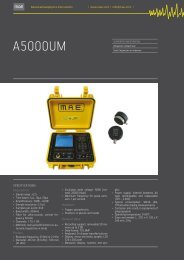
A5000UM<br />
SUPPORTED INVESTIGATION<br />
Ultrasonic contact test<br />
Sonic Inspection on masonry<br />
SPECIFICATIONS<br />
Acquisition:<br />
• Signal range: ±2.5<br />
• Time bases: 1μs, 10μs, 50μs<br />
• Amplifications: 30dB – 62dB<br />
• Sample resolution: 12 bit<br />
• Samples per event: 640<br />
• Band width: 200kHz<br />
• Filter for ultra-sounds: central frequency<br />
50 kHz<br />
• Channels: 1 TX, 1 RX<br />
• Methods: manual (with button) or automatic<br />
(repetitive in time)<br />
Probes:<br />
• Resonant frequency: 53 kHz or 21 Khz<br />
• Diameter: 48 mm (53 kHz) ; 100 mm<br />
(21 kHz)<br />
• Excitation peak voltage: 500V (normal),<br />
2000V (high)<br />
• Maximum frequency for pulse emission:<br />
1 per second<br />
Hammer:<br />
• Trigger: piezoelectric<br />
• Shutters: in plastic and metal<br />
General data:<br />
• Recording support: removable SD memory<br />
up to 2 GB<br />
• Data format: TSV, BMP<br />
• Keyboard: 24 charge-transfer buttons<br />
• Display: mono-chromatic graphic LCD<br />
320 x 240 pixel<br />
• Measures display: numeric and gra-<br />
phic<br />
Power supply: internal batteries AA<br />
•<br />
type rechargeable and replaceable<br />
(12V – 2.5Ah).<br />
• Typical consumption: 90mA idle,<br />
170mA when taking measurements<br />
• Container: anti-crash, in copolymers of<br />
polypropylene<br />
Operating temperature: 0-60°C<br />
•<br />
Sizes and weight: L. 270 x H. 120 x P.<br />
•<br />
246 mm, 3 Kg
› Mae 13<br />
Instrumentation for the execution of<br />
non-invasive surveys of sonic and ultrasonic<br />
type with an electro-mechanical<br />
hammer operating on concrete structures,<br />
masonry and on various types<br />
of building materials on site and in the<br />
laboratory. The extensive spectrum of<br />
incoming frequencies analysed, allows<br />
to take measurements on materials<br />
with different mechanical, compactness<br />
and homogeneity characteristics.<br />
The ultrasonic test through transparency<br />
is a standardized system in the<br />
diagnostics sector of concrete structures.<br />
From the analysis of the compression<br />
waves P in the material, it<br />
is possible to obtain the transit time<br />
(airborne time T.O.F.) of the ultrasonic<br />
waves in the material and the transmission<br />
speed of the same waves inside<br />
the material tested. The use of<br />
this method at high frequencies is<br />
particularly suitable for compact materials,<br />
as hardened concrete and on<br />
structural elements such as trusses,<br />
partition walls, or other types of<br />
concrete structures or stony materials<br />
with good aggregation degree.<br />
The sonic surveys are carried out using<br />
an electro-mechanical hammer<br />
that acts as trigger and a receiving<br />
probe. Waves on the material to inspect<br />
are generated on the trigger<br />
hammer, which are then detected by<br />
the receiving probe and recorded in<br />
the central unit. The sonic method is<br />
extensively used in tests of materials<br />
with scarce propagation characteristics,<br />
non-compact and heterogeneous<br />
materials in which the distances to<br />
travel are fairly high and they cannot<br />
be reached with the ultra-sonic system<br />
at other frequencies. A5000UM<br />
allows to assess the mechanical characteristics<br />
of the materials, evaluate<br />
the degree of homogeneity and possible<br />
presence of holes, gaps, defects<br />
or building anomalies of the element.<br />
Masonry structures, brick-faced walls,<br />
historic and monumental buildings<br />
can be assessed in terms of conservation<br />
state, in a quick and easy manner,<br />
limiting as much as possible the execution<br />
of destructive tests. Thanks to<br />
the presence of a large graphic display,<br />
the visualization and interpretation of<br />
the ultra-sonic waves generated is<br />
easy and immediate, the first reading<br />
can be picked and the speed and quality<br />
values of the material tested can<br />
be read directly on the device display.<br />
Each single wave emitted by the internal<br />
generator is visualized in full and<br />
it is also possible to modify the visualization<br />
parameters to further facilitate<br />
the reading of the crossing speed.<br />
The data is saved on a removable S.D.<br />
memory.<br />
mae-srl.it/go/A5000UM
› Ultra Sounds<br />
14<br />
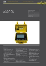
A3000U<br />
SUPPORTED INVESTIGATION<br />
Ultrasonic contact test<br />
Sonic Inspection on masonry<br />
P.I.T. Pile Integrity Test<br />
Sonic logging<br />
Cross-Hole 2 channel<br />
SPECIFICATIONS<br />
Acquisition:<br />
• Measurement range: 100mV – 20V<br />
• Time bases: 20ns – 81.9μs<br />
• Sample resolution: 8 bit<br />
• Samples per event: 8192 for contact<br />
measurements, 640 for log<br />
• Band width: 50 MHz<br />
• Filter for ultra-sounds: central frequency<br />
50 kHz<br />
• Measurement channels: 1<br />
Probes:<br />
• Through contact and sonic test with<br />
hammer: resonant frequency 53 kHz,<br />
diameter 48mm<br />
• From hole: resonant frequency 40 kHz,<br />
diameter 35mm<br />
• Through echo-test: vertical geophone<br />
with resonant frequency 4.5 Hz<br />
• Excitation peak voltage: 500V (normal),<br />
2000V (high)<br />
• Maximum frequency for pulse emission:<br />
1 per second<br />
• Minimum measurement pitch: 10mm<br />
• Motorised reels: no. 2 with 60 metres<br />
of cable<br />
• Encoder position: no. 2, precision 3.6°<br />
• Speed and alignment: managed automatically<br />
Hammer (UM model):<br />
• Trigger: piezoelectric<br />
• Shutters: in plastic and metal<br />
General data:<br />
• Power supply: 12V DC, supplied by a<br />
specific power box with 24Ah batteries<br />
• Average absorption: 1.5A (standby) –<br />
2.5A (while taking measurements)<br />
• Interfaces available: LAN, USB, VGA<br />
• Display: LCD 7” with touch-screen<br />
• Operative System: Windows Embedded<br />
Standard 2009<br />
• Data format: WAV, ASCII, DCS (owned)<br />
• Environmental operating conditions:<br />
-20/80 °C<br />
• Sizes: 28 x 24.6 x 17 cm<br />
• Weight of the central unit: 5kg
› Mae 15<br />
A3000U device is a complete system<br />
for non-destructive structural<br />
inspections through ultra-sounds on<br />
poles, deep foundations, infrastructural<br />
works or buildings. The system<br />
consists of a computerised central<br />
unit of extremely compact sizes,<br />
to which it is possible to connect, according<br />
to the type of survey, transducers<br />
for surveys in direct contact or<br />
motorised reels controlled electronically,<br />
on which probes are assembled<br />
with drilling power, for cross-holes<br />
surveys. The central unit integrates<br />
the ultra-sound generator, 2 acquisition<br />
channels, the control electronics<br />
for the automatic management of<br />
the probes when being raised/lowered<br />
in the probing tubes in the cross-hole<br />
test and for saving the data on internal<br />
or external memory of USB type.<br />
Thanks to the user-friendly management<br />
software, all the functions are<br />
selected through menus that can be<br />
browsed simply, by touching the large<br />
transflective 6.4” touch screen LCD<br />
monitor. In CROSS-HOLE surveys on<br />
concrete poles, in order to obtain the<br />
proper measurement of the crossing<br />
delay of the wave and for the optimal<br />
receipt of the signal, the probes must<br />
be perfectly aligned when taking the<br />
measurement. Thanks to the management<br />
through micro-processor,<br />
A3000U is able to ensure the constant<br />
alignment between probes when taking<br />
the measurement, and in case the<br />
alignment is not achieved, it compensates<br />
the speed between the same<br />
probes. The device carries out an ongoing<br />
testing cycle of the alignment<br />
of the probes when being lowered and<br />
raised inside the holes. This procedure<br />
allows to obtain the maximum resolution<br />
during the acquisition phase.<br />
The data acquired at each single pulse<br />
is displayed in real time on the large<br />
colour monitor, allowing an immediate<br />
visualization of possible imperfections<br />
in the structure inspected.<br />
The procedure to carry out cross-hole<br />
surveys with 2 channels is managed<br />
by A3000U central unit in automatic<br />
mode. The only operations required<br />
to the operator consist in positioning<br />
the encoders for reading the position<br />
of the motorised probes on the tubes<br />
envisaged for probing and to initially<br />
align the probes on the pole head. At<br />
this point, the data acquisition is enabled<br />
by pressing a button, it is managed<br />
in automatic mode by the central<br />
unit, and the data can be checked<br />
as soon as it is acquired. Once the test<br />
is concluded, it is possible to print immediately<br />
the test report containing<br />
the data of the probing directly in the<br />
construction site. Using the contact<br />
transducers (supplied), it is possible<br />
to use the equipment in transparency<br />
tests of walls, trusses, partition walls<br />
or other infrastructural works that require<br />
direct surveys or as laboratory<br />
analyser to check specimen, concrete<br />
samples, rock, stony or plastic materials.<br />
With the direct analysis method, it<br />
is possible to fully analyze each wave<br />
generated. The instrument can be integrated<br />
with:<br />
- expansion Kit for sonic test on walls<br />
with electro-mechanical hammer<br />
- expansion Kit for I.T. TEST (eco-ranging<br />
test) on foundation poles<br />
- expansion Kit for sonic logging on<br />
foundation poles<br />
mae-srl.it/go/A3000U
› Ultra Sounds<br />
16<br />
A6000U<br />
SUPPORTED INVESTIGATION<br />
Ultrasonic contact test<br />
P.I.T. Pile Integrity Test<br />
Sonic logging<br />
Cross-Hole 2 channel<br />
Cross-Hole 3 channel<br />
SPECIFICATIONS<br />
Acquisition:<br />
• Measurement range: 100mV – 20V<br />
• Time bases: 20ns – 81,9μs<br />
• Sample resolution: 8 bit<br />
• Samples per event: 8192 for contact<br />
measurements, 640 for log<br />
• Band width: 50 MHz<br />
• Filter for ultra-sounds: central frequency<br />
50 kHz<br />
• Measurement channels: 2<br />
Probes:<br />
• Through contact: resonant frequency<br />
53 kHz, diameter 48mm<br />
• From hole: resonant frequency 40<br />
kHz, diameter 35mm<br />
• Through echo-test: vertical geophone<br />
with resonant frequency 4.5 Hz<br />
• Excitation peak voltage: 500V (normal),<br />
2000V (high)<br />
• Maximum frequency for pulse emission:<br />
1 per second<br />
• Minimum measurement pitch: 10mm<br />
• Motorised reels: no. 3 with 60 metres<br />
of cable<br />
• Encoder position: no. 3, precision<br />
3.6°<br />
• Speed and alignment: managed automatically<br />
General data:<br />
• Power supply: 12V DC, supplied by a<br />
specific power box with 36Ah batteries<br />
• Average absorption: 2A (standby) - 3A<br />
(while taking measurements)<br />
• Interfaces available: LAN, USB, VGA<br />
• Display: LCD 10.4” with touch-screen,<br />
optical bonding<br />
• Operative System: Windows Embedded<br />
Standard 2009<br />
• Data format: WAV, ASCII, DCS (owned)<br />
• Environmental operating conditions:<br />
-20/80 °C<br />
• Sizes: L470 x H229 x P351 mm<br />
• Weight of the central unit: 5 kg
› Mae 17<br />
A6000U device represents the most<br />
complete and advanced solution for<br />
non-destructive structural surveys<br />
through ultra-sounds on deep foundations,<br />
infrastructural works or buildings.<br />
The system consists of a computerised<br />
central unit of compact sizes,<br />
to which it is possible to connect, according<br />
to the type of survey, transducers<br />
for surveys in direct contact or<br />
motorised reels controlled electronically,<br />
on which probes are assembled<br />
with high drilling power, for cross-holes<br />
surveys on foundation poles. The central<br />
unit integrates the ultra-sound<br />
generator equipped with 3 channels<br />
with two power levels and the control<br />
electronics for the automatic management<br />
of the probes when being<br />
raised/lowered (cross-hole) and for<br />
saving the data on internal or external<br />
memory of USB type. Thanks to the<br />
user-friendly management software,<br />
all the functions are selected through<br />
menus that can be browsed simply, by<br />
touching the large transflective 10.4”<br />
touch screen LCD monitor. Using the<br />
contact transducers (supplied), it is<br />
possible to use the equipment to test<br />
walls, trusses, partition walls or other<br />
infrastructural works that require direct<br />
surveys or as laboratory analyser<br />
to check specimen, laboratory samples,<br />
rock, stony or plastic materials.<br />
Thanks to the presence of the colourdisplay,<br />
the visualization and interpretation<br />
of the data acquired is easy<br />
and immediate. In the direct analysis<br />
mode, each wave emitted by the internal<br />
generator is visualized in full, and<br />
it is also possible to modify the visualization<br />
parameters to further facilitate<br />
the reading of the crossing speed<br />
and possible presence of defects in<br />
the material inspected. With the use<br />
of 3 probes with simultaneous automatic<br />
operation, A6000U device allows<br />
to save 1/3 of the time needed<br />
for probing, since three relative sections<br />
can be obtained with one single<br />
rising/lowering operation of the<br />
probes in the pole to test (which must<br />
be tested with 3 tubes). The system<br />
carries out an ongoing testing cycle<br />
of the alignment of the probes when<br />
being lowered and raised inside the<br />
holes. The data acquired at each single<br />
pulse is displayed in real time on<br />
the large monitor, allowing an immediate<br />
visualization of possible imperfections<br />
in the structure inspected. The<br />
procedure to carry out cross-hole surveys<br />
with 2 or 3 channels is managed<br />
by A6000/U central unit in automatic<br />
mode. The only operations required<br />
to the operator consist in positioning<br />
the encoders for reading the position<br />
of the motorised probes on the tubes<br />
envisaged for probing and to initially<br />
align the probes on the pole head.<br />
Once this operation has been completed,<br />
the data is acquired by pressing<br />
a button and managed in automatic<br />
mode by the central unit. It is<br />
possible to check the data when acquired,<br />
so as to assess the trend of the<br />
test in real time. It is possible to print<br />
immediately the test reports containing<br />
the data of the probing just carried<br />
out in the construction site.<br />
mae-srl.it/go/A6000U
› Ultra Sounds<br />
18<br />
ACCESORIES<br />
I-SONIC<br />
A5000UM<br />
A3000U<br />
A6000U<br />
Sonic Logging • •<br />
Sonic Inspection On Masonry • •<br />
P.I.T. Pile Integrity Test • •<br />
Borehole Probe • •<br />
Contact Probe • • • •<br />
Usb Printer • •<br />
Cross-Hole manuale 2/3 canali • •<br />
Adattatori tronco-conici sonde ultrasuoni • • • •<br />
Sonsa ultrasuoni 21 Khz • • • •<br />
SOFTWARE<br />
WIN-SONIC<br />
DG-WIN<br />
ECHO-WIN<br />
Contact measures test report<br />
•<br />
Sonic Inspection on masonry test report<br />
•<br />
P.I.T. Pile Integrity Test test report<br />
•<br />
Sonic logging test report<br />
•<br />
2 channels Cross-Hole test report •<br />
3 channels Cross-Hole test report •
› Mae 19<br />
ACCESSORIES<br />
› SONIC TESTS ON MASONRY STRUCTURES<br />
Complete kit for inspections on materials that present low propagation characteristics, non-compact<br />
and and also when it is necessary to cover long distances which would be out of reach for a<br />
high frequency ultrasonic system includes:<br />
• Hammer with integrated trigger • Receiver probe • Software Win-Sonice<br />
› I.T. TEST - ECHOMETRIC TEST ON FOUNDATION PILES<br />
Complete kit for non-destructive tests, assessing the structural integrity of deep foundations<br />
and infrastructural works by applying the Echometric Test (IT) inspection method. Includes:<br />
• Hammer • Seismic receiver 4,5 Hz • Software Echo-Win<br />
› CROSS-HOLE 2/3 CHANNELS<br />
Complete kit for Cross-hole Test on foundations piles with manual modality of investigation<br />
Includes:<br />
• 2/3 channels encoder in aluminum transport case<br />
• Encoder aluminum tripod in soft case<br />
• 2/3 Cross-Hole ultrasonic probes with 60 mt cable and cable spool<br />
› SONIC LOGGING MOTORIZED PROBE<br />
Sonda combinata TX/RX con bobina motorizzata per indagini Cross-Hole su pali di fondazione strumentati<br />
con unico tubo di sondaggio.<br />
› PROBE FOR SONIC LOGGING (CROSS-HOLE)<br />
Resonant frequency: 40 KHz<br />
Safety seal attachment<br />
Watertight: 150 m<br />
Stainless steel case<br />
Length: 120 mm - Diameter: 32 mm<br />
› CONTACT TYPE ULTRASONIC PROBE<br />
Contact type ultrasonic transmitter probe for sonic investigation on masonry, frequency of<br />
resonance 21 Khz.<br />
› CONIC ADAPTER FOR CONTACT ULTRASONIC PROBE<br />
Conic adapter for contact ultrasonic probes for investigations on wood.<br />
› SONDA ULTRASUONI 21 KHZ<br />
Sonda ultrasuoni frequenza 21 Khz.
› Ultra Sounds<br />
20<br />
SOFTWARE<br />
› DG-WIN<br />
DGWIN is an application for display and detailed analysis of logs performed<br />
with M.A.E. equipment for CROSS-HOLE surveys on deep foundations.<br />
Description of main functions:<br />
Exports graphic<br />
Enables graphics to be exported in bitmap format<br />
Exports times<br />
Activates the function of exporting arrival times in a text file<br />
Copies graphic<br />
Copies the graphic currently displayed in the Windows notes<br />
Data<br />
Allows modification or integration of additional information saved along<br />
with the log at the time of its creation. The information displayed is<br />
used to make up the print form and is an important addition to the<br />
graphic.<br />
mae-srl.it/go/dgwin<br />
Log<br />
Displays the last log loaded. If the trace is not completely visible you<br />
can scroll it vertically and/or horizontally<br />
Displays individual wave<br />
Displays the detail of the signals comprising the log.
› Mae 21<br />
› WIN-SONIC<br />
The ultrasound survey on contact is a standardized system in the concrete<br />
structure diagnostics sector, making use of a transmitter probe<br />
and a receiver: through an analysis of the compression (P) waves in the<br />
material, the transit time (T.O.F. time of flight) is obtained for the ultrasound<br />
waves in the material, the distance is noted and the transmission<br />
speed is displayed. This method, at high frequencies, is therefore<br />
specifically used for compact materials such as hardened concrete or<br />
small-size structural elements like beams, pillars, etc.<br />
WIN SONIC reporting software allows the display and in-depth analysis<br />
of individual wave forms acquired, with the aim of creating a customized<br />
report of the measurements carried out.<br />
A comparison of several wave forms can also be carried out simultaneously.<br />
The software is suitable for reporting data of surveys carried out with<br />
ultrasounds in contact or sonic tests on masonry.<br />
mae-srl.it/go/win-sonic<br />
› ECHO-WIN<br />
EchoWin is a simple-to-use program, supplied as an accessory to M.A.E.<br />
equipment for echometric measurement.<br />
It enables the display of acquisitions carried out on site and the printing<br />
of customized reports for individual tests.<br />
Main characteristics:<br />
- possibility of editing the resulting curve, through the inclusion or exclusion<br />
of individual reflectograms;<br />
- possibility of refining detection of the main echo through a graphic<br />
cursor;<br />
- modification of the crossing speed and recalculation of the depths<br />
corresponding to the echoes detected;<br />
- addition of operator observations and insertion of further reference<br />
frameworks;<br />
- comparison through multiple windows between tests on structures<br />
with comparable characteristics;<br />
- customization of logo headings on printed reports.<br />
mae-srl.it/go/echo-win
SEISMIC<br />
EXPLORATIONS
24<br />
SEISMIC<br />
EXPLORATIONS<br />
› SEISMIC EXPLORATION OF REFRACTION TYPE<br />
The seismic exploration of refraction<br />
type is among the most diffused and<br />
used active seismic methods. This<br />
type of survey has the purpose to determine<br />
the thickness of the overburdens<br />
(aerated) above a rigid sub-layer<br />
and reconstruct a seismic stratigraphic<br />
sequence in terms of apparent longitudinal<br />
speed. If carried out according<br />
to more sophisticated calculation<br />
methods, it can be used to intercept,<br />
measure and characterize geo-structural<br />
profiles. Seismic exploration of<br />
refraction type is carried out by placing<br />
equidistant geophones in line on<br />
the ground, and generating seismic<br />
pulses through mechanical “inputs”.<br />
Then the travelling times of the pulses<br />
that once penetrated in the ground<br />
are refracted nearby the lithological<br />
passages at different density, will be<br />
measured.<br />
› SEISMIC EXPLORATION OF REFLECTION TYPE<br />
The seismic exploration of reflection<br />
type, which is extensively used in oil<br />
explorations, is also used nowadays<br />
to obtain detailed information on surface<br />
soils. Due to the high resolution<br />
of the survey, it is used to define the<br />
development of geological structures<br />
in the sub-soil, defining the shapes,<br />
sizes and positions. The prospecting<br />
is carried out by placing high frequency<br />
geophones in line and close to each<br />
other, sending seismic pulses through<br />
energy (also at high frequency) and<br />
by measuring the travelling times of<br />
the waves that, once penetrated in<br />
the ground, are reflected by the uneven<br />
surfaces that delimit the lithological<br />
passages with net impedance<br />
contrast.
› Mae 25<br />
› TOMOGRAPHIC SEISMIC EXPLORATION<br />
This survey method is used to identify<br />
physical-geometrical anomalies of the<br />
sub-soil with a definitely higher resolution<br />
compared to the other seismic<br />
exploring methods, giving the opportunity<br />
to create an image of the subsoil<br />
containing all the anomalies, even<br />
the most complex ones, which cannot<br />
be resolved with other methods.<br />
In particular, the tomographic method<br />
allows to reconstruct the geometric<br />
distribution of the elements that<br />
constitute a specific section, starting<br />
from the analysis of the behaviour of<br />
the radiations that cross it.<br />
› DOWN-HOLE SEISMIC EXPLORING<br />
This type of survey is performed for<br />
the mechanical characterisations of<br />
grounds crossed during the probing<br />
phase. The technique consists<br />
in the measurement of the travelling<br />
times of the elastic waves between<br />
the seismic source on the<br />
surface and the geophones located<br />
inside the probing hole, properly conditioned<br />
with PVC pipe or geo-technical<br />
pipe. The seismic exploring activity<br />
in the down-hole takes place by<br />
placing one or more triplets of sensors<br />
(horizontal and vertical) inside<br />
one of the probing holes and at various<br />
depths, aimed at receiving the<br />
seismic signals generated through<br />
ram on anchored plate. Energy will<br />
be supplied in phase inversion in order<br />
to polarise phases S on a horizontal<br />
plane H, according to an orientation<br />
of 180°. Through seismic speeds<br />
Vp and Vs, it is possible to obtain information,<br />
such as elastic modules<br />
and geo-seismic parameters. Vs 30<br />
can be measured on probing holes<br />
up to 30 metres of depth (O.P.C.M<br />
3274/2003).<br />
› CROSS-HOLE SEISMIC EXPLORING<br />
This type of survey is performed<br />
through the physical –dynamic characterisation<br />
of the portion of ground<br />
between the two probing holes. The<br />
technique consists in the measurement<br />
of the travelling times of the elastic<br />
waves between the source located<br />
in a hole and the geophone/s located<br />
in another hole/s at the same depth.<br />
The cross-hole is made by introducing<br />
the borehole in one of the holes<br />
and the tridimensional geophone (or<br />
geophones) in another hole/s aimed at<br />
receiving the seismic signal incoming<br />
from the source at the same level. The<br />
elastic modules and mitigations of the<br />
medium between the holes can be obtained<br />
from this test.
› Seismic Explorations<br />
26<br />
› M.A.S.W. (Multichannel Analysis of Surface Waves)<br />
The MASW (Multichannel Analysis of<br />
Surface Waves) technique has the objective<br />
to identify variation profiles<br />
with the depth of the speeds of volume<br />
waves (Vp and Vs). The method<br />
is based on the known relations between<br />
these speeds and the dispersion<br />
of surface (or Rayleigh) waves<br />
observed when propagating through<br />
a stratified elastic medium. The analysis<br />
can be based on signals produced<br />
with a borehole on site by acquisition<br />
device (with a ram or explosion), or on<br />
the recording of the vibrations produced<br />
by far away sources (rives, industrial<br />
activities, traffic, etc).<br />
In the first case, we are talking about<br />
active MASW, with which it is possible<br />
to explore a few tens of metres of<br />
sub-soil, and in the second case, we<br />
are talking about passive MASW, that<br />
allows to reach greater depths, in particular<br />
conditions.<br />
Passive MA.S.W. is used with the purpose<br />
to obtain a speed profile 1D of<br />
the elastic waves of cut S. The technique<br />
consists in the recording of the<br />
“seismic noise” in temporal windows<br />
and following study of the signal<br />
processed. It is carried out by arranging<br />
a bidimensional geophonic chain<br />
with low resonant frequency in line<br />
or in “array” (circular and irregular geometries)<br />
and measuring the environmental<br />
noise. From the F-K analysis<br />
(frequency-space) of the wave-trains,<br />
it is possible to obtain a dispersion<br />
curve of surface waves that leads<br />
to the calculation of the speed profile<br />
of the shear waves and estimate<br />
of a coverage in relation to the semispace.<br />
› S.A.S.W. (Spectral Analysis of Surface Waves)<br />
The Spectral analysis of Surface Waves<br />
SASW allows to determine the speed<br />
profile of the shear waves of a particular<br />
ground. The method is based on<br />
the use of the dispersive properties<br />
of surface waves (Rayleigh) generated<br />
by a surface impulsive input. The<br />
depths explored vary from a few centimetres<br />
(road floors) to a few tens of<br />
metres. SASW is carried out by placing<br />
2 geophones in line, in the ground,<br />
with oscillation frequency from 14<br />
to 1 Hz, and registering the seismograms.<br />
The speeds profile of waves Vs<br />
is obtained from studying the phase<br />
speeds of Rayleigh waves. The data<br />
elaboration consists in determining<br />
the Coherence function, the Cross<br />
Power Spectrum phase and the construction<br />
of the dispersion curves<br />
of the Speed during the experimental<br />
phase in depth. In conclusion, the<br />
propagation phenomenon of the surface<br />
waves is simulated with the purpose<br />
to identify the rigidity profile<br />
reproduced by the experimental dispersion<br />
curve.
› Mae 27<br />
› PASSIVE SEISMIC – EXPLORATION FOR THE EVALUATION OF THE<br />
LOCAL SEISMIC RESPONSE – MICRO EARTHQUAKES<br />
This technique is used to obtain information<br />
concerning possible dynamic from the convolution of the frequen-<br />
the study of the spectrums obtained<br />
amplification effects of seismic waves cy of the signal recorded in the domain<br />
for the three components of the<br />
in “ emersion ”. It is based on the recording<br />
of the background noise in ground motion and the application<br />
the time domain and following elaboration<br />
of the signal’s frequencies in (H/V), allows to define and measure<br />
of techniques on spectrum analysis<br />
the domain. It is carried out by placing<br />
a tridimensional geophone on the and the seismic frequency of the<br />
possible local seismic amplifications<br />
ground with low frequency response site. The measurements of the microearthquake<br />
can also be taken in linear<br />
and by recording the seismic noise in<br />
different temporal windows. Later on, “arrays” for the localization of faults.<br />
› NAKAMURA METHOD<br />
A significant part of the damages observed<br />
in destructive earthquakes all<br />
over the world is associated with the<br />
amplification of seismic waves due to<br />
the effects of the local site. The analysis<br />
of the site response is therefore essential<br />
in the evaluation of the seismic<br />
risk in areas subject to earthquakes.<br />
In order to evaluate the effects of the<br />
local site, a series of surveys must be<br />
carried out. Among the empiric methods,<br />
the method of spectrum analyses<br />
H/V on environmental vibrations is<br />
one of the most common. The method,<br />
also called “Nakamura” technique<br />
(Nakamura, 1989), was introduced by<br />
Nogoshi and Igarashi (1971) based on<br />
the initial studies of Kanai and Tanaka<br />
(1961). Since then, many researchers<br />
worldwide performed a large number<br />
of applications.<br />
An important requirement to carry out<br />
the H/ V method consists in a fairly good<br />
knowledge of seismology combined<br />
with basic information on local geological<br />
conditions supported by geo-physical<br />
and geo-technical data. The method<br />
is generally applied in micro-zoning<br />
studies and in the analysis of the local<br />
response of specific sites.<br />
› SEISMIC MONITORING<br />
Seismic monitoring is carried out in areas<br />
subject to risks related to a seismogenic<br />
activity, by acquiring the<br />
seisms with time and recording the<br />
seismograms. Seismic stations are<br />
used able to record in threshold or<br />
continuous type, and low frequency<br />
geophones or seismic accelerometers.<br />
The recording in the long period,<br />
of the earthquakes relative to a<br />
site or fairly large area allows to configure<br />
the seismic scenario of an area<br />
and evaluate the risk and vulnerability<br />
conditions. If the monitoring activity<br />
is supported by specific knowledge<br />
of geological and geo-technical<br />
type, we are talking about seismic Micro-zoning.
› Seismic Explorations<br />
28<br />
SUPPORTED<br />
INVESTIGATION<br />
VIBRALOG<br />
A6000S<br />
SYSMATRACK<br />
Seismic refraction investigation • •<br />
Seismic riflession investigation • •<br />
Seismic tomography<br />
•<br />
Down-hole / Cross-hole • •<br />
M.A.S.W. / S.A.S.W. / Re.Mi. • •<br />
Passive seismic acquisition • •<br />
Seismic vibration monitoring • •<br />
Nakamura method • •
› Mae 29<br />
VIBRALOG<br />
SUPPORTED INVESTIGATION<br />
Passive seismic acquisition<br />
Seismic vibration monitoring<br />
Nakamura method<br />
mae-srl.it/go/vibralog<br />
24 bit seismograph for passive seismic<br />
activity, particularly indicated<br />
for recording micro-earthquakes or<br />
seismic vibrations. The data acquisition<br />
methods (timed or with trigger<br />
threshold) are set through the software<br />
easily and quickly. Equipped<br />
with graphic display, keyboard, memory<br />
support of Secure Digital (S.D.)<br />
type and internal battery, seismograph<br />
VIBRALOG is particularly easy<br />
to use also in less favourable environments<br />
and conditions.<br />
Thanks to the MAE data acquisition<br />
and conversion card, based on one<br />
single A/D signal converter for each<br />
inlet channel (SST technology), it allows<br />
to obtain the best possible resolution<br />
when acquiring the data for<br />
each single inlet channel and it allows<br />
to record and graphically visualize<br />
up to 4 channels coming from<br />
seismic sensors (with single component<br />
or tridimensional).<br />
Thanks to its dynamic characteristics,<br />
the instrument is particularly<br />
suitable to determine the resonance<br />
frequency of the site, through<br />
the H/V ratio method and to acquire<br />
transitional events (caused by natural<br />
seismicity or human activities)<br />
with the purpose to calculate the<br />
maximum speeds of the stresses suffered<br />
by a structure.<br />
SPECIFICATIONS<br />
• Converters: 24 bit resolution, sigma- delta<br />
technology<br />
• Dynamic range: 144 dB (theoretical)<br />
• Maximum distortion: +/-0.0010%<br />
• Band width: 2Hz-30KHz<br />
• Common mode rejection: 110dB at 60Hz<br />
• Diaphony: -120dB at 20Hz<br />
• Noise threshold of the programmable amplifier:<br />
27nV<br />
• Maximum range of inlet signal: +/-5V<br />
• Inlet impedance at 1000 samples/second:<br />
20MΩ<br />
• Amplification levels: 0dB, 6dB, 12dB, 18dB,<br />
24dB, 30dB, 36dB that can be set singularly<br />
for each channel<br />
• Anti-alias filter: -3dB, 80% of Nyquist frequency,<br />
-80dB<br />
• Pre-trigger time: from 1% to 50% of the event<br />
duration<br />
• Sampling frequencies 100, 500, 1000, 2000<br />
samples per second; 250c/s in continuous recording<br />
• Sampling intervals: 0.5, 1.0, 2.0, 4.0, 10.0 ms<br />
• Length of the event recorded: from 512 to<br />
21504 samples (215sec. at 100c/s or 10.7sec.<br />
at 2000c/s). Depending on SD capacity in continuous<br />
recording<br />
• Delay: not available<br />
• Channels: 3 + 1 optional. Possibility to use<br />
from 1 to the maximum number of channels<br />
installed for each acquisition<br />
• Test on instruments: only in the laboratory.<br />
Internal self-calibration of the converters prior<br />
to each acquisition<br />
• Digital filters: selected automatically based<br />
on the sampling frequency<br />
• Data storage: on removable SD memory, up<br />
to 2 GB<br />
• Trigger: 10 threshold levels for each channel<br />
(minimum 8mV – max. 5V). Up to 3 coincidence<br />
combinations between channels<br />
• Data format: SEG-2 standard (32-bit long integer),<br />
BIN convertible in ASCII<br />
• Power supply: 12V DC. Internal batteries of<br />
2.5Ah. Average absorption: 150mA.<br />
• Environmental conditions: -20/80°C<br />
• Display: mono-chromatic graphic LCD 320 x<br />
240 pixel<br />
• Keyboard: 6 charge-transfer buttons<br />
• Sizes: 23.8 x 6.7 x 14.1 cm<br />
• Weight: 1.4 Kg (cables and sensors excluded)
› Seismic Explorations<br />
30<br />
A6000S<br />
SUPPORTED INVESTIGATION<br />
Seismic refraction investigation<br />
Seismic riflession investigation<br />
Seismic tomography<br />
Down-hole / Cross-hole<br />
M.A.S.W. / S.A.S.W. / Re.Mi.<br />
Passive seismic acquisition<br />
Seismic vibration monitoring<br />
Nakamura method<br />
SPECIFICATIONS<br />
• Converters: 24 bit resolution, sigma-delta<br />
technology<br />
Dynamic range: 144 dB (theoretical)<br />
•<br />
Maximum distortion: +/-0.0010%<br />
•<br />
Band width: 2Hz-30KHz<br />
•<br />
Common mode rejection: 110 dB at 60 Hz<br />
•<br />
Diaphony: -120dB at 20 Hz<br />
•<br />
Noise threshold of the programmable am-<br />
•<br />
plifier 27nV<br />
• Trigger precision: 1/30 of the sampling time<br />
• Maximum range of inlet signal: +/-5V<br />
• Inlet impedance at 1000 samples/second:<br />
20Mohm<br />
• Amplification levels: 0 dB, 6 dB, 12 dB, 18 dB,<br />
24 dB, 30 dB, 36 dB that can be set singularly<br />
for each channel or for groups of channels<br />
that can be organized freely<br />
• Anti-alias filter: -3dB, 80% of Nyquist frequency,<br />
-80dB<br />
• Pre-trigger time: 1, 2, 3, 4, 5, 6, 7, 8, 9, 10, 11,<br />
12, 13, 14, 15, 16, 17, 18, 19, 20, 50, 100, 200,<br />
300, 400, 500ms<br />
• Sampling intervals: 1/30, 1/15, 1/7.5, 1/3.75,<br />
0.5, 1.0, 2.0, 10.0, 20.0 ms<br />
• Number of samples per event: set from 1024<br />
to 43520 with increases of 512<br />
• Interfaces available: LAN, USB, VGA<br />
• Channels: configurations of 12, 24 or 36<br />
channels. Possibility to use from 1 to the<br />
maximum number of channels installed for<br />
each acquisition<br />
• Test on instruments: only in the laboratory<br />
• Internal self-calibration of the converters<br />
prior to each acquisition<br />
• Digital filters: selected automatically based<br />
on the sampling frequency<br />
• Geophone tests: automatic check to identify<br />
interruptions of cables or broken geophones<br />
or in short circuit. Real time visualization of<br />
the signals coming from the geophones<br />
• Data storage: inside an internal FLASH memory<br />
(up to 3GB available) and/or on removable<br />
pen-drive USB<br />
Trigger: positive, negative (optional with<br />
•<br />
contact lock) with threshold regulated<br />
through a software<br />
• Data format: SEG-2 standard (32-bit long integer)<br />
or ASCII<br />
• Power supply: 12V DC, supplied by a specific<br />
re-chargeable power box. Average absorption:<br />
1.5A<br />
• Display: LCD 10.4” with touch-screen, optical<br />
bonding<br />
• Sizes and weight: 40.4x17.4x33 cm, 5 Kg (cables<br />
and sensors excluded)<br />
• Environmental conditions: -20/80°C<br />
• Operative System: Windows Embedded<br />
Standard 2009<br />
• Display optical bounding
› Mae 31<br />
MAE A6000S 24-bit seismograph for<br />
seismic prospecting stands out for its<br />
data acquisition platform of last generation<br />
combined to the user-friendly<br />
operative system structured in menus<br />
that can be browsed, with different<br />
functions according to the type<br />
of seismic probing selected by simply<br />
touching the colour, touch-screen<br />
monitor of large sizes.<br />
The main characteristic of this series<br />
of seismographs is the 24-bit<br />
resolution for each single channel.<br />
This result is achieved thanks to the<br />
adoption of a new, 24 bit, MAE data<br />
acquisition card that uses an A/D digital<br />
converter for each inlet channel<br />
of the seismograph (SST technology).<br />
The adoption of this architecture<br />
renders A6000S ideal for all types of<br />
active and passive seismic prospecting,<br />
and for structural surveys and inspections<br />
on buildings and infrastructural<br />
works (acquisition of vibrations<br />
with accelerometers or low frequency<br />
seismic sensors, tomographic surveys,<br />
etc).<br />
Thanks to the great versatility and<br />
numerous automatic, pre-acquisition<br />
checking procedures, from the proper<br />
connection of the geophones to the<br />
analysis of the noise relative to the<br />
site inspected, the data acquisition<br />
is always particularly easy to handle<br />
by anybody. It is also possible to carry<br />
out a first analysis of the data acquired,<br />
also for single wave, directly<br />
on site, visualizing the seismograms<br />
in details, with just a few simple operations.<br />
The data is saved on an internal,<br />
solid state hard disk, for better<br />
protection in case of collisions, or<br />
on an external USB memory.<br />
mae-srl.it/go/A6000S
› Seismic Explorations<br />
32<br />
SYSMATRACK<br />
SUPPORTED INVESTIGATION<br />
Seismic refraction investigation<br />
Seismic riflession investigation<br />
Down-hole / Cross-hole<br />
M.A.S.W. / S.A.S.W. / Re.Mi.<br />
24 bit seismograph for seismic prospecting<br />
with refraction, reflection survey,<br />
active and passive MASW (Re.Mi.),<br />
SASW, Down-hole, Cross-hole methods.<br />
The unit is equipped with acquisition<br />
card with 24 bit resolution and<br />
is available in the 12-channel version<br />
that can be extended to 24. Two 24-<br />
pole connectors for the seismic cables<br />
of 12 channels each, the connector for<br />
the starter, the external 12 V supply<br />
and the USB interface to connect the<br />
notebook or PC for the management<br />
of the instrumentation (not supplied)<br />
are located on the front panel. All parameters<br />
relative to the type of seismic<br />
survey that is carried out easily<br />
and quickly, are set up through the<br />
Sysmatrack Manager software, that<br />
can be installed on any PC or notebook<br />
connected to the acquisition unit.<br />
SPECIFICATIONS<br />
• Converters: 24 bit resolution, sigma- delta<br />
technology<br />
• Dynamic range: 144 dB (theoretical)<br />
• Maximum distortion: +/-0.0010%<br />
• Band width: 2Hz-30KHz<br />
• Common mode rejection:<br />
• Diaphony: -120dB at 20 Hz<br />
• Noise threshold of the programmable amplifier<br />
27nV<br />
• Trigger precision: 1/30 of the sampling time<br />
• Maximum range of inlet signal: +/-5V<br />
• Inlet impedance at 1000 samples/second:<br />
20Mohm<br />
• Amplification levels: 0 dB, 6 dB, 12 dB, 18 dB,<br />
24 dB, 30 dB, 36 dB that can be set singularly<br />
for each channel or for groups of channels<br />
that can be organized freely<br />
• Anti-alias filter: -3dB, 80% of Nyquist frequency,<br />
-80dB<br />
• Pre-trigger time: 1, 2, 3, 4, 5, 6, 7, 8, 9, 10, 11,<br />
12, 13, 14, 15, 16, 17, 18, 19, 20, 50, 100, 200,<br />
300, 400, 500ms<br />
• Sampling intervals: 1/15, 1/7.5, 1/3.75, 0.5,<br />
1.0, 2.0, 10.0, 20.0 ms<br />
• Number of samples per event: set from 1024<br />
to 43520 with increases of 512<br />
• Delay: not available<br />
• Interfaces available: USB (it requires a control<br />
PC)<br />
• Channels: configurations of 12, 24 channels.<br />
Possibility to use from 1 to the maximum<br />
number of channels installed for each<br />
acquisition<br />
• Test on instruments: only in the laboratory<br />
• Internal self-calibration of the converters<br />
prior to each acquisition<br />
• Digital filters: selected automatically based<br />
on the sampling frequency<br />
• Geophone tests: automatic check to identify<br />
interruptions of cables or broken geophones<br />
or in short circuit. Real time visualization of<br />
the signals coming from the geophones<br />
• Data storage: in the mass memories of the<br />
control PC<br />
• Trigger: positive, negative (optional with<br />
contact lock) with threshold regulated<br />
through a software<br />
• Data format: SEG-2 standard (32-bit long integer)<br />
or ASCII<br />
• Power supply: 12V DC, supplied by a specific<br />
re-chargeable power box. Average absorption:<br />
250mA<br />
• Environmental conditions: -20/80 °C<br />
• Compatible Operative Systems: Windows XP,<br />
Windows Vista, Windows7 of 32bit<br />
mae-srl.it/go/sysmatrack
› Mae 33<br />
ACCESSORIES<br />
VIBRALOG<br />
A6000S<br />
SYSMATRACK<br />
24-BIT Seismic tomography KIT<br />
•<br />
S3 3D down-hole sensor • • •<br />
S5 5D down-hole sensor • •<br />
S3S 3D 4.5 Hz surface sensor • • •<br />
S3S2 3D 2 Hz surface sensor • • •<br />
S3SA 3D accelerometric surface sensor • •<br />
SSA Accelerometer • •<br />
Seismic Cable 12 socket • •<br />
Geophones 4,5/10/14 HZ • •<br />
Piezoelcetric seismic sensor • •<br />
ESP2 seismic source • •<br />
USB Printer • •<br />
SOFTWARE<br />
PS-LAB<br />
Seismic refraction data elaboration<br />
Down-hole / Cross-hole data elaboration<br />
•<br />
•
SEISMIC<br />
MONITORING
› Seismic Monitoring<br />
36<br />
SUPPORTED<br />
INVESTIGATION<br />
VIBRAMONITOR<br />
A500SP<br />
SETA SYSTEM<br />
SYSMALOG<br />
Passive seismic acquisition • • •<br />
Seismological studies • •<br />
Seismic vibration monitoring • •<br />
Nakamura method<br />
•<br />
Territorial seismic monitoring • •
› Mae 37<br />
VIBRAMONITOR<br />
SUPPORTED INVESTIGATION<br />
Passive seismic acquisition<br />
Seismic vibration monitoring<br />
24 bit seismograph studied specifically<br />
for monitoring explosions in mines<br />
or quarries, particularly indicated for<br />
recording seismic vibrations.<br />
The data acquisition methods (timed<br />
or with trigger threshold) are set<br />
through the software easily and quickly.<br />
Equipped with graphic display, keyboard,<br />
memory support of Secure Digital<br />
(S.D.) type and internal battery,<br />
seismograph VIBRAMONITOR is particularly<br />
easy to use also in less favourable<br />
environments and conditions.<br />
mae-srl.it/go/vibramonitor<br />
Thanks to the MAE data acquisition<br />
and conversion card, based on one<br />
single A/D signal converter for each<br />
inlet channel (SST technology), it allows<br />
to obtain the best possible resolution<br />
when acquiring the data for<br />
each single inlet channel and it allows<br />
to record and graphically visualize up<br />
to 4 channels, 3 of which coming from<br />
seismic sensors (with single component<br />
or tridimensional), and the remaining<br />
ones from the sound impact<br />
detector.<br />
SPECIFICATIONS<br />
• Converters: 24 bit resolution, sigma- delta<br />
technology<br />
• Dynamic range: 144 dB (theoretical)<br />
• Maximum distortion: +/-0.0010%<br />
• Band width: 2Hz-30KHz<br />
• Common mode rejection: 110dB at 60Hz<br />
• Diaphony: -120dB at 20Hz<br />
• Noise threshold of the programmable amplifier<br />
27nV<br />
• Maximum range of inlet signal: +/-5V<br />
• Inlet impedance at 1000 samples/second:<br />
20MΩ<br />
• Amplification levels: 0dB, 6dB, 12dB, 18dB,<br />
24dB, 30dB, 36dB that can be set singularly<br />
for each channel<br />
• Anti-alias filter: -3dB, 80% of Nyquist frequency,<br />
-80dB<br />
• Pre-trigger time: from 1% to 50% of the event<br />
duration<br />
• Sampling frequencies 100, 500, 1000, 2000<br />
samples per second; 250c/s in continuous recording<br />
• Sampling intervals: 0.5, 1.0, 2.0, 4.0, 10.0 ms<br />
• Length of the event recorded: from 512 to<br />
21504 samples (215sec. at 100c/s or 10.7sec.<br />
at 2000c/s). Depending on SD capacity in continuous<br />
recording<br />
• Delay: not available<br />
• Channels: 3 seismic + 1 acoustic. Possibility to<br />
use from 1 to the maximum number of channels<br />
installed for each acquisition<br />
• Dynamic range of microphone: 106-142dB<br />
• Test on instruments: only in the laboratory.<br />
Internal self-calibration of the converters prior<br />
to each acquisition<br />
• Digital filters: selected automatically based<br />
on the sampling frequency<br />
• Data storage: on removable SD memory, up<br />
to 2 GB<br />
• Trigger: 10 threshold levels for each channel<br />
(minimum 8mV – max. 5V). Up to 3 coincidence<br />
combinations between channels<br />
• Data format: SEG-2 standard (32-bit long integer),<br />
BIN convertible in ASCII<br />
• Power supply: 12V DC. Internal batteries of<br />
2.5Ah. Average absorption: 150mA. Envisaged<br />
for external power supply<br />
• Environmental conditions: -20/80°C<br />
• Display: mono-chromatic graphic LCD 320 x<br />
240 pixel<br />
• Keyboard: 6 charge-transfer buttons<br />
• Sizes: 23.8 x 6.7 x 14.1 cm<br />
• Weight: 1.4 Kg (cables and sensors excluded)
› Seismic Monitoring<br />
38<br />
A5000SP<br />
SUPPORTED INVESTIGATION<br />
Passive seismic acquisition<br />
Seismic vibration monitoring<br />
Nakamura method<br />
24-bit seismograph for passive seismic<br />
exploring, particularly suitable<br />
for monitoring seismic vibrations in<br />
buildings and infra-structural works,<br />
for dynamic studies of the structures<br />
or seismic monitoring of ground areas.<br />
A5000SP is an independent station<br />
for the detection and recording<br />
of seismic events in automatic<br />
mode. The data acquisition methods<br />
(timed or with trigger threshold) are<br />
set through the software easily and<br />
quickly. Equipped with graphic display,<br />
keyboard, memory support of<br />
Secure Digital (S.D.) type and internal<br />
battery, A5000SP seismograph<br />
is particularly easy to use also in extreme<br />
environments and conditions.<br />
Using the kit for long-term installations,<br />
with external battery and solar<br />
panel, available upon request, it<br />
is possible to carry out ongoing seismic<br />
monitoring activities in a simple<br />
and quick manner, also in remote areas<br />
without electric power. It is also<br />
possible to equip the instrument<br />
with integrated GSM module to connect<br />
online from a remote station and<br />
download the data contained in the<br />
unit. The management software also<br />
allows to manage calls or alarm messages<br />
triggered from exceeding the<br />
pre-set alarm thresholds. Thanks to<br />
the innovative architecture of MAE<br />
data acquisition card based on the<br />
adoption of a single A/D signal converter<br />
for each inlet channel (SST), it<br />
is possible to achieve a 24-bit resolution<br />
in data acquisition for each single<br />
inlet channel. This way it is possible to<br />
acquire, register and graphically visualize<br />
up to 8 analogue signals coming<br />
from seismic sensors or accelerometers<br />
(with single component or tridimensional).<br />
The high sampling resolution<br />
obtained and the elaboration<br />
with 32-bit arithmetic ensure utmost<br />
measurement stability and accuracy.<br />
SPECIFICATIONS<br />
Converters: 24 bit resolution, sigma- delta<br />
•<br />
technology<br />
Dynamic range: 144 dB (theoretical)<br />
•<br />
Maximum distortion: +/-0.0010%<br />
•<br />
Band width: 2Hz-30KHz<br />
•<br />
Common mode rejection: 110dB at 60Hz<br />
•<br />
Diaphony: -120dB at 20Hz<br />
•<br />
Noise threshold of the programmable ampli-<br />
•<br />
fier 27nV<br />
• Maximum range of inlet signal: +/-5V<br />
• Inlet impedance at 1000 samples/second:<br />
20MΩ<br />
• Amplification levels: 0dB, 6dB, 12dB, 18dB,<br />
24dB, 30dB, 36dB that can be set singularly<br />
for each channel<br />
• Anti-alias filter: -3dB, 80% of Nyquist frequency,<br />
-80dB<br />
• Pre-trigger time: from 1% to 50% of the event<br />
duration<br />
• Sampling frequencies 100, 500, 1000, 2000<br />
samples per second; 250c/s in continuous recording<br />
• Sampling intervals: 0.5, 1.0, 2.0, 4.0, 10.0 ms<br />
• Length of the event recorded: from 512 to<br />
21504 samples (215sec. at 100c/s or 10.7sec.<br />
at 2000c/s). Depending on SD capacity in continuous<br />
recording<br />
• Delay: not available<br />
• Interfaces available: GSM (optional)<br />
• Channels: 8. Possibility to use from 1 to the<br />
maximum number of channels installed for<br />
each acquisition<br />
• Test on instruments: in the laboratory. Internal<br />
self-calibration of the converters prior to<br />
each acquisition<br />
• Digital filters: selected automatically based<br />
on the sampling frequency<br />
• Data storage: on removable SD memory, up<br />
to 2 GB<br />
• Trigger: 10 threshold levels for each channel<br />
(minimum 8mV – max. 5V). Up to 3 coincidence<br />
combinations between channels.<br />
• Data format: SEG-2 standard (32-bit long integer),<br />
BIN convertible in ASCII<br />
• Power supply: 12V DC. Internal battery of<br />
7.2Ah. Average absorption: 200mA. Envisaged<br />
for external power supply or solar panel<br />
• Environmental conditions: -20/80 °C<br />
• Display: mono-chromatic graphic LCD 320 x<br />
240 pixel<br />
• Keyboard: 24 charge-transfer buttons<br />
• Sizes: 28 x 24.6 x 17 cm<br />
• Weight: 3.6 Kg (cables and sensors excluded)<br />
mae-srl.it/go/A5000SP
› Mae 39<br />
SYSMALOG<br />
SUPPORTED INVESTIGATION<br />
Passive seismic acquisition<br />
Seismological studies<br />
Territorial seismic monitoring<br />
Seismic acquisition device of standalone<br />
type, particularly suitable for<br />
seismologic and monitoring studies of<br />
local seismic events.<br />
The unit has been designed to record<br />
and automatically save each seismic<br />
event on internal hard disk, according<br />
to the set methods. It can be completely<br />
managed with PC, through LAN<br />
network interface. The recovery of the<br />
data stored in the unit can take place<br />
through USB connection or through<br />
integrated GSM/GPRS module.<br />
The high technological content and<br />
high level of flexibility of Sysmalog offer<br />
utmost accuracy in acquiring data,<br />
combined to the extreme simplicity<br />
and promptness in configuration operations.<br />
Sysmalog is an acquisition<br />
unit that can be managed remotely,<br />
equipped with high resolution (24 bit)<br />
acquisition card, with specific sampler<br />
for each inlet channel. The particular<br />
architecture of the software allows to<br />
install almost any software onboard<br />
the instrumentation, for specific seismology<br />
and seismic monitoring studies<br />
or studies on the dynamics of the<br />
structures, therefore this device is<br />
particularly suitable for all applications<br />
that require utmost adaptability<br />
of the instrumentation to the specific<br />
needs of the survey that must be<br />
carried out. MAE suggests the use of<br />
SEISLOG software, developed by the<br />
University of Bergen. Bergen, Norway,<br />
http://www.geo.uib.no/seismo/software/software.html<br />
SPECIFICATIONS<br />
• Converters: 24 bit resolution, sigma- delta<br />
technology<br />
• Dynamic range: 128dB<br />
• Maximum distortion: 0.0005%<br />
• Band width: 0-106Hz<br />
• Common mode rejection: 110 dB at 60 Hz<br />
• Diaphony: -120dB at 20 Hz<br />
• Noise threshold of the programmable amplifier<br />
1μV<br />
• Maximum range of inlet signal: +/-2.5V<br />
• Inlet impedance: > 5kΩ<br />
• Anti-alias filter: -3dB, 80% of Nyquist frequency,<br />
-80dB<br />
• Pre-trigger time: set through software<br />
• Sampling intervals: 5 ms<br />
• Duration of the event recording: set through<br />
software<br />
• Interfaces available: LAN, USB, VGA, GSM<br />
(optional)<br />
• Channels: 3 (extendable up to 9)<br />
• Test on instruments: in the laboratory<br />
• Digital filters: fn = 1.76kHz, mitigation ><br />
80dB in fn band +/-14%<br />
• Data storage: on internal HD or pen-drive<br />
USB<br />
• Trigger: based on STA/LTA ratio and coincidence<br />
between channels<br />
• Data format: SeisAn<br />
• Power supply: 12V DC with internal rechargeable<br />
battery of 7.5Ah. Average absorption:<br />
1°. Envisaged for external power<br />
supply<br />
• Sizes and weight: 30x22.5x13.2 cm, 6 Kg<br />
(cables and sensors excluded)<br />
• Environmental conditions: -20/80 °C<br />
• Operative System: Windows XP embedded<br />
mae-srl.it/go/sysmalog
› Seismic Monitoring<br />
40<br />
SETA SYSTEM<br />
SUPPORTED INVESTIGATION<br />
Seismological studies<br />
Territorial seismic monitoring<br />
SPECIFICATIONS<br />
The seismic acquisition system called SETA<br />
SYSTEM has been developed by MAE in jointventure<br />
with partners of high profile, such<br />
as: the National Institute of Oceanography<br />
and Experimental Geo-physics, OGS, located<br />
in Trieste, and the National Institute of Geophysics<br />
Georgiano, IGEM, located in Tbilisi.<br />
The system allows to create architectures<br />
for seismic networks in digital telemetry<br />
with 24-bit resolution, using the two basic<br />
units of the system or the RX-16 receiver,<br />
with 16 inlets for as many transmitting<br />
units TX-3, properly located on the territory<br />
that must be monitored. The S.E.T.A system<br />
has been developed with the purpose<br />
to create a vast territorial network of seismic<br />
monitoring stations, completely independent<br />
in terms of energy and radio communications,<br />
able to monitor the seismic/<br />
micro-seismic activity of the territorial area<br />
where it is located, 24 hours a day. The remote<br />
units are installed in suitable rural containers,<br />
which characteristics are developed<br />
based on the specifications of each system.<br />
These are usually fed by battery packs with<br />
high autonomy, re-charged through solar<br />
panels or other solutions. The digital transmitting<br />
unit TX- 3 AD is equipped with 3 inlet<br />
channels with 24-bit resolution, and allows<br />
to use velocimeters with 1/2 Hz frequencies<br />
or mono and three-axial accelerometers, in<br />
addition to geophones of different frequency.<br />
It is stored inside a sturdy steel container,<br />
it codes and transmits via radio the signals<br />
coming from the seismic sensors to<br />
the Data Collection Station, with which it is<br />
in constant connection, where one or more<br />
RX-16 units have been installed, which receive<br />
and decode the data acquired locally<br />
by the remote units. The data transmitted<br />
by the RX-16 in real time can be then treated<br />
with different types of analysis software<br />
and stored through proper procedures, thus<br />
allowing the creation of an archive of seismic<br />
events of the geographic region object of the<br />
study. The data collected allows to know and<br />
constantly monitor the seismic activity in<br />
the monitored region. The system has been<br />
conceived to work with automatic recording<br />
and signalling modes of the events that occur<br />
on all the remote stations connected to<br />
the system. The data coming from the remote<br />
stations of the network can be viewed<br />
on the terminals of the Data Collection Centre<br />
24 hours a day.<br />
mae-srl.it/go/setasystem
› Mae 41<br />
ACCESSORIES<br />
VIBRAMONITOR<br />
A500SP<br />
SETA SYSTEM<br />
SYSMALOG<br />
Passive seismic acquisition • • • •<br />
Seismological studies • • • •<br />
Seismic vibration monitoring • • • •<br />
Nakamura method • • • •<br />
Territorial seismic monitoring • •
› Seismic Monitoring<br />
42<br />
ACCESSORIES<br />
› ESP - SEISMIC GAS EXPLODER WITH COMBUSTION CHAMBER<br />
The ESP2 Seismic Energizer is a source of seismic energy used to “energize” the soil to<br />
better determine the nature of the soil itself, as well as its stratigraphy, through a seismic<br />
prospection. The system operates by means of two steel cylinders that, once the detonation<br />
is triggered, move one inside the other thereby energizing the underlying soil. This gas<br />
exploder apparatus is extremely simple and safe for the operator to use since the trigger is<br />
operated by remote control. The detonation is ignited thanks to the built-in rechargeable<br />
12V battery. A bayonet clutch allows the cartridge to be replaced quickly and easily.<br />
› SEISMIC TOMOGRAPHY KIT<br />
Seismic tomography on structures is a non-destructive inspection technique which allows to<br />
create images of the investigated structures by measuring the travel-time of induced seismic<br />
waves that cross the investigated material. The seismic tomography kit allows to perform<br />
non-destructive inspections on beams (also wood), walls, stone pillars and masonry<br />
structures presenting a low degree of material aggregation.<br />
Includes:<br />
12 piezoelectric seismic transducers<br />
interface unit to seismograph<br />
trigger hammer<br />
› S3 - HOLE SENSOR 3D/S5 - HOLE SENSOR 5D<br />
- 4.5 Hz frequency geophones<br />
ponents: 45 degrees (S5)<br />
- Vertical component n. 1 (S3)<br />
- 1.5 bar compressed air locking system<br />
- Horizontal component n. 4 (S5)<br />
(pump included)<br />
- Angle of deviation for the horizontal components:<br />
90 degrees (S3)<br />
- Length: 300 mm<br />
- Stainless steel case: 50 mm<br />
- Angle of deviation for the horizontal com-<br />
- 60 m of cable<br />
› MONOAXIAL ACCELEROMETER SSA<br />
- Linear output peak: +/- 3g<br />
- Accuracy: 1,2 V/g, differential 2,4 V/g<br />
- Low noise<br />
- Powered by seismograph<br />
- Operative temperature: -40° + 125°
› Mae 43<br />
› S3S/S3S2/S3SA SURFACE SENSORS<br />
4.5 Hz geophones sensors: 1 vertical component and 2 horizontal components; angle<br />
of deviation of the horizontal components 90°; aluminium case; spirit level and levelling<br />
feet; dimensions: 150x150x150 mm<br />
S3S2 - 3D surface sensors<br />
2 Hz geophones sensors: 1 vertical component and 2 horizontal components; angle of<br />
deviation of the components; angle of deviation of horizontal components 90°; aluminium<br />
case; spirit level and levelling feet; dimensions: 150x150x150 mm<br />
S3SA - 3D accelerometer surface sensors<br />
Accelerometer sensors (sensibility 1.2 V/g, DC frequency 1500Hz, dynamic 120 dB (100<br />
Hz); 1 vertical component and 2 horizontal components; aluminium case; spirit level and<br />
levelling feet; dimensions: 150x150x150 mm<br />
› Additional accessories for the seismic prospection:<br />
- Seismic prospection high strength cable: 12 sockets (2.5/5/10 m spacing)<br />
- Horizontal geophones with their own frequency: 1/2/4.5/10/14 Hz<br />
- Vertical geophones with their own frequency: 1/2/4.5/10/14 Hz<br />
- 3D geophone with their own frequency 1Hz<br />
- Horizontal and vertical type accelerometers<br />
- Piezoelectric transducers for non-invasive seismic prospection<br />
- Array for double sensor hole measurement (3/5 components), pitch 1 m.<br />
- Hammer with built-in starter device<br />
SOFTWARE<br />
mae-srl.it/go/pslab<br />
› PS-LAB<br />
PSLAB allows simple processing of seismic data in SEG2 format relating<br />
to surveys for refraction or with down-hole technique. Through a<br />
guided path, the program enables a detailed report of the survey to<br />
be obtained, accompanied by graphics and tables, starting from the<br />
field data. For surface seismic analysis, identification of the depth of<br />
refractors is based on the generalized reciprocal method (GRM), which<br />
requires a minimum of three energizations along the extent and calculates<br />
the depth below each geophone and the average speeds of<br />
compression waves in the seismic layers. When identification of the first<br />
arrival times has been performed, directly on seismograms with different<br />
graphic aids or with manual entry in a table, the analysis of travel<br />
time graphs is made simple by an intuitive approach that provides for<br />
the times observed to be attributed to the different refractors by means<br />
of a simple mouse-click. For the down-hole technique, there is automatic,<br />
fast loading of all measurement files in a particular folder. Calculation<br />
of Vp and Vs speeds is based on the interval method. The program<br />
calculates the speeds and the corresponding Poisson module for<br />
each layer detected by analysis of the travel time graphs and the Vs30<br />
average for the entire log.
GEO-ELECTRIC<br />
EXPLORATIONS
46<br />
GEO-ELECTRIC<br />
EXPLORATIONS<br />
› S.E.V. (Vertical electric explorations)<br />
This type of survey is carried out<br />
with the purpose to reconstruct an<br />
electro-tomography 1D for a measurement<br />
point. The geo-electric<br />
method consists in the experimental<br />
determination of the resistivity distribution<br />
characterising the electric<br />
structure of a medium. In the SEV<br />
method, the distance between the<br />
electrodes is increased progressively<br />
and the ratio between d.d.p. and<br />
the current intensity is measured<br />
from time to time. The resistivity<br />
values thus obtained are influenced<br />
by the characteristics of the materials<br />
at increasingly greater depths.<br />
In view of this second effect, a geometric<br />
correction must be made and<br />
therefore factors that depend on<br />
distances MN (measurement electrodes)<br />
and AB (input electrodes)<br />
must be introduced in the calculation<br />
of the resistivity. According to<br />
the variations of the electrodes positions<br />
along the geo-electric area,<br />
different quadrupole systems are<br />
identified: Wenner and Schlumberger.<br />
A profile 1D of the ground resistivity<br />
is obtained below one point.
› Mae 47<br />
› S.E.O. (Horizontal electric explorations)<br />
This type of survey is carried out with<br />
the purpose to obtain a resistivity profile<br />
of the ground along a direction and<br />
at a certain depth. Each unhomogeneity<br />
in the medium tested, like bodies with<br />
different electric conduction capacity,<br />
is identified because it deflects the current<br />
lines and distorts the regular distribution<br />
of the electric potential. Furthermore,<br />
by measuring the potential<br />
drop on two random points, it is possible<br />
to determine the electric resistivity<br />
of the medium by multiplying the ratio<br />
between the potential drop and the<br />
current sent by a geometric coefficient<br />
which depends on the position of the<br />
electrodes on the ground. By changing<br />
the position of the electrode device on<br />
the area to test, it is possible to determine<br />
the distribution of the resistivity<br />
in the volume subject to electric current.<br />
Since rocks are resistive materials<br />
by nature, the resistivity variations are<br />
due almost exclusively to the presence<br />
of water in different quantities. The SEO<br />
is carried out by fixing 4 electrodes in<br />
the ground, two of which (the external<br />
ones) are for anchoring purposes<br />
and the other 2 (internal ones) are for<br />
measuring purposes, at a certain distance<br />
from each other. It is possible to<br />
obtain a horizontal profile of the resistivities<br />
of the grounds, which is useful<br />
to identify a vertical passage between<br />
two bodies with different resistivity.<br />
› RESISTIVITY TOMOGRAPHIC GEO-ELECTRIC PROFILE<br />
(Electric tomography)<br />
This type of survey is based on the<br />
calculation of the resistivity from the<br />
d.d.p measurements in the ground. The<br />
method is based on the introduction of<br />
an electric field in the ground through<br />
electrodes (input or current) and the<br />
measurement of the d.d.p. in other<br />
electrodes (of measurement type).<br />
From the d.d.p. value, it will be possible<br />
to find the resistivity value through the<br />
second law of Ohm, which is a typical<br />
characteristics of all materials. Since<br />
rocks are resistive materials by nature,<br />
the resistivity variations are due almost<br />
exclusively to the presence of water in<br />
different quantities. Electric tomography<br />
2D-3D is carried out by fixing electrode<br />
grids in the ground (16, 32, 64,<br />
128….) at constant pitch. All of them<br />
are connected to boxes which allow<br />
commutation among them, defining<br />
which are the measuring and current<br />
electrodes from time to time and automatically.<br />
The system will automatically<br />
perform all possible combinations.<br />
For this purpose, a series of measurements<br />
will be obtained (as many as the<br />
combinations available), based on: the<br />
number of electrodes and type of geometric<br />
configuration used. The tomographic<br />
inversion of the data obtained<br />
on the surface generates a bidimensional<br />
or tridimensional reconstruction<br />
in “output” of the ground, from which it<br />
is possible to identify possible anomalies<br />
due to cavities, water bodies, etc,<br />
and identify shapes, sizes and spatial<br />
distribution.
› Geo-Electric Explorations<br />
48<br />
› INDUCED POLARISATION<br />
The Induced Polarisation (PI) is an<br />
electric phenomenon that occurs inside<br />
of material media in the time domain,<br />
with the release of stresses upon<br />
the interruption of a flow of electric<br />
current of step type (in this case, it is<br />
measured as chargeability) and also in<br />
the frequency domain, with a precise<br />
dispersion law of the electric resistivity<br />
upon the variation of the frequency<br />
of an alternated current flow. A PI<br />
source is connected to the oxido-reductive<br />
processes along the interface<br />
between the metal grains and interstitial<br />
fluids (electrode polarisation). Another<br />
important PI source consists instead<br />
of ionic accumulations in moving<br />
electrolytes due to mobility variations<br />
along the path (electro-kinetic polarisation).<br />
The tomographic inversion of<br />
the data obtained on the surface returns<br />
the ground in “output” based on<br />
chargeability images, thanks to which<br />
it is possible to identify possible accumulation<br />
areas or significant concentrations<br />
of hydrocarbons. The chargeability<br />
is proportional to the charge<br />
stored by the lithotype and it represents<br />
the concentration of a conductor<br />
in the multi-electrode area.<br />
› SPONTANEOUS-POTENTIAL METHOD<br />
The Spontaneous Potential method<br />
(PS) consists in determining on<br />
the surface, the differences of potential<br />
related to a natural electric<br />
field, linked to the underground circulation<br />
of aqueous electrolytic solutions<br />
in porous media. From the analysis<br />
of PS anomalies in the surface, it<br />
is possible to determine the intensity<br />
and position of the concentrations<br />
of ionic charges with both polarities.<br />
The test is carried out by positioning<br />
two electrodes: the first one close to<br />
the measurement station and the other<br />
one is moved on the following stations<br />
of the line; of both electrodes<br />
are moved, by keeping stable the interval<br />
between them, mapping the<br />
ground based on the spontaneous potential.<br />
The use of this method is useful<br />
in the mining field for the search<br />
of sulphides and graphite, but also in<br />
the archaeological field, indeed water<br />
circulations can be affected by underground<br />
archaeological structures,<br />
that could act as drain or as obstacle,<br />
and therefore, with the identification<br />
of PS anomalies, it is possible in general<br />
to find underground archaeological<br />
structures indirectly.
› Mae 49<br />
SUPPORTED<br />
INVESTIGATION<br />
A6000E<br />
A6000SE<br />
Multi-electrode geoelectrical prospections • •<br />
V.E.S. Vertical Electric Survey • •<br />
Measure of self potential • •<br />
Measure of chargeability • •<br />
Induced Polarization • •<br />
Seismic refraction investigation<br />
Seismic riflession investigation<br />
Seismic tomography<br />
Down-hole / Cross-hole<br />
M.A.S.W. / S.A.S.W. / Re.Mi.<br />
Passive seismic acquisition<br />
Seismic vibration monitoring<br />
Nakamura method<br />
•<br />
•<br />
•<br />
•<br />
•<br />
•<br />
•<br />
•
› Geo-Electric Explorations<br />
50<br />
A6000SE<br />
SUPPORTED INVESTIGATION<br />
Multi-electrode geoelectrical prospections<br />
V.E.S. Vertical Electric Survey<br />
Measure of self potentiaL<br />
Measure of chargeability<br />
Induced Polarization<br />
Seismic refraction investigation<br />
Seismic riflession investigation<br />
Seismic tomography<br />
Down-hole / Cross-hole<br />
M.A.S.W. / S.A.S.W. / Re.Mi.<br />
Passive seismic acquisition<br />
Seismic vibration monitoring<br />
Nakamura method<br />
SPECIFICATIONS<br />
Electric measures:<br />
Outlet current:<br />
• Automatic regulation (4 steps)<br />
• Maximum intensity: 1.2 A at 50V<br />
• Outlet voltages: ±50V, ±100V, ±250V, ±500V<br />
nominal<br />
• Maximum power: 60W<br />
• Input time: set from 100 ms to 30s<br />
• Measurement precision: ±38μA<br />
Potential measurement:<br />
• Auto range (4 steps)<br />
• Maximum full scale: 50V<br />
• Inlet impedance: 1 MΩ<br />
• Network frequency filter: 50 Hz<br />
• Measurement precision: maximum ±38μV<br />
(within range 0-1.25V), minimum ±1.53mV<br />
(within range 5-50V)<br />
• Noise reduction: with average from 2 to 10<br />
measurements<br />
• Automatic zeroing of self-potential<br />
• Accuracy of the resistivity measured: ±1%<br />
• Chargeability measured on four temporal<br />
windows of overall duration of 1.2 seconds<br />
Electrodes managed:<br />
• 256 with external commutating boxes<br />
Data formats:<br />
• TSV, CSV, DAT<br />
Seismic exploration:<br />
• Converters: 24 bit resolution, sigma- delta<br />
technology<br />
• Dynamic range: 144 dB (theoretical)<br />
• Maximum distortion: +/-0.0010%<br />
• Band width: 2Hz-30KHz<br />
• Common mode rejection: 110 dB at 60 Hz<br />
• Diaphony: -120dB at 20Hz<br />
• Noise threshold of the programmable amplifier:<br />
27nV<br />
• Trigger precision: 1/30 of the sampling time<br />
• Maximum range of inlet signal: +/-5V<br />
• Inlet impedance at 1000 samples/second:<br />
20MΩ<br />
• Amplification levels: 0 dB, 6 dB, 12 dB, 18 dB,<br />
24 dB, 30 dB, 36 dB that can be set singularly<br />
for each channel or for groups of channels<br />
that can be organized freely<br />
• Anti-alias filter: -3dB, 80% of Nyquist frequency,<br />
-80dB<br />
• Pre-trigger time: 1, 2, 3, 4, 5, 6, 7, 8, 9, 10, 11,<br />
12, 13, 14, 15, 16, 17, 18, 19, 20, 50, 100, 200,
› Mae 51<br />
MAE A6000SE combined instrumentation<br />
represents the most compact and<br />
versatile solution for active and passive<br />
seismic prospecting (24 channels,<br />
24 bit) and geo-electric prospecting,<br />
with quadripole (SEV) techniques or<br />
multi-electrode electric tomography.<br />
The type of seismic or geo-electric<br />
probing to carry out is selected from<br />
the main menu, by simply touching the<br />
colour, touch screen monitor. Once the<br />
data acquisition method has been set<br />
(single measurement or cycle), the<br />
data is automatically acquired by the<br />
device by simply pressing a button.<br />
The main characteristic of the seismograph<br />
section is the 24-bit resolution<br />
for each single channel. This<br />
result is achieved thanks to the adoption<br />
of a new, 24 bit, MAE data acquisition<br />
card that uses an A/D digital converter<br />
for each inlet channel of the<br />
seismograph (SST technology). The<br />
adoption of this architecture renders<br />
A6000SE ideal for all types of active<br />
and passive seismic prospecting, and<br />
for structural surveys and inspections<br />
on buildings and infrastructural works<br />
(acquisition of vibrations with accelerometers<br />
or low frequency seismic sensors,<br />
tomographic surveys). It is also<br />
possible to carry out a first analysis<br />
of the seismograms acquired, also for<br />
single wave, directly on site, visualizing<br />
the seismograms in details, with<br />
just a few simple operations.<br />
The georesistivity meter section of<br />
A6000SE is characterised by utmost<br />
resolution and accuracy in the geoelectric<br />
survey and extreme operative<br />
promptness thanks to the use of highly<br />
resistant cables for geo-electric prospecting,<br />
equipped with 16 plugs each,<br />
with intervals of 2; 3; 5 or 10 metres<br />
each. The instrument takes the measurement<br />
or carries out the measurement<br />
cycle set by the user in automatic<br />
mode; once the measurement cycle<br />
is completed, the acquired data can be<br />
immediately processed with the relative<br />
elaboration software.<br />
300, 400, 500ms<br />
• Sampling intervals: 1/30, 1/15, 1/7.5, 1/3.75,<br />
0.5, 1.0, 2.0, 10.0, 20.0 ms<br />
• Number of samples per event: set from 1024<br />
to 43520 with increases of 512<br />
• Channels: configurations of 12, 24 or 36<br />
channels. Possibility to use from 1 to the<br />
maximum number of channels installed for<br />
each acquisition<br />
• Test on instruments: in the laboratory. Internal<br />
self-calibration of the converters prior to<br />
each acquisition<br />
• Digital filters: selected automatically based<br />
on the sampling frequency<br />
• Geophone tests: automatic check to identify<br />
interruptions of cables or broken geophones<br />
or in short circuit. Real time visualization of<br />
the signals coming from the geophones<br />
• Data storage: inside an internal FLASH<br />
memory (up to 3GB available) and/or on removable<br />
pen-drive USB<br />
• Trigger: positive, negative (optional with<br />
contact lock) with threshold regulated<br />
through a software<br />
• Data format: SEG-2 standard (32-bit long<br />
integer) or ASCII<br />
General data:<br />
• Power supply: 12V DC, supplied by a specific<br />
power box with 24Ah batteries<br />
• Average absorption: 2.5A<br />
• Interfaces available: LAN, USB, VGA<br />
• 10.4” LCD display with touch-screen optical<br />
bonding<br />
• Operative System: Windows Embedded<br />
Standard 2009<br />
• Environmental operating conditions:<br />
-20/80 °C<br />
• Sizes and weight: L406 x H174 x P330 mm,<br />
6.5 Kg<br />
mae-srl.it/go/A6000SE
› Geo-Electric Explorations<br />
52<br />
A6000E<br />
SUPPORTED INVESTIGATION<br />
Multi-electrode geoelectrical prospections<br />
V.E.S. Vertical Electric Survey<br />
Measure of self potential<br />
Measure of chargeability<br />
Induced Polarization<br />
SPECIFICATIONS<br />
Outlet current:<br />
• Automatic regulation (4 steps)<br />
• Maximum intensity: 1.2 A at 50V<br />
• Outlet voltages: ±50V, ±100V, ±250V,<br />
±500V nominal<br />
• Maximum power: 60W (600W with<br />
optional external generator)<br />
• Input time: set from 100 ms to 30s<br />
• Measurement precision: ±38μA<br />
Potential measurement:<br />
• Auto range (4 steps)<br />
• Maximum full scale: 50V<br />
• Inlet impedance: 1 M<br />
• Network frequency filter: 50 Hz<br />
• Measurement precision: maximum<br />
±38μV (within range 0-1.25V), minimum<br />
±1.53mV (within range 5-50V)<br />
• Noise reduction: with average from 2<br />
to 10 measurements<br />
• Automatic zeroing of self-potential<br />
• Accuracy of the resistivity measured:<br />
±1%<br />
• Chargeability measured on four temporal<br />
windows of overall duration of<br />
1.2 seconds<br />
General data:<br />
• Electrodes managed: 32 without expansion,<br />
256 with external commutating<br />
boxes<br />
• Power supply: 12V DC, supplied by a<br />
specific power box with 24Ah batteries<br />
• Average absorption: 2A<br />
• Data formats: TSV, CSV, DAT<br />
• Interfaces available: LAN, USB, VGA<br />
• 10.4” LCD display with touch-screen<br />
optical bonding<br />
• Operative System: Windows Embedded<br />
Standard 2009<br />
• Environmental operating conditions:<br />
-20/80 °C<br />
• Sizes and weight: L470 x H229 x P351<br />
mm, 9 Kg
› Mae 53<br />
A6000E is a digital georesistivity meter<br />
for Multi-electrode Electric Tomography<br />
or S.E.V. (Sondaggio Elettrico<br />
Verticale – Vertical Electric Probing).<br />
The instrument integrates all the elements<br />
to carry out vertical geo-electric<br />
and multi-electrode prospecting<br />
with 32 electrodes. It is anyhow possible<br />
to increase the number of electrodes<br />
managed by the device through<br />
the external extension boxes of 16<br />
electrodes each, up to maximum 256<br />
electrodes. The device is characterised<br />
by utmost resolution and accuracy<br />
in the geo-electric survey and extreme<br />
operative promptness thanks<br />
to the use of highly resistant cables<br />
for geo-electric prospecting, equipped<br />
with 16 plugs each, with intervals of 2;<br />
3; 5 or 10 metres each. The instrument<br />
takes measurements or performs the<br />
measurement cycle set by the user in<br />
automatic mode. Once the measurement<br />
cycle is concluded, the acquired<br />
data can be immediately processed<br />
with the relative data elaboration software.<br />
The power supply is guaranteed<br />
by external battery packs managed by<br />
a micro-processor with extensive acquisition<br />
autonomy. The 60 Watt power<br />
of the internal generator can be increased<br />
up to 600 Watt with the use<br />
of an optional external generator. Data<br />
recording and saving take place on an<br />
internal Disk on Module or disk on key<br />
USB (supplied). The unit is fully computerised<br />
and all the operative functions<br />
are selected by simply touching<br />
the relative menu on the 10.4” transflective<br />
colour LCD monitor with integrated<br />
touch screen.<br />
mae-srl.it/go/A6000E
› Geo-Electric Explorations<br />
54<br />
ACCESSORIES<br />
A6000E<br />
A6000SE<br />
B.G.E. External booster • •<br />
BOX-16 • •<br />
VES Investigations KIT • •<br />
Geoelectric cable 16 socket • •<br />
24-BIT Seismic tomography KIT<br />
S3 3D down-hole sensor<br />
S5 5D down-hole sensor<br />
S3S 3D 4.5 Hz surface sensor<br />
S3S2 3D 2 Hz surface sensor<br />
S3SA 3D accelerometric surface sensor<br />
SSA Accelerometer<br />
SEISMIC CABLE 12 socket<br />
Geophones 4,5/10/14 HZ<br />
Piezoelcetric seismic sensor<br />
ESP2 seismic source<br />
•<br />
•<br />
•<br />
•<br />
•<br />
•<br />
•<br />
•<br />
•<br />
•<br />
•<br />
USB Printer • •
› Mae 55<br />
ACCESSORIES<br />
› BGE EXTERNAL POWER SUPPLY GENERATOR<br />
Software-aided by a central processing unit<br />
Multipolar connector for electrodes box<br />
Power supply 230 Volt AC, or 230 group (AC 1200 Watt minimum)<br />
Emergency stop switch<br />
Protection fuses for 230V and A-B output<br />
Tensioning output from 100 to 800 Volt CC (with automatic selection)<br />
Adjustable power output to 2 Ah<br />
Polypropylene copolymers bag<br />
Dimensions: 406x174x330 mm<br />
Weight: 11 Kg<br />
› BOX-16 EXPANSION BOX FOR MULTI-ELECTRODE MEASUREMENT<br />
Microprocessor-controlled 16-channel expansion unit for electric tomography<br />
Input/output BUS communication cable connector<br />
Cable entrance with fixed spacing sockets<br />
Can be connected in series (up to 256 electrodes)<br />
Polypropylene bag<br />
› V.E.S. - MEASUREMENT KIT VERTICAL ELECTRIC SURVEY<br />
N.2 Cable reel, length 500 mt. for A,B electrodes<br />
N.2 Cable reel, length 250 mt. for M,N electrodes<br />
N.1 data elaboration software<br />
N.4 stainless steel electrodes<br />
› Additional accessories for the Geoelectrical Prospection<br />
- Geoelectrical prospection cable A6000E: 16 sockets, 2/3/5/10 m pitch<br />
- Cable reel for S.E.V. dia. 1.5 mm, length 250/500 m<br />
- Non-Invasive geoelectrical prospection template (replaces the electrodes)
MONITORING
58<br />
MONITORING<br />
› NON-DESTRUCTIVE TESTS<br />
The Non Destructive Tests (NDT) consists<br />
in a series of assessments, tests<br />
and surveys carried out with methods<br />
that do not alter the material and do<br />
not require the destruction or removal<br />
of samples from the structure tested,<br />
aimed at finding and identifying structural<br />
defects of the same structure. The<br />
acronym NDT derived from the English<br />
expression Non Destructive Testing, is<br />
often used or acronym P.n.D., derived<br />
from Non Destructive tests (in Italian).<br />
In the industrial sector, each product<br />
of critical importance (beams for construction,<br />
support screws, aeronautical<br />
components, car components, pressure<br />
bodies) must be checked to assess<br />
its integrity and conformity with<br />
applicable laws. The primary objective<br />
of non destructive tests is therefore to<br />
foresee the cracking of materials and<br />
objects, thus covering an essential role<br />
to prevent economic damages due to<br />
possible accidents and also to guarantee<br />
a high level of safety for operators.<br />
Reinforced concrete structures<br />
(masonry), particularly important for<br />
their long-life and unlimited endurableness<br />
to continuous and uncontrollable<br />
changes, excluding disastrous<br />
events (earthquakes, thermal shocks,<br />
landslides, etc), ) in the majority of<br />
the cases showed phenomena of progressive<br />
deterioration during their life.<br />
These defects are linked to the executive<br />
phase of the works, aggressiveness<br />
of building materials (alkalis – silica<br />
reactions), micro-holes produced<br />
by water-thermal variations, sagging<br />
of foundations or grounds, static-dynamic<br />
operating stresses. The non invasive<br />
character of this method applicable<br />
to existing works allows to verify<br />
the physical and mechanical characteristics<br />
of the materials that constitute<br />
the structure.<br />
› MEASUREMENT OF HEAT TRANSMISSION ON SITE<br />
In building technology, the testing of<br />
the insulation capacity of building materials<br />
is an important topic of study. In<br />
addition to laboratory measurements<br />
of the thermal properties of materials,<br />
their behaviours is also studied through<br />
tests on field, in order to obtain information<br />
on the behaviours in different<br />
climates. The total heat flow through a<br />
material consists of a conductive, convective<br />
and radioactive part. In order to<br />
measure the heat transmission, a heat<br />
flow meter and some thermometers<br />
are used, assembled on both sides (interior<br />
and exterior) of a wall. After recording<br />
the flow and temperatures for<br />
a few hours, measured with high precision,<br />
the data is elaborated to obtain<br />
the average heat transmission of<br />
the wall.
› Mae 59<br />
› LOAD TESTS<br />
The load tests have the primary objective<br />
to compare the experimental<br />
arrows obtained during the testing<br />
phase and the theoretical arrows<br />
of the project, in order to evaluate<br />
the deformation profile of the element<br />
tested. The test loads used can<br />
be distributed (bricks, blocks or cement<br />
bags, water tanks) or similar<br />
concentrates (hydraulic jacks). The<br />
tests that use similar concentrated<br />
loads can be of pull or push test type.<br />
The result of the load tests and elastic<br />
behaviour of the structure is represented<br />
through load/shift graphs and<br />
hysteresis curves. The measurement<br />
of the shifts and deformations can be<br />
taken with manual systems, such as<br />
mechanical comparators or deflectometers<br />
or with automatic-electric<br />
systems, such as movement transducers<br />
(resistive, inductive, potenziometric).<br />
The use of these electric systems<br />
allows continuous, stable and<br />
precise readings that can be transmitted<br />
also far away from the relative<br />
testing area. Rapidity of execution, accuracy<br />
and safety make this system<br />
the most diffused one nowadays, in<br />
the test and trial sector.<br />
› MEASUREMENT OF THE HEAT TRANSMISSION IN GROUNDS<br />
The measurement method is based<br />
on the so called unstable sensor technique,<br />
that uses a probe (also called<br />
thermal needle), which mounts a heating<br />
wire and a temperature sensor. The<br />
probe is introduced in the ground. From<br />
its response when subject to a heating<br />
cycle for a few minutes, it is possible<br />
to calculate the thermal resistivity (or<br />
its opposite, the heat transmission).<br />
The principle of the measurement is<br />
based on a peculiar characteristic of<br />
a rectilinear heat course (the heating<br />
wire of the probe): after a short transitional<br />
period, the increase of the temperature<br />
depends only on the heating<br />
power and heat transmission of the<br />
medium. Once the first is known, the<br />
second can be calculated. The main<br />
applications of the technique consists<br />
in the testing of high voltage cables<br />
and heating ducts.
› Monitoring<br />
60<br />
SUPPORTED<br />
INVESTIGATION<br />
DL8<br />
DL8-IP<br />
A5000M<br />
A5000M-IP<br />
MULTILOG<br />
A5000MA<br />
A5000MAW<br />
TERMALOG<br />
A5000T<br />
Structural Monitoring • • • • •<br />
Ambiental Monitoring • • • • •<br />
Load charge test<br />
•<br />
Dynamic • • •<br />
Measure of soil thermal conductivity<br />
•<br />
Measure of conduttance • • •<br />
Crack monitoring • • • • •
› Mae 61<br />
DL-8<br />
SUPPORTED INVESTIGATION<br />
Structural Monitoring<br />
Ambiental Monitoring<br />
Crack monitoring<br />
DL 8 is a compact and affordable data-logger<br />
for structural and environmental<br />
monitoring. The low purchase<br />
and management costs render it ideal<br />
for all monitoring applications which<br />
require flexibility, prompt installation,<br />
and facility to manage the acquired<br />
data, also remotely. The data<br />
acquired by the unit can be indeed<br />
downloaded locally through the USB<br />
interface or remotely through GSM/<br />
GPRS connection (available upon request).<br />
The USB interface allows to<br />
program the parameters and data<br />
acquisition methods of the sensors<br />
connected to the DL-8 unit, through<br />
local connection with a PC or notebook<br />
on which the DL-8 MANAGER<br />
software is installed. DL-8 is ideal in<br />
the structural sector, such as for example<br />
for monitoring holes through<br />
various types of displacement transducers<br />
in buildings and infra-structural<br />
works, and also in the environmental<br />
sector, for monitoring<br />
meteorological parameters (temperature,<br />
humidity) or for the constant<br />
monitoring of levels (reservoirs, basins,<br />
lakes) or capacity measurements<br />
of rivers.<br />
SPECIFICATIONS<br />
Acquisition:<br />
• Resolution: 10 bit<br />
• Number of channels: 8<br />
• Sampling: 0.5Hz<br />
• Maximum range of inlet signal (without<br />
influence): 0-2.5V<br />
• Signals influence: with internal<br />
modules of 4 sensors<br />
Recording:<br />
• Recording intervals: from 2 minutes<br />
to 24 hours<br />
• Measures stored: 770 (circular file)<br />
• Watch: integrated with buffer battery<br />
• Recording support: internal flash<br />
memory<br />
• Data format: TSV<br />
• Measurement type: absolute<br />
• Interfaces: USB, GSM (optional)<br />
General data:<br />
• Measures display: numeric and<br />
graphic (on PC)<br />
• Alarms: with closed contacts and/or<br />
via SMS (only with GSM)<br />
• Alarm thresholds: no. 2 set for each<br />
channel<br />
• Power supply: internal batteries AA<br />
type rechargeable (4.8V – 2.5Ah)<br />
• Typical consumption: 10-30mA (depending<br />
on the sensors connected)<br />
• Average autonomy: 60 days without<br />
GSM option, 30 days with GSM<br />
• Operating temperature: 0-60°C<br />
• Sizes and weight: L190 mm x P110<br />
mm x H60 mm, 0.8Kg<br />
mae-srl.it/go/DL8
› Monitoring<br />
62<br />
DL-8 IP<br />
SUPPORTED INVESTIGATION<br />
Structural Monitoring<br />
Ambiental Monitoring<br />
Crack monitoring<br />
DL-8 IP is a compact and affordable data-logger<br />
for structural and environmental<br />
monitoring, located in a sturdy<br />
container with protection degree IP-66<br />
for outdoor installations, equipped with<br />
solar panel, battery with longer life<br />
and GSM/GPRS module (upon request)<br />
for burdensome applications or prolonged<br />
stays outdoors. The system allows<br />
to program alarms thresholds set<br />
by the user for each channel, that once<br />
reached or exceeded, will automatically<br />
generate a call or an alarm message<br />
via SMS, to one or more numbers input<br />
in the unit when programmed. Two<br />
channels are also available, that can<br />
be used to automatically activate local<br />
alarm systems of visual (light) or sound<br />
type (buzzer) in case the alarm thresholds<br />
pre-set for one or more channels<br />
are exceeded. The low purchase and<br />
management costs render it ideal for<br />
all monitoring applications which require<br />
flexibility, prompt installation,<br />
and facility to manage the acquired<br />
data, also remotely. The data acquired<br />
by the unit can be indeed downloaded<br />
locally through the USB interface or remotely<br />
through GSM/GPRS connection<br />
(available upon request). The USB interface<br />
allows to program the parameters<br />
and data acquisition methods of<br />
the sensors connected to the DL-8 unit,<br />
through the local connection with a PC<br />
or notebook on which the DL-8 MANAG-<br />
ER software is installed. DL-8 is ideal in<br />
the structural sector, such as for example<br />
for monitoring holes through various<br />
types of displacement transducers<br />
in buildings and infra-structural works,<br />
and also in the environmental sector,<br />
for monitoring meteorological parameters<br />
(temperature, humidity) or for the<br />
constant monitoring of levels (reservoirs,<br />
basins, lakes) or capacity measurements<br />
concerning rivers.<br />
SPECIFICATIONS<br />
Acquisition:<br />
• Resolution: 10 bit<br />
• Number of channels: 8<br />
• Sampling: 0.5Hz<br />
• Maximum range of inlet signal (without<br />
influence): 0-2.5V<br />
• Signals influence: with internal<br />
modules of 4 sensors<br />
Recording:<br />
• Recording intervals: from 2 minutes<br />
to 24 hours<br />
• Measures stored: 770 (circular file)<br />
• Watch: integrated with buffer battery<br />
• Recording support: internal flash<br />
memory<br />
• Data format: TSV<br />
• Measurement type: absolute<br />
• Interfaces: USB, GSM (optional)<br />
General data:<br />
• Measures display: numeric and<br />
graphic (on PC)<br />
• Alarms: with closed contacts and/or<br />
via SMS (only with GSM)<br />
• Alarm thresholds: no. 2 set for each<br />
channel<br />
• Power supply: internal batteries AA<br />
type rechargeable (4.8V – 2.5Ah).<br />
Envisaged for external power supply.<br />
• Typical consumption: 10-30mA (depending<br />
on the sensors connected)<br />
• Average autonomy: 60 days without<br />
GSM option, 30 days with GSM<br />
• Operating temperature: 0-60°C<br />
• Sizes and weight: L 420 mm x P310<br />
mm x H160 mm, kg. 7<br />
• Container: IP-65<br />
mae-srl.it/go/DL8-IP
› Mae 63<br />
A5000M-IP<br />
SUPPORTED INVESTIGATION<br />
Structural Monitoring<br />
Ambiental Monitoring<br />
Dynamic<br />
Crack monitoring<br />
A5000M-IP device is a 24-bit data acquisition<br />
unit for structural or environmental<br />
monitoring, located in a container<br />
for outdoor installation, with<br />
protection degree IP-66; this aspect<br />
makes it the ideal solution for all environmental<br />
and structural monitoring<br />
applications where promptness<br />
to start the system, multi-parameters<br />
and promptness in downloading<br />
and elaborating data are required.<br />
A5000M-IP is equipped with graphic<br />
display, charge-transfer keyboard<br />
and removable S.D. memory, to carry<br />
out acquisitions from multiple types<br />
of measurement sensors (movement<br />
transducers, inclinometers, environmental<br />
sensors, water table meters,<br />
etc), with operative methods set by<br />
the user. Indeed, it is possible to use<br />
the instrument to carry out static or<br />
dynamic tests, where the data must be<br />
verified as soon as it is acquired or the<br />
device can be programmed for medium<br />
and long term acquisitions, where<br />
the data can be examined remotely,<br />
through online connection via modem<br />
or GSM network.<br />
The high technological content and<br />
low cost render A5000M-IP acquisition<br />
device, the ideal solution for different<br />
monitoring and data acquisition<br />
applications. The operative methods<br />
are programmed by the user directly<br />
on the instrument through LAN network<br />
interface.<br />
SPECIFICATIONS<br />
Acquisition:<br />
• Resolution: 24 bit<br />
• Maximum distortion: 0.0005%<br />
• Number of channels: 16<br />
• Sampling: 1Hz-500Hz<br />
• Maximum range of inlet signal (without<br />
influence): 0-2.5V<br />
• Signals influence: with internal<br />
modules of 2/4 sensors<br />
Recording:<br />
• Recording intervals: from 10 seconds<br />
to 12 hours<br />
• Watch: integrated with buffer battery<br />
• Recording support: removable SD<br />
memory up to 2 GB<br />
• Data format: TSV, BMP<br />
• Measurement type: relative or absolute<br />
• Interfaces: LAN, GSM (optional)<br />
General data:<br />
• Keyboard: 24 charge-transfer buttons<br />
• Display: mono-chromatic graphic<br />
LCD 320 x 240 pixel<br />
• Measures display: numeric and<br />
graphic<br />
• Power supply: Internal battery (12V<br />
– 7.2Ah). Envisaged for external<br />
power supply<br />
• Typical consumption: 40mA monitor<br />
off - 90mA monitor on<br />
• Container: anti-crash, in copolymers<br />
of polypropylene<br />
• Operating temperature: 0-60°C<br />
• Sizes and weight: L 420 mm x P310<br />
mm x H160 mm, kg. 9<br />
mae-srl.it/go/A5000M-IP
› Monitoring<br />
64<br />
MULTILOG<br />
SUPPORTED INVESTIGATION<br />
Structural Monitoring<br />
Ambiental Monitoring<br />
Dynamic<br />
Crack monitoring<br />
Modular data acquisition system that<br />
can be configured with 16 to 3200<br />
channels, particularly suitable for the<br />
structural or environmental multiparametric<br />
monitoring on vast scale.<br />
The MULTILOG instrumentation consists<br />
of a modular data acquisition<br />
unit of 24-bit resolution for structural<br />
or environmental monitoring, located<br />
inside a container to be installed outdoors,<br />
with protection degree IP-66,<br />
which records and transmits the acquired<br />
data on LAN network, and of<br />
a feeder unit configured according to<br />
the number and type of sensors connected<br />
to the system.<br />
MULTILOG is the ideal solution for all<br />
environmental or structural monitoring<br />
applications, which require extensive<br />
modularity and expansibility,<br />
promptness to enable it and low management<br />
costs of the system, combined<br />
to utmost simplicity in managing<br />
and elaborating the data acquired.<br />
The system allows to easily create architectures<br />
for data acquisition systems<br />
up to 3200 channels.<br />
The high technological content and<br />
the low management cost render<br />
the multi-channel acquisition device<br />
MULTILOG, the ideal solution for different<br />
environmental and structural<br />
monitoring applications and data acquisition,<br />
where as many channels as<br />
possible must be managed. The operative<br />
methods of the system are programmed<br />
by the user through LAN<br />
network.<br />
SPECIFICATIONS<br />
Acquisition:<br />
• Resolution: 24 bit<br />
• Maximum distortion: 0.0005%<br />
• Number of channels: 16<br />
• Sampling: 1Hz-500Hz<br />
• Maximum range of inlet signal (without<br />
influence): 0-2.5V<br />
• Signals influence: with internal<br />
modules of 2/4 sensors<br />
Recording:<br />
• Recording intervals: from 10 seconds<br />
to 12 hours<br />
• Watch: integrated with buffer battery<br />
• Recording support: removable SD<br />
memory up to 2 GB<br />
• Data format: TSV, BMP<br />
• Measurement type: relative or absolute<br />
• Interfaces: LAN<br />
General data:<br />
• Power supply: Envisaged for external<br />
power supply<br />
• Typical consumption: 30mA<br />
• Container: IP-65<br />
• Operating temperature: 0-60°C<br />
• Sizes and weight: L 300 mm x P250<br />
mm x H160 mm, kg. 6<br />
mae-srl.it/go/multilog
› Mae 65<br />
A5000MA<br />
SUPPORTED INVESTIGATION<br />
Measure of conduttance<br />
A5000MA thermo-flow meter for heat<br />
transmission measurements on site<br />
stands out for utmost accuracy in<br />
data acquisition (24-bit resolution)<br />
combined to the great versatility and<br />
simplicity of use. With the use of four<br />
probes to measure contact temperature<br />
and a flow plate, the instrument<br />
measures the on-site transmission<br />
values of the opaque walls of entire<br />
buildings as set forth by recent laws<br />
on energy saving. The data acquisition<br />
device is equipped with graphic display<br />
for the real time visualization of<br />
the trend of the values acquired, keyboard<br />
with charge-transfer technology<br />
and removable S.D. memory for<br />
storing and following elaboration of<br />
the measurements acquired. The recording<br />
methods can be set using the<br />
software in an easy and quick manner,<br />
to carry out surveys with utmost accuracy<br />
and simplicity. A5000MA thermoflow<br />
meter is envisaged to carry out<br />
medium and long-term surveys and<br />
is suitable to measure environmental<br />
parameters on site and in the laboratory.<br />
The data acquired is downloaded<br />
on PC and elaborated with GT LAB<br />
software (supplied) for the direct calculation<br />
of coefficient K (heat transmission)<br />
and of the parameters linked<br />
to thermal insulation of the building<br />
tested, through the progressive average<br />
method. The instrument complies<br />
with ISO 9869 standard.<br />
Fields of use:<br />
Acquisition of environmental parameters<br />
on existing buildings (prior to restructuring<br />
activities) in order to determine<br />
the actual insulation need<br />
which falls within the parameters<br />
set forth by law, and on new buildings<br />
(after restructuring activities) to<br />
evaluate the quality of the work performed.<br />
SPECIFICATIONS<br />
Acquisition:<br />
• Resolution: 24 bit<br />
• Maximum distortion: 0.0005%<br />
• Number of channels: 5 analogue + 2 digital<br />
(optional)<br />
• Maximum sampling: 1Hz<br />
• Maximum range of inlet signal: 0-2.5V<br />
Recording:<br />
• Recording intervals: from 10 seconds to 12<br />
hours<br />
• Watch: integrated with buffer battery<br />
• Recording support: removable SD memory<br />
up to 2 GB<br />
• Data format: TSV, BMP<br />
• Measurement type: relative or absolute<br />
Thermometers:<br />
• Number: 4<br />
• Temperature range: -40 - +110°C<br />
• Precision: ±0.2°C<br />
Thermo-flow plate:<br />
• Sensitivity: 50μV/Wm2 (typical)<br />
• Temperature range: -30 / +70°C<br />
• Diameter: 80mm<br />
• Thickness: 5mm<br />
• Measured flow: bidirectional<br />
General data:<br />
• Keyboard: 24 charge-transfer buttons<br />
• Display: mono-chromatic graphic LCD 320 x<br />
240 pixel<br />
• Measures display: numeric and graphic<br />
• Power supply: batteries AA type rechargeable<br />
and replaceable (12V – 2.5Ah). Envisaged<br />
for external power supply<br />
• Typical consumption: 40mA monitor off -<br />
90mA monitor on<br />
• Container: anti-crash, in copolymers of polypropylene<br />
• Operating temperature: 0/60°C<br />
• Sizes and weight: L. 270 x H. 120 x P. 246<br />
mm, 3 Kg<br />
mae-srl.it/go/A5000MA
› Monitoring<br />
66<br />
A5000M<br />
SUPPORTED INVESTIGATION<br />
Structural Monitoring<br />
Ambiental Monitoring<br />
Load charge test<br />
Dynamic<br />
Crack monitoring<br />
SPECIFICATIONS<br />
Acquisition:<br />
• Resolution: 24 bit<br />
• Maximum distortion: 0.0005%<br />
• Number of channels: 8 – 16 (cable or<br />
wireless)<br />
• Sampling: 1Hz-500Hz<br />
• Maximum range of inlet signal (without<br />
influence): 0-2.5V<br />
• Signals influence: with internal modules<br />
of 2/4 sensors<br />
Recording:<br />
• Recording intervals: from 10 seconds<br />
to 12 hours<br />
• Watch: integrated with buffer battery<br />
• Recording support: removable SD<br />
memory up to 2 GB<br />
• Data format: TSV, BMP<br />
• Measurement type: relative or absolute<br />
• Interfaces: LAN, USB, GSM (optional)<br />
Radio:<br />
• Frequency: 2.4GHz<br />
• Transmission power: 0dBm (14dBm<br />
upon request)<br />
• Receiver’s sensibility: –96dBm<br />
• Protocol: IEEE802.15.4<br />
• Exposed capacity: 300m (1000m with<br />
power 14dBm)<br />
• Capacity in buildings: 40m<br />
WLS-1 modules for connecting<br />
to sensors:<br />
Transmission power: 0dBm (14dBm<br />
•<br />
upon request)<br />
• Converters’ resolution: 24 bit<br />
• Maximum distortion: 0.0005%<br />
• Maximum sampling: 0.5Hz<br />
• Maximum range of inlet signal: 0-2.5V<br />
• Power supply: independent, with batteries<br />
AA type rechargeable and replaceable<br />
(7.2V – 2.5Ah).<br />
Operative autonomy: 15 days<br />
•
› Mae 67<br />
24-bit data acquisition system for<br />
structural or environmental monitoring,<br />
characterised by extreme<br />
compactness, high technological<br />
content and versatility of use.<br />
A5000M device is an independent data<br />
acquisition unit, equipped with graphic<br />
display, charge-transfer keyboard<br />
and removable S.D. memory, to carry<br />
out acquisitions from multiple types<br />
of measurement sensors (movement<br />
transducers, inclinometers, environmental<br />
sensors, water table meters,<br />
etc), with operative methods set by<br />
the user. Indeed, it is possible to use<br />
the instrument to carry out static or<br />
dynamic tests, where the data must<br />
be verified as soon as it is acquired<br />
or the device can be programmed<br />
for medium and long term acquisitions,<br />
where the data can be examined<br />
remotely, through online connection<br />
via modem or GSM network.<br />
The connection between sensors<br />
and data acquisition unit can be effected<br />
by cables or, alternatively, by<br />
wireless connection without installing<br />
cables on-site, but through miniaturized<br />
radio transmitters (WLS-1),<br />
able to transmit the data coming from<br />
the sensor and transfer it to A5000M<br />
acquisition unit for visualization and<br />
storage on solid state memory. Hybrid<br />
configuration are available (8 channels<br />
on cable + 8 wireless channels).<br />
The high technological content and<br />
low cost render A5000M acquisition<br />
device, the ideal solution for different<br />
monitoring and data acquisition applications.<br />
The operative methods can<br />
be easily programmed by the user directly<br />
on the instrument, without the<br />
need of a PC for configuration. The device<br />
is equipped with output interface<br />
of USB type (LAN interface is available<br />
upon request), to analyse the data<br />
in real time with post-processing software.<br />
Generali:<br />
• Keyboard: 24 charge-transfer buttons<br />
• Display: mono-chromatic graphic LCD<br />
320 x 240 pixel<br />
• Measures display: numeric and graphic<br />
• Power supply: internal batteries AA<br />
type rechargeable and replaceable<br />
(12V – 2.5Ah). Envisaged for external<br />
power supply.<br />
• Typical consumption: 40 mA screen<br />
off - 90 mA screen on<br />
• Container: anti-crash, in copolymers<br />
of polypropylene<br />
• Operating temperature: 0-60°C<br />
• Sizes and weight: L.270 x H.120 x<br />
P.246 mm, 3 Kg<br />
mae-srl.it/go/A5000M
› Monitoring<br />
68<br />
A5000MAW<br />
SUPPORTED INVESTIGATION<br />
Measure of conduttance<br />
A5000MAW thermo-flow meter for heat<br />
transmission measurements on site<br />
stands out for utmost accuracy in data<br />
acquisition (24-bit resolution) combined<br />
to the great versatility and simplicity of<br />
use. Through the use of four probes to<br />
measure contact temperature and a flow<br />
plate connected wirelessly to A5000MAW<br />
central unit (connection through remote,<br />
totally independent data acquisition and<br />
transmission unit), the instrument takes<br />
the measurement of the heat transmission<br />
values on site of the opaque walls of<br />
entire buildings, as requested by recent<br />
laws on energy efficiency. The data acquisition<br />
device is equipped with graphic<br />
display for the real time visualization<br />
of the trend of the data acquired, keyboard<br />
with charge-transfer technology<br />
and removable S.D. memory for storing<br />
and following elaboration of the measurements<br />
acquired. The recording methods<br />
can be set using the software in an<br />
easy and quick manner, to carry out surveys<br />
with utmost accuracy and simplicity.<br />
A5000MAW thermo-flow meter is envisaged<br />
to carry out medium and long-term<br />
surveys and is suitable to measure environmental<br />
parameters on site and in the<br />
laboratory. The unit can also manage up<br />
to two optional couples of remote transmitting<br />
units MW-1; MW-2 so as to record<br />
the heat transmission parameters in 3<br />
different measurement areas of a building,<br />
at the same time. The data acquired<br />
is downloaded on PC and elaborated with<br />
(GT LAB) software for the direct calculation<br />
of coefficient K (heat transmission)<br />
and of the parameters linked to the thermal<br />
insulation of the building, through<br />
the progressive average method. The instrument<br />
complies with ISO 9869 standard.<br />
Fields of use: Acquisition of environmental<br />
parameters on existing buildings (prior<br />
to restructuring activities) in order to determine<br />
the actual insulation need which<br />
falls within the parameters set forth by<br />
law, and on new buildings (after restructuring<br />
activities) to evaluate the quality<br />
of the work performed.<br />
SPECIFICATIONS<br />
Recording:<br />
• Recording intervals: from 10 seconds to 12<br />
hours<br />
• Watch: integrated with buffer battery<br />
• Recording support: removable SD memory<br />
up to 2 GB<br />
• Data format: TSV, BMP<br />
• Measurement type: relative or absolute<br />
Thermometers:<br />
• Total number: 4<br />
• Temperature range: -40 - +110°C,<br />
• Precision: ±0.2°C<br />
Thermo-flow plate:<br />
• Sensitivity: 50μV/Wm2 (typical)<br />
• Temperature range: -30 - +70°C<br />
• Diameter: 80mm<br />
• Thickness: 5mm<br />
• Measured flow: bidirectional<br />
Radio:<br />
• Frequency: 2.4GHz<br />
• Transmission power: 0dBm (14dBm upon<br />
request)<br />
• Receiver’s sensibility: –96dBm<br />
• Protocol: IEEE802.15.4<br />
• Exposed capacity: 300m (1000m with power<br />
14dBm)<br />
• Capacity in buildings: 40m<br />
WLS-1 modules for connecting to sensors:<br />
• Transmission power: 0dBm (14dBm upon<br />
request)<br />
• Converters’ resolution: 24 bit<br />
• Maximum distortion: 0.0005%<br />
• Maximum sampling: 0.5Hz<br />
• Maximum range of inlet signal: 0-2.5V<br />
• Channels: 2 for MW-2, 3 for MW-3<br />
• Power supply: independent, with batteries<br />
AA type rechargeable and replaceable<br />
(7.2V – 2.5Ah)<br />
• Operative autonomy: 10 days<br />
General data:<br />
• Keyboard: 24 charge-transfer buttons<br />
• Display: mono-chromatic graphic LCD 320 x<br />
240 pixel<br />
• Measures display: numeric and graphic<br />
• Instrument’s power supply: batteries AA<br />
type rechargeable and replaceable (12V –<br />
2.5Ah). Envisaged for external power supply<br />
• Typical consumption: 40mA monitor off -<br />
90mA monitor on<br />
• Container: anti-crash, in copolymers of polypropylene<br />
• Operating temperature: 0-60°C<br />
• Sizes and weight: L. 270 x H. 120 x P. 246<br />
mm, 3 Kg<br />
mae-srl.it/go/A5000MAW
› Mae 69<br />
TERMALOG<br />
SUPPORTED INVESTIGATION<br />
Measure of conduttance<br />
Termalog is a compact and affordable thermo-flowmeter<br />
to measure heat transmission<br />
on site. The unit is equipped with USB<br />
interface, which allows to easily program<br />
the measurement set-ups through a PC<br />
or notebook (not supplied) onto which<br />
the relative management software Termalog<br />
Manager is installed, which also allows<br />
to download the data acquired. The<br />
compact sizes, the extensive operative<br />
autonomy, ensured by the integrated, rechargeable<br />
battery pack and the extreme<br />
simplicity of use, render Termalog the ideal<br />
solution to easily and quickly measure<br />
and calculate heat transmission values in<br />
any application.<br />
With the use of four probes to measure<br />
contact temperature and a bidirectional<br />
flow plate, the instrument measures the<br />
on-site heat transmission values of the<br />
opaque walls of entire buildings as set<br />
forth by recent laws on energy saving.<br />
Termalog flowmeter is suitable to measure<br />
environmental parameters on site<br />
and in the laboratory. The data acquired<br />
is downloaded on PC and elaborated with<br />
GT LAB software (supplied) for the direct<br />
calculation of coefficient K (heat transmission)<br />
and of the parameters linked to<br />
thermal insulation, through the progressive<br />
average method.<br />
The instrument complies with ISO 9869<br />
standard.<br />
Fields of use:<br />
Acquisition of environmental parameters<br />
on existing buildings (prior to restructuring<br />
activities) in order to determine the<br />
actual insulation need which falls within<br />
the parameters set forth by law, and on<br />
new buildings (after restructuring activities)<br />
to evaluate the quality of the work<br />
performed.<br />
SPECIFICATIONS<br />
Acquisition:<br />
• Resolution: 10 bit<br />
• Number of channels: 5<br />
• Sampling: 0.5Hz<br />
• Maximum range of inlet signal (without influence):<br />
0-2.5V<br />
• Signals influence: with internal modules<br />
Recording:<br />
• Recording intervals: from 2 minutes to 24<br />
hours<br />
• Measures stored: 770 (circular file)<br />
• Watch: integrated with buffer battery<br />
• Recording support: internal flash memory<br />
• Data format: TSV<br />
• Measurement type: absolute<br />
• Interfaces: USB<br />
Thermometers:<br />
• Number: 4<br />
• Temperature range: -40 - +110°C<br />
• Precision: ±0.2°C<br />
Thermo-flow plate:<br />
• Sensitivity: 50μV/Wm2 (typical)<br />
• Temperature range: -30 - +70°C<br />
• Diameter: 80mm<br />
• Thickness: 5mm<br />
• Measured flow: bidirectional<br />
General data:<br />
• Measures display: numeric and graphic (on<br />
PC)<br />
• Power supply: internal batteries AA type rechargeable<br />
(4.8V – 2.5Ah)<br />
• Typical consumption: 20mA<br />
• Average autonomy: 30 days<br />
• Operating temperature: 0-60°C<br />
• Sizes and weight: L190 mm x P110 mm x<br />
H60 mm, 0.6Kg<br />
mae-srl.it/go/termalog
› Monitoring<br />
70<br />
A5000T<br />
SUPPORTED INVESTIGATION<br />
Measure of soil thermal conductivity<br />
A5000T is a device specifically studied<br />
to measure the heat transmission of<br />
the ground (tendency of the ground to<br />
transmit heat). This type of survey is<br />
usually carried out prior to install the<br />
underground cable ducts, or prior to<br />
build the geo-thermic wells to detect<br />
the heat from the ground, for heating<br />
or conditioning buildings. The measurement<br />
can be taken on site with<br />
the probe supplied, up to a depth of<br />
120 cm, or in case of greater depths,<br />
it is possible to pick up samples of<br />
compact ground (logs) and take the<br />
measurement in the laboratory with<br />
the relative laboratory probe. The acquired<br />
data can be examined directly<br />
on site, at the end of the acquisition<br />
phase regulated automatically by<br />
the device and it is expressed graphically<br />
and numerically in watt / (metres<br />
x kelvin) where: watt = unit of power;<br />
metre = unit of distance; kelvin = unit<br />
of temperature. In operative terms,<br />
a hole is made in the ground using a<br />
common drill (not supplied) and a perforation<br />
point of 20 mm diameter with<br />
prolonged rod (supplied). Then, the<br />
probe is introduced in the hole and<br />
by pressing slightly, the point of the<br />
probe is fixed into the ground by about<br />
20 cm, with the purpose to obtain the<br />
best coupling with the ground. The<br />
data acquisition procedure is initiated<br />
by pressing a button, it is managed<br />
automatically by the instrument, and<br />
lasts a few seconds. The numeric and<br />
graphic data is stored on SD memory<br />
and then elaborated with the relative<br />
GT-LAB software supplied with the instrument.<br />
Heat transmission of some types of<br />
sub-soil<br />
- Dry loose rocks: +/- 1.5 W/m K<br />
- Gravel, sand, water table: 1.8 -<br />
2.4W/m K<br />
- Granite: 3.4W/m K<br />
SPECIFICATIONS<br />
Acquisition:<br />
• Resolution: 24 bit<br />
• Maximum distortion: 0.0005%<br />
• Maximum sampling: 0.3Hz<br />
• Maximum range of inlet signal: 0-2.5V<br />
Measurement:<br />
• Measurement type: compliant with ASTM D<br />
5334 standard<br />
• Measurement time: from 300s to 1020s with<br />
pitch 30s<br />
• Calculated values: thermal λ (heat transmission)<br />
and Rt (resistivity)<br />
• Recording support: removable SD memory<br />
up to 2 GB<br />
• Data format: TSV, BMP<br />
Conductivity probe:<br />
• Specific resistance: 83 Ω/m (typical)<br />
• Length: 350mm (in the laboratory), 1200mm<br />
(on site)<br />
• Heater voltage: 3, 4, 4.5V set by the user<br />
• Precision: ±0.2°C<br />
General data:<br />
• Watch: integrated with buffer battery<br />
• Keyboard: 24 charge-transfer buttons<br />
• Display: mono-chromatic graphic LCD 320 x<br />
240 pixel<br />
• Measures display: numeric and graphic<br />
• Power supply: batteries AA type rechargeable<br />
and replaceable (12V – 2.5Ah).<br />
• Typical consumption: 120mA idle, 350mA<br />
when taking measurements<br />
• Container: anti-crash, in copolymers of polypropylene<br />
• Operating temperature: 0-60°C<br />
• Sizes and weight: L. 270 x H. 120 x P. 246<br />
mm, 3 Kg<br />
mae-srl.it/go/A5000T
› Mae 71<br />
ACCESSORIES<br />
DL8<br />
DL8-IP<br />
A5000M<br />
A5000M-IP<br />
MULTILOG<br />
A5000MA<br />
A5000MAW<br />
TERMALOG<br />
A5000T<br />
IMAX-10 Inclinometer • • • •<br />
SS-14 Seismic alarm sensor • • • •<br />
LSOC Servoinclinometer • • •<br />
KG-05 Strain Gauge • • •<br />
L2900 Load cell • • •<br />
L2822 Load cell • • •<br />
IMF-10 Borehole Inclinometer • • •<br />
TDSC-1 Vibrating wire • • • • •<br />
ISDG LVDT Linear motion trasducer • • •<br />
IEDT LVDT Linear motion trasducer • • •<br />
PT-50 Linear motion trasducer • • • • •<br />
PT-50/T Linear motion trasducer • • • • •<br />
TL-DLB-15 Laser motion trasducer • • •<br />
BRM Barometer • • • • •<br />
TERM4 Termometer • • • • •<br />
TERM5 Termometer • • •<br />
PT-01 Heat flux plate • • •<br />
CTS-120 Soil Thermal conductivity probe<br />
•<br />
CTS-45 Soil Thermal conductivity probe •<br />
GSM • • • • •<br />
SOFTWARE<br />
GM-LAB<br />
MULTIMONITOR<br />
ALARM<br />
MANAGER<br />
GT-LAB<br />
PC-LAB<br />
CT-LAB<br />
GMREADER<br />
DL8 MANAGER<br />
TERMALOG<br />
MANAGER<br />
Structural Monitoring<br />
•<br />
Ambiental Monitoring<br />
•<br />
Load charge test<br />
•<br />
Measure of conduttance test report<br />
•<br />
Data download from sensors net<br />
•<br />
Alarm management<br />
•<br />
LAN data download • •
› Monitoring<br />
72<br />
ACCESSORIES<br />
› IMAX-10<br />
Resistive Inclinometer<br />
Resolution: 0.01 degrees<br />
Mono/biaxial<br />
Magneto resistive sensor<br />
Angle: +-5 /+-10 /+-20/+-30°<br />
Aluminium case<br />
Wall clamps<br />
› PT-50<br />
Linear Displacement Transducer<br />
No contact sensor<br />
Mounting eyelets<br />
Stroke: 50 mm<br />
Accuracy: 1/100 mm<br />
› PT-CRH<br />
Temperature/Humidity Digital Probe<br />
Temperature range: 40/+123 °C<br />
Accuracy: 0.04 °C<br />
Humidity range: 0/100% RH<br />
Accuracy: 0.5% RH<br />
› TERM4<br />
Temperature Sensor<br />
Aluminium case<br />
Range: -40/+110 °C<br />
Aluminium case<br />
Dimensions: 56x60x25 mm<br />
Accuracy: 0.2 °C<br />
Probe calibration using laser technique<br />
Dimensions: 56x60x25 mm<br />
› TERM5<br />
Thermal flux Meter Temperature Probe<br />
Temperature wall probe<br />
Accuracy: 0.2 °C<br />
Probe calibration using laser technique<br />
Dimensions: 35x10 mm
› Mae 73<br />
› PT-01<br />
Thermal Flux Meter Template<br />
Sensitivity: 50µVolt/Wm2<br />
Temperature range: -30/+70 °C<br />
Accuracy: +5/-15%<br />
Diameter: 80 mm<br />
› BRM<br />
Atmospheric pressure sensor(barometer)<br />
-Temperature compensation<br />
- Operative temperature: -20/+70 C°<br />
- Range: 300 mbar (30kPa)/1200 mbar<br />
(120 kPa)<br />
Thickness: 5 mm<br />
Scale: +2000 Wm2 / -2000 Wm2<br />
Two-way thermal flux meter sensor<br />
- Accuracy: 6 Pa<br />
- Dimensions: L56xH60xP25 mm<br />
› CTS-120/CTS-45<br />
Thermal Conductivity Sensor<br />
Needle probe for measure of soil thermal conductivity, lenght: 120 cm.<br />
Needle probe for measure of thermal conductivity on samples, lenght: 45 cm.<br />
› IMF-10<br />
Borehole inclinometer<br />
-Resolution: 0.01 degrees<br />
-Mono/biaxial<br />
-Magneto resistive sensor<br />
-Angle: +-5 /+-10 /+-20/+-30°<br />
-Aluminium case<br />
› PT-50/T<br />
Linear motion position sensor<br />
Ball head, Pre loaded spring type<br />
Stroke: 50 mm<br />
Accuracy: 1/100 mm<br />
› Additional accessories for data acquisition system<br />
- C-LVDT external signal conditioning for LVDT sensors<br />
- LSOC servo inclinometer , accuracy 1/1000 mm, Full Range<br />
out (FRO): ±5 Volts dc<br />
- L2900 load cell, temperature compensation, operative<br />
range: 15° to 72°C<br />
- L2822 dual effect load cell , temperature compensation,<br />
operative range: 15° to 72°C<br />
- KG-05 strain gauges, deformation (traction-compression)<br />
(ε): ± 600.10-6<br />
- TDSC-1 vibrating wire estensimeter, cord lenght: 155 mm,<br />
range: 3000 µ-strain<br />
ISDG Linear motion position LVDT sensor, strokes: 50/100<br />
mm, accuracy: 1/1000 mm<br />
- IEDT Linear motion position LVDT sensor ball head pre<br />
loaded spring type, strokes: 50/100 mm, accuracy: 1/1000<br />
mm<br />
- TL-DLB-15 Linear motion position laser sensor , range:<br />
0.05-500 mt (target)/0.05-65 mt (no target), resolution:<br />
0.1 mm, accuracy: +/- 1.5 mm, visible led color red<br />
- SS-14 seismic alarm sensor , trigger acquisition with noise<br />
monitoring to discriminate meaningful events.
› Monitoring<br />
74<br />
SOFTWARE<br />
› GM-LAB<br />
Software for managing measurements produced by instruments for<br />
monitoring. It facilitates data analysis thanks to the possibility of displaying<br />
graphics from different sensors. Through a simple and intuitive<br />
user interface, it is possible to manage the numerous functions of the<br />
application that allow storage of data from the monitoring concerned<br />
and the making up of test reports, professionally and quickly.<br />
Main functions:<br />
- Printable report of the data read and relative graphics, photos and indication<br />
of place of monitoring<br />
- General information on the site or structure being monitored<br />
- Type, number of sensors used and their location on the structure<br />
- Value of movements detected during the monitoring phase<br />
- Progressive systematic description of cracks through graphic displays<br />
of time diagrams<br />
- Automatic calculation of x and y movement for double measurement<br />
points<br />
The most useful feature of the GM LAB software is its multi-parametricity<br />
- that is, the possibility of managing data from many types of sensors<br />
in order to allow maximum freedom in configuring the sensor systems<br />
necessary for monitoring requirements.<br />
mae-srl.it/go/gmlab
› Mae 75<br />
› GT-LAB<br />
Software for calculating CONDUCTANCE and TRANSMITTANCE.<br />
The GT Lab program enables conductance and transmittance calculations<br />
by importing data measured with a thermal flux-meter.<br />
CONDUCTANCE<br />
The conductance calculation is carried out with the progressive averages<br />
method. By this method, the conductance is obtained not by using<br />
instantaneous values for temperature and thermal flow, but by taking<br />
account of the values calculated on averages obtained from the total<br />
of the readings performed.<br />
TRANSMITTANCE<br />
The transmittance calculation is carried out by selecting the surface<br />
coefficients of heat exchange, which combine the effects of the above<br />
phenomena and are tabulated in UNI 7357/76 Regulations and subsequent<br />
adaptations according to the geometrical situation (e.g. vertical,<br />
horizontal structure, etc.), and in the UNI regulations accompanying<br />
Law 10/91 (e.g. in the UNI 10345 regulations for window elements).<br />
mae-srl.it/go/gtlab<br />
› PC-LAB<br />
Software dedicated to display and storage of data acquired during load<br />
tests on floors or other load-bearing elements carried out with M.A.E.<br />
instrumentation.<br />
The test consists of producing, on a longitudinal line of the floor, one or<br />
more concentrated forces. The forces are calculated so as to produce<br />
the same maximum state of stress laid down in the design for applying<br />
the distributed load.<br />
When receipt of data starts, the software records the measurements on<br />
entry, displays them and creates the graphics in real time.<br />
The load value can be read automatically or entered manually.<br />
The reading of the data may be continuous in real time or at manual intervals<br />
with recording of the data decided on by the user.<br />
Data and Graphics displayed in real time.<br />
Possibility of analysing the graphic for one or more channels simultaneously.<br />
Report creation with tables of measurements read and graphics generated.<br />
Accepts LAN and USB connections.<br />
mae-srl.it/go/pclab
› Monitoring<br />
76<br />
› MULTI MONITOR<br />
Connection platform for data acquisition systems. The software allows the<br />
connection, display (also in real time) and storage of the data acquired by<br />
M.A.E. instrumentation installed locally or remotely, through different interface<br />
modes.<br />
Common characteristics:<br />
- management of filters on the display of data<br />
- instrumentation battery-level reading<br />
- management of alarm thresholds and sending alarms by email or text<br />
message<br />
- saving data received in real time with possibility of dividing archives on a<br />
time basis<br />
- downloading data stored on internal memories.<br />
mae-srl.it/go/multimonitor<br />
The platform allows for connection to the various instruments installed,<br />
by means of:<br />
LAN<br />
software for reading data from M.A.E. instruments connected in LAN<br />
reading of data from several stations in real-time.<br />
The application allows the management of connection by LAN to all remote<br />
units; it is also possible to display the status of sensors connected to the remote<br />
units, even simultaneously.<br />
GSM<br />
Software for connection to M.A.E. instrumentation through GSM<br />
scheduled monitoring on several machines.<br />
Range query modifiable by the user (from 2 minutes to 1 month)<br />
real time on individual machine.<br />
USB<br />
Software for connection to M.A.E. instrumentation by USB<br />
reading in real time on several machines.<br />
› ALARM-MANAGER<br />
Software for managing alarms from monitoring stations. Receives<br />
alarms notifications by text message sent by detection units. Shows<br />
on video the list of alarms received with information such as place of installation<br />
of the station, sensor in alarm and type of alarm found. A log<br />
is also generated with all the alarms that have occurred, with recording<br />
of date, time, station of origin and sensor in alarm.<br />
The software allows programming of alarm thresholds settable by the<br />
user for each channel; when these thresholds are reached or exceeded,<br />
a call or alarm text message is sent automatically to one or more numbers<br />
entered in the station at the time of programming.<br />
mae-srl.it/go/alarmmanager
› Mae 77
ivisitazione logo aziendale \ Canefantasma Studio, febbraio 2010<br />
GEOPHYSICS INSTRUMENTS<br />
ADVANCED GEOPHYSICS INSTRUMENTS<br />
ADVANCED GEOPHYSICS INS<br />
D GEOPHYSICS INSTRUMENTS<br />
ADVANCED GEOPHYSICS INSTRUMENTS<br />
Advanced Geophysics Instruments<br />
D GEOPHYSICS INSTRUMENTS<br />
Molisana Apparecchiature Elettroniche S.r.l.<br />
Certified according to EN ISO 9001 IQ-1003-06<br />
Zona Industriale Fresilia - 86095 Frosolone (IS)<br />
Tel +39 0874890571 - Fax +39 0874899328<br />
www.mae-srl.it<br />
info@mae-srl.it<br />
Sales Dept.: sales@mae-srl.it<br />
Technical Dept.: support@mae-srl.it<br />
ADVANCED GEOPHYSICS INSTRUMENTS<br />
D GEOPHYSICS INSTRUMENTS