
Create successful ePaper yourself
Turn your PDF publications into a flip-book with our unique Google optimized e-Paper software.
FILE NO : A09-01P<br />
Quick reference<br />
AIR TO WATER HEAT PUMP
Estia System<br />
Quick Reference Guide - Page 2<br />
Domestic Hot Water<br />
Space Conditioning<br />
Radiator<br />
Fan coil unit<br />
(Heating or Cooling)<br />
Outdoor unit<br />
Hydro unit<br />
Hot water<br />
cylinder<br />
Under floor heating<br />
(Zone Control)<br />
Estia Outdoor Unit<br />
HWS-802H-E<br />
HWS-1102H-E<br />
HWS-1402H-E<br />
Estia Hydro Unit<br />
HWS-802XWHM3-E<br />
HWS-802XWHT6-E<br />
HWS-1402XWHM3-E<br />
HWS-1402XWHT6-E<br />
HWS-1402XWHT9-E<br />
8.0kW Inverter (use Hydro Unit: HWS-802XWH**-E)<br />
11.2kW Inverter (use Hydro Unit: HWS-1402XWH**-E)<br />
14.0kW Inverter (use Hydro Unit: HWS-1402XWH**-E)<br />
Plate Heat exchanger and 3kW Backup Heater<br />
Plate Heat exchanger and 6kW Backup Heater<br />
Plate Heat exchanger and 3kW Backup Heater<br />
Plate Heat exchanger and 6kW Backup Heater<br />
Plate Heat exchanger and 9kW Backup Heater<br />
Estia Hot Water Cylinder (EU)<br />
HWS-1501CSHM3-E 150L Stainless Steel Tank (with EU Accessories)<br />
HWS-2101CSHM3-E 210L Stainless Steel Tank (with EU Accessories)<br />
HWS-3001CSHM3-E 300L Stainless Steel Tank (with EU Accessories)<br />
Estia Hot Water Cylinder (UK)<br />
HWS-1501CSHM3-UK 150L Stainless Steel Tank (with UK Accessories)<br />
HWS-2101CSHM3-UK 210L Stainless Steel Tank (with UK Accessories)<br />
HWS-3001CSHM3-UK 300L Stainless Steel Tank (with UK Accessories)<br />
Note:<br />
Under floor heating, Fan Coil units, Radiators, valves and Hot Water Piping are procured locally.
Notes on System Design<br />
Quick Reference Guide - Page 3<br />
• The input water temperature to the Hydro Unit must be 55°C or less.<br />
Especially, be careful when there is an external heating source such as a boiler.<br />
When hot water over 55°C returns, it may result in a failure of the unit or water leakage.<br />
• The flow rate of the circulating water must meet the following range:-<br />
11 and 14 kW 17.5 L/minute or more<br />
8 kW 13 L/minute or more<br />
If the flow rate becomes less than the minimum, the protective device is activated to stop operation.<br />
Ensure the flow rate with a bypass valve, etc. when you use a flow rate valve for the Hydro Unit.<br />
• Do not drive water by power other than the pump built in the Hydro Unit.<br />
• The backup heater operates supplementary to exert a prescribed capacity when the heat pump<br />
cannot exert its capacity at a low outside temperature.<br />
• Install the Hydro Unit and water pipes in a place in which they do not freeze.<br />
• Make the water circuit closed. Never use it as an open circuit.<br />
• To prevent damage to the system during outdoor defrost the circulating water must be 20 litres<br />
or more. If total water amount is not enough, the unit may not function fully due to protective<br />
operation.<br />
Options required for each function<br />
Purpose<br />
Toshiba Supply<br />
Procure locally<br />
Part name Model code Part name<br />
Space Heating - -<br />
Radiator(s),<br />
Fan coil(s),<br />
Under floor heating<br />
Space Heating &<br />
Space Cooling<br />
(All Rooms)<br />
- - Fan coil(s) only<br />
Space Heating &<br />
Space Cooling<br />
(partly heating only)<br />
Domestic Hot Water<br />
- -<br />
150L Hot water cylinder<br />
150L Hot water cylinder<br />
210L Hot water cylinder<br />
210L Hot water cylinder<br />
300L Hot water cylinder<br />
300L Hot water cylinder<br />
HWS-1501CSHM3-E<br />
HWS-1501CSHM3-UK<br />
HWS-2101CSHM3-E<br />
HWS-2101CSHM3-UK<br />
HWS-3001CSHM3-E<br />
HWS-3001CSHM3-UK<br />
2-zone control - -<br />
Interlocking with<br />
boiler<br />
Interlocking with<br />
booster heater<br />
Output control board kit<br />
(1)<br />
TBC-PCIN3E<br />
Fan coil(s) plus<br />
Radiator(s)<br />
or Under floor heating<br />
Motorized 2-way<br />
valve<br />
Motorized 3-way<br />
valve<br />
Earth leakage breaker<br />
Motorized mixing<br />
valve<br />
Circulator pump<br />
Buffer tank<br />
Boiler<br />
- - Electric heater
Quick Reference Guide - Page 4<br />
Installation Examples<br />
Space Cooling and Space Heating with Domestic Hot Water<br />
When both cooling and heating are used, install a 2-way valve (for cooling) to the pipe to the room<br />
for heating only.
Quick Reference Guide - Page 5<br />
Installation Examples (cont.)<br />
2-Zone Space Heating with Domestic Hot Water<br />
The following shows an example of the 2-zone temperature control.<br />
A buffer tank and a water pump are required for the 2-zone temperature control. This example is<br />
Heating only, if the Fan Coils are to be used for Cooling then a 2-Way valve must be fitted.
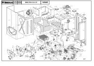
Hydro Unit – Exploded View<br />
Quick Reference Guide - Page 6<br />
1 : Expansion vessel<br />
2 : Hi pressure switch (4.15 MPa)<br />
3 : Temperature sensor (for Heat pump outlet -TWO)<br />
4 : Pressure sensor<br />
5 : Heat exchanger<br />
6 : Flow switch (13.0 L/min 17.5 L/min)<br />
7 : Temperature sensor (for refrigerant -TC)<br />
8 : Temperature sensor (for water inlet -TWI)<br />
9 : Drain nipple<br />
10 : Water inlet connection<br />
11 : Refrigerant liquid connection<br />
12 : Air relief valve<br />
13 : Pressure relief valve (0.3 MPa (3 bar))<br />
14 : Thermal protector (auto)<br />
15 : Temperature sensor (for water outlet THO)<br />
16 : Thermal protector (Single operation)<br />
17 : Water pump<br />
18 : Backup heater (3 kW, 3 kW x 2, 3 kW x 3)<br />
19 : Manometer<br />
20 : Water outlet connection<br />
21 : Refrigerant gas connection
Refrigerant Piping<br />
Refrigerant Pipe Lengths and Height<br />
The length and height of the refrigeration pipe must be within the following values.<br />
Minimum Pipe Length<br />
HWS-802H-E : 5 m<br />
HWS-1102H-E : 3 m<br />
HWS-1402H-E : 3 m<br />
Maximum Pipe Length and Height<br />
H: Max. ±30 m (above or below)<br />
L: Max. 30 m<br />
Quick Reference Guide - Page 7<br />
Note<br />
The maximum pipe length cannot be increased using additional<br />
refrigerant.<br />
Refrigeration and Water Cycle Diagrams<br />
Hydro Unit<br />
Expansion vessel<br />
Air vent valve<br />
Pressure<br />
relief<br />
valve<br />
Pressure<br />
Gauge<br />
THO<br />
Sensor<br />
Thermal<br />
Protector<br />
Refrigerant pipe<br />
at gas side<br />
(Outer ø15.88)<br />
Hi_P_Switch<br />
TWO<br />
Sensor<br />
Pump<br />
Water Out<br />
(1 1/4")<br />
Refrigerant pipe<br />
at liquid side<br />
(Outer ø9.52)<br />
P_Sensor<br />
TC<br />
Sensor<br />
Backup heater<br />
Flow_Switch<br />
TWI<br />
Sensor<br />
Water IN<br />
(1 1/4")<br />
Water Heat exchanger
Outdoor Unit<br />
Quick Reference Guide - Page 8<br />
HWS-802H-E<br />
HWS-1102H-E, 1402H-E
Quick Reference Guide - Page 9<br />
Water Piping<br />
• Install water pipes according to the regulations of respective countries.<br />
• Install water pipes in a freeze-free place.<br />
• Make sure that water pipes have sufficient pressure resistance (The setting value of the pressure<br />
relief valve is 0.3 MPa).<br />
• Do not use zinc plated water pipes. When steel pipes are used, insulate both ends of the pipes.<br />
Water Connections<br />
• Install a strainer with 30 to 40 meshes (procure locally) at<br />
the water inlet of the Hydro Unit.<br />
• Install drain cocks (procure locally) for water charge and<br />
discharge at the lower part of the Hydro Unit.<br />
Water Piping Limitations<br />
Design the water pipe length within the QH<br />
characteristics of the pump (flow-rate and pump<br />
head).<br />
The maximum height difference for the water pipes is<br />
7 metres.<br />
Piping to hot water tank (option)<br />
Water supplied to the hot water cylinder is branched by a<br />
motorized 3-way valve (procured locally).<br />
Connect the hot water cylinder to port A (open when<br />
energized) of the valve.<br />
Piping to 2-zone operation (option)<br />
To perform 2-zone temperature control circulate water using another pump (procured locally)<br />
through a motorized mixing valve (procured locally) and a buffer tank (procured locally).
Quick Reference Guide - Page 10<br />
Checking water volume and initial pressure of expansion vessel<br />
The expansion vessel of the Hydro Unit has a capacity of 12 litres.<br />
The initial pressure of the expansion vessel is 0.1 MPa (1 bar).<br />
The suggested initial water charge is 0.2MPa (2 bar).<br />
The pressure of the safety valve is 0.3 MPa (3 bar).<br />
Verify whether the capacity of the expansion vessel is sufficient using the following expression. If<br />
the volume is insufficient, install an appropriate external expansion vessel.<br />
V<br />
Action<br />
< 12 L Internal Expansion Vessel Size OK<br />
> 12 L<br />
Internal Expansion Vessel Size too small.<br />
Install appropriate external expansion vessel<br />
V: Necessary total vessel capacity (L)<br />
Ɛ: Water expansion coefficient at average hot water temperature<br />
Vs: Total water volume in the closed system (Do not include Hot Water Cylinder)<br />
P1: System pressure at tank setting position (Mpa_abs*).<br />
(Pipe inner pressure during pump operation before heating device operates = water supply<br />
pressure)<br />
P2: Maximum pressure used during operation at tank setting position (MPa_abs*).<br />
(= safety valve setting pressure)<br />
* The absolute pressure value (abs.) is obtained by adding the atmospheric pressure (0.1 MPa (1<br />
bar)) to the gauge pressure.<br />
Water temperature and expansion coefficient (Ɛ)<br />
Hot water temperature<br />
(°C)<br />
Expansion rate<br />
Water temperature and expansion coefficient (Ɛ)<br />
Hot water temperature<br />
(°C)<br />
Expansion rate<br />
(Ɛ)<br />
(Ɛ)<br />
0 0.0002 50 0.0121<br />
4 0.0000 55 0.0145<br />
5 0.0000 60 0.0171<br />
10 0.0003 65 0.0198<br />
15 0.0008 70 0.0229<br />
20 0.0017 75 0.0258<br />
25 0.0029 80 0.0292<br />
30 0.0043 85 0.0324<br />
35 0.0050 90 0.0961<br />
40 0.0078 95 0.0967<br />
45 0.0100 - -<br />
Example<br />
Maximum Hot Water temperature: 55°C, initial<br />
water charge: 0.2MPa and system volume: 200 L.<br />
The calculated Vessel capacity (V) is 11.6 L:-<br />
11.6 =<br />
0.0145 x 200<br />
1 -<br />
(0.2+0.1)<br />
(0.3+0.1)<br />
In this case V < 12 L therefore the internal<br />
expansion vessel is sufficient.<br />
There is no need to install an external expansion<br />
vessel.
Quick Reference Guide - Page 11<br />
Pump operation / configuration<br />
Change Pump speed, so that water flow is always greater than the minimum flow rate. If water flow<br />
is lower than the minimum rate during operation, the unit detects error.<br />
Water charging<br />
Charge water until the pressure gauge shows 0.2 MPa (2 bar).<br />
Hydraulic pressure may drop when the trial run begins. In that case, add water.<br />
Air may enter if the charged hydraulic pressure is low.<br />
Loosen the purge valve cap by two turns to release air.<br />
Loosen the cap of the pressure relief valve to release air.<br />
Water may come out of the pressure relief valve.<br />
Release the air completely from the water circuit. Failure to do so<br />
may disable correct operation.<br />
Water quality<br />
The water used must satisfy EN directive 98/83 EC.<br />
Piping insulation<br />
It is recommended that insulation treatment be applied to all pipes. To perform optional cooling<br />
operation, apply insulation treatment of 20 t or more to all pipes.
Electrical Connections<br />
Quick Reference Guide - Page 12<br />
E Box layout<br />
Terminal Block Connections
Power Lines Schematic<br />
Quick Reference Guide - Page 13<br />
Control Lines Schematic
Electrical supply / cable specifications<br />
Wiring specifications (power line)<br />
Description<br />
Outdoor unit power<br />
POWER<br />
SUPPLY<br />
Maximum<br />
current<br />
Installation<br />
fuse rating<br />
Quick Reference Guide - Page 14<br />
Cable size<br />
14 kW 230 V ~ 50 Hz 22.8 A 25 A 2.5 mm² or more<br />
11 kW 230 V ~ 50 Hz 22.8 A 25 A 2.5 mm² or more<br />
8 kW 230 V ~ 50 Hz 20.8 A 25 A 2.5 mm² or more<br />
Connection<br />
destination<br />
L , N<br />
Outdoor-Hydro – – 1.5 mm² or more 1 , 2 , 3<br />
Hydro inlet heater<br />
power<br />
3 kW 230 V ~ 50 Hz 13 A 16 A 1.5 mm² or more L , N (TB02)<br />
6 kW 400 V 3N ~ 50 Hz 15 A (13 A x 2P) 25 A 2.5 mm² or more L1 , L2 , L3<br />
9 kW 400 V 3N ~ 50 Hz 23 A (13 A x 3P) 25 A 2.5 mm² or more N (TB02)<br />
Hydro cylinder heater power 230 V ~ 50 Hz 12 A 16 A 1.5 mm² or more L , N (TB03)<br />
Hydro - cylinder – 12 A – 1.5 mm² or more 1 , 2 (TB03)<br />
Wiring specification (control line)<br />
Description<br />
Line spec<br />
Maximum<br />
current<br />
Maximum<br />
length<br />
Cable Size<br />
3-way valve control 2 line or 3 line 100 mA 12 m 0.75 mm² or more<br />
Mixing valve control 3 line 100 mA 12 m 0.75 mm² or more<br />
Connection<br />
destination<br />
7 , 8 , 9<br />
(TB05)<br />
1 , 2 , 3<br />
or<br />
2 , 3 , 4<br />
(TB04)<br />
2-zone thermo sensor 2 line 100 mA 5 m 0.75 mm² or more C , D (TB06)<br />
Cylinder thermo sensor<br />
2+GND (shield<br />
wire)<br />
100 mA 5 m 0.75 mm² or more A , B (TB06)<br />
Second remote controller 2 line 50 mA 50 m 0.75 mm² or more 1 , 2 (TB07)<br />
Control parts specifications<br />
Description<br />
Motorized 3-way valve (for<br />
hot water)<br />
Motorized 2-way valve (for<br />
cooling)<br />
Motorized mixing valve type<br />
1 (for 2-zone)<br />
Power<br />
AC 230 V<br />
Maximum<br />
current<br />
100 mA<br />
Type<br />
Spring return type Note: 3-wire SPST and SPDT type can be<br />
used by changing the function code.<br />
AC 230 V 100 mA spring return type (normally open )<br />
AC 230 V<br />
100 mA<br />
60 sec 90º. SPDT type Note: SPST and 20 to 240 sec type<br />
can be used by changing the function code.<br />
Output line specifications<br />
Description<br />
Output<br />
Maximum<br />
current<br />
Max<br />
voltage<br />
Maximum<br />
length<br />
External pump No. 1 AC230V 1 A – 12 m<br />
External booster heater AC230V 1 A – 12 m<br />
Boiler control<br />
ALARM Output<br />
Operation Output<br />
Defrost Output<br />
Nonvoltage<br />
0.5 A AC230 V 12 m<br />
contacts 1 A DC24 V 12 m<br />
Nonvoltage<br />
0.5 A AC230 V 12 m<br />
contacts 1 A DC24 V 12 m<br />
Nonvoltage<br />
0.5 A AC230 V 12 m<br />
contacts 1 A DC24 V 12 m<br />
Nonvoltage<br />
0.5 A AC230 V 12 m<br />
contacts 1 A DC24 V 12 m<br />
Interlocked with the Hydro Unit<br />
pump<br />
Output as required when outdoor<br />
air temperature is -20°C or less<br />
Output as required when outdoor<br />
air temperature is -10°C or less
Quick Reference Guide - Page 15<br />
Input line specifications<br />
Description Input Maximum length<br />
Emergency stop control Non-voltage 12 m<br />
Cylinder thermostat input Non-voltage 12 m<br />
Cooling thermostat input Non-voltage 12 m<br />
Heating thermostat input Non-voltage 12 m<br />
CAUTION<br />
Earthing arrangements<br />
The Hydro Unit and related equipment must be earthed in accordance with your local and national<br />
electrical regulations.<br />
It is essential that the equipment is earthed to prevent the electric shock and damage to the<br />
equipment.<br />
Electrical connection to hydro unit<br />
• Remove the front cover and the electrical box cover from the Hydro Unit.<br />
• The Hydro Unit power cable must be sized in accordance with refer to “Electrical supply/cable<br />
specifications”.<br />
• Connect the Hydro Unit power cable to Terminal 02 as shown below.<br />
Single Phase Units: Live conductor – Terminal L1<br />
Neutral conductor – Terminal L2<br />
Three Phase Units:<br />
Earth conductor – Earth terminal<br />
Phase 1 conductor – Terminal L1<br />
Phase 2 conductor – Terminal L2<br />
Phase 3 conductor – Terminal L3<br />
Neutral conductor – Terminal N<br />
Earth conductor – Earth<br />
• Ensure the Hydro Unit power cable is secured using the cable clamp fitted in the electrical box.<br />
• Ensure the Hydro Unit power cable connection terminals are tight.<br />
Outdoor unit to hydro unit electrical connection<br />
• Ensure electrical circuits are isolated before commencing work.<br />
• The Outdoor Unit to Hydro Unit interconnecting cable must be sized in accordance with refer to<br />
“Electrical supply/cable specifications”.<br />
• Connect the Outdoor Unit to Hydro Unit interconnecting cable as shown in the diagram above.<br />
• Ensure the Outdoor Unit to Hydro Unit interconnecting cable is secured using the cable clamp<br />
fitted in the electrical box.<br />
• Ensure the Outdoor Unit to Hydro Unit interconnecting cable connection terminals are tight.
Electrical connection for external booster heater<br />
Quick Reference Guide - Page 16<br />
CAUTION<br />
The maximum current available from the booster heater output is 1 A. Do not connect the<br />
booster heater directly to Terminal Block 05 on the Hydro Unit. The AC230 V 1 A output<br />
from the Hydro Unit must only be used to energize an external contactor (Supplied locally).<br />
• The booster heater can be installed only for room heating and cannot be used for hot water<br />
supply.<br />
• Install the booster heater downstream of the 3-way valve on the indoor unit side.<br />
• The booster heater is an external heater, supplied locally, used to assist the Hydro Unit during<br />
low ambient conditions.<br />
• The output from the Hydro Unit is only enabled when the outdoor air temperature is less than -<br />
20°C.<br />
• Ensure the external booster heater is installed and set up in accordance with all Local, National<br />
and International regulations.<br />
• Connect the coil, of the field supplied contactor, to terminals 5 & 6 on Terminal Block 05. The<br />
contactor will energize in the event of low ambient conditions.<br />
• A separate dedicated electrical supply must be used for the external booster heater. This must<br />
be connected through the contacts on the field supplied contactor (see diagram below):-<br />
Electrical connection for external additional pump (P2)<br />
CAUTION<br />
The maximum current available from the additional pump output is 1 A. Do not connect the<br />
additional pump directly to Terminal Block 05 on the Hydro Unit. The AC230 V 1 A output<br />
from the Hydro Unit must only be used to energize an external contactor (Supplied locally).<br />
• The Hydro Unit has the facility to connect an additional circulating pump, if required, into the<br />
heating or cooling system.<br />
• Install the external pump so that its motive power does not affect the internal pump.<br />
• The output for the pump is synchronized with the operation of the main circulating pump (P1)<br />
inside the Hydro Unit.<br />
• Connect the coil, of the field supply contactor, to terminals 1 & 2 on Terminal Block 05.<br />
• A separate dedicated electrical supply must be used for the additional pump. This must be<br />
connected through the contacts on the field supplied contactor (see diagram below):-
2-way valve (for cooling) connection<br />
Required Valve Specification:<br />
Electrical Specification: 230 V; 50 Hz;
Quick Reference Guide - Page 18<br />
3-way mixing valve connection<br />
Required Actuator Specification<br />
Electrical Specification:230 V; 50 Hz;
Setting DIP Switches on the Board<br />
in the Hydro Unit<br />
• Detach the front cover and the electric parts box cover of<br />
the Hydro Unit.<br />
• Set the DIP switches on the main board.<br />
Quick Reference Guide - Page 19<br />
SW10<br />
1<br />
Description<br />
Internal pump P1 operating<br />
mode<br />
Default setting<br />
Switch mode<br />
Alternate<br />
Continuous operation OFF ON HP synchronized<br />
3 External P2 pump operation Continuous operation OFF ON<br />
Interlocked with the<br />
internal pump<br />
synchronized with P1.<br />
SW11<br />
Description<br />
Switch mode<br />
Default setting<br />
Alternate<br />
1<br />
Internal backup heater<br />
operation<br />
Operate OFF ON Not operate<br />
2<br />
Hot water cylinder heater<br />
operation<br />
Operate OFF ON Not operate<br />
3 Booster heater operation Operate OFF ON Not operate<br />
SW12<br />
Description<br />
Default setting<br />
Switch mode<br />
1 Hot water supply operation Valid OFF ON Invalid<br />
2 Zone 1 operation Valid OFF ON Invalid<br />
3 Zone 2 operation Invalid OFF ON Valid<br />
SW13<br />
Description<br />
1 Type of motorized 3-way valve<br />
Default setting<br />
• 2-wire spring return type<br />
• 3-wire SPST type<br />
Switch mode<br />
Alternate<br />
Alternate<br />
OFF ON 3-wire SPDT type<br />
2 Interlocking with boiler Invalid OFF ON Valid<br />
3 Auto restart for power failure Auto restart OFF ON Manual restart<br />
SW02<br />
Description<br />
Default setting<br />
Switch mode<br />
4 Room thermostat Invalid OFF ON Valid<br />
Alternate
Hydro Unit Remote Control<br />
Buttons and Functions<br />
Quick Reference Guide - Page 20<br />
1. TEMP. button:<br />
2. SCHEDULE<br />
button:<br />
Changes the set temperature for<br />
each operation mode (ZONE1/2 hot<br />
water) by 1°C step.<br />
Sets the current time and<br />
scheduled weekly operation.<br />
3. TIME button: Changes time for current time<br />
setting and scheduled weekly<br />
operation setting with ▼ and ▲<br />
buttons.<br />
4. SET button:<br />
5. CL button:<br />
6. DAY button:<br />
7. STEP button:<br />
Determines the entered current<br />
time setting and scheduled weekly<br />
operation setting.<br />
Clears settings for the current time<br />
and scheduled weekly operation.<br />
Sets days of the week for current<br />
time setting and scheduled weekly<br />
operation setting.<br />
Specifies switching STEP number<br />
in a day for weekly schedule.<br />
10. NIGHT button:<br />
11. AUTO TEMP.<br />
button:<br />
12. OPERATE<br />
MODE button:<br />
13. ZONE1, 2<br />
button:<br />
14. ANTI BACTERIA<br />
button:<br />
15. HOT WATER<br />
BOOST button:<br />
16. HOT WATER<br />
button:<br />
Controls the night set back<br />
operation.<br />
Switches setting temperature<br />
automatically according to outside<br />
temperature. (Pressing this button<br />
long changes the mode to data<br />
setting mode).<br />
Selects ZONE1/2 operation mode<br />
(heating or cooling).<br />
Turns on/off the zone (floor<br />
heating/radiator/FCU) operation.<br />
Regularly increases the hot water<br />
temperature in the tank for<br />
sterilization. (Pressing this button<br />
long changes the mode to data<br />
setting mode).<br />
Boosts boiling when high tapping<br />
temperature is required temporarily.<br />
Turns on/off hot water operation.<br />
8. TEST button:<br />
Used for test run or service.<br />
17. SELECT button:<br />
Selects an operation mode when<br />
changing the set temperature of<br />
each operation mode.<br />
9. FROST<br />
PROTECTION<br />
button:<br />
Controls minimum operation for<br />
unused period (going out,<br />
absence,etc.) for anti freezing.<br />
NOTE<br />
Some functions are not provided depending on the system specification in use.
Display Explanation<br />
Quick Reference Guide - Page 21<br />
18: ZONE1, ZONE2 20: HOT WATER<br />
Display Description Display Description<br />
Lights when floor heater or radiator<br />
is connected (when the system has<br />
floor heater or radiator).<br />
ZONE1 selected for Temperature<br />
to be changed.<br />
Lights when system configured to<br />
have 2 zones.<br />
Lights when hot water supply system is<br />
connected (when the system has hot<br />
water supply).<br />
ZONE2 selected for Temperature<br />
to be changed.<br />
HOT WATER selected for Temperature<br />
to be changed.<br />
Lights during heating or cooling<br />
operation using the heat pump.<br />
Lights when hot water supply operation<br />
is performed by heat pump.<br />
Lights when the internal heater is<br />
energized during heating<br />
operation.<br />
Lights when the internal heater is<br />
energized during hot water supply<br />
operation.<br />
Lights when heating is selected.<br />
Lights during hot water supply operation.<br />
Lights when cooling is selected.<br />
Lights while hot water boost is activated.<br />
Lights when the FROST<br />
PROTECTION button is pressed<br />
and goes out when the button is<br />
pressed again.<br />
Lights when the ANTI BACTERIA button<br />
is pressed and goes out when the button<br />
is pressed again.<br />
Lights when Auto operation is<br />
selected.<br />
Lights when unit enters the data set<br />
mode.<br />
°C<br />
Displays heating/cooling set<br />
temperature. (Heating: 20 to 55°C,<br />
factory setting: Auto, cooling: 10 to<br />
30°C) Goes out when Auto<br />
operation is selected.<br />
Lights when the set temperature or<br />
sensor's water temperature is<br />
displayed with the 7-segment<br />
indicator.<br />
°C<br />
Displays hot water set temperature.<br />
(40 to 80°C, factory setting: 65°C)<br />
Lights when the set temperature or<br />
sensor's water temperature is displayed<br />
with the 7-segment indicator.
Display Explanation (cont.)<br />
Quick Reference Guide - Page 22<br />
19: TIMER 21: OPERATION<br />
Display Description Display Description<br />
Clock: Displays the current time<br />
(AM or PM).<br />
Displays days of the week (Sunday<br />
to Saturday).<br />
Lights when the NIGHT button is<br />
pressed and goes out when the<br />
button is pressed again.<br />
Lights when night time quiet<br />
operation is set.<br />
Indicates scheduled operation 1<br />
status (including setting time).<br />
Displays the scheduled operation<br />
step when the scheduled operation<br />
STEP1-5 program is set.<br />
Lights during time setting and<br />
scheduled operation setting.<br />
Lights while internal pump (P1) or<br />
external pump (P2) is driven.<br />
Lights during backup operation only by<br />
the heater.<br />
Lights when the unit enters the data set<br />
mode and goes out when the unit exits<br />
the data set mode.<br />
Lights when the unit enters the service<br />
mode and goes out when the unit exits<br />
the service mode.<br />
Lights when an error occurs and goes<br />
out when the error is cleared.<br />
Lights for two seconds when settings are<br />
completed.<br />
Lights for two seconds when settings<br />
failed.<br />
Function Code Access<br />
Set function codes for various operation modes, input using the remote controller.<br />
There are 2 types of settings:-<br />
1) Hydro Unit function code setting.<br />
2) Remote controller function code setting.<br />
Setting procedure for Hydro Unit function code<br />
1. Press the TEST + SET + SELECT buttons<br />
for four seconds or more to enter the hydro unit function code setting mode.<br />
2. Set the function code number with the TEMP. buttons<br />
(CODE No.: 01 to 91).<br />
3. Set data (DATA) with the TIME buttons .<br />
4. Press the SET button to confirm the settings.<br />
5. The CL button is enabled only before the SET button is<br />
pressed and the function code is changed.<br />
6. Press the TEST button to finish the settings.<br />
Setting procedure for Remote Controller function code<br />
1. Press the TEST + CL + TEMP. ▼ buttons for four seconds<br />
or more to enter the remote controller function code setting mode.<br />
2. Set the function code number with the TEMP. buttons<br />
(CODE No.: 01 to 13).<br />
3. Set data (DATA) with the TIME buttons .<br />
4. Press the SET button to determine the settings.<br />
5. The CL button is enabled only before the SET button is<br />
pressed and the function code is changed.<br />
6. Press the TEST button to end the settings.
Main setting items<br />
Quick Reference Guide - Page 23<br />
(1) Setting Hot Water Temperature Range (function code 18 to 1F)<br />
• Set the temperature range for heating (zone 1, zone 2), cooling, and hot water.<br />
• The upper-limit and lower-limit temperatures of each mode can be set.<br />
(2) Setting Heat Pump Operation Conditions for Hot Water Supply (function code 20 and 21)<br />
• Set the heat pump start water temperature and heat pump stop water temperature.<br />
• The heat pump starts working when the water temperature lowers below the set start water temperature. It<br />
is recommended that the default value be used.<br />
(3) Compensating Hot Water Temperature (function code 24 and 25)<br />
• Compensate the target temperature from the remote controller set temperature when the hot water<br />
temperature lowers below the set outside air temperature.<br />
(4) Setting Hot Water Boost (function code 08 and 09)<br />
• Set the control time and target temperature when the HO T WATER BOOST button on the remote<br />
controller is pressed.<br />
(5) Setting Anti-Bacteria<br />
• Set the control for the hot water cylinder when ANTI BACTERIA is set with the remote controller.<br />
• Set the target temperature, control period, start time (24-hour notation), and target temperature retention<br />
period.<br />
• Make this control setting according to regulations and rules of respective countries.<br />
(6) Setting Priority Mode Temperature<br />
• Set the outside air temperature that changes the preferred operation mode.<br />
• Hot Water - Heating Switching Temperature<br />
Heating operation takes precedence when the temperature lowers the set temperature.<br />
• Boiler HP Switching Temperature<br />
When the temperature lowers the set temperature, the HP operation stops and the external boiler output is<br />
made.<br />
(7) Setting Heating Auto Mode Temperature (function code 27 to 31)<br />
• Compensate the target temperature when Auto is set for temperature setting on the remote controller.<br />
• The outside air temperature can be set to one of three points (T1, T2, and T3) within a range of -20 to 20°C.<br />
• The target temperature can be set to a value from 20 to 55°C.<br />
• However, A > B > C > D > E.<br />
• The entire curve can be adjusted plus and minus 5°C by function code 27.<br />
(8) Setting Frost Protection Temperature (function code 3A to 3B)<br />
• Set the function when the FROST PROTECTION button on the remote controller is pressed.<br />
• Set enabling/disabling of this function and the target water temperature.<br />
• If disabling is set, the frost protection operation is not performed even wh en the FROST PROTECTION button<br />
is pressed.<br />
(9) Setting Frequency of Output to Internal Heater (function code 33 to 34)<br />
• The increase/decrease time is used to set the response time.<br />
(10)Setting Night Setback (function code 26. remote controller function code 0F to 11)<br />
• Set the function when the NIGHT button on the remote controller is pressed.<br />
• Set enabling/disabling of this function, reduction temperature, start time, and end time.<br />
• If disabling is set, the night setback operation is not performed even when the NIGHT<br />
button is pressed.
Main setting item (cont.)<br />
Quick Reference Guide - Page 24<br />
(11)Setting 2-Way Valve (for Cooling) Operation (function code 3C)<br />
• When using both cooling and heating operations and there is an indoor unit only for heating (such as floor<br />
heating), install the 2-way valve and set this function code.<br />
(12)Setting 3-Way Valve Operation (function code 54)<br />
• This setting is not necessary for normal installation. Make this setting to invert the logic circuit in case ports<br />
A and B of the 3-way valve are wrongly attached and it cannot be rectified on site.<br />
(13)Mixing valve types and setting<br />
• Set the time period from full close to full open of the 2-zone control mixing valve. Set a value that is 1/10 of<br />
the actual time.<br />
(14)Setting Heating/Hot Water Switching when Boiler Is Used (function code 3E)<br />
• When boiler is used, make this setting to operate the Hydro Unit by the instruction from the boiler.<br />
(15)Setting Heat Pump Operating Time for Hot Water Supply Operation<br />
• Set the time period from the start of heat pump run to the start of heater energization at the beginning of hot<br />
water supply operation. If a long period is set, it takes long time for heating water.<br />
(16)Setting Cooling ON/OFF<br />
• Set this function when performing cooling operation.<br />
(17)Remote controller time indication<br />
• 24-hour or 12-hour notation is selected for the timer.<br />
(18)Setting Nighttimes Quiet Operation<br />
• Issue an instruction for low-noise mode operation to the outdoor unit. Enabling/disabling of this function, start<br />
time, and end time can be set.<br />
(19)Setting Alarm Tone<br />
• The remote controller alarm tone can be set.<br />
Function Code List<br />
Function<br />
Function Code<br />
Number<br />
Hydro<br />
Remote<br />
Unit C ontroller<br />
Range<br />
Default<br />
Zone 1 - heating upper temperature limit °C 1A - 37 ~55 55<br />
Zone 1 - heating lower temperature limit °C 1B - 20 ~ 37 20<br />
Zone 2 - heating upper limit temperature °C 1C - 37 ~55 55<br />
Setting<br />
Zone 2 - heating lower limit temperature °C 1D - 20 ~ 37 20<br />
Temperature<br />
Range Cooling mode - upper temperature limit °C 18 - 18 ~ 30 25<br />
Cooling mode - lower temperature limit °C 19 - 10 ~ 18 10<br />
Hot water - upper temperature limit °C 1E - 50 ~ 75 75<br />
Hot water - lower temperature limit °C 1F - 40 ~ 60 40<br />
Hot Water Heat pump start temperature °C 20 - 20 ~ 45 38<br />
Operation Heat pump stop temperature °C 21 - 40 ~ 50 45<br />
Hot Water<br />
T emperature<br />
Compensation<br />
Hot Water Boost<br />
Anti - Bacteria<br />
Priority Mode<br />
Temperature compensation - start outside air<br />
temperature °C<br />
24 - -20 ~ 10 0<br />
Compensation temperature °C 25 - 0 ~ 15 3<br />
Operation time x 10 min 08 - 3 ~ 18 6<br />
Setting temperature °C 09 - 40 ~ 75 75<br />
Setting temperature °C 0A - 70 ~ 75 75<br />
Start cycle (day) - 0D 0 ~ 10 7<br />
Start time (hour) - 0C 0 ~ 23 22<br />
Operation time (min)<br />
0B - 0 ~ 60 30<br />
Hot water and heating switching<br />
temperature °C<br />
22 - -20 ~ 20 0<br />
Boiler and heat pump switching<br />
temperature °C<br />
23 - -20 ~ 20 -10
Function Code List (cont.)<br />
Heating<br />
Auto Curve<br />
Settings<br />
Frost Protection<br />
Back Up Heater<br />
Control<br />
Night Setback<br />
Function<br />
Function Code Number<br />
Hydro Unit<br />
Quick Reference Guide - Page 25<br />
Remote<br />
Controller<br />
Range<br />
Default<br />
Outside temperature T1 °C 29 - -15 ~ 0 -10<br />
Outside temperature T2 °C - - 0 0<br />
Outside air temperature T3 °C 2B - 0 ~ 15 10<br />
Setting temperature A at -20 °C 2C - 20 ~ 55 40<br />
Setting temperature B at T1°C 2D - 20 ~ 55 35<br />
Setting temperature C at T2°C 2E - 20 ~ 55 30<br />
Setting temperature D at T3°C 2F - 20 ~ 55 25<br />
Setting temperature E at +20°C 30 - 20 ~ 55 20<br />
Ratio of Zone 2 in Zone 1 Auto mode (%) 31 - 0 ~ 100 80<br />
Temperature shift of entire Auto curve (°C) 27 - -5 ~ 5 0<br />
Function 0 = Valid; 1 = Invalid 3A - 0 ~ 1 1<br />
Setting temperature °C 3B - 8 ~ 20 15<br />
Back up heater downtime. 0=5min; 1=10min;<br />
2=15min; 3=20min<br />
Back up heater uptime. 0=10min; 1=20min;<br />
2=30min; 3=40min<br />
Zone Selection: 0=Zones 1 and Zone 2;<br />
1=Zone 1 Only<br />
33 - 0 ~ 3 1<br />
34 - 0 ~ 3 0<br />
58 - 0 ~ 1 0<br />
Change Setback temperature °C 26 - 3 ~ 20<br />
5<br />
Start time (hour) - 0E 0 ~ 23 22<br />
End time (hour) - 0F 0 ~ 23 06<br />
Room temperature control adjustment. 0=Valid;<br />
1=Invalid<br />
- 02 0 ~ 1 0<br />
Compensation for temperature °C 35 - 1 ~ 5 1<br />
Room Temperature<br />
Setting<br />
1 ~ 24<br />
Downtime Zone B (x 5min) 36 -<br />
6<br />
(5 ~ 120mins)<br />
Uptime Zone C (x5min) 37 -<br />
1 ~ 24<br />
(5 ~ 120mins)<br />
6<br />
2 Way Valve<br />
Operation Control<br />
3 Way valve<br />
Operation Control<br />
2 way valve activation for cooling.<br />
0=activated during cooling;<br />
1=not activated during cooling<br />
3 way valve activation.<br />
0=activated during hot water operation;<br />
1=not activated during hot water operation<br />
3C - 0 ~ 1 0<br />
54 - 0 ~ 1 0<br />
2 Zone Mixing<br />
V alve Drive Time<br />
Boiler & Heat<br />
Pump<br />
Synchronisation<br />
Specified Drive Time for Mixing Valve to 90°<br />
open (x 10 sec)<br />
Boiler synchronisation with heat pump.<br />
0=synchronised; 1=not synchronised<br />
Maximum<br />
Ope ration Time of Maximum heat pump operation time in hot<br />
Hot Water Heat water operation priority mode (minutes)<br />
Pump<br />
0C - 3 ~ 24 6<br />
3E - 0 ~ 1 0<br />
07 - 1 ~ 120 30<br />
Cooling Operation<br />
Activate cooling mode.<br />
0=cooling & heating mode; 02 - 0 ~ 1 1<br />
1=heating mode only
Function Code List (cont.)<br />
Function Code Number<br />
Quick Reference Guide - Page 26<br />
Function<br />
Hydro Unit<br />
Remote<br />
Controller<br />
Range<br />
Default<br />
Remote Controller<br />
Indication<br />
24 hour or 12 hour remote control display.<br />
0=24hr; 1=12hr<br />
- 05 0 ~ 1 0<br />
Outdoor Night Time<br />
Low Noise<br />
Operation<br />
0 = Function invalid<br />
1 = Function valid<br />
- 09 0 ~ 1 0<br />
Start time (hour) - 0A 0 ~ 23 22<br />
End time (hour) - 0B 0 ~ 23 06<br />
Alarm Tone Tone Switching 0: OFF, 1: ON 11 0 ~ 1 1<br />
Pump P2 remote<br />
controller Display<br />
0 = Not Shown;<br />
1 = Shown<br />
42 - 0 ~ 1 0<br />
Outdoor Forced<br />
Defrost Mode<br />
Optional ON/OFF<br />
Command<br />
Outdoor Night Time<br />
Mode Button<br />
Control Logic for<br />
Room Thermostat<br />
0 = Forced Defrost OFF;<br />
1 = Forced Defrost ON<br />
0 = a contact “ON” = Forced stop<br />
1 = b contact “OFF” = Forced stop<br />
2 = ON/OFF = Start / Stop<br />
3= HA Specification<br />
0 = Symbol displayed when mode is valid<br />
(controlled by Function Code Only);<br />
1 = Symbol displayed when mode is activated<br />
(controlled by Function Code and Button)<br />
0 = Cooling thermo on – contact open;<br />
1 = Cooling thermo on – contact close<br />
46 - 0 ~ 1 0<br />
52 - 0 ~ 3 0<br />
56 - 0 ~ 1 0<br />
57 - 0 ~ 1 0<br />
Settings by Purpose<br />
Settings when hot water supply function is not used<br />
• When the hot water supply function is not used, set DIP SW12-1 on the Hydro Unit board to ON.<br />
Setting for cooling<br />
• For Space Conditioning Units that do not perform cooling (radiators and Under floor heating, etc.), procure a<br />
motorized 2-way valve (for cooling) locally and attach it to the water pipe that is not used for cooling. Connect the<br />
valve cables (as described in Electrical section).<br />
• Press long the TEST + SET + SELECT switches on the remote controller to change the<br />
Hydro Unit function code, and change address 02 to 0, and then press the SET button to enable the function.<br />
Press the TEST<br />
button to exit the setting mode.<br />
• Stick the optional insulator for cooling to the bottom of the Hydro Unit.<br />
Settings for hot water supply<br />
• Prepare the optional hot water cylinder.<br />
• Procure a motorized 3-way (diverter) valve locally and perform piping. Connect the valve cables (as described in<br />
Electrical section).<br />
• Set DIP SW12-1 on the Hydro Unit board to OFF.<br />
• Connect the power supply unit for the hot water cylinder heater to terminals TB03 L and N of the Hydro Unit.<br />
• Connect cables between the Hydro Unit and the hot water cylinder as follows:<br />
Hydro Unit terminals TB03 (1), (2), and earth — Hot water cylinder (1), (2), and earth<br />
TB06 A, B, and earth — Hot water cylinder A, B, and earth
Quick Reference Guide - Page 27<br />
Settings by Purpose (cont)<br />
Settings for 2-zone temperature control<br />
• Procure a motorized mixing valve locally and perform piping. Connect the valve cables (as described in Electrical<br />
section).<br />
• Procure a buffer tank locally.<br />
• Procure a water pump locally, and connect its cables (as described in Electrical section).<br />
To inhibit interlocking the water pump with the internal pump of the Hydro Unit, set DIP SW10-3 on the Hydro<br />
Unit board to OFF.<br />
• Set DIP SW12-3 on the Hydro Unit board to ON.<br />
Attach the temperature sensor (TFI) connected to terminals TB06 C and D of the Hydro Unit near the hot water<br />
inlet of the Hydro Unit.<br />
• Contact the temperature sensor closely with the pipe, fix it with aluminium tape or the like, and then perform<br />
insulation treatment for the sensor.<br />
• Fix TFI sensor on the room heating supply pipe by using the connector procured in locally.<br />
• Cover the cables with insulation tube (minimum 1 mm) or conduit so that the user cannot touch them directly.<br />
• Connect the functional earth wire of TFI sensor in the tank unit.<br />
• Cover the TFI sensor's cables and sensor with insulation tube (minimum 1 mm) shown in the diagram on the<br />
right.<br />
Test Run<br />
Use operation buttons usually to conduct a test run.<br />
If the outside air temperature or water temperature is outside the setting value range, press the TEST button on<br />
the remote controller and then start a test run. Since the protection setting is disabled in the TEST mode, do not<br />
continue a test run longer than 10 minutes.<br />
• Press the TEST<br />
button on the remote controller. An indication “TEST” appears on the remote controller.<br />
• Press the ZONE1, 2 button and select “heating” with the OPERATE MODE button.<br />
The pump is activated in 30 seconds.<br />
If air is not released completely, the flow rate switch is activated to stop operation. Release air again according to the<br />
piping procedure. Little air bite is discharged from the purge valve.<br />
• Check that the air bite sound disappears.<br />
• Check that the hydraulic pressure has become the predetermined pressure 0.1 to 0.2 MPa (1 to 2 bar). If the<br />
hydraulic pressure is insufficient, replenish water.<br />
• Heating operation starts. Check that the hydro unit starts heating.<br />
• Press the OPERATE MODE button and select “cooling.”<br />
• Cooling operation starts. Check that the hydro unit starts cooling and that the floor heating system is not cooled.<br />
• Press the ZONE1, 2<br />
button to stop operation.<br />
• Press the HOT WATER button to start hot water supply operation.<br />
• Check that there is no air bite.<br />
• Check that hot water is present at the connection port of the hot water cylinder.<br />
• Press the HOT WATER<br />
• Press the TEST<br />
button to stop the hot water supply operation.<br />
button to exit the test mode.
Quick Reference Guide - Page 28<br />
Sensor Temperature Monitoring Function<br />
The sensor sensing temperature is displayed on the remote controller. This function allows you to make sure whether<br />
the sensor is installed properly.<br />
1) Press the TEST + CL buttons for four seconds or more.<br />
2) Select the Code No. with the TEMP. buttons.<br />
3) Press the TEST button to exit the test mode.<br />
Code No. Location Indication<br />
06 Return water temperature °C<br />
08 Hot water temperature °C<br />
09 Hydro unit 2-zone sensor temperature °C<br />
0A Hot water cylinder temperature sensor °C<br />
0B<br />
Motorized mixing valve position<br />
60 Heat exchanger temperature °C<br />
61 Outside air temperature °C<br />
62 Outdoor unit Refrigerant discharge temperature °C<br />
63 Refrigerant intake temperature °C<br />
6A<br />
Current value (in the inverter) A<br />
70 Compressor operating frequency<br />
F4<br />
Hydro unit AC pump total operating hours x100 hours<br />
F5 Operating hours Hot water cylinder heater total operating hours x100 hours<br />
F6<br />
Hydro unit heater total operating hours x100 hours<br />
Fault Symptoms<br />
Symptom Possible cause Corrective action<br />
Room is not heated or<br />
cooled. Water is not hot<br />
enough.<br />
Nothing is displayed on<br />
the remote controller.<br />
Flow rate switch is<br />
activated. Error code<br />
[A01]<br />
Hot water leaks from<br />
pressure relief valve.<br />
Incorrect remote controller setting<br />
Incorrect function code setting<br />
Backup heater disconnected<br />
Insufficient capacity<br />
Sensor defect<br />
Power is not supplied.<br />
Incorrect setting<br />
Air bite in the pump<br />
Low hydraulic pressure<br />
Strainer is clogged.<br />
Large resistance on the hydro side<br />
Malfunction of motorized 3-way<br />
valve for hot water supply<br />
Excessive hydraulic pressure<br />
Insufficient capacity of expansion<br />
tank<br />
Expansion tank failure<br />
Check remote controller operation and temperature<br />
setting<br />
Check function code setting with the function code<br />
table.<br />
Check backup heater and bimetal thermostat.<br />
Check selection of equipment.<br />
Check whether temperature sensor is installed at<br />
the normal position.<br />
Check power supply wiring.<br />
Check DIP switch setting on the Hydro Unit board.<br />
Check the setting with the function code table.<br />
Release air completely according to the procedure.<br />
Set hydraulic pressure considering pipe height, and<br />
replenish water until manometer shows a value of<br />
set hydraulic pressure or more.<br />
Clean the strainer.<br />
Widen water path to the hydro unit or adopt a<br />
bypass valve.<br />
Check wiring and parts.<br />
Set hydraulic pressure considering pipe height, and<br />
replenish water until manometer shows a value of<br />
set hydraulic pressure or more.<br />
Check expansion tank capacity compared to total<br />
water amount. If it is insufficient, install another<br />
expansion tank.<br />
Check the air pressure.
Alarm Indications<br />
Alarm<br />
indication<br />
E03<br />
E04<br />
F03<br />
F10<br />
F11<br />
F14<br />
F17<br />
F18<br />
F23<br />
F29<br />
F20<br />
Alarm description and generation/reset conditions<br />
Quick Reference Guide - Page 29<br />
Regular communication error between hydro unit and remote controller (system controller) If there is no<br />
regular communication from the remote controller for three minutes, the hydro unit regards it as no<br />
remote controller. If there is no communication from both sides, alarm E03 occurs. Auto-reset: When<br />
successful regular communication is made<br />
Regular communication error between hydro unit and outdoor unit When serial signal from the outdoor<br />
unit cannot be received though normal serial signal is sent to the outdoor unit 1) When serial signal<br />
cannot be received continuously for 60 seconds (S code communication) 2) Communication is still not<br />
successful for 80 seconds through three retries if serial signal cannot be received for 20 seconds after<br />
new communication (f code) starts When the remote controller starts operation, serial transmission<br />
starts with the new communication format. Auto-reset: When successful regular communication is<br />
made<br />
Condensing temperature TC sensor defect<br />
If short-circuit or open-circuit state continues for two seconds, an alarm occurs.<br />
Auto-reset: When normal value is confirmed<br />
Hydraulic heat exchanger inlet temperature TWI sensor defect<br />
If short-circuit or open-circuit state continues for two seconds, an alarm occurs.<br />
Auto-reset: When normal value is confirmed<br />
Hydraulic heat exchanger outlet temperature TWO sensor defect<br />
If short-circuit or open-circuit state continues for two seconds, an alarm occurs.<br />
Auto-reset: When normal value is confirmed<br />
Hot water cylinder temperature TTW sensor defect<br />
If short-circuit or open-circuit state continues for two seconds, an alarm occurs.<br />
Auto-reset: When normal value is confirmed<br />
Floor inlet temperature TFI sensor defect<br />
If short-circuit or open-circuit state continues for two seconds, an alarm occurs.<br />
Auto-reset: When normal value is confirmed<br />
Internal heater outlet temperature TWO sensor defect<br />
If short-circuit or open-circuit state continues for two seconds, an alarm occurs.<br />
Auto-reset: When normal value is confirmed<br />
Low-pressure sensor defect<br />
If open-circuit state continues for two seconds, an alarm occurs.<br />
Auto-reset: When normal value is confirmed<br />
Hydraulic heat exchanger EEPROM defect<br />
One mismatch is detected if there is no verification ACK after data write to the EEPROM Reset<br />
condition: This alarm is inhibited while the unit is not working.<br />
(When EEPROM1K is mounted, this alarm cannot be reset.)<br />
Floor inlet temperature TFI sensor disconnection or wrong installation (This alarm is reset by stopping<br />
operation and is checked again.)<br />
F30<br />
L07<br />
L09<br />
A01<br />
A02<br />
A03<br />
A04<br />
A07<br />
A08<br />
Onboard expansion IC defect This alarm is not reset automatically.<br />
Group line in an hydro unit<br />
This alarm is checked during initial communication immediately after power-on. This alarm occurs<br />
immediately after operation start.<br />
This alarm is not reset automatically. (This alarm is inhibited while the unit is not working, but occurs<br />
again after the unit operates.)<br />
Hydro unit capacity has not been set.<br />
This alarm is checked immediately after power-on. This alarm is not reset automatically. (This alarm is<br />
inhibited while the unit is not working, but occurs again after the unit operates.)<br />
Pump defect or abnormal flow rate This alarm is not reset automatically.<br />
Excessive water temperature increase by the heating heater Auto-reset:<br />
Excessive water temperature increase in the hot water cylinder<br />
Freezing is detected. Auto-reset:<br />
High-pressure switch malfunction This alarm is not reset automatically.<br />
Low-pressure sensor malfunction This alarm is not reset automatically.
Quick Reference Guide - Page 30<br />
Alarm Indications (cont)<br />
A09 Overheat preventive operation malfunction Auto-reset: When operation mode is changed<br />
A11<br />
P31<br />
Release preventive operation malfunction This alarm occurs when the Hydro Unit enters the forcedstop<br />
zone 10 times.<br />
Self-hydro unit is stopped due to alarm of other hydro unit. When alarm occurs in an hydro unit in the<br />
group, other hydro units must also be stopped with refrigerant control.<br />
When alarm E03, L03 or L07 occurs in the header unit in the group, other hydro units must also be<br />
stopped<br />
because they do not know which header unit (remote controller) to follow.<br />
Auto-reset: When the first alarm is reset<br />
Outdoor Alarm indication<br />
Alarm<br />
indication<br />
F04<br />
F06<br />
F08<br />
Main failure part<br />
Outdoor unit discharge<br />
temperature sensor TD<br />
defect<br />
Outdoor unit temperature<br />
sensor TE or TS defect<br />
Outdoor unit outside air<br />
temperature sensor TO<br />
defect<br />
Description<br />
When open- or short-circuit of discharge temperature sensor TD is<br />
detected<br />
When open- or short-circuit of heat exchanger temperature sensor<br />
TE or TS is detected<br />
When open- or short-circuit of outside air temperature sensor TO is<br />
detected<br />
H01 Compressor breakdown<br />
When min-Hz is reached by current release control or when shortcircuit<br />
current (Idc) is detected after direct current excitation<br />
H02 Compressor locked When compressor lock is detected<br />
H03 Current detector defect<br />
When abnormal current is detected in AC-CT or phase loss is<br />
detected<br />
H06 Low-pressure system defect Ps pressure sensor defect or low-pressure protective operation<br />
L29 Other outdoor unit faults<br />
Other outdoor unit faults: 1) Inter-MCU communication error between<br />
IPDU and CDB 2) abnormal GBT heat sink temperature<br />
L31 Phase sequence error, etc.<br />
When phase sequence of 3-phase power supply is incorrect<br />
(thermostat OFF operation continued), etc.<br />
P03<br />
Abnormal outdoor unit When abnormal temperature is detected by discharge temperature<br />
discharge temperature release control<br />
P04<br />
High-pressure system<br />
defect<br />
When high-pressure switch , IOL is activated or when abnormality is<br />
detected by high-pressure release control by TE<br />
P22 Outdoor unit fan defect When over current or lock in outdoor unit fan drive circuit is detected<br />
P26 Inverter Idc operation<br />
When short-circuit protection is activated for compressor driver<br />
devices (G-Tr, IGBT)<br />
P29 Position detection error When compressor motor position detection error is detected
Outdoor Fault Diagnosis<br />
Quick Reference Guide - Page 31<br />
You can perform fault diagnosis of the outdoor unit with the LED's on the P.C. board of the outdoor unit in addition<br />
to check codes displayed on the wired remote controller of the hydro unit.<br />
Use the LED’s and check codes for various checks.<br />
Check of the current abnormal status<br />
1. Check that DIP switch SW803 is set to all OFF.<br />
2. Jot down the states of LED800 to LED804. (Display mode 1)<br />
3. Press SW800 for at least one second. The LED status changes to<br />
display mode 2.<br />
4. Check the code whose display mode 1 equals the jotted LED status and<br />
display mode 2 equals the current flashing status of LED800 to LED804<br />
from the following table to identify the cause.<br />
Check of the abnormal status in the<br />
past although the abnormal status is<br />
not occurred now.<br />
1. Set bit 1 of DIP switch SW803 to ON.<br />
2. Jot down the states of LED800 to<br />
LED804. (Display mode 1)<br />
3. Press SW800 for at least one second.<br />
The LED status changes to display<br />
mode 2.<br />
4. Find an error whose display mode 1<br />
equals the jotted LED status and display<br />
mode 2 equals the current flashing<br />
status of LED800 to LED804 from the<br />
following table to identify the error.<br />
• An outside air temperature (TO)<br />
sensor error can be checked only while<br />
an error occurs.<br />
DISPLAY MODE 1 DISPLAY MODE 2<br />
No. Cause D800 D801 D802 D803 D804 D800 D801 D802 D803 D804<br />
1 Normal ● ● ● ● ● ● ● ● ● ●<br />
2 Discharge sensor (TD) error ○ ○ ● ● ○ ● ● ◎ ● ●<br />
3 Heat exchanger sensor (TE) error ○ ○ ● ● ○ ● ◎ ◎ ● ●<br />
4 Heat exchanger sensor (TL) error ○ ○ ● ● ○ ◎ ◎ ◎ ● ●<br />
5<br />
Outside air temperature sensor (TO)<br />
error<br />
○ ○ ● ● ○ ● ● ● ◎ ●<br />
6 Suction sensor (TS) error ○ ○ ● ● ○ ● ● ◎ ◎ ●<br />
7 Heat sink sensor (TH) error ○ ○ ● ● ○ ◎ ● ◎ ◎ ●<br />
8<br />
Outdoor temperature sensor (TE/TS)<br />
connection error<br />
○ ○ ● ● ○ ◎ ◎ ◎ ◎ ●<br />
9 Outdoor EEPROM error ○ ○ ● ● ○ ◎ ◎ ◎ ◎ ◎<br />
10 Compressor lock ● ● ○ ● ○ ◎ ● ● ● ●<br />
11 Compressor lock ● ● ○ ● ○ ● ◎ ● ● ●<br />
12 Current detect circuit error ● ● ○ ● ○ ◎ ◎ ● ● ●<br />
13 Thermostat for compressor activated ● ● ○ ● ○ ● ● ◎ ● ●<br />
14<br />
Model data not set (on the service P.C.<br />
board)<br />
● ○ ○ ● ○ ● ◎ ● ◎ ●<br />
15 MCU-MCU communication error ● ○ ○ ● ○ ◎ ● ◎ ◎ ◎<br />
16 Discharge temperature error ○ ○ ○ ● ○ ◎ ◎ ● ● ●<br />
17<br />
Abnormal power (open phase detected<br />
or abnormal voltage)<br />
○ ○ ○ ● ○ ◎ ● ◎ ● ●<br />
18 Heat sink overheat ○ ○ ○ ● ○ ◎ ◎ ◎ ● ●<br />
19 refrigerant leak detected ○ ○ ○ ● ○ ◎ ◎ ◎ ◎ ●<br />
20 4-way valve reverse error ○ ○ ○ ● ○ ◎ ◎ ● ● ◎<br />
21 High pressure release operation ○ ○ ○ ● ○ ● ● ◎ ● ◎<br />
22 Outdoor fan motor error ○ ○ ○ ● ○ ● ◎ ◎ ● ◎<br />
23<br />
Compressor driver short circuit<br />
protection<br />
○ ○ ○ ● ○ ● ◎ ● ◎ ◎<br />
24<br />
Position detect circuit error in one-line<br />
display<br />
○ ○ ○ ● ○ ◎ ● ◎ ◎ ◎<br />
○ : ON ● : OFF ◎ : FLASHING