
You also want an ePaper? Increase the reach of your titles
YUMPU automatically turns print PDFs into web optimized ePapers that Google loves.
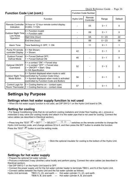
Function Code List (cont.)<br />
Function Code Number<br />
Quick Reference Guide - Page 26<br />
Function<br />
Hydro Unit<br />
Remote<br />
Controller<br />
Range<br />
Default<br />
Remote Controller<br />
Indication<br />
24 hour or 12 hour remote control display.<br />
0=24hr; 1=12hr<br />
- 05 0 ~ 1 0<br />
Outdoor Night Time<br />
Low Noise<br />
Operation<br />
0 = Function invalid<br />
1 = Function valid<br />
- 09 0 ~ 1 0<br />
Start time (hour) - 0A 0 ~ 23 22<br />
End time (hour) - 0B 0 ~ 23 06<br />
Alarm Tone Tone Switching 0: OFF, 1: ON 11 0 ~ 1 1<br />
Pump P2 remote<br />
controller Display<br />
0 = Not Shown;<br />
1 = Shown<br />
42 - 0 ~ 1 0<br />
Outdoor Forced<br />
Defrost Mode<br />
Optional ON/OFF<br />
Command<br />
Outdoor Night Time<br />
Mode Button<br />
Control Logic for<br />
Room Thermostat<br />
0 = Forced Defrost OFF;<br />
1 = Forced Defrost ON<br />
0 = a contact “ON” = Forced stop<br />
1 = b contact “OFF” = Forced stop<br />
2 = ON/OFF = Start / Stop<br />
3= HA Specification<br />
0 = Symbol displayed when mode is valid<br />
(controlled by Function Code Only);<br />
1 = Symbol displayed when mode is activated<br />
(controlled by Function Code and Button)<br />
0 = Cooling thermo on – contact open;<br />
1 = Cooling thermo on – contact close<br />
46 - 0 ~ 1 0<br />
52 - 0 ~ 3 0<br />
56 - 0 ~ 1 0<br />
57 - 0 ~ 1 0<br />
Settings by Purpose<br />
Settings when hot water supply function is not used<br />
• When the hot water supply function is not used, set DIP SW12-1 on the Hydro Unit board to ON.<br />
Setting for cooling<br />
• For Space Conditioning Units that do not perform cooling (radiators and Under floor heating, etc.), procure a<br />
motorized 2-way valve (for cooling) locally and attach it to the water pipe that is not used for cooling. Connect the<br />
valve cables (as described in Electrical section).<br />
• Press long the TEST + SET + SELECT switches on the remote controller to change the<br />
Hydro Unit function code, and change address 02 to 0, and then press the SET button to enable the function.<br />
Press the TEST<br />
button to exit the setting mode.<br />
• Stick the optional insulator for cooling to the bottom of the Hydro Unit.<br />
Settings for hot water supply<br />
• Prepare the optional hot water cylinder.<br />
• Procure a motorized 3-way (diverter) valve locally and perform piping. Connect the valve cables (as described in<br />
Electrical section).<br />
• Set DIP SW12-1 on the Hydro Unit board to OFF.<br />
• Connect the power supply unit for the hot water cylinder heater to terminals TB03 L and N of the Hydro Unit.<br />
• Connect cables between the Hydro Unit and the hot water cylinder as follows:<br />
Hydro Unit terminals TB03 (1), (2), and earth — Hot water cylinder (1), (2), and earth<br />
TB06 A, B, and earth — Hot water cylinder A, B, and earth