
You also want an ePaper? Increase the reach of your titles
YUMPU automatically turns print PDFs into web optimized ePapers that Google loves.
Quick Reference Guide - Page 27<br />
Settings by Purpose (cont)<br />
Settings for 2-zone temperature control<br />
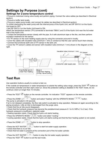
• Procure a motorized mixing valve locally and perform piping. Connect the valve cables (as described in Electrical<br />
section).<br />
• Procure a buffer tank locally.<br />
• Procure a water pump locally, and connect its cables (as described in Electrical section).<br />
To inhibit interlocking the water pump with the internal pump of the Hydro Unit, set DIP SW10-3 on the Hydro<br />
Unit board to OFF.<br />
• Set DIP SW12-3 on the Hydro Unit board to ON.<br />
Attach the temperature sensor (TFI) connected to terminals TB06 C and D of the Hydro Unit near the hot water<br />
inlet of the Hydro Unit.<br />
• Contact the temperature sensor closely with the pipe, fix it with aluminium tape or the like, and then perform<br />
insulation treatment for the sensor.<br />
• Fix TFI sensor on the room heating supply pipe by using the connector procured in locally.<br />
• Cover the cables with insulation tube (minimum 1 mm) or conduit so that the user cannot touch them directly.<br />
• Connect the functional earth wire of TFI sensor in the tank unit.<br />
• Cover the TFI sensor's cables and sensor with insulation tube (minimum 1 mm) shown in the diagram on the<br />
right.<br />
Test Run<br />
Use operation buttons usually to conduct a test run.<br />
If the outside air temperature or water temperature is outside the setting value range, press the TEST button on<br />
the remote controller and then start a test run. Since the protection setting is disabled in the TEST mode, do not<br />
continue a test run longer than 10 minutes.<br />
• Press the TEST<br />
button on the remote controller. An indication “TEST” appears on the remote controller.<br />
• Press the ZONE1, 2 button and select “heating” with the OPERATE MODE button.<br />
The pump is activated in 30 seconds.<br />
If air is not released completely, the flow rate switch is activated to stop operation. Release air again according to the<br />
piping procedure. Little air bite is discharged from the purge valve.<br />
• Check that the air bite sound disappears.<br />
• Check that the hydraulic pressure has become the predetermined pressure 0.1 to 0.2 MPa (1 to 2 bar). If the<br />
hydraulic pressure is insufficient, replenish water.<br />
• Heating operation starts. Check that the hydro unit starts heating.<br />
• Press the OPERATE MODE button and select “cooling.”<br />
• Cooling operation starts. Check that the hydro unit starts cooling and that the floor heating system is not cooled.<br />
• Press the ZONE1, 2<br />
button to stop operation.<br />
• Press the HOT WATER button to start hot water supply operation.<br />
• Check that there is no air bite.<br />
• Check that hot water is present at the connection port of the hot water cylinder.<br />
• Press the HOT WATER<br />
• Press the TEST<br />
button to stop the hot water supply operation.<br />
button to exit the test mode.