Chapter 7. Dislocations and Strengthening Mechanisms
Chapter 7. Dislocations and Strengthening Mechanisms
Chapter 7. Dislocations and Strengthening Mechanisms

You also want an ePaper? Increase the reach of your titles
YUMPU automatically turns print PDFs into web optimized ePapers that Google loves.
<strong>Chapter</strong> <strong>7.</strong><br />
<strong>Dislocations</strong> <strong>and</strong> <strong>Strengthening</strong> <strong>Mechanisms</strong><br />
<strong>7.</strong>1 Introduction<br />
With the knowledge of the nature of dislocations <strong>and</strong> the role they play in the plastic deformation<br />
process, we are able to underst<strong>and</strong> the underlying mechanisms of the techniques that are used to<br />
strengthen <strong>and</strong> harden metals <strong>and</strong> their alloys.<br />
On a microscopic scale, plastic deformation corresponds to the net movement of large numbers of<br />
atoms in response to an applied stress. During this process, interatomic bonds<br />
must be ruptured <strong>and</strong> then reformed. In crystalline solids, plastic deformation<br />
most often involves the motion of dislocations, linear crystalline defects that<br />
were discussed in chapter 4.<br />
This motion is called slip. Thus, the strength (resistance to deformation) can be<br />
improved by putting obstacles to slip.<br />
DISLOCATIONS AND PLASTIC DEFORMATION<br />
Early studies led computed theoretical strengths of perfect crystals, which were<br />
many times greater than those actually measured.<br />
During 1930s, theories introduced explained this difference in mechanical<br />
strengths by a type of linear defects called a dislocation.<br />
In 1950s, the existence of such dislocation defects was established by direct<br />
observation with electron microscope.<br />
<strong>7.</strong>2 Basic Concepts<br />
Edge <strong>and</strong> screw are the two fundamental dislocation types. See figures. Many dislocations in<br />
crystalline materials have both edge <strong>and</strong> screw components; mixed dislocations.<br />
Plastic deformation corresponds to the deformation of large number of dislocations. An edge<br />
dislocation moves in response to a shear stress applied in the direction perpendicular to its line; see<br />
figure.<br />
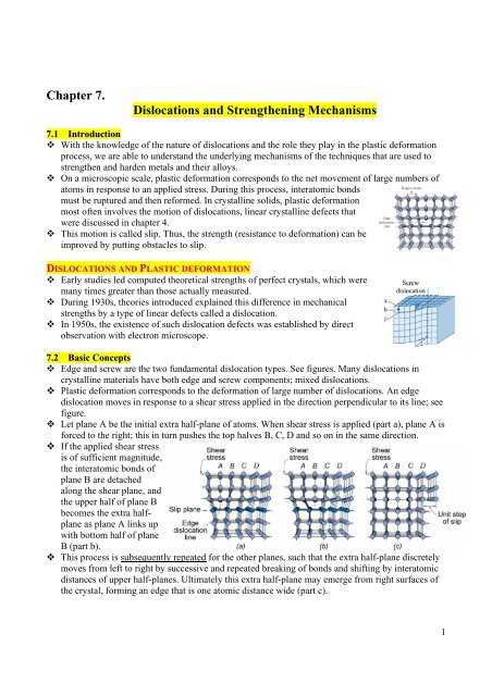
Let plane A be the initial extra half-plane of atoms. When shear stress is applied (part a), plane A is<br />
forced to the right; this in turn pushes the top halves B, C, D <strong>and</strong> so on in the same direction.<br />
If the applied shear stress<br />
is of sufficient magnitude,<br />
the interatomic bonds of<br />
plane B are detached<br />
along the shear plane, <strong>and</strong><br />
the upper half of plane B<br />
becomes the extra halfplane<br />
as plane A links up<br />
with bottom half of plane<br />
B (part b).<br />
This process is subsequently repeated for the other planes, such that the extra half-plane discretely<br />
moves from left to right by successive <strong>and</strong> repeated breaking of bonds <strong>and</strong> shifting by interatomic<br />
distances of upper half-planes. Ultimately this extra half-plane may emerge from right surfaces of<br />
the crystal, forming an edge that is one atomic distance wide (part c).<br />
1
The process by which plastic deformation is produced by dislocation is termed slip, the<br />
crystallographic plane along which the dislocation line crosses is the slip plane (see figure above).<br />
Dislocation motion is analogous to the mode of locomotion employed by a caterpillar. The<br />
caterpillar forms a hump near its posterior end by pulling in its last pair of legs a unit leg distance.<br />
The hump is propelled forward by repeated lifting of leg pairs. When the hump reaches the anterior<br />
end, the entire caterpillar<br />
has moved forward by the<br />
leg separation distance.<br />
This motion of hump<br />
corresponds to the motion<br />
of extra half-plane of<br />
atoms.<br />
Macroscopic plastic deformation simply corresponds to permanent deformation that results from<br />
the movement of dislocations, or slips, in response to shear stress (see figure). Part (a) shows an<br />
edge dislocation where the dislocation line moves<br />
parallel in the direction of the applied shear. Part (b)<br />
shows a screw dislocation where the dislocation line<br />
motion is perpendicular to the stress direction. However,<br />
the net plastic deformation for the motion of both<br />
dislocation types is the same.<br />
The direction of motion of the mixed dislocation line is<br />
neither perpendicular nor parallel to the applied stress,<br />
but lies somewhat in between.<br />
All metals <strong>and</strong> alloys contain some dislocations that were<br />
introduced during solidification, during plastic<br />
deformation, <strong>and</strong> as a consequence of thermal stresses<br />
that result from rapid cooling.<br />
Dislocation density in a material is expressed as the total dislocation length per unit volume, or<br />
equivalently, the number of dislocations that intersect a unit area of a r<strong>and</strong>om section. The units of<br />
dislocation density are mm of dislocation /mm^3 or just 1/mm^2.<br />
Dislocation densities as low as 10 3 / mm 2 are typically found in carefully solidified metal crystals.<br />
For heavily deformed metals, the density may run as high as 10 9 – 10 10 /mm 2 . Heat treating a<br />
deformed metal specimen can diminish the density to on the order of 10 5 – 10 6 /mm 2 .<br />
For ceramic materials, dislocation density is between 10^2 – 10^4 /mm2. For silicon single<br />
crystals (used in IC) the value lies between 0.1 – 1 /mm^2.<br />
2
<strong>7.</strong>3 Characteristics of <strong>Dislocations</strong><br />
Strain fields (important dislocation characteristic) exist<br />
around dislocations which are influential in determining the<br />
mobility of the dislocations, as well as their ability to<br />
multiply.<br />
When metals are plastically deformed, some fraction of the<br />
deformation energy (approx. 5%) is retained internally; the<br />
remainder is dissipated as heat. The major portion of this<br />
stored energy is strain energy associated with dislocations.<br />
Consider the edge dislocation shown in the figure. Some<br />
atomic lattice distortion exists around the dislocation line. Consequently, there are regions in which<br />
compressive, tensile, <strong>and</strong> shear lattice strains are imposed in the neighboring atoms.<br />
Atoms immediately above <strong>and</strong> adjacent to the dislocation line are squeezed together; may be<br />
thought of as experiencing a compressive strain relative to atoms positioned far in the perfect<br />
crystal.<br />
Directly below the half-plane, lattice atoms sustain an imposed tensile strain<br />
Shear strains also exist in the vicinity of the edge dislocation. However, for a screw dislocation,<br />
lattice strains are pure shear only.<br />
Lattice distortions may be considered as<br />
strain fields that radiate from the dislocation<br />
line. The strains extend into the surrounding<br />
atoms with magnitude decreasing with radial<br />
distance from dislocation.<br />
Strain fields surrounding two (or more)<br />
adjacent dislocations may interact such that<br />
forces are imposed on each dislocation by<br />
the combined interactions of all its<br />
neighboring dislocations.<br />
For example, consider two edge dislocations<br />
that have the same sign <strong>and</strong> the same slip<br />
plane (part a of the figure). The strain field<br />
interaction is such there exists between these<br />
two isolated dislocations a mutual repulsive<br />
force that tends to move them apart.<br />
Part (b) shows that two edge dislocations with the same slip plane but opposite sign will be<br />
attracted to one another <strong>and</strong> dislocation annihilation will occur when they meet. The two extra halfplanes<br />
of atoms will align <strong>and</strong> become a complete plane.<br />
Dislocation interactions are possible between edge, screw,, <strong>and</strong>/or mixed dislocations. Resulting<br />
stain field are important in the strengthening mechanisms of metals.<br />
During plastic deformation, the number of dislocations increases dramatically. Dislocation density<br />
of highly deformed may be as high as 10^10 /mm^2. One important source of such increase is<br />
existing dislocations which multiply. Also, grain boundaries as well as internal defects <strong>and</strong> surface<br />
irregularities (scratches <strong>and</strong> nicks - stress concentrations) may serve as dislocation formation sites<br />
during deformation.<br />
3
<strong>7.</strong>4 Slip Systems<br />
<strong>Dislocations</strong> do not move with the same degree of ease on all crystallographic planes of atoms <strong>and</strong><br />
in all crystallographic directions.<br />
Ordinarily there is a preferred plane <strong>and</strong> in that plane there are specific directions along which<br />
dislocation motion occurs. This plane is called the slip plane <strong>and</strong> the direction of movement is<br />
called the slip direction. The combination of the slip plane <strong>and</strong> the slip direction is called the slip<br />
system.<br />
The slip system depends on the crystal structure of the metal <strong>and</strong> is such that the atomic distortion<br />
(which accompanies the motion of a dislocation) is a minimum.<br />
For a particular crystal structure, the slip plane is the plane that has the most dense atomic<br />
packing; the greatest planar density. Also, the slip direction corresponds to the direction (in the slip<br />
plane) that is most closely packed with atoms; the highest linear density. (see section 3.11). How<br />
do we explain this<br />
Since the distance between atoms is shorter than the average, the distance perpendicular to the<br />
plane has to be longer than average. Being relatively far apart, the atoms can move more easily<br />
with respect to the atoms of the adjacent plane.<br />
Example: consider the FCC crystal structure, part<br />
(a) shows a unit cell. There is a set of planes, the<br />
{111} family, all of which are closely packed. A<br />
{111}-type plane is indicated in the unit cell (part b).<br />
Slip occurs along -type direction within the<br />
{111} planes as indicated in the figure. Hence,<br />
{111} represents the slip plane <strong>and</strong> direction<br />
combination, or the slip system for FCC.<br />
Several slip systems may exist for a particular crystal structure, the number of independent slip<br />
systems represents the different possible combinations of slip planes <strong>and</strong> directions. For FCC, there<br />
are 12 slip systems: 4 unique {111} planes <strong>and</strong> (within each plane) 3 independent <br />
directions.<br />
Table below list the possible slip systems for FCC, BCC, <strong>and</strong> HCP crystal structures. For BCC <strong>and</strong><br />
HCP, slip is possible on more than one family of planes which are operable at elevated<br />
temperatures.<br />
Metals with FCC <strong>and</strong> BCC crystal structures have a relatively large number of slip systems (at least<br />
12). These metals are quite ductile because extensive plastic deformation is possible along the<br />
various systems. Conversely, HCP metals having few slip systems are normally quit brittle.<br />
4
<strong>7.</strong>5 Slip in Single Crystals<br />
As discussed previously, edge, screw, <strong>and</strong> mixed dislocations move in response to shear stresses<br />
applied along a slip plane <strong>and</strong> in a slip direction.<br />
Also, as noted in section 6.2, even though an applied stress may be pure tensile<br />
(or compressive), shear components exist at all but parallel or perpendicular<br />
alignments to the stress direction. These shear components are called resolved<br />
shear stresses, <strong>and</strong> their magnitudes depend not only on the applied stress, but<br />
also on the orientation of the both the slip plane <strong>and</strong> direction within that plane.<br />
Let (see figure)<br />
φ = angle between applied stress direction <strong>and</strong> the normal to slip plane.<br />
λ = angle between applied stress direction <strong>and</strong> slip direction.<br />
It can be shown that the resolved shear stress is<br />
τ R = σ cosφ<br />
cos λ<br />
(<strong>7.</strong>1)<br />
where σ is the applied stress.<br />
o<br />
In general, φ + λ ≠ 90 . Tensile stress, slip direction, <strong>and</strong> the slip-plane normal<br />
can not lie in the same plane.<br />
A metal single crystal has a number of different slip systems that are capable of<br />
operating. Each with different resolved shear stress (orientations differ). However, one slip system<br />
is generally oriented most favorably; has the largest resolved shear stress:<br />
τ = (<strong>7.</strong>2)<br />
R ) max σ (cosφ<br />
cosλ<br />
) max<br />
In response to an applied tensile (or compressive) stress, slip in a single crystal specimen starts on<br />
the most favorably oriented slip system when the resolved shear stress reaches some critical value,<br />
called the critical resolved shear stress λ crss ; it represents the minimum shear stress required to<br />
initiate slip <strong>and</strong> hence when yielding occurs.<br />
Therefore, the single crystal plastically deforms or yields when τ R ) max = τ crss <strong>and</strong> the magnitude<br />
of the applied stress required to initiate yielding (yield strength) is<br />
τ<br />
crss<br />
σ y = (<strong>7.</strong>3)<br />
(cosφ<br />
cos λ ) max<br />
The minimum stress necessary to introduce yielding occurs when a single crystal is oriented such<br />
o<br />
that φ = λ = 45 , under these conditions<br />
σ y = 2 τ crss<br />
(<strong>7.</strong>4)<br />
For a single-crystal specimen that is stressed in tension, deformation will be as<br />
shown, where slip occurs along a number of equivalent <strong>and</strong> most favorably<br />
oriented planes <strong>and</strong> directions at various positions along the specimen length.<br />
This slip deformation forms as small steps on the surface of the single crystal<br />
that are parallel to one another <strong>and</strong> loop around the circumference of the<br />
specimen as indicated. Each step results from the movement of a large<br />
number of dislocations along the same slip plane.<br />
5
On the surface of a polished single crystal specimen, these steps appear as lines, which<br />
are called slip lines. A zinc single crystal that has been plastically deformed to the degree<br />
that theses slip markings are noticeable as shown.<br />
As extension of a single crystal continues, both the number of slip lines <strong>and</strong> slip step<br />
width will increase.<br />
See Example <strong>7.</strong>1<br />
Applied tensile stress along [010] direction, a) compute τ R along a (110) plane <strong>and</strong> in a [1<br />
[ 1 11 ] direction when a tensile stress 52 MPa is applied, b) if τ crss =30 MPa on this<br />
slip system, calculate magnitude of the applied tensile needed to initiate yielding.<br />
φ = 45<br />
o<br />
,<br />
λ = tan<br />
−1<br />
( a<br />
2 / a ) = 54.7<br />
a) τ R = σ cosφ<br />
cosλ<br />
= ( 52 )(cos45 )(cos54.7 ) = 21.3 MPa<br />
τ crss<br />
30 MPa<br />
b) σ y = =<br />
= 73.4 MPa<br />
o<br />
o<br />
(cosφ<br />
cos λ ) (cos 45 )(cos54.7 )<br />
max<br />
o<br />
o<br />
o<br />
<strong>7.</strong>6 Plastic Deformation of Polycrystalline Materials<br />
Deformation <strong>and</strong> slip here is more complex. Because of the r<strong>and</strong>om<br />
crystallographic orientations of the numerous grains, the direction of slip<br />
varies from one grain to another. For each, dislocation motion occurs<br />
along the slip system that has the most favorable orientation. See a<br />
photomicrograph of a polycrystalline copper specimen that has been<br />
polished <strong>and</strong> then deformed. Slip lines (microscopic ledge-similar to steps<br />
in single crystal) are visible. It appears that two slip systems operated for<br />
most of the grains; two sets of parallel yet intersecting sets of lines.<br />
During deformation, grain boundaries usually do not come apart or open<br />
up. As a consequence, each individual grain is constrained (to some<br />
degree) in the shape it may assume by its neighboring grains (see figure).<br />
Before deformation the grains have approximately the same dimension in<br />
all directions. After deformation, grains become elongated along the<br />
direction in which the specimen was extended.<br />
300 µ m<br />
6
<strong>7.</strong>7 Deformation By Twinning (not covered)<br />
MECHANISMS OF STRENGTHENING IN MATERIALS<br />
Often as materials engineers we need to design alloys having high strengths yet some ductility<br />
<strong>and</strong> toughness. Ordinarily, ductility is sacrificed when alloy is strengthened. Several hardening<br />
techniques are available.<br />
Because macroscopic plastic deformation corresponds to the motion of large numbers of<br />
dislocations, the ability of a metal to plastically deform depends on the ability of dislocations to<br />
move.<br />
So, by reducing the mobility of dislocations, the mechanical strength may be enhanced; need<br />
greater mechanical forces to initiate plastic deformation. In contrast, the more unconstrained the<br />
dislocation motion, the greater is the ability with which a metal may deform, <strong>and</strong> the softer <strong>and</strong><br />
weaker it becomes.<br />
All strengthening techniques rely on the principle: “Restricting or hindering dislocation motion<br />
renders a material harder <strong>and</strong> stronger”.<br />
The discussion below is confined to strengthening mechanisms for single-phase metals: grain size<br />
reduction, solid-solution alloying, <strong>and</strong> strain hardening. Deformation <strong>and</strong> strengthening of<br />
multiphase alloys are more complicated.<br />
<strong>7.</strong>8 <strong>Strengthening</strong> By Grain Size Reduction<br />
The size of grains in a polycrystalline influences the<br />
mechanical properties. Adjacent grains normally<br />
have different crystallographic orientation <strong>and</strong>, of<br />
course, a common grain boundary (see figure).<br />
During plastic deformation, dislocation motion<br />
(slip) must take place across this common boundary<br />
(from grain A to grain B). The grain boundary acts<br />
as a barrier to dislocation motion for two reasons:<br />
7
Since the two grains are of different orientations, a dislocation passing into grain B will have to<br />
change its direction of motion; this becomes more difficult as crystallographic misorientation<br />
increases.<br />
The atomic disorder within a grain boundary region will result in a discontinuity of slip planes<br />
from one grain into the other.<br />
It should be mentioned that for high-angle grain boundaries, dislocations may not cross grain<br />
boundaries during deformation; rather, a stress concentration ahead of a slip plane in one grain may<br />
activate sources of new dislocations in an adjacent grain.<br />
A fine-grained material (one that has small grains) is harder <strong>and</strong> stronger than one that is coarse<br />
grained. The former has a greater total grain boundary area to impede dislocation motion. For<br />
many materials, the yield strength σ varies with grain size according to Hall-Petch equation:<br />
y<br />
o<br />
y<br />
y<br />
−1 / 2<br />
σ = σ + k d<br />
(<strong>7.</strong>5)<br />
Where d = average grain diameter, σ o <strong>and</strong> k y are<br />
constants for a given material.<br />
Equation (<strong>7.</strong>5) is not valid for both very large (coarse)<br />
grain <strong>and</strong> extremely fine grain polycrystalline materials.<br />
The figure shows the influence of grain size on the<br />
yield strength of a 70 Cu – 30 Zn brass alloy. Note that<br />
the grain diameter increases from right to left <strong>and</strong> is not<br />
linear.<br />
Grain size may be regulated by the rate of solidification<br />
from the liquid phase, <strong>and</strong> also by plastic deformation<br />
followed by an appropriate heat treatment.<br />
Grain size reduction improves not only strength, but<br />
also the toughness of many alloys.<br />
Small-angle grain boundaries (4.6) are not effective in<br />
interfering wit slip process because the slight<br />
crystallographic misalignement across the boundary. However, the twin boundary will effectively<br />
block slip <strong>and</strong> increase the strength of the material.<br />
8
<strong>7.</strong>9 Solid-Solution <strong>Strengthening</strong> (see CD)<br />
Alloying metals with impurity atoms (substitutional or interstitial) into solid solution (section 4.3)<br />
is another technique to strengthen <strong>and</strong> harden metals. This is called solid-solution strengthening.<br />
High-purity metals are almost always softer <strong>and</strong> weaker than alloys composed of the same base<br />
metal. Increasing the concentration of impurity results in an attendant increase in tensile <strong>and</strong> yield<br />
strengths. Figure shown indicates variation of tensile strength, yield strength, <strong>and</strong> ductility (%EL)<br />
with nickel content for copper-nickel alloy.<br />
Alloys are stronger than pure metals because impurity<br />
atoms that go into the solid solution ordinarily impose<br />
lattice strains on the surrounding host atoms. Lattice<br />
strain field interactions between dislocations <strong>and</strong> these<br />
impurity atoms result, <strong>and</strong> consequently dislocation<br />
movement is restricted.<br />
An impurity atom that is smaller than a host atom for<br />
which it substitutes exerts tensile strains on the<br />
surrounding crystal lattice (part a).<br />
(c)<br />
Conversely, a larger substitutional atom imposes<br />
(d)<br />
compressive strains in its vicinity (part c).<br />
These solute atoms tend wonder <strong>and</strong> diffuse through the lattice <strong>and</strong> reach around dislocations so to<br />
reduce the overall strain energy (cancel some of the strain in the lattice surrounding a dislocation).<br />
9
To accomplish this, a smaller impurity atom is located where its tensile strain will partially cancel<br />
some of the dislocation’s compressive strain; adjacent to the dislocation line <strong>and</strong> above the slip<br />
plane (see part b). A larger impurity atom wonders <strong>and</strong> diffuses through the lattice where its<br />
compressive strain will partially cancel some of the dislocation’s tensile strain; below the<br />
dislocation line (see part d).<br />
An interstitial impurity atom (imposes compressive stains in its vicinity) wonders <strong>and</strong> diffuses<br />
through the lattice where its compressive strain will partially cancel some of the dislocation’s<br />
tensile strain; just below the dislocation line<br />
For both cases, the resistance to slip is greater when impurity atoms are present. Also, the same<br />
lattice strain interactions will exist between impurity atoms <strong>and</strong> dislocations that are in motion<br />
during plastic deformation. Thus, a greater applied stress is necessary to first initiate <strong>and</strong> then<br />
continue plastic deformation for solid-solution alloys, as opposed to pure metals; thus,<br />
enhancement of strength <strong>and</strong> hardness.<br />
<strong>7.</strong>10 Strain Hardening<br />
Strain hardening is the phenomenon whereby a ductile metal becomes harder <strong>and</strong> stronger as it is<br />
plastically deformed. Sometimes it is called work hardening or cold working (because it is<br />
deformed at cold temperature relative to the absolute melting temperature of the metal).<br />
May express the degree of plastic deformation as percent cold work rather than strain. Percent cold<br />
work (%CW) is defined as:<br />
⎛ Ao<br />
− Ad<br />
⎞<br />
% CW = ⎜ X 100<br />
A<br />
⎟<br />
(<strong>7.</strong>6)<br />
⎝ 0 ⎠<br />
Where A o = original area of the cross section that experiences deformation.<br />
A d = area after deformation.<br />
Figure shown indicates for 1049 steel, brass, <strong>and</strong> copper: (a) the increase in yield strength, (b) the<br />
increase in tensile strength, <strong>and</strong> (c) the decrease in ductility (%EL) with increasing %CW.<br />
The price paid for the enhancement of strength <strong>and</strong> hardness is a reduction in the ductility (%EL)<br />
of the metal as %CW increases.<br />
10
Strain hardening is demonstrated in a stress-strain<br />
diagram shown (section 6.8) – see figure repeated.<br />
It can be explained: the dislocation density in a metal<br />
increases with cold work (deformation) due to dislocation<br />
multiplication or formation of new dislocations. Thus, the<br />
average distance of separation between dislocations<br />
decreases-dislocation are positioned closer together. One<br />
the average, dislocation-dislocation strain interactions are<br />
repulsive. The net result is that the motion of a<br />
dislocation is hindered by the presence of other<br />
dislocations. As the dislocation density increases,<br />
resistance to dislocation motion becomes more<br />
pronounced. Thus, stress needed to deform a metal<br />
increases with increasing cold work.<br />
Figure shown demonstrates the influence of cold work on the<br />
stress-strain behavior for low-carbon steel.<br />
Strain hardening is often utilized commercially to enhance the<br />
mechanical properties of metals during fabrication procedures.<br />
The effects of strain hardening may be removed by annealing heat<br />
treatment (chapter 11).<br />
Stress<br />
See Example <strong>7.</strong>2<br />
The above three mechanisms may be used to strengthen <strong>and</strong><br />
harden single-phase metal alloys. Of course they may be used in<br />
conjunction with one another, for example, a solid-solution<br />
strengthened alloy may also be strain hardened.<br />
% cold work<br />
Strain<br />
RECOVERY, RECRYSTALIZATION, AND GRAIN GROWTH<br />
So far, plastically deforming a polycrystalline metal specimen at temperatures that are low relative<br />
to its absolute melting temperature produces microstructural <strong>and</strong> property changes that include:<br />
1) A change in grain shape (<strong>7.</strong>6),<br />
2) Strain hardening (<strong>7.</strong>10), <strong>and</strong><br />
3) Increase in dislocation density (<strong>7.</strong>3).<br />
Some fraction of the energy spent in deformation is stored as strain energy, which associated with<br />
tensile, compressive, <strong>and</strong> shear zones around the newly created dislocations (<strong>7.</strong>3). Other properties<br />
such as electrical conductivity <strong>and</strong> corrosion resistance may be modified as a consequence of<br />
plastic deformation.<br />
These properties <strong>and</strong> structures may revert back to the precold-worked states by appropriate heat<br />
treatment (called annealing treatment: heating to desired temp. , holding at that temp for a period<br />
of time (soaking), air or furnace cooling to room temp. This restoration results from two different<br />
processes that occur at elevated temperatures: recovery <strong>and</strong> recrystallizations which may be<br />
followed by grain growth.<br />
11
<strong>7.</strong>11 Recovery<br />
With no applied external stress, heating <strong>and</strong> holding at elevated temperature increases atomic<br />
diffusion enhances dislocation motion relieves some of the stored internal strain energy.<br />
There is some reduction in the number of dislocations, <strong>and</strong> dislocations with low internal strain<br />
energy are produced.<br />
Also, physical properties such as electrical <strong>and</strong> thermal conductivities <strong>and</strong> the like are recovered to<br />
the values existed before cold working.<br />
<strong>7.</strong>12 Recrystallization<br />
Even after recovery is complete, the grains are still in relatively high strain energy state.<br />
Recrystallization is the formation of a new set of strain-free <strong>and</strong> equiaxed grains (approx. equal<br />
dims. in all dirs.) that have low dislocation densities <strong>and</strong> are characteristic of the precold-worked<br />
condition.<br />
The difference in internal energy between the strain <strong>and</strong> the unstrained material is the driving force<br />
to produce this new grain structure.<br />
The new grains form as very small nuclei <strong>and</strong> grow until they completely consume the parent<br />
material, processes that involve short-range diffusion (Temp. <strong>and</strong> Time are important parameters.)<br />
The photomicrographs below show several stages of recrystallization <strong>and</strong> grain growth of brass:<br />
a) Cold-worked grain structure (33%CW) (70X).<br />
b) Initial stage of recrystallization after 3s at 580 o C, the very small grains are those that have recrystallized.<br />
c) Partial replacement of cold-worked grains by recrystallized ones after 4s at 580 o C.<br />
d) Complete recrystalization after 8s at 580 o C. All called-worked crystals are consumed.<br />
e) Grain growth after 15 min. at 580 o C. f) Grain growth after 10 min. at 700 o C.<br />
0.6 mm<br />
0.6 mm 0.6 mm<br />
a) 33% cold<br />
worked<br />
brass<br />
0.6 mm<br />
b) New crystals<br />
nucleate after<br />
3 sec. at 580C.<br />
0.6 mm<br />
c)After 4<br />
seconds<br />
d)After 8<br />
seconds<br />
e)After 15 min<br />
at 580 C<br />
12
Above figures show that recrystallization depends on time. Next figure shows that recrystallization<br />
also depends on temperature: the influence of annealing temperature on the tensile strength <strong>and</strong><br />
ductility of a brass alloy (heat treatment for 1 h). Grain size as a function of annealing temperature<br />
is indicated. Grain structures during recovery, recrystallization, <strong>and</strong> grain growth stages are shown.<br />
Recrystallization behavior is sometimes specified in terms of a recrystallization temperature.<br />
Recrystallization temperature: is that at which the recrystallization is complete in one hour;<br />
grains in the cold-worked microstructure begins to transform into new, equiaxed, <strong>and</strong> dislocationfree<br />
grains. Recrystallization temperature of brass alloy shown above is about 450 o C.<br />
Typically, it is 1/3 to 1/2 of the absolute melting temperature of a metal or alloy <strong>and</strong> depends on<br />
many factor including amount of prior cold work <strong>and</strong> purity of alloy. Increasing %CW, enhances<br />
rate of recrystallization, <strong>and</strong> lowers recrystallization temperature.<br />
There exists some critical value of %CW below which recrystallization cannot be achieved. (2% -<br />
20%). Next figure shows the variation of recrystallization temperature with %CW for iron. Note<br />
for deformation less than the critical deformation (about %CW), recrystallization will not occur.<br />
13
Recrystallization precedes more rapidly in pure metals than alloys. For pure metals,<br />
recrystallization temperature is normally (0.3 T m ) where T m is the absolute melting temperature.<br />
For some commercial alloys it may run as high as (0.7 T m ). See table below for recrystallization<br />
<strong>and</strong> melting temperatures for a number metals <strong>and</strong> alloys.<br />
Design Example <strong>7.</strong>1<br />
Cylindrical rod of noncold-worked brass having initial diameter = 6.4 mm.<br />
Need to be cold worked by drawing such that the cross-sectional area is reduced.<br />
Require to have cold-worked yield strength of at least 345 MPa <strong>and</strong> ductility in excess of 20% EL, <strong>and</strong><br />
a final diameter of 5.1 mm is necessary. Describe the procedure.<br />
Solution:<br />
From di = 6.4 mm to do = 5.1 mm, the %CW<br />
2<br />
2<br />
⎛ Ao<br />
− A ⎞<br />
d π(6.4/<br />
2) − π(5.1/<br />
2)<br />
% CW =<br />
⎜ X 100 =<br />
X100<br />
= 36.5% CW<br />
2<br />
A<br />
⎟<br />
⎝ 0 ⎠<br />
π(6.4/<br />
2)<br />
From Figs. on page 10 σ<br />
y<br />
= 410 MPa <strong>and</strong> ductility = 8% EL. So strength is satisfactory but is<br />
too low.<br />
Try another processing with partial diameter reduction, followed by a recrystallization heat treatment<br />
in which the effects of the cold work are nullified.<br />
The required yield strength, ductility, <strong>and</strong> diameter are achieved through a second drawing step.<br />
From Fig.(a) 20% CW gives σ<br />
y<br />
= 345 MPa . But part (c) shows that greater than 20% EL are<br />
possible for deformation of 23% CW or less.<br />
Thus during the final drawing operation, deformation must be between 20%CW <strong>and</strong> 23%CW.<br />
Take the average 21.5%CW, <strong>and</strong> then calculate the final diameter for the first drawing do', which<br />
becomes the original for the second drawing. So,<br />
' 2<br />
π ( d<br />
o<br />
/ 2) − π (5.1/ 2)<br />
21.5%<br />
CW =<br />
' 2<br />
π ( d / 2)<br />
o<br />
2<br />
X100<br />
Or<br />
'<br />
d o<br />
= 5. 8 mm<br />
14
<strong>7.</strong>13 Grain Growth<br />
After recrystallization is complete, the strain-free grains will<br />
continue to grow if the metal specimen is held at the elevated<br />
temperature. See part (e) of figure above: grain growth after 15 min<br />
at 580 o C. This phenomenon is called grain growth. Grain growth<br />
does not have to be preceded by recovery <strong>and</strong> recrystallization.<br />
An energy is associated with grain boundaries. As grains increase in<br />
size, the total boundary area decreases, yielding an attendant<br />
reduction in the total energy which is the driving force for grain<br />
growth. Big grains grow at the expense of the small ones that shrink.<br />
Thus the average grain size increases with time.<br />
The growth of grain size with temperature can occur in all<br />
polycrystalline materials. It occurs by migration of atoms at grain<br />
boundaries by diffusion, thus grain growth is faster at higher<br />
temperatures. The directions of boundary movement <strong>and</strong> atomic<br />
motion are opposite to each other as shown in the figure.<br />
For many polycrystalline materials, the grain diameter d varies with<br />
time t according to the empirical relation:<br />
n<br />
n<br />
d − do<br />
= Kt<br />
(<strong>7.</strong>7)<br />
Where d = grain diameter at time t, d o = initial grain diameter at time t = 0.<br />
K = coefficient dependent on material <strong>and</strong> temperature T.<br />
n = constant equals to greater than 2.<br />
t = elapsed time.<br />
The dependence of grain size on time <strong>and</strong> temperature is demonstrated in the figure shown. A plot<br />
of the logarithm of grain size as a function of the logarithm of time for brass alloy at several<br />
temperatures. The curves are linear at<br />
lower temperature. Grain growth<br />
proceeds more rapidly as temperature<br />
increases; the curves are displaced<br />
upward to larger grain sizes. This is<br />
explained by enhancement of diffusion<br />
rate with rising temperature.<br />
15
Notes:<br />
1) Fabrication of metals: forming operations, casting, powder metallurgy & welding.<br />
2) Thermal processing of metals: Annealing processes, quenching, <strong>and</strong> tempering.<br />
3) Plastic deformation is usually achieved by forming operations, where some external stress is<br />
used with magnitude exceeding the<br />
yield strength of the material.<br />
Examples of forming techniques are:<br />
a) forging, b) rolling, c) extrusion,<br />
<strong>and</strong> d) drawing.<br />
4) When deformation is achieved at a<br />
temperature above that at which<br />
recrystallization occurs, the process<br />
is termed hot working, otherwise, it<br />
is termed cold working.<br />
16