Low power microcontroller based intelligent token number ... - IJET
Low power microcontroller based intelligent token number ... - IJET
Low power microcontroller based intelligent token number ... - IJET

Create successful ePaper yourself
Turn your PDF publications into a flip-book with our unique Google optimized e-Paper software.
IACSIT International Journal of Engineering and Technology, Vol.3, No.2, April 2011<br />
5) 53 Programmable I/O Lines<br />
64-lead TQFP and 64-pad QFN/MLF<br />
6) Reliability Qualification results show that the projected<br />
data retention failure rate is much less than 1 PPM over 20<br />
years at 85°C or 100 years at 25°C.<br />
B. Key button<br />
We have only used two key buttons. The first button<br />
increases the display <strong>number</strong> and the second button reset the<br />
program. The first button is connected to pin <strong>number</strong> PD2 of<br />
the <strong>microcontroller</strong> and the second button is connected to pin<br />
<strong>number</strong> PD3 of the same <strong>microcontroller</strong>. To prevent the<br />
debouncing and to balance the current we have used 320<br />
resistors <strong>microcontroller</strong> pin to ground.<br />
C. Display unit<br />
In our project we used seven segment displays. We have<br />
used two set of seven segment display. Operator display and<br />
customer display. There are three seven segment in each set.<br />
Seven segment displays contains seven LED bars. Seven<br />
segment display are available in two types, called, ’common<br />
cathode’ and ‘common anode’. In our project we used<br />
‘common cathode ‘type display. We used CMOS 4026B to<br />
control the seven segment display this system uses just two<br />
pins to control the display. The reset is used to reset the<br />
display to 0. The clock pin is then used to increment the digit<br />
up from 0. This means to display the digit ‘3’ it is necessary<br />
to reset and then pulse the clock line 4 times in reality this<br />
means that the display shows the digits 0-1-2-3, but as they<br />
are clocked extremely rapidly, the human eye cannot see<br />
changes and the <strong>number</strong> ‘3’ seems to appear immediately.<br />
This system can be expanded to three digits by adding a three<br />
4026B IC and a three seven segment display.<br />
<strong>microcontroller</strong> programming .We have done it in avr<br />
bascom compiler. We have already shown the input pin<br />
settings. We had to declare and initialize some variables<br />
(K,D,L,M,N,T)to control the program. The variable ‘K’<br />
represents the value of counter. Variable K will be<br />
incremented if pin PD2 is high. we have given a pulse in the<br />
pin <strong>number</strong> PD6-which is connected to the clock pin of<br />
4026.For each pulse the IC will increase a decimal <strong>number</strong> in<br />
display. After every increment, the value of K will be<br />
checked. If it goes to one thousand then it will be assigned to<br />
0. For any digit (less than 1000)it will make a <strong>number</strong> of three<br />
digit. (for example if K=9,the <strong>number</strong> will be 009).The first,<br />
second and third digit will be kept in variable M,N,L<br />
respectively. We have initialized D=1, at first the value of M<br />
will be moved to T. Then the <strong>number</strong> in T will be checked.<br />
The <strong>number</strong>s (which is found from T) respective data has<br />
been moved to the data array of the port A. After every<br />
increment it will wait for a little while. Then every time the<br />
value of D will be checked whether it is 3 or not.<br />
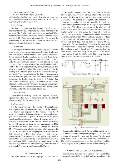
Fig. 2 .Circuit diagram of 5V <strong>power</strong> supply<br />
D. Sound module<br />
Sound module basically consists of a speaker. We used<br />
speaker for <strong>token</strong> <strong>number</strong> announcement. The IC LM741<br />
filters and amplifies the analog signal.<br />
E. Power supply<br />
For the proper working of the circuit a 5v DC supply is all<br />
that required. The <strong>microcontroller</strong> requires 5v for working.<br />
The display also requires 5v for working precisely. A<br />
<strong>microcontroller</strong> <strong>based</strong> system demands a <strong>power</strong> supply which<br />
provides a constant DC <strong>power</strong>. A transient on the <strong>power</strong><br />
supply could result in system failure. The <strong>power</strong> supply unit<br />
designed in this system is 5v DC and not affected by variation<br />
in the AC serving as input to the transformer. A 230v<br />
transformer is used with output voltage of 9v.Four<br />
IN4007diodes formed a bridge rectifier, which converts the<br />
AC to DC and satisfies the charging current demands of the<br />
filter capacitor. The DC voltage varies above and below an<br />
average value. This variation is called ripple voltage which is<br />
reduced to a minimum value by filter capacitors. Capacitors<br />
of capacitance 1000microfarads were chosen to reduce the<br />
ripple voltage and achieve a filtered voltage which resembles<br />
a smooth DC voltage as much as possible (fig.1).<br />
Fig . 3 . Proteus Simulation output<br />
For the value of D (accept D=3), we will increase it by 1.<br />
It will do the same taking the next digits. If D=3 then our<br />
program will regard D=1 and wait for input. Then for next<br />
every input, it will do the same, increasing the value of K.<br />
The whole program is shown in the flowchart (fig.4) and the<br />
circuit diagram of our proposed device is shown in (fig.3).<br />
IV. METHODOLOGY<br />
We have chosen the basic language, to work out in<br />
200<br />
V. MAKING THE DATA FILE FROM SOUND FILE<br />
For collecting data from voice signal we first recorded the<br />
distinct voice signals for every digit and then a matlab code is