HIGH-TEMPERATURE GEOTHERMAL WELL DESIGN - Orkustofnun
HIGH-TEMPERATURE GEOTHERMAL WELL DESIGN - Orkustofnun
HIGH-TEMPERATURE GEOTHERMAL WELL DESIGN - Orkustofnun

Create successful ePaper yourself
Turn your PDF publications into a flip-book with our unique Google optimized e-Paper software.
<strong>GEOTHERMAL</strong> TRAINING PROGRAMME Reports 2005<br />
<strong>Orkustofnun</strong>, Grensásvegur 9, Number 9<br />
IS-108 Reykjavík, Iceland<br />
<strong>HIGH</strong>-<strong>TEMPERATURE</strong> <strong>GEOTHERMAL</strong> <strong>WELL</strong> <strong>DESIGN</strong><br />
Hossein Hossein-Pourazad<br />
Renewable Energy Organization of Iran (SUNA)<br />
Yadegare Emam Highway, Poonake Bakhtari Ave., Shahrake Ghods,<br />
P.O. Box 14155-6398, Tehran<br />
IRAN<br />
hhosseinpourazad@yahoo.com<br />
ABSTRACT<br />
This paper presents methods which are used for determining the design conditions<br />
for high-temperature geothermal wells. Basic information, such as geological<br />
conditions and types of reservoirs, is presented. The emphasis is on casing design<br />
for high-temperature geothermal wells including casing loads such as collapse and<br />
burst pressures, determination of the minimum depth of casings, etc. For a “worst<br />
possible case” where no actual data is available, the boiling point curve is used.<br />
Collapse pressure is often what determines the casing wall thickness. A well<br />
simulation model can be a powerful tool for predicting the temperature and<br />
pressure along the well axis. The temperature and pressure for a flowing and a<br />
shut-in well comprises the primary basis for casing design.<br />
1. INTRODUCTION<br />
In designing high-temperature geothermal wells, many parameters must be considered. First are the<br />
geological aspects. High-temperature geothermal areas are mostly connected to volcanism in rift and<br />
subduction zones. The geothermal reservoirs formed are basically classified according to their<br />
temperature. The physical parameters, temperature and pressure within the reservoir, define the<br />
design criteria of geothermal wells. These are influenced by the heat source and permeability of the<br />
reservoir.<br />
Casing designing is a major part of geothermal well design. The casing programme is defined by the<br />
number of casing strings their diameters and lengths, and wall thickness. Casing wall thickness for<br />
deep casings is determined mainly by the collapse pressure which is exerted from the cement column<br />
during the cementing operation.<br />
There are several methods for determining the depth at which the casing shoe is set. “A rule of<br />
thumb” says that the minimum casing depth shall be one third of the total depth of the particular<br />
section of the well being drilled. The design procedures used in Iceland and New Zealand for<br />
determination of minimum casing depths are explained.<br />
111
Hossein-Pourazad 112<br />
Report 9<br />
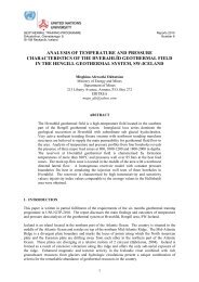
2. GEOLOGICAL CONDITIONS<br />
Generally, high-temperature geothermal areas are mostly connected to volcanism in rift and<br />
subduction zones. Intrusions and magma chambers serve as heat sources for each high-temperature<br />
geothermal system. The surrounding groundwater approaches the heat source, is heated up and a<br />
dynamic convection system is initiated which will last as long as the fundamental parameters<br />
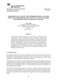
mentioned above exist (Figure 1). Volcanic gases participate in the chemistry of geothermal fluid and<br />
control the pH factor. Other components are dissolved from the surrounding rock. The physical<br />
parameters (temperature and pressure) are controlled by the heat source and flow of the fluid<br />
(permeability). Each geothermal reservoir has its own characteristics, but can resemble others in many<br />
ways. In the Pacific Arc, subduction volcanism is predominant; along the Atlantic Ridge, rifting<br />
volcanism is dominant. The reservoirs are built up of volcanic materials and in some cases overlaid by<br />
thick sediments (Wohletz and Heiken, 1992).<br />
The tectonic rifts control the main flow pattern of the geothermal fluid and must therefore be carefully<br />
mapped and understood. Most of the permeability is connected to fractured rock, in the range from<br />
microfractures to fissures and fractures as observed on the surface.<br />
3. MAIN TYPES OF <strong>GEOTHERMAL</strong> RESERVOIRS<br />
The combination of locally variable factors like enthalpy/temperature, chemical composition,<br />
permeability distribution, depth, etc., leads to a great variety of different geothermal reservoirs. The<br />
high-temperature reservoirs have been classified into several types based on the water temperature,<br />
pressure and phases. Water can be in a liquid or vapour phase or combined as two-phase fluid. The<br />
physical properties of water and steam are very well known and are found in steam tables.<br />
Calculations on the effect of lowering the pressure can then, be easily calculated as the fluid is in a<br />
state of saturation. The following is a brief description of the main types of reservoirs as they affect<br />
FIGURE 1 : A schematic model of a high-temperature geothermal system in Iceland<br />
(G.Ó. Fridleifsson, personal communication)
Report 9<br />
113<br />
Hossein-Pourazad<br />
geothermal well design and the production characteristics. There are several temperature criteria used<br />
in the classifications and there seems little agreement in the literature as to what the exact temperature<br />
ranges are. The World Bank classifies the geothermal resources based on temperature as: hightemperature<br />
(>150°C), medium-temperature (100-150°C), and low-temperature (
Hossein-Pourazad 114<br />
Report 9<br />
water level sinks below the<br />
well bottom. This transition<br />
to steam can be quite rapid<br />
and needs to be considered<br />
when designing wells,<br />
especially in fields where<br />
there has been a large drawdown.<br />
Vapour-dominated reservoirs<br />
are full of steam. The term<br />
“vapour-dominated” was first<br />
used by D. White in 1971.<br />
The main characteristics of<br />
this system are:<br />
(a) A discharge of steam<br />
only;<br />
(b) The discharge comes<br />
from a region where<br />
the pressure is nearly<br />
constant with depth.<br />
Depth (m)<br />
Temperature (°C)<br />
100 150 200 250 300 350<br />
0<br />
200<br />
400<br />
600<br />
800<br />
0<br />
200<br />
400<br />
600<br />
800<br />
1000<br />
1200<br />
1400<br />
1600<br />
1800<br />
2000<br />
Ne-22<br />
temperature<br />
boiling curve (T)<br />
pressure<br />
1000<br />
1200<br />
1400<br />
1600<br />
1800<br />
2000<br />
0 20 40 60 80 100 120<br />
Pressure (bar)<br />
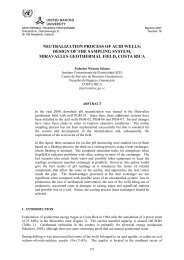
FIGURE 4: Typical temperature/pressure curves for the<br />
two-phase reservoir at Nesjavellir, SW-Iceland<br />
The steam discharge may initially be wet, saturated or super-heated. The pressure of the production<br />
zone is usually around 33 bars, equivalent to a saturation pressure for water and steam at 235°C.<br />
Table 1 lists basic technologies normally utilized, classified according to resource temperature.<br />
TABLE 1: Geothermal reservoir temperatures and common technologies<br />
Reservoir temperature Reservoir fluid Common use Technology commonly chosen<br />
Flash steam<br />
Combined (flash and binary) cycle<br />
High temperature -<br />
Power generation<br />
Water and/or steam Direct fluid use<br />
>220°C<br />
Direct use<br />
Heat exchangers<br />
Heat pumps<br />
Intermediate temperature -<br />
100-220°C<br />
Water<br />
Power generation<br />
Direct use<br />
Low temperature –<br />
50-150°C Water Direct use<br />
Binary cycle<br />
Direct fluid use<br />
Heat exchangers<br />
Heat pumps<br />
Direct fluid use<br />
Heat exchangers<br />
Heat pumps<br />
4. DESCRIPTION OF DRILLING TARGETS<br />
Siting of wells considers all the available geoscientific data from surface investigations and from<br />
existing wells. The goal is for the wells to intersect permeable fractures and formations in order to<br />
extract fluids of sufficient temperature. In most cases, the target is not as well defined as, for example,<br />
in oil drilling. This is not as big a problem as it may seem, as any fluid from the formation below a<br />
certain depth can enter the well and be exploited. At this time the depth of the well is decided, within
Report 9<br />
115<br />
Hossein-Pourazad<br />
a certain range, and also the depth of the production casing. Many wells are drilled vertically but now<br />
a good portion of them are drilled as directional wells. Directional drilling is adopted to increase the<br />
accuracy of drilling operations as well as to minimize environmental impacts. Drill pads for<br />
directional drilling can be located based on one or more of the reasons presented below:<br />
1. Topography;<br />
2. Upflow of the geothermal fluid controlled by tectonic lineaments;<br />
3. Distance from other manifestations;<br />
4. Environmental impacts.<br />
5. <strong>TEMPERATURE</strong> AND PRESSURE IN STATIC AND FLOWING <strong>WELL</strong>S<br />
Temperature is the most important parameter that must be considered when designing the casing<br />
programme for geothermal wells. There are three important casing design considerations concerning<br />
temperature:<br />
1. Maximum temperature along the wellbore affects other parameters such as steel type, strength,<br />
corrosion rate, scaling, pressures, thread lubricants, seal materials, cement design and cementing<br />
mechanics.<br />
2. The static geothermal temperature profile is defined as the earth temperature along the axis of<br />
the wellbore. This set of temperature versus depth data is extremely important for casing<br />
design, often being the initial data for many design calculations.<br />
3. The maximum change in temperature to which the casing string can be subjected. This<br />
temperature ranges between a higher temperature when the well is in a long-term flowing state<br />
and a lower temperature when it is shut-in in a long–term static condition. These temperature<br />
limits primarily affect the required steel strength and the design of the “set” stress as the casing<br />
is frozen in cement (Nicholson, 1984a).<br />
The static reservoir temperature and pressure are interpreted from the logged heating up data of the<br />
well. Once the well is flowing the dynamic conditions can be measured by lowering a logging tool<br />
down the hole against the flow. For the first exploration wells, the temperature conditions are not<br />
known and the “worst possible case” has to be considered in the design, i.e. when the temperature and<br />
pressure distribution follows the boiling point depth curve. Lacking such data, it is possible to<br />
calculate the expected flowing well temperature and pressure profiles by well simulators or<br />
spreadsheet modelling. During flow testing the mass flow and fluid enthalpy are also determined.<br />
6. <strong>WELL</strong> OUTPUT CURVES – MASS FLOW VS. <strong>WELL</strong>HEAD PRESSURE<br />
The well mass flow depends on reservoir permeability, temperature, the diameter of the well and<br />
wellhead pressure. If the permeability is low it will control how much flows into the well. At times<br />
the flow is almost constant, independent of wellhead pressure (see wells Krafla 13, Bjarnaflag 11 and<br />
Nesjavellir 9 in Figure 5). This occurs mainly in two-phase reservoirs with fluids of high enthalpy. In<br />
water-dominated reservoirs the rule is: the lower the wellhead pressure, the greater the mass flow.<br />
Here the inflow performance is also a factor, but when it is very good, the diameter of the well<br />
becomes the limiting factor. Experience has shown that for very permeable reservoirs the mass flow is<br />
proportional to the cross-sectional area of the casing. In mathematical terms, this can be expressed as:<br />
2<br />
Q<br />
2<br />
/ Q1<br />
= ( D2<br />
/ D1<br />
)<br />
(1)<br />
where Q = Mass flow (kg/s); and<br />
D = Diameter of the casing (").
Hossein-Pourazad 116<br />
Report 9<br />
This means that if you<br />
increase the diameter of the<br />
production casing from 9-<br />
5/8” to 13-3/8” you can<br />
expect the mass flow to be<br />
almost twice as large (see<br />
Figure 5 for wells Svartsengi<br />
4 with 9-5/8” casing vs.<br />
Svartsengi 8 and 11 with 13-<br />
3/8”). This relationship is<br />
important as it also allows<br />
you to “scale-up” the flow<br />
from a small diameter<br />
exploration hole to a larger<br />
size production hole (Finger<br />
et al., 1999).<br />
7. <strong>WELL</strong> <strong>DESIGN</strong><br />
The design procedure for a<br />
geothermal well is similar to<br />
that of oil wells. What is<br />
different is that temperature<br />
and pressure at depth must be<br />
considered as this influences<br />
the number of casing strings<br />
and the depths to which they<br />
must be run, to provide long<br />
term safety of the well and to<br />
allow control of blow-outs<br />
during drilling. Generally,<br />
well design will follow these steps:<br />
FIGURE 5: Mass flow vs. WHP for some high-temperature<br />
wells in Iceland (Thórhallsson and Ragnarsson, 1992)<br />
1. Determine the number of casing strings required and the diameter and lengths of each.<br />
The number of casing strings and depth are determined by the geological conditions, safety<br />
requirements and at times by official regulations. Usually there are three cemented casing strings in a<br />
high-temperature well: (a) surface casing, (b) anchor casing and (c) production casing. Additionally<br />
most wells have a slotted liner that is suspended from the production casing in the open section of the<br />
hole. During preparation of the wellsite, prior to the arrival of the drilling equipment a conductor<br />
casing is usually installed to 2-6 m.<br />
There are many factors that influence the selection of casing diameters. The main ones are well cost,<br />
rig availability and expected flow. Roughly the cost increases linearly with the diameter. The<br />
diameter of the production casing is usually decided first and then the other casing strings are selected<br />
based on the standard bit and casing sizes that give the desired clearances. Larger diameter holes are<br />
advantageous as it takes longer for scaling to restrict the flow and more repair operations can be<br />
carried out later in the life of the well. Interest has at times been shown in small diameter holes for<br />
exploration, as they are less expensive (Finger et al., 1999). The minimum diameter to which such<br />
wells can be restricted is ruled by which tools must be able to pass down the wellbore.
Report 9<br />
117<br />
Hossein-Pourazad<br />
Typical temperature-pressure-spinner logging tools will fit in to almost any reasonable size hole. But<br />
if more unusual tools, for example, imaging tools such as micro-scanner or a borehole televiewer are<br />
used, the heat-shielding which they sometimes require at high temperature, defines a minimum hole<br />
size.<br />
Core samples are sometimes used to validate a geological model of the reservoir or to assess the<br />
fracture dip, density and aperture. Diameter is not too important for this data, but sometimes a rock<br />
mechanics evaluation will need a minimum core diameter. Larger diameter cores also give better<br />
recovery in highly fractured or unconsolidated formation.<br />
The depth limit is sometimes determined by the hook load capacity of the drilling rig (tonnes), from<br />
the suspended weight of the drill string within the hole or by the weight of casing being lowered into<br />
the hole.<br />
2. Calculate the type and magnitude of loading: collapse, burst, and tension/compression.<br />
When the pressure difference, dP, is larger than 0 the inside pressure is greater than the outside<br />
pressure (burst). When it is less than 0 the outside pressure is greater (collapse):<br />
dP = P1 − P2<br />
(2)<br />
where P1<br />
P2<br />
= Casing inside pressure (bar);<br />
= Outside pressure (bar).<br />
The greatest collapse pressure occurs during cementing of the casing. The pressure, P (bar), as a<br />
function of depth is the hydrostatic pressure calculated as:<br />
where h = Depth (m);<br />
ρ = Water or cement density (kg/m 3 );<br />
g = Gravity constant.<br />
P = hρg /100,000<br />
(3)<br />
The cement density assumed for the high-temperature cement with silica flour and perlite is 1700<br />
kg/m 3 . Collapse pressure is exerted by the cement slurry during the cementing operation, when the<br />
inner-string method is used. The static pressures and calculated collapse vs. depth for three sizes of<br />
casing are shown in Table 2. These factors usually dictate the casing wall thickness (lb/ft). The<br />
casing strength numbers used in the Table are from the IFP Drilling Manual (Gabolde and Nguyen,<br />
1999).<br />
The burst pressure is the maximum inside pressure that can be expected at the wellhead whether the<br />
well is hot or cold. For hot water reservoirs, the maximum pressure is the maximum WHP during<br />
discharge. For vapour-dominated reservoirs, the maximum pressure is the steam zone pressure while<br />
the well is closed. The expected maximum pressure can be determined in several ways: (a) historic<br />
data from flowing wells, (b) assume the temperature and pressure distribution in the reservoir (the<br />
“worst possible case” is the BPD curve) and run wellbore simulators (c) for vapour-dominated wells,<br />
assume a steam-filled well from the bottom. Gases can accumulate in the production casing and<br />
depress the water level to the casing shoe, and sometimes the water level is depressed by compressed<br />
air to simulate wells to discharge.<br />
3. Match casing strength of API casing with the requirements in step (2) after applying the<br />
appropriate safety factors.
Hossein-Pourazad 118<br />
Report 9<br />
TABLE 2: The static pressures and the required collapse resistance vs. depth; wall thickness weight (W)<br />
per unit length (L) is then selected that exceeds the collapse for three sizes of casings<br />
(Gabolde and Nguyen, 1999)<br />
Depth<br />
(m)<br />
Minimum collapse resistance Casing 9 5/8" Casing 13 3/8" Casing 18 5/8"<br />
dP<br />
Pw Pc dP<br />
Wall<br />
Wall<br />
Wall<br />
collapse W/L<br />
W/L<br />
W/L<br />
water cement static<br />
thickness thickness thickness<br />
w.saf. fac. (lb/ft) (lb/ft) (lb/ft)<br />
(bar) (bar) (bar)<br />
(mm)<br />
(mm)<br />
(mm)<br />
(bar)<br />
0 1 1 0 30<br />
100 10.81 17.68 6.87 38.24<br />
200 20.62 34.35 13.73 46.48<br />
300 30.43 51.03 20.60 54.72<br />
400 40.24 67.71 27.47 62.96<br />
500 50.05 84.39 34.34 71.20<br />
600 59.86 101.06 41.20 79.44<br />
700 69.67 117.74 48.07 87.68<br />
800 79.48 134.42 54.94 95.92<br />
900 89.29 151.09 61.80 104.16<br />
1000 99.10 167.77 68.67 112.40<br />
36 8.9<br />
NB: All casings are K-55.<br />
54.5 9.7<br />
61 10.9<br />
68 12.2<br />
87.5 11<br />
8. DIRECTIONAL DRILLING<br />
There are a number of reasons for directional drilling: it may be necessary to correct an inadvertent<br />
change in hole direction, surface geographical features or boundaries may prevent the rig from being<br />
above the target, or reservoir evaluation criteria may require that the hole intercept as many high angle<br />
fractures as possible. If either of the latter two situations exist, the direction of the hole can be<br />
controlled by causing the hole to deviate from vertical at some depth.<br />
If conventional directional drilling is planned, the principal decisions are choice of kick-off point,<br />
determination of angle-building rate and final inclination. The kick-off point is affected by many<br />
variables including formation, casing points and temperature, but it is usually fairly high in the hole<br />
for geothermal drilling, because the down-hole motors and steering tools are limited by the<br />
temperatures they can withstand (Finger et al., 1999). Now good hole cooling and procedures allow<br />
these tools to be used to total depth.<br />
9. CASING <strong>DESIGN</strong><br />
The casing for a geothermal project normally represents 20-30% of the well cost. Thus, casing is a<br />
major initial well cost (Nicholson, 1984b).<br />
Any failure of the casing string leads to loss of the well, or at least a great amount of financial load in<br />
order to re-establish the well for safe production. Therefore, the design of the casing strings is a<br />
critical part of the economics of a geothermal project (Nicholson, 1984b).<br />
Casing string is mainly designed considering the temperature and pressure exerted from formation<br />
and/or from hydrothermal fluid within the well. In this paper casing designing is based on both<br />
temperature and different pressures. Regulatory requirements in the drilling permit will determine
Report 9<br />
119<br />
Hossein-Pourazad<br />
other aspects of the casing design and blow-out prevention equipment (BOPE). A typical<br />
specification is that surface casing is at least 10% of the total depth and that one-third of the hole be<br />
behind casing at any given time. Once the minimum required depth (presented later in detail) is<br />
reached, casing will normally be run unless the formation is particularly fractured and broken. It is<br />
important to have competent rock at the casing shoe, as it is normally required to do a pressure test by<br />
drilling out the shoe into a new formation, then applying a pressure gradient above hydrostatic<br />
pressure to the wellbore. This procedure evaluates the well’s ability to withstand high pressures<br />
without breaking down the formation or the cement around the casing and is the basis for establishing<br />
the temperature to which the well can be drilled without setting another casing string. Clearly, if there<br />
is not competent rock around the shoe, the wellbore will not be able to withstand a high pressure<br />
gradient and the ability to advance the well to the desired depth/temperature will be compromised. If<br />
the minimum casing depth is reached and there is no competent rock, it is often desirable or necessary<br />
to continue drilling until a better formation is found (Finger et al., 1999).<br />
Experience from drilling in high-temperature geothermal areas in Iceland indicates that temperatures<br />
and pressures to be expected on the well bottom may be assumed to follow the boiling curve based on<br />
the assumption of the water being at boiling conditions at any depth. This means that bottom<br />
temperature and pressure in a well of 2000 m depth may be as high as 340°C and 145 bar,<br />
respectively. At these conditions it may be difficult to design a string of casing based on the<br />
conventional requirements of keeping the casing material within the elastic limits (Karlsson, 1978).<br />
Well casing used in Icelandic geothermal wells has been manufactured in accordance with API<br />
specifications. These specifications provide no minimum strength requirements at elevated<br />
temperatures, but tensile properties in cold conditions for various API grades of casing are presented<br />
in Table 3.<br />
TABLE 3: Tensile requirements of casing pipe manufactured<br />
in accordance with API specification 5A<br />
Casing<br />
grade<br />
Min.<br />
yield<br />
(kg/mm 2 )<br />
Max.<br />
strength<br />
(kg/mm 2 )<br />
Min. tensile<br />
stength<br />
(kg/mm 2 )<br />
Min.<br />
elongation<br />
(% in 2”)<br />
H-40 28.1 - 42.2 29.5<br />
J-55 38.7 56.2 52.7 24.0<br />
K-55 38.7 56.2 66.8 19.5<br />
N-80 56.2 77.3 70.3 18.5<br />
C-75 52.7 63.3 66.8 19.5<br />
Loads on casing in a well may be of various types and occur during the running of the casing,<br />
cementing, drilling and after completion of the well. These loads may occur both in the axial direction<br />
of the casing or in the redial direction, inwards or outwards.<br />
Of the various possible load combinations acting on the casing string, the most critical seem to be<br />
caused by pressure and thermal expansion (Karlsson, 1978). Collapse and burst pressures are<br />
explained in detail in the following sections.<br />
9.1 Collapse<br />
Collapse pressure is usually found from the cement slurry column during cementing operations. There<br />
are several formulas for various ranges of D/t (diameter/thickness ratio) to calculate collapse pressure.<br />
For example, (according to Table 4), for a 18⅝” casing, D/t is 43. Then from Table 5 it is found that
Hossein-Pourazad 120<br />
Report 9<br />
quality K-55 can be selected to set at the mentioned depth in Table 2. The formula below is used for<br />
calculating the elastic collapse pressure (API, 1989):<br />
TABLE 4: D/t for three sizes of casings<br />
Diameter<br />
(")<br />
Diameter<br />
(mm)<br />
Thickness<br />
(mm)<br />
Diameter/thickness<br />
ratio<br />
9 5/8 244.5 8.9 27.47<br />
13 3/8 339.7 12.2 27.84<br />
18 5/8 473 11 43<br />
TABLE 5: Diameter/thickness ratio range for elastic collapse<br />
Grade<br />
D/t range<br />
H-40 42.64 and greater<br />
H-50 38.83 and greater<br />
J-K-55 37.21 and greater<br />
J-60 35.73 and greater<br />
( D / t)( ( D / t)<br />
−1) 2<br />
6<br />
46.95×<br />
10<br />
P E =<br />
(4)<br />
where P E = Minimum collapse pressure for the elastic range of collapse (psi);<br />
D = Diameter of casing (");<br />
t = Wall thickness of casing (").<br />
For other ranges of D/t, the calculation can be done in the same way using a different formula.<br />
9.2 Burst<br />
Burst pressure is an internal pressure from fluids within the casing. Maximum burst pressure is<br />
usually when a well is shut and full of gas, or under compressed air, commonly used to stimulate the<br />
well to start flowing. The burst resistance to casings is defined by the equation (API and ISO<br />
standards; Rath, 2005):<br />
P = 2ts<br />
/(( D − 2t)<br />
× SF)<br />
(5)<br />
where P = Internal pressure (N/mm 2 );<br />
t = Thickness of pipe wall (mm);<br />
s = Yield strength (N/mm 2 );<br />
D = Outside diameter of pipe (mm);<br />
SF = Safety factor (generally 1.5-10.1 for bursting pressure).<br />
9.3 Determination of minimum casing depth<br />
The depth of the production casing is determined by how deep fluids from the colder formations need<br />
to be isolated from entering the hole and at times by the geology. One of the main determinants,<br />
however, has to do with minimum depth for safety reasons. Government regulations sometimes
Report 9<br />
121<br />
Hossein-Pourazad<br />
stipulate how deep the casings need to be run, usually to insure that the near-surface aquifers are not<br />
contaminated by cross contamination. Safety aspects are also considered. From the technical side<br />
there are four main criteria that have been applied to determine the minimum casing depth:<br />
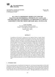
1. In the New Zealand<br />
Recommended Code of<br />
Practice the criteria is<br />
that the pressure from<br />
overburden (soil) at the<br />
last casing shoe, shall<br />
exceed the pressure<br />
from a steam filled<br />
well. Thus once the<br />
final depth of the well<br />
has been decided, the<br />
hydrostatic pressure<br />
for the BPD curve is<br />
drawn to that depth.<br />
The minimum depth of<br />
casing according to the<br />
NZ method is then<br />
found by extending the<br />
bottom hole pressure<br />
up the well, minus the<br />
steam density, until it<br />
intersects the overburden<br />
pressure. This<br />
is then the minimum<br />
casing depth of the<br />
production casing. By<br />
repeating the same<br />
method the minimum<br />
depth of the anchor<br />
casing and then surface<br />
casing is determined<br />
(Figure 6). This<br />
method will assure that<br />
a blow-out outside the<br />
casing will not occur.<br />
2. A method used in<br />
Iceland assumes the<br />
BPD for new fields.<br />
From well simulation<br />
studies the pressure<br />
profile for a flowing<br />
well is determined,<br />
assuming inflow at<br />
bottom. The liquid<br />
will immediately be<br />
transformed into twophase<br />
flow up the well.<br />
The minimum depth is<br />
Depth (m)<br />
Depth (m)<br />
Pressure (bar)<br />
0 100 200 300 400 500 600<br />
0 200 m<br />
200<br />
400<br />
600<br />
800<br />
1000<br />
1200<br />
1400<br />
1600<br />
1800<br />
2000<br />
2200<br />
2400<br />
2600<br />
2800<br />
700 m<br />
●TD =2500 m.<br />
over burden<br />
BPDC<br />
steam curve 2<br />
steam curve 1<br />
●over burden density =2.2 gr/cm3 ●Minimum casing depth (MCD) =200, 700 m.<br />
FIGURE 6: The New Zealandic method to<br />
determine the minimum casing depth for<br />
high-temperature geothermal wells<br />
0 50 100 150 200 250 300 350<br />
0<br />
500<br />
1000<br />
1500<br />
2000<br />
2500<br />
3000<br />
200 m<br />
750 m<br />
Pressure (bar)<br />
Mud<br />
Sabalan<br />
2500<br />
BPDC<br />
FIGURE 7: The Icelandic method to determine the minimum<br />
depth of casing using mud as blow-out preventer<br />
750
Hossein-Pourazad 122<br />
Report 9<br />
Depth (m)<br />
500<br />
1000<br />
1500<br />
2000<br />
2500<br />
3000<br />
0 50 100 150 200 250 300<br />
0<br />
105 m<br />
440 m<br />
1050 m<br />
Pressure (bar)<br />
Pure w ater<br />
BPDC<br />
Sabalan<br />
FIGURE 8: The Icelandic method to determine the minimum depth<br />
of casing using pure water as blow-out preventer<br />
then determined by<br />
how long a column of<br />
heavy mud of 1.4<br />
gr/cm 3 density is<br />
required to balance this<br />
pressure (Figure 7).<br />
3. The other method used<br />
in Iceland is to<br />
consider the actual<br />
case, or most likely<br />
case, for the<br />
temperature and<br />
pressure down-hole.<br />
Then typically, the<br />
fluid only turns to twophase<br />
flow about half<br />
way up the hole. This<br />
pressure profile is then<br />
balanced by pure water<br />
only. Pumping only<br />
water into the well<br />
insures that the drill<br />
string can be retrieved, even if there is an underground blow-out in the well (Figure 8).<br />
2500<br />
1050<br />
440<br />
It is interesting to note that the results obtained by applying these four methods lead to rather similar<br />
results for the minimum casing depth. Method 4 makes the production casing perhaps 100-200 m<br />
longer than the others. These methods mean that to reach modern day depths of high-temperature<br />
drilling, three drill strings have to be landed and cemented (surface-anchor-production). This is the<br />
general practice around the world. Conductor casings are installed when the drill site is being<br />
prepared, so the total number of casing strings is usually four.<br />
10. CONCLUSIONS<br />
• High-temperature geothermal wells are mostly connected to volcanic areas in rift and subduction<br />
zones. The “worst possible case” to be used as the basis for designing a high-temperature<br />
geothermal well is the boiling point depth curve.<br />
• A well simulation model can be a powerful tool in predicting the temperature and pressure along<br />
the well axis. When actual measurements are available from existing wells the casing<br />
programme can be adapted to reservoir conditions.<br />
• Temperature and pressure for a well, flowing or shut-in, are the most important parameters for<br />
the mechanical design of the casing.<br />
• Collapse pressure due to cement density is often what defines casing thickness.<br />
• Three methods to determine the number of casing strings and minimum depths are presented.
Report 9<br />
123<br />
REFERENCES<br />
Hossein-Pourazad<br />
API, 1989: API Bulletin on formulas and calculations for casing, tubing, drill pipe and line pipe<br />
properties. American Petroleum Institute, Washington DC, API Bulletin 5C3-89, 40 pp.<br />
Finger, J., Jacobson, R., Hickox, C., Combs, J., Polk, G., and Goranson, C., 1999: Procedures and<br />
recommendations for slimhole drilling and testing in geothermal exploration. Sandia National<br />
Laboratories, Albuquerque, NM, Sandia report SAND99-1976.<br />
Gabolde G., and Nguyen, J.P., 1999: Drilling data handbook. Gulf Publishing Co., Houston, TX, 542<br />
pp.<br />
Karlsson, Th., 1978: Casing design for high temperature geothermal wells. Geoth. Resource Council,<br />
Transactions, 2, 355-358.<br />
Nicholson, R.W., 1984a: Casing design for temperature regimes in geothermal wells. Geoth. Resourc.<br />
Council Bulletin, 1984-May, 23-26.<br />
Nicholson, R.W., 1984b: Geothermal casing design. Geoth. Resourc. Council, Bulletin, 1984-May,<br />
18-23.<br />
Rath, 2005: Bursting or working tubing or pipe pressures, Barlow’s formula. Rath Manufacturing<br />
Co., Inc., website: www.rathmfg.com/barlow.htm.<br />
Rybach, L., and Muffler, L.J.P. (eds.), 1981: Geothermal systems, principles and case histories. John<br />
Wiley & Sons, Ltd., Chichester, 359 pp.<br />
Thórhallsson, S., and Ragnarsson, Á., 1992: What is geothermal steam worth Proceedings of the<br />
International Conference on Industrial Uses of Geothermal Energy, Reykjavik, 1992, PS-III, 15 pp.<br />
Wohletz, K., and Heiken, G., 1992: Volcanology and geothermal energy. University of California<br />
Press, Berkeley, Ca., 432 pp.