CPVC Near Boiler Venting Kit - Triangle Tube
CPVC Near Boiler Venting Kit - Triangle Tube
CPVC Near Boiler Venting Kit - Triangle Tube

You also want an ePaper? Increase the reach of your titles
YUMPU automatically turns print PDFs into web optimized ePapers that Google loves.
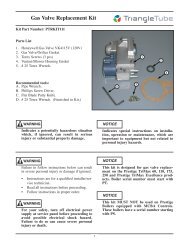
<strong>CPVC</strong> <strong>Near</strong> <strong>Boiler</strong> <strong>Venting</strong> <strong>Kit</strong><br />
<strong>Kit</strong> Part Number:<br />
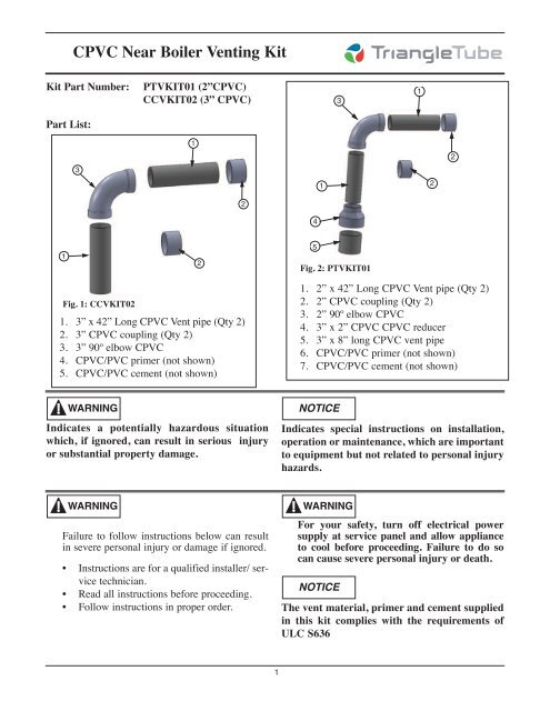
PTVKIT01 (2”<strong>CPVC</strong>)<br />
CCVKIT02 (3” <strong>CPVC</strong>)<br />
3<br />
1<br />
Part List:<br />
1<br />
2<br />
3<br />
1<br />
2<br />
2<br />
4<br />
1<br />
2<br />
5<br />
Fig. 2: PTVKIT01<br />
Fig. 1: CCVKIT02<br />
1. 3” x 42” Long <strong>CPVC</strong> Vent pipe (Qty 2)<br />
2. 3” <strong>CPVC</strong> coupling (Qty 2)<br />
3. 3” 90º elbow <strong>CPVC</strong><br />
4. <strong>CPVC</strong>/PVC primer (not shown)<br />
5. <strong>CPVC</strong>/PVC cement (not shown)<br />
1. 2” x 42” Long <strong>CPVC</strong> Vent pipe (Qty 2)<br />
2. 2” <strong>CPVC</strong> coupling (Qty 2)<br />
3. 2” 90º elbow <strong>CPVC</strong><br />
4. 3” x 2” <strong>CPVC</strong> <strong>CPVC</strong> reducer<br />
5. 3” x 8” long <strong>CPVC</strong> vent pipe<br />
6. <strong>CPVC</strong>/PVC primer (not shown)<br />
7. <strong>CPVC</strong>/PVC cement (not shown)<br />
WARNING<br />
Indicates a potentially hazardous situation<br />
which, if ignored, can result in serious injury<br />
or substantial property damage.<br />
NOTICE<br />
Indicates special instructions on installation,<br />
operation or maintenance, which are important<br />
to equipment but not related to personal injury<br />
hazards.<br />
WARNING<br />
Failure to follow instructions below can result<br />
in severe personal injury or damage if ignored.<br />
• Instructions are for a qualified installer/ service<br />
technician.<br />
• Read all instructions before proceeding.<br />
• Follow instructions in proper order.<br />
WARNING<br />
For your safety, turn off electrical power<br />
supply at service panel and allow appliance<br />
to cool before proceeding. Failure to do so<br />
can cause severe personal injury or death.<br />
NOTICE<br />
The vent material, primer and cement supplied<br />
in this kit complies with the requirements of<br />
ULC S636<br />
1
<strong>CPVC</strong> <strong>Near</strong> <strong>Boiler</strong> <strong>Venting</strong> <strong>Kit</strong><br />
Installation - CCVKIT02<br />
WARNING<br />
This kit is designed to be installed on the<br />
Challenger CC 150s and should be installed per<br />
the instructions found in the Challenger PVC,<br />
<strong>CPVC</strong> & SS Vent Supplements.<br />
NOTICE<br />
The purpose of the kit is to provide the installer<br />
with <strong>CPVC</strong> venting materials for use on<br />
Challenger CC 150s <strong>Boiler</strong> that requires the first<br />
seven equivalent feet of venting to be <strong>CPVC</strong>.<br />
1. If using the elbow included in the kit, measure<br />
straight pipe(s) and cut to desired length(s) as<br />
necessary.<br />
NOTICE<br />
The elbow supplied in the kit has an equivalent<br />
of 5 feet. A minimum length of pipe of 2 feet<br />
must be used in conjunction with the elbow.<br />
2. If not using the elbow included in the kit <strong>CPVC</strong><br />
both pipes must be used without any cuts. Full<br />
lengths are required.<br />
3. If a transition to PVC is made, ensure that the<br />
supplied <strong>CPVC</strong>/PVC primer and cement are<br />
used on the transition.<br />
NOTICE<br />
The purpose of this kit is to provide the installer<br />
with <strong>CPVC</strong> venting materials for use in the transition<br />
of a 3 inch vent system to a 2 inch vent system<br />
where the first seven equivalent of venting must be<br />
<strong>CPVC</strong> material.<br />
1. The assembly of <strong>CPVC</strong> transition vent system<br />
begins with the insertion of the 8 inch long<br />
<strong>CPVC</strong> pipe into the vent outlet adapter of the<br />
boiler.<br />
2. The 3” x 2” reducer fitting must be assembled<br />
to the 3 inch x 8 inch long <strong>CPVC</strong> pipe.<br />
NOTICE<br />
The elbow supplied in the kit has an equivalent<br />
length of 5 feet. A minimum length of <strong>CPVC</strong> pipe<br />
of 2 feet must be used in conjunction with the<br />
elbow.<br />
4. If not using the elbow included in the kit both<br />
<strong>CPVC</strong> pipes must be used without any cuts.<br />
Both full lengths are required.<br />
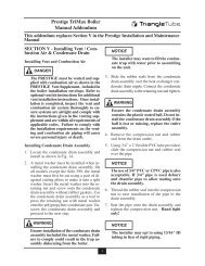
2 Inch Vent Pipe<br />
<strong>CPVC</strong> Material<br />
Instructions PTRKIT01 (2”)<br />
Installation Guidelines<br />
WARNING<br />
This kit is designed to be installed on the Prestige<br />
PS 60, PS 110 and PE 110 only. This kit should be<br />
installed per the instructions found in the Prestige<br />
PVC, <strong>CPVC</strong>, PP & SS Vent supplement.<br />
2 Inch Vent Pipe<br />
<strong>CPVC</strong> Material<br />
3 x 2 Bell Reducer<br />
<strong>CPVC</strong> Material<br />
3 x 8 inch long Vent<br />
Pipe <strong>CPVC</strong> Material<br />
Fig. 3: PTVKIT01 - Vertical <strong>Venting</strong><br />
2
<strong>CPVC</strong> <strong>Near</strong> <strong>Boiler</strong> <strong>Venting</strong> <strong>Kit</strong><br />
5. If a transition to PVC is made, ensure that the<br />
supplied <strong>CPVC</strong>/PVC primer and cement are<br />
used on the transition.<br />
Installation Guidelines<br />
WARNING<br />
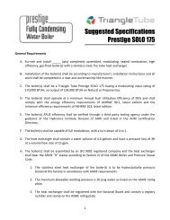
2 Inch Vent Pipe<br />
PVC or <strong>CPVC</strong><br />
Material<br />
2 Inch 90º Elbow<br />
<strong>CPVC</strong> Material<br />
2 Inch Vent Pipe<br />
<strong>CPVC</strong> Material<br />
3 x 2 Bell Reducer<br />
<strong>CPVC</strong> Material<br />
3 x 8 inch Long Vent<br />
Pipe <strong>CPVC</strong> Material<br />
Fig. 4: PTVKIT01 - Horizontal <strong>Venting</strong><br />
Prior to assembly and installation of the vent<br />
system, the installer must reference the appropriate<br />
vent supplement provided with the boiler.<br />
Failure to comply with the requirements/guidelines<br />
of the vent supplement can result in the failure<br />
of the vent system.<br />
1. The installer should install the vent / combustion<br />
air piping working from the boiler to the<br />
piping termination. The piping should not<br />
exceed the lengths given in vent supplement<br />
provide with the boiler for either the vent or<br />
combustion air.<br />
3<br />
2. The installer should cut the pipe to the required<br />
length and deburr the inside and outside of both<br />
ends.<br />
3. The installer should chamfer the outside of the<br />
pipe ends to allow even distribution of cement<br />
when joining.<br />
4. The installer should dry assemble the vent system<br />
prior to assembling any joints to ensure<br />
proper fit.<br />
5. The pipe ends and fittings should be cleaned<br />
and dried thoroughly prior to assembly of the<br />
joint.<br />
6. When assembling a joint the installer should:<br />
a. Handle fittings and pipes carefully to prevent<br />
contamination of surfaces<br />
b. Apply a liberal amount of primer to both<br />
surfaces - the end of the pipe and the insert<br />
socket of the fitting.<br />
c. Apply a light uniform coating of approved<br />
cement to both surfaces - the end of the pipe<br />
and the insert socket of the fitting, while the<br />
primer is still wet.<br />
d. A second coat of approved cement should<br />
be applied to the mating surfaces. The<br />
installer should avoid, however, using too<br />
much cement on the socket of the fitting to<br />
prevent a buildup of cement on the inside.<br />
e. With the cement still wet, the pipe end<br />
should be inserted into the socket of the fitting<br />
and twisted 1/4 of a full turn. Ensure<br />
the pipe end is inserted fully into the socket<br />
of the fitting.<br />
f. Any excess cement should be wiped clean<br />
from the joint. Inspect the joint to ensure a<br />
smooth bead of cement is noticed around<br />
the entire joint seam.
<strong>CPVC</strong> <strong>Near</strong> <strong>Boiler</strong> <strong>Venting</strong> <strong>Kit</strong><br />
7. The installer should use perforated metal strap<br />
hangers or equivalent pipe hangers suitable for<br />
plastic pipe to support the piping. The hangers<br />
must be spaced at a maximum of every 5 feet<br />
[1.5 m] of horizontal and vertical run of piping.<br />
A support must be placed near the boiler and<br />
every change in direction vertical or horizontal<br />
(i.e elbow). Do not penetrate any part of the piping<br />
or vent system with fastener.<br />
NOTICE<br />
Pipe hangers should not be tightly clamped to<br />
pipe to allow for thermal expansion/contraction<br />
movement. Pipe clamps or hangers should not<br />
contain any sharp edges which can damage the<br />
pipe<br />
8. The vent should be sloped continuously from<br />
the termination back to the boiler with at least<br />
1/4” drop per foot [6 mm/30 cm] of run. Do not<br />
allow any sags in the run of piping.<br />
WARNING<br />
Do not pitch the vent downward away from the<br />
boiler. Potential condensate damage to the<br />
building exterior or to the surrounding landscape<br />
and/or potential risks of icing and blockage<br />
of the vent piping could occur.<br />
9. Maintain a minimum clearance of 1/4” [6 mm]<br />
between the vent pipe and all materials, combustible<br />
or non-combustible for 3” and 4”<br />
PVC/<strong>CPVC</strong> vents or 1” [2.5 cm] for 2”<br />
PVC/<strong>CPVC</strong> vents. The installer must seal any<br />
wall, floor or ceiling penetrations as per local<br />
code requirements.<br />
NOTICE<br />
Do not insulate any vent pipes runs that pass<br />
through unconditioned areas.<br />
Date: 3/14/12<br />
4<br />
2012-5 <strong>CPVC</strong> <strong>Venting</strong> Initiation <strong>Kit</strong>